EP2646310B1 - Diagonalstrebenvorrichtung, verfahren zu ihrer herstellung und mittels diagonalstrebenvorrichtung verstärkter kraftfahrzeugunterboden - Google Patents
Diagonalstrebenvorrichtung, verfahren zu ihrer herstellung und mittels diagonalstrebenvorrichtung verstärkter kraftfahrzeugunterboden Download PDFInfo
- Publication number
- EP2646310B1 EP2646310B1 EP11773999.5A EP11773999A EP2646310B1 EP 2646310 B1 EP2646310 B1 EP 2646310B1 EP 11773999 A EP11773999 A EP 11773999A EP 2646310 B1 EP2646310 B1 EP 2646310B1
- Authority
- EP
- European Patent Office
- Prior art keywords
- struts
- diagonal strut
- joint element
- strut device
- diagonal
- Prior art date
- Legal status (The legal status is an assumption and is not a legal conclusion. Google has not performed a legal analysis and makes no representation as to the accuracy of the status listed.)
- Not-in-force
Links
- 238000000034 method Methods 0.000 title claims description 7
- 238000004519 manufacturing process Methods 0.000 title claims description 5
- 239000007769 metal material Substances 0.000 claims description 16
- 229920002430 Fibre-reinforced plastic Polymers 0.000 claims description 14
- 239000011248 coating agent Substances 0.000 claims description 14
- 238000000576 coating method Methods 0.000 claims description 14
- 239000011151 fibre-reinforced plastic Substances 0.000 claims description 14
- 239000000463 material Substances 0.000 claims description 13
- 238000004512 die casting Methods 0.000 claims description 12
- 229910052751 metal Inorganic materials 0.000 claims description 11
- 239000002184 metal Substances 0.000 claims description 10
- 239000002131 composite material Substances 0.000 claims description 8
- 239000000835 fiber Substances 0.000 claims description 4
- 230000015572 biosynthetic process Effects 0.000 claims description 3
- 238000001816 cooling Methods 0.000 claims description 3
- 229910001092 metal group alloy Inorganic materials 0.000 claims description 3
- 238000007599 discharging Methods 0.000 claims 1
- 230000003014 reinforcing effect Effects 0.000 claims 1
- 238000005304 joining Methods 0.000 description 9
- 238000005266 casting Methods 0.000 description 7
- 239000010410 layer Substances 0.000 description 6
- XAGFODPZIPBFFR-UHFFFAOYSA-N aluminium Chemical compound [Al] XAGFODPZIPBFFR-UHFFFAOYSA-N 0.000 description 3
- 238000005058 metal casting Methods 0.000 description 3
- 229920000049 Carbon (fiber) Polymers 0.000 description 2
- FYYHWMGAXLPEAU-UHFFFAOYSA-N Magnesium Chemical compound [Mg] FYYHWMGAXLPEAU-UHFFFAOYSA-N 0.000 description 2
- 239000000853 adhesive Substances 0.000 description 2
- 230000001070 adhesive effect Effects 0.000 description 2
- 239000012790 adhesive layer Substances 0.000 description 2
- 229910045601 alloy Inorganic materials 0.000 description 2
- 239000000956 alloy Substances 0.000 description 2
- 229910052782 aluminium Inorganic materials 0.000 description 2
- 239000004917 carbon fiber Substances 0.000 description 2
- 238000010276 construction Methods 0.000 description 2
- 239000007788 liquid Substances 0.000 description 2
- 229910052749 magnesium Inorganic materials 0.000 description 2
- 239000011777 magnesium Substances 0.000 description 2
- VNWKTOKETHGBQD-UHFFFAOYSA-N methane Chemical compound C VNWKTOKETHGBQD-UHFFFAOYSA-N 0.000 description 2
- 239000004033 plastic Substances 0.000 description 2
- 229920003023 plastic Polymers 0.000 description 2
- 238000003466 welding Methods 0.000 description 2
- 229910000838 Al alloy Inorganic materials 0.000 description 1
- CWYNVVGOOAEACU-UHFFFAOYSA-N Fe2+ Chemical compound [Fe+2] CWYNVVGOOAEACU-UHFFFAOYSA-N 0.000 description 1
- WHXSMMKQMYFTQS-UHFFFAOYSA-N Lithium Chemical compound [Li] WHXSMMKQMYFTQS-UHFFFAOYSA-N 0.000 description 1
- 229910000861 Mg alloy Inorganic materials 0.000 description 1
- 229910000831 Steel Inorganic materials 0.000 description 1
- RTAQQCXQSZGOHL-UHFFFAOYSA-N Titanium Chemical compound [Ti] RTAQQCXQSZGOHL-UHFFFAOYSA-N 0.000 description 1
- 238000004026 adhesive bonding Methods 0.000 description 1
- 230000002411 adverse Effects 0.000 description 1
- 229910052790 beryllium Inorganic materials 0.000 description 1
- ATBAMAFKBVZNFJ-UHFFFAOYSA-N beryllium atom Chemical compound [Be] ATBAMAFKBVZNFJ-UHFFFAOYSA-N 0.000 description 1
- 239000000919 ceramic Substances 0.000 description 1
- 230000007797 corrosion Effects 0.000 description 1
- 238000005260 corrosion Methods 0.000 description 1
- 230000006378 damage Effects 0.000 description 1
- 238000011161 development Methods 0.000 description 1
- 230000018109 developmental process Effects 0.000 description 1
- 238000007598 dipping method Methods 0.000 description 1
- 230000000694 effects Effects 0.000 description 1
- 229920006332 epoxy adhesive Polymers 0.000 description 1
- 238000003780 insertion Methods 0.000 description 1
- 230000037431 insertion Effects 0.000 description 1
- 229910052744 lithium Inorganic materials 0.000 description 1
- 238000003754 machining Methods 0.000 description 1
- 239000000155 melt Substances 0.000 description 1
- 238000002844 melting Methods 0.000 description 1
- 230000008018 melting Effects 0.000 description 1
- 150000002739 metals Chemical class 0.000 description 1
- 238000007750 plasma spraying Methods 0.000 description 1
- 239000000843 powder Substances 0.000 description 1
- 229910052710 silicon Inorganic materials 0.000 description 1
- 239000010703 silicon Substances 0.000 description 1
- 238000007711 solidification Methods 0.000 description 1
- 230000008023 solidification Effects 0.000 description 1
- 238000004528 spin coating Methods 0.000 description 1
- 238000005507 spraying Methods 0.000 description 1
- 239000010959 steel Substances 0.000 description 1
- 230000003685 thermal hair damage Effects 0.000 description 1
- 239000010936 titanium Substances 0.000 description 1
- 229910052719 titanium Inorganic materials 0.000 description 1
- 238000004804 winding Methods 0.000 description 1
Images
Classifications
-
- B—PERFORMING OPERATIONS; TRANSPORTING
- B62—LAND VEHICLES FOR TRAVELLING OTHERWISE THAN ON RAILS
- B62D—MOTOR VEHICLES; TRAILERS
- B62D21/00—Understructures, i.e. chassis frame on which a vehicle body may be mounted
- B62D21/06—Understructures, i.e. chassis frame on which a vehicle body may be mounted of X-shaped or fork-shaped construction, i.e. having members which form an X or fork as the frame is seen in plan view
-
- B—PERFORMING OPERATIONS; TRANSPORTING
- B22—CASTING; POWDER METALLURGY
- B22D—CASTING OF METALS; CASTING OF OTHER SUBSTANCES BY THE SAME PROCESSES OR DEVICES
- B22D17/00—Pressure die casting or injection die casting, i.e. casting in which the metal is forced into a mould under high pressure
-
- B—PERFORMING OPERATIONS; TRANSPORTING
- B22—CASTING; POWDER METALLURGY
- B22D—CASTING OF METALS; CASTING OF OTHER SUBSTANCES BY THE SAME PROCESSES OR DEVICES
- B22D19/00—Casting in, on, or around objects which form part of the product
- B22D19/04—Casting in, on, or around objects which form part of the product for joining parts
-
- B—PERFORMING OPERATIONS; TRANSPORTING
- B62—LAND VEHICLES FOR TRAVELLING OTHERWISE THAN ON RAILS
- B62D—MOTOR VEHICLES; TRAILERS
- B62D25/00—Superstructure or monocoque structure sub-units; Parts or details thereof not otherwise provided for
- B62D25/08—Front or rear portions
- B62D25/087—Luggage compartments
-
- B—PERFORMING OPERATIONS; TRANSPORTING
- B62—LAND VEHICLES FOR TRAVELLING OTHERWISE THAN ON RAILS
- B62D—MOTOR VEHICLES; TRAILERS
- B62D25/00—Superstructure or monocoque structure sub-units; Parts or details thereof not otherwise provided for
- B62D25/20—Floors or bottom sub-units
-
- B—PERFORMING OPERATIONS; TRANSPORTING
- B62—LAND VEHICLES FOR TRAVELLING OTHERWISE THAN ON RAILS
- B62D—MOTOR VEHICLES; TRAILERS
- B62D29/00—Superstructures, understructures, or sub-units thereof, characterised by the material thereof
- B62D29/001—Superstructures, understructures, or sub-units thereof, characterised by the material thereof characterised by combining metal and synthetic material
-
- B—PERFORMING OPERATIONS; TRANSPORTING
- B62—LAND VEHICLES FOR TRAVELLING OTHERWISE THAN ON RAILS
- B62D—MOTOR VEHICLES; TRAILERS
- B62D29/00—Superstructures, understructures, or sub-units thereof, characterised by the material thereof
- B62D29/001—Superstructures, understructures, or sub-units thereof, characterised by the material thereof characterised by combining metal and synthetic material
- B62D29/004—Superstructures, understructures, or sub-units thereof, characterised by the material thereof characterised by combining metal and synthetic material the metal being over-moulded by the synthetic material, e.g. in a mould
-
- B—PERFORMING OPERATIONS; TRANSPORTING
- B62—LAND VEHICLES FOR TRAVELLING OTHERWISE THAN ON RAILS
- B62D—MOTOR VEHICLES; TRAILERS
- B62D29/00—Superstructures, understructures, or sub-units thereof, characterised by the material thereof
- B62D29/04—Superstructures, understructures, or sub-units thereof, characterised by the material thereof predominantly of synthetic material
- B62D29/041—Understructures
Definitions
- the invention further relates to a method for the production of the diagonal strut device in which a plurality of struts of a fiber-reinforced plastic composite material, each having a first end portion arranged close to each other and be joined and a motor vehicle underbody according to the preamble of claim 13, in which the diagonal strut device is used.
- Diagonal struts for placement on the underbody of a motor vehicle are known for increasing the torsional rigidity. This is especially important in convertibles with self-supporting body due to the lack of rigid roof structure.
- About the diagonal struts tensile and compressive forces are introduced from the outer edge regions of the body to a further inside near a vertical vehicle longitudinal center plane area, for example via the spare wheel well. These tensile and compressive forces caused by unwanted vibrations and torsions of the body, which may occur while driving, which adversely affect driving safety and comfort and the vehicle structure is charged.
- the vehicle has four stiffening struts, which are fastened to a connection carrier, which is arranged in the vertical longitudinal center plane of the vehicle freely under the underbody and at a distance therefrom.
- the struts extend away from this connection carrier and are connected at their ends remote from the connection carrier to the body in the underbody region thereof.
- the struts may be formed of metal or a fiber reinforced plastic.
- a light metal / CFK component in which a carbon fiber plastic material is adhered to a light metal material by means of an adhesive layer containing an epoxy adhesive and in a Thickness of 10 to 500 microns is provided.
- the adhesive layer should have a volume resistivity of at least 1 ⁇ 10 13 ⁇ ⁇ cm and a room temperature adhesive strength of at least 15 MPa to avoid contact corrosion between the carbon fiber plastic material and the light metal material.
- This diagonal strut device for stiffening arrangement on an underbody of a motor vehicle known.
- This diagonal strut device comprises a plurality of struts extending away from a central node element and which may be made of a fiber reinforced plastic composite material.
- each strut can be connected to the subfloor via its end facing away from the central node element.
- the object is to provide a torsional stiffness of a motor vehicle increasing diagonal brace device for mounting on a motor vehicle undercarriage, which takes into account the lightweight design and thus high tensile and compressive strength combines low weight and can be easily manufactured in a few steps.
- a first embodiment of a diagonal brace device according to the invention suitable for stiffening an underbody of a motor vehicle relates to the diagonal brace device comprising a plurality of braces consisting of a fiber reinforced plastic composite material extending away from a central node element.
- the diagonal strut device can be connected to the underbody via the ends of the struts facing away from the central node element.
- each strut has at its end facing away from the central node element an inventive connection node element which, like the central node element, is made of a light metal material.
- the connection node elements according to the invention lead together with the FVK struts advantageously to a significantly lower weight of the stiffening structure than the conventionally used diagonal braces made of steel material.
- the diagonal strut device Due to the truss-like construction of the diagonal strut device of several struts, which are connected at one end via a node and whose other ends are fixed to the body arise in the individual FVK struts only tensile and compressive forces, whereby the high torsional stiffness of the diagonal strut device comes to conditions. About this, the tensile and compressive forces, which are present on a motor vehicle underbody with inventive diagonal strut device, are introduced into the body.
- the central and connection node elements are designed as cast node elements and thus materially connected to the struts by the central and Anitatisknotenmaschine are simply molded to the struts.
- the struts not only to be but also cast at their end sections into the central and connection node elements, or for the struts to have a hollow profile at least at the end sections into which the cast central node element and / or the connection node element extends.
- the plurality of cast connections between struts and node elements is also a combination of the aforementioned types of connections in question.
- the end portions of the struts may be provided with structures which are positively surrounded by the casting material of the cast connection.
- the struts are provided with a thermally insulating coating at least at their end portions at which the cast connection is provided.
- This thermally insulating coating prevents damage to the FRP material of the struts during the gating of the node elements.
- a metallic coating of the end sections may be expedient, so that the metallic coating provides the integral connection with the cast node elements.
- the struts with an adhesion-improving coating, at least at their end portions, which has, for example, a structured surface and thus effects a mechanical clamping of the cast node element at the end sections.
- a further embodiment of the diagonal strut device according to the invention relates to the fact that the diagonal strut device has joining aids, by means of which it can be fitted more easily to the motor vehicle underbody, which may optionally have corresponding joining means.
- the joining aids are provided at the connection node elements and may be holes, inserts, threads, adhesive surfaces, clinching elements and / or welding surfaces.
- the cohesive cast connection of the struts with the central node element and the attachment node elements can be additionally reinforced by a frictional connection, which can be achieved by the use of rivets or screws, which ensures the connection of a respective element to the struts.
- the struts of the diagonal strut device may be FRP pultrusion profiles, which may in particular have a fiber content of up to 70%, based on the total weight of the profiles, and thus high tensile and compressive strength.
- the diagonal strut device is formed from up to four struts.
- the diagonal strut device is formed of four struts which are arranged in an X-shaped manner on the central node element.
- the struts may be inclined with respect to each other on the central nodal element such that the central nodal element is of the plane subtending the attachment elements located at the other ends of the struts , is spaced. This spacing also allows the attachment of the diagonal strut device to a subfloor with difficult body conditions.
- the light metal material for forming the node elements is a light metal or a light metal alloy such as aluminum or magnesium or their alloys, for example with silicon.
- the manufacturing method advantageously requires only the insertion of the FRP struts into the tool and the casting over with light metal casting and is therefore simple and efficient to carry out. Further steps for assembling the central node and connection node elements with the struts are eliminated.
- the heat of the light metal melt can be dissipated by means of a cooling system of the tool to avoid damaging the FRP struts.
- a thermally insulating and closed layer may be applied to a surface of a portion of the fiber reinforced plastic strut that is to be encapsulated by a liquid light metal or liquid light metal alloy.
- the thermally insulating layer is preferably thermally stable, stable, closed and / or gas-tight.
- the thermally insulating layer comprises at least one metallic or ceramic or polymeric material or a combination of the aforementioned materials.
- the thermally insulating layer has a preferred thickness of 10 .mu.m to 1000 .mu.m.
- the thermally insulating layer preferably further comprises a texture which aids adhesion of the light metal material to the fiber reinforced plastic strut.
- the application of the thermally insulating layer may preferably by means of winding, dipping, spraying, Powder coating, spin coating, plasma spraying or in any other suitable manner.
- the diagonal strut device according to the invention is suitable for stiffening arrangement on a subfloor of a motor vehicle, the central node element of the diagonal strut device is arranged under the subfloor in a vertical longitudinal center plane of the motor vehicle and the diagonal strut device riveted by the connection node elements with the subfloor in the assembly or shell, bolted, glued , clinched and / or welded.
- the diagonal strut device according to the invention relates to a so-called truss structure shown by way of example in the figures.
- the diagonal strut device 1 consists of four pultruded FRP profile struts 2, which are connected to one another via a central light metal casting node 3. Of course, a different number of struts, about six struts possible.
- the connection node elements 4 provided for connection to a motor vehicle substructure likewise consist of a light metal material.
- the so-designed diagonal strut device 1 can be attached to the subfloor in the assembly or even in the shell. This is made possible by the cast connection node elements 4, which may have corresponding joining aids.
- Light metal materials are light metals and alloys with a density below 5 g / cm 3 . Above all, aluminum, magnesium, titanium and, to a lesser extent, beryllium and lithium are used industrially. For aluminum as well as magnesium alloys, die-cast components can be manufactured close to the final dimensions without costly reworking. A subsequent machining is possible.
- the diagonal strut device 1 shown in the figures can be arranged on a subfloor of a motor vehicle for stiffening the body, the central node element 3 of the diagonal strut device 1 being arranged under the underbody in a vertical longitudinal center plane of the motor vehicle and the diagonal strut device 1 being connected to the underbody by means of the attachment node elements 4 riveted to the assembly or shell, screwed, glued, clinched and / or welded.
- the diagonal strut apparatus 1 in the Figures comprises four struts 2 of fiber reinforced plastic composite material which are FRP pultrusion profiles 2 which may have a fiber content of up to 70% and which extend away from the central node element 3 in an X-shaped and inclined manner in that the ends of the struts 2 facing away from the central node element 3, on which the connection node elements 4 are present, span a plane which is spaced from the central nodule element 3.
- node elements 3,4 are cast on the end portions of the struts 2, a material connection is provided. Depending on the design of the node elements 3,4 with respect to the strut arrangement and also with respect to the intended body connection, it is sufficient if the node elements 3,4 are cast only on the end portions of the struts 2, but the end portions of the struts 2 can also in the central node element. 3 and / or the attachment node elements 4 are cast to strengthen the connection. However, a section of the respective casting node 3, 4 may also extend into the interior of a strut end section embodied as a hollow profile, so that the central node element 3 and / or the connection node element 4 are partially cast into the strut end sections.
- the cast connection can be reinforced by openings and / or structures that may have the struts 2 at their end portions and which are positively penetrated and / or surrounded by the casting material of the cast connection.
- the FRP struts 2 at least at their end portions at which the cast connection is provided with a thermally insulating coating and / or a metallic coating are provided.
- a coating of the end portions of the struts 2 may also contribute to adhesion improvement by the coating provides a structured surface that allows a clamping of the knot element material cast onto the struts 2.
- connection node elements 4 optionally have joining aids, by means of which the diagonal brace device 1 can be easily joined to a subfloor, which in this case should have joints corresponding to the attachment node elements 4.
- Suitable joining aids are holes 7 or inserts, with or without threads in the connection node elements 4, which permit joining with rivets or screws.
- connection node elements 4 it is also conceivable, however, for the connection node elements 4 to provide surfaces intended for gluing or welding.
- Another possibility for joining the connection node elements 4 lies in the formation of clinching elements 6 which have a push-button-like shape and form a positive and non-positive connection with a corresponding counter element (on the underbody).
- connection node elements 4 of a diagonal brace device 1 can have different joining aids.
- the central node element 3 or the connection node elements 4 or both can additionally be connected to the struts 2 by means of a frictional connection, such as by means of rivets or screws 5.
- the required FRP struts 2 are preferably produced by pultrusion and inserted into a die-cast tool.
- the die-casting tool has cavities and recesses for the node elements to be formed for the struts to be inserted.
- a central cavity serves to form the central node element 3.
- the inserted struts 2 protrude at one end or into the central cavity, so that the cast connection can be produced there.
- the cavities provided for forming the connection node elements 4 are located in the casting tool, to or into which the inserted struts 2 extend.
- the molten light metal material enters the cavities and forms there the central node element 3 and the connection node elements 4, wherein at the same time the cohesive bond with the struts 2 is formed. After solidification of the cast node elements 3,4, the diagonal strut device 1 can be removed.
- the heat introduced with the melt can be dissipated during die casting by means of a cooling system of the tool.
Landscapes
- Engineering & Computer Science (AREA)
- Mechanical Engineering (AREA)
- Chemical & Material Sciences (AREA)
- Combustion & Propulsion (AREA)
- Transportation (AREA)
- Architecture (AREA)
- Structural Engineering (AREA)
- Body Structure For Vehicles (AREA)
Description
- Die Erfindung betrifft eine Diagonalstrebenvorrichtung zur aussteifenden Anordnung an einem Unterboden eines Kraftfahrzeugs nach dem Oberbegriff des Patentanspruchs 1. Ferner betrifft die Erfindung ein Verfahren zu der Herstellung der Diagonalstrebenvorrichtung bei dem eine Mehrzahl an Streben aus einem faserverstärkten Kunststoffverbundmaterial mit jeweils einem ersten Endabschnitt nahe zueinander angeordnet und gefügt werden sowie einen Kraftfahrzeugunterboden nach dem Oberbegriff des Patentanspruchs 13, in dem die Diagonalstrebenvorrichtung zum Einsatz kommt.
- Diagonalstreben zur Anordnung am Unterboden eines Kraftfahrzeugs sind zur Erhöhung der Torsionssteifigkeit bekannt. Dies ist insbesondere bei Cabrios mit selbsttragender Karosserie aufgrund der fehlenden starren Dachstruktur wichtig. Über die Diagonalstreben werden Zug- und Druckkräfte von äußeren Randbereichen der Karosserie bis in einen weiter innen nahe einer vertikalen Fahrzeuglängsmittelebene liegenden Bereich beispielsweise über die Reserveradmulde eingeleitet. Diese Zug- und Druckkräfte entstehen durch unerwünschte Schwingungen und Verwindungen der Karosserie, die im Fahrbetrieb auftreten können, wodurch nachteilig Fahrsicherheit und -komfort beeinträchtigt werden und die Fahrzeugstruktur belastet wird.
- So beschreibt die
DE 10 2004 018 977 A1 ein Fahrzeug mit erweiterten Möglichkeiten des Strebenverlaufs und ihrer Anbindung an der Karosserie. Dazu weist das Fahrzeug vier aussteifende Streben auf, die an einem Verbindungsträger befestigt sind, der in der vertikalen Längsmittelebene des Fahrzeugs frei unter dem Unterboden und mit Abstand zu diesem angeordnet ist. Die Streben erstrecken sich von diesem Verbindungsträger weg und sind an ihren von dem Verbindungsträger abgewandten Enden an die Karosserie in deren Unterbodenbereich angebunden. Die Streben können aus Metall oder einem faserverstärkten Kunststoff gebildet sein. - Im Zuge der Leichtbauweise der Kraftfahrzeuge finden immer mehr Hybridbauelemente Verwendung, die unterschiedliche Materialien verbinden, beispielsweise Leichtmetallelemente mit faserverstärkten Kunststoffen. So offenbart die
DE 698 36 259 T2 ein Leichtmetall/CFK-Bauelement, bei dem ein Kohlefaserkunststoffmaterial auf ein Leichtmetallmaterial mittels einer Haftschicht aufgeklebt ist, die ein Epoxyhaftmittel enthält und in einer Dicke von 10 bis 500 µm vorgesehen ist. Die Haftschicht soll zur Vermeidung von Kontaktkorrosion zwischen dem Kohlefasernkunststoffmaterial und dem Leichtmetallmaterial einen spezifischen Volumenwiderstand von mindestens 1·1013 Ω·cm und eine Haftfestigkeit bei Raumtemperatur von zumindest 15 MPa aufweisen. - Aus der
DE 102006 047 511 A1 ist ein gewichtsoptimierter Achsträger aus einem Leichmetall-Werkstoff oder aus einem Nichteisenmetall-Werkstoff, beispielsweise aus einem faserverstärktem Kunststoff, bekannt. - Aus der
US 2004/100085 A1 ist eine Diagonalstrebenvorrichtung zur aussteifenden Anordnung an einem Unterboden eines Kraftfahrzeugs bekannt. Diese Diagonalstrebenvorrichtung umfasst eine Mehrzahl von Streben, die sich von einem Zentralknotenelement weg erstrecken und die aus einem faserverstärkten Kunststoffverbundmaterial bestehen können. Dabei ist jede Strebe über ihr von dem Zentralknotenelement abgewandtes Ende an dem Unterboden anbindbar. - Aus der
FR 2 915 450 A1 - Aus der vorangemeldeten, nachveröffentlichten
EP 1481878 A1 der Anmelderin ist eine Verbindungsanordnung eines Faserverbundbauteils mit einem Leichtmetallgussbauteil bekannt. - Ausgehend von diesem Stand der Technik ergibt sich die Aufgabe, eine die Torsionssteifigkeit eines Kraftfahrzeugs erhöhende Diagonalstrebenvorrichtung zur Anordnung an einem Kraftfahrzeugunterboden bereitzustellen, die dem Leichtbaugedanken Rechnung trägt und damit hohe Zug- und Druckfestigkeit mit geringem Gewicht verbindet und einfach in wenigen Schritten gefertigt werden kann.
- Diese Aufgabe wird durch eine Diagonalstrebenvorrichtung mit den Merkmalen des Anspruchs 1, durch ein Verfahren mit den Merkmalen des Anspruchs 11, sowie einen Kraftfahrzeugunterboden mit den Merkmalen des Anspruchs 13 gelöst.
- Weiterbildungen der Vorrichtung und des Verfahrens sind in den jeweiligen Unteransprüchen ausgeführt.
- Ferner wird durch die Verwendung der Diagonalstrebenvorrichtung an dem Unterboden eines Kraftfahrzeugs gemäß den Merkmalen des Anspruchs 13 ein verbesserter Kraftfahrzeugunterboden offenbart.
- Eine erste Ausführungsform einer erfindungsgemäßen Diagonalstrebenvorrichtung, die zur aussteifenden Anordnung an einem Unterboden eines Kraftfahrzeugs geeignet ist, bezieht sich darauf, dass die Diagonalstrebenvorrichtung mehrere Streben umfasst, die aus einem faserverstärkten Kunststoffverbundmaterial bestehen und die sich von einem Zentralknotenelement weg erstrecken. Die Diagonalstrebenvorrichtung kann über die von dem Zentralknotenelement abgewandten Enden der Streben an dem Unterboden angebunden werden. Dazu weist jede Strebe an ihrem von dem Zentralknotenelement abgewandten Ende ein erfindungsgemäßes Anbindungsknotenelement auf, das genau wie das Zentralknotenelement, aus einem Leichtmetallmaterial ausgeführt ist. Damit führen die erfindungsgemäßen Anbindungsknotenelemente zusammen mit den FVK-Streben vorteilhaft zu einem deutlich geringeren Gewicht der Aussteifungskonstruktion als die herkömmlich verwendeten Diagonalstreben aus Stahlmaterial.
- Durch die fachwerkartige Konstruktion der Diagonalstrebenvorrichtung aus mehreren Streben, die einenends über einen Knoten verbunden sind und deren andere Enden an der Karosserie festlegbar sind, entstehen in den einzelnen FVK-Streben nur Zug- und Druckkräfte, wodurch die hohe Torsionssteifigkeit der Diagonalstrebenvorrichtung zu Stande kommt. Über diese können die Zug- und Druckkräfte, die an einem Kraftfahrzeugunterboden mit erfindungsgemäßer Diagonalstrebenvorrichtung vorliegen, in die Karosserie eingeleitet werden. Vorteilhaft sind die Zentral- und Anbindungsknotenelemente als Gussknotenelemente ausgeführt und so stoffschlüssig mit den Streben verbunden, indem die Zentral- und Anbindungsknotenelemente einfach an die Streben angegossen sind.
- Denkbar ist aber auch, dass die Streben an ihren Endabschnitten in die Zentral- und Anbindungsknotenelemente nicht nur an- sondern eingegossen sind, oder dass die Streben zumindest an den Endabschnitten ein Hohlprofil aufweisen, in das sich das gegossene Zentralknotenelement und/oder das Anbindungsknotenelement erstreckt. Für die Vielzahl von Gussverbindungen zwischen Streben und Knotenelementen kommt auch eine Kombination der vorgenannten Verbindungstypen in Frage.
- Zudem können die Streben der Diagonalstrebenvorrichtung an ihren Endabschnitten, an denen die Knoten an- oder eingegossen werden, Durchbrüche aufweisen, die durch das Gussmaterial der Gussverbindung durchdrungen werden und einen Formschluss ausbilden. Alternativ oder zusätzlich können die Endabschnitte der Streben mit Strukturen versehen sein, die durch das Gussmaterial der Gussverbindung formschlüssig umgeben werden.
- In einer weiteren Ausführungsform der erfindungsgemäßen Diagonalstrebenvorrichtung ist vorgesehen, dass die Streben zumindest an ihren Endabschnitten, an denen die Gussverbindung vorgesehen ist, mit einer thermisch isolierenden Beschichtung versehen sind. Diese thermisch isolierende Beschichtung verhindert während des Angießens der Knotenelemente eine Beschädigung des FVK-Materials der Streben. Alternativ oder zusätzlich zur thermisch isolierenden Beschichtung kann eine metallische Beschichtung der Endabschnitte sinnvoll sein, so dass die metallische Beschichtung die stoffschlüssige Verbindung mit den gegossenen Knotenelementen bereitstellt.
- Auch ist es denkbar, die Streben zumindest an ihren Endabschnitten mit einer haftverbessernden Beschichtung auszustatten, die beispielsweise eine strukturierte Oberfläche aufweist und somit eine mechanische Verklammerung des Gussknotenelements an den Endabschnitten bewirkt.
- Eine weitere erfindungsgemäße Ausführungsform der Diagonalstrebenvorrichtung bezieht sich darauf, dass die Diagonalstrebenvorrichtung Fügehilfsmittel aufweist, mittels derer sie einfacher an den Kraftfahrzeug-Unterboden, der gegebenenfalls korrespondierende Fügemittel aufweisen kann, gefügt werden kann. Die Fügehilfsmittel sind an den Anbindungsknotenelementen vorgesehen und es kann sich dabei um Bohrungen, Inserts, Gewinde, Klebeflächen, Clinchelemente und/oder Schweißflächen handeln.
- Ferner kann die stoffschlüssige Gussverbindung der Streben mit dem Zentralknotenelement und den Anbindungsknotenelementen zusätzlich durch eine kraftschlüssige Verbindung, die durch die Verwendung von Nieten oder Schrauben erreicht werden kann, verstärkt werden, die die Anbindung eines jeweiligen Elements an den Streben sichert.
- Die Streben der Diagonalstrebenvorrichtung können FVK-Pultrusionsprofile sein, die insbesondere einen Faseranteil von bis zu 70 %, bezogen auf das Gesamtgewicht der Profile, und damit eine hohe Zug- und Druckfestigkeit aufweisen können.
- Bevorzugt wird die Diagonalstrebenvorrichtung aus bis zu vier Streben gebildet. In einer besonderen Ausführungsform wird die Diagonalstrebenvorrichtung aus vier Streben gebildet, die X-förmig an dem Zentralknotenelement angeordnet sind. Bei einer solchen Diagonalstrebenvorrichtung, aber auch bei hinsichtlich der Strebenanzahl oder -anordnung anders ausgeführten Diagonalstrebenvorrichtungen, können die Streben in Bezug zueinander geneigt an dem Zentralknotenelement angeordnet sein, so dass das Zentralknotenelement von der Ebene, die die an den anderen Enden der Streben befindlichen Anbindungselemente aufspannen, beabstandet ist. Diese Beabstandung ermöglicht auch die Anbringung der Diagonalstrebenvorrichtung an einem Unterboden mit schwierigen Karosserieverhältnissen.
- Bei dem Leichtmetallmaterial zur Bildung der Knotenelemente handelt es sich um ein Leichtmetall oder eine Leichtmetalllegierung wie Aluminium oder Magnesium beziehungsweise deren Legierungen beispielsweise mit Silicium.
- Ein erfindungsgemäßes Herstellungsverfahren für die Diagonalstrebenvorrichtung umfasst die Schritte:
- Bereitstellen der FVK-Streben und Einlegen in ein Druckgusswerkzeug, wobei die FVK-Streben mit einem ersten Endabschnitt nahe zueinander in einem zur Ausbildung des Zentralknotenelements vorgesehenen Bereich in einer Kavität und mit ihren zweiten Endabschnitten beabstandet voneinander in jeweils einem zur Ausbildung der Anbindungsknotenelemente vorgesehenen Bereich in einer Kavität zu liegen kommen,
- Schließen des Werkzeugs und Druckgießen eines geschmolzenen Leichtmetallmaterials in die Kavitäten, dabei Ausbilden des Zentralknotenelements und der Anbindungsknotenelemente und gleichzeitig stoffschlüssig Verbinden des Zentralknotenelements und der Anbindungsknotenelemente mit den Streben, und
- Entnehmen der Diagonalstrebenvorrichtung.
- Das Herstellungsverfahren erfordert vorteilhaft lediglich das Einlegen der FVK-Streben in das Werkzeug und das Umgießen mit Leichtmetallguss und ist daher einfach und effizient auszuführen. Weitere Schritte zum Zusammenfügen der Zentralknoten- und Anbindungsknotenelemente mit den Streben entfallen.
- Während des Druckgießens kann die Wärme der Leichtmetallschmelze mittels eines Kühlsystems des Werkzeugs abgeführt werden, um eine Beschädigung der FVK-Streben zu vermeiden.
- Alternativ oder additiv dazu kann eine thermisch isolierende und geschlossene Schicht auf eine Oberfläche eines Abschnitts der faserverstärkten Kunststoff-Strebe, der von einem flüssigen Leichtmetall oder einer flüssigen Leichtmetalllegierung umgossen werden soll, aufgebracht werden. Die thermisch isolierende Schicht ist vorzugsweise thermisch beständig, stabil, geschlossen und/oder gasdicht. Vorzugsweise weist die thermisch isolierende Schicht wenigstens ein metallisches oder keramisches oder polymeres Material oder eine Kombination der vorgenannten Materialien auf. Die thermisch isolierende Schicht weist eine bevorzugte Dicke von 10 µm bis 1000 µm auf. Die thermisch isolierende Schicht weist ferner vorzugsweise eine die Haftung des Leichtmetallmaterials auf der faserverstärkten Kunststoff-Strebe unterstützende Beschaffenheit auf. Das Aufbringen der thermisch isolierenden Schicht kann vorzugsweise mittels Wickeln, Tauchen, Sprühen, Pulverbeschichten, Schleuderbeschichten, Plasmaspritzen oder auf eine andere geeignete Weise erfolgen.
- Die erfindungsgemäße Diagonalstrebenvorrichtung eignet sich zur aussteifenden Anordnung an einem Unterboden eines Kraftfahrzeugs, wobei das Zentralknotenelement der Diagonalstrebenvorrichtung unter dem Unterboden in einer vertikalen Längsmittelebene des Kraftfahrzeugs angeordnet wird und die Diagonalstrebenvorrichtung mittels der Anbindungsknotenelemente mit dem Unterboden in der Montage oder im Rohbau vernietet, verschraubt, geklebt, geclincht und/oder verschweißt wird.
- Diese und weitere Vorteile werden durch die nachfolgende Beschreibung unter Bezug auf die begleitenden Figuren dargelegt. Der Bezug auf die Figuren in der Beschreibung dient der Unterstützung der Beschreibung und dem erleichterten Verständnis des Gegenstands. Die Figuren sind lediglich eine schematische Darstellung einer Ausführungsform der Erfindung.
- Dabei zeigt:
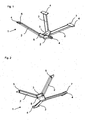
- Fig. 1
- eine perspektivische Draufsicht einer erfindungsgemäßen Ausführungsform der Diagonalstrebenvorrichtung,
- Fig. 2
- eine perspektivische Ansicht von unten auf eine erfindungsgemäße Ausführungsform der Diagonalstrebenvorrichtung.
- Die erfindungsgemäße Diagonalstrebenvorrichtung bezieht sich auf eine beispielhaft in den Figuren dargestellte sogenannte Fachwerkskonstruktion.
- Die Diagonalstrebenvorrichtung 1 besteht aus vier pultrudierten FVK-Profilstreben 2, die über einen zentralen Leichtmetallgussknoten 3 miteinander verbunden sind. Selbstverständlich ist eine andere Strebenanzahl, etwa sechs Streben, möglich. Die zur Anbindung an einen Kraftfahrzeug-Unterbau vorgesehenen Anbindungsknotenelemente 4 bestehen ebenfalls aus einem Leichtmetallmaterial. Die so gestaltete Diagonalstrebenvorrichtung 1 kann am Unterboden in der Montage oder auch schon im Rohbau befestigt werden. Dies wird durch die gegossenen Anbindungsknotenelemente 4 ermöglicht, die dazu entsprechende Fügehilfsmittel aufweisen können.
- Durch den Einsatz eines Leichtmetallmaterials zur Schaffung der Knoten 3,4 kann der Gewichtsvorteil der FVK-Streben 2 erhalten bleiben. Leichtmetallmaterialien sind Leichtmetalle und Legierungen mit einer Dichte unter 5 g/cm3. Vor allem Aluminium, Magnesium, Titan sowie in geringem Umfang Beryllium und Lithium finden technischen Einsatz. Sowohl für Aluminium- als auch Magnesiumlegierungen lassen sich im Druckguss Bauteile endabmessungsnah ohne kostenintensive Nachbearbeitung fertigen. Eine spanende Nachbearbeitung ist möglich.
- Die in den Figuren gezeigte Diagonalstrebenvorrichtung 1 kann zur Aussteifung der Karosserie an einem Unterboden eines Kraftfahrzeugs angeordnet werden, wobei das Zentralknotenelement 3 der Diagonalstrebenvorrichtung 1 unter dem Unterboden in einer vertikalen Längsmittelebene des Kraftfahrzeugs angeordnet wird und die Diagonalstrebenvorrichtung 1 mittels der Anbindungsknotenelemente 4 mit dem Unterboden in der Montage oder im Rohbau vernietet, verschraubt, geklebt, geclincht und/oder verschweißt wird.
- Die Diagonalstrebenvorrichtung 1 in den Figuren weist vier Streben 2 aus einem faserverstärkten Kunststoffverbundmaterial auf, bei denen es sich um FVK-Pultrusionsprofile 2 handelt, die einen Faseranteil bis zu 70 % haben können und die sich von dem Zentralknotenelement 3 X-förmig und geneigt weg erstrecken, so dass die von dem Zentralknotenelement 3 abgewandten Enden der Streben 2, an denen die Anbindungsknotenelemente 4 vorliegen, eine Ebene aufspannen, die von dem Zentralknotenelement 3 beabstandet ist.
- Dadurch, dass die Knotenelemente 3,4 an die Endabschnitte der Streben 2 angegossen sind, wird eine stoffschlüssige Verbindung bereitgestellt. Je nach Gestaltung der Knotenelemente 3,4 bezüglich der Strebenanordnung und auch in Bezug auf die vorgesehene Karosserieanbindung genügt es, wenn die Knotenelemente 3,4 lediglich an die Endabschnitte der Streben 2 angegossen sind, die Endabschnitte der Streben 2 können aber auch in das Zentralknotenelement 3 und/oder die Anbindungsknotenelemente 4 eingegossen sein, um die Verbindung zu stärken. Es kann sich aber auch ein Abschnitt des jeweiligen Gussknotens 3,4 in das Innere eines als Hohlprofil ausgeführten Streben-Endabschnitts erstrecken, so dass das Zentralknotenelement 3 und/oder das Anbindungsknotenelement 4 teilweise in die Streben-Endabschnitte eingegossen sind.
- Die Gussverbindung kann durch Durchbrüche und/oder Strukturen verstärkt werden, die die Streben 2 an ihren Endabschnitten aufweisen können und die durch das Gussmaterial der Gussverbindung formschlüssig durchdrungen und/oder umgeben werden.
- Ferner ist zum Schutz der FVK-Streben 2 vor Wärmeeintrag der Leichtmetallschmelze während des Angießens, da die Schmelzbereiche der Leichtmetallschmelze zwischen 400 und 660 °C liegen, denkbar, dass die Streben 2 zumindest an ihren Endabschnitten, an denen die Gussverbindung vorgesehen ist, mit einer thermisch isolierenden Beschichtung und/oder einer metallischen Beschichtung versehen sind.
- Eine Beschichtung der Endabschnitte der Streben 2 kann auch zur Haftverbesserung beitragen, indem die Beschichtung eine strukturierte Oberfläche bereitstellt, die eine Verklammerung des an die Streben 2 angegossenen Knotenelementematerials erlaubt.
- Die Anbindungsknotenelemente 4 weisen gegebenenfalls Fügehilfsmittel auf, mittels derer die Diagonalstrebenvorrichtung 1 leicht an einen Unterboden gefügt werden kann, der in diesem Falle den Anbindungsknotenelementen 4 entsprechende Fügestellen aufweisen sollte. Als Fügehilfsmittel kommen Bohrungen 7 oder Inserts, mit oder ohne Gewinde in den Anbindungsknotenelementen 4 in Frage, die ein Fügen mit Nieten oder Schrauben gestatten. Denkbar ist aber auch, dass die Anbindungsknotenelemente 4 zum Kleben oder Schweißen vorgesehene Flächen bereitstellen. Eine andere Fügemöglichkeit für die Anbindungsknotenelemente 4 liegt in der Ausbildung von Clinchelementen 6, die eine druckknopfähnliche Form aufweisen und mit einem korrespondierenden Gegenelement (an dem Unterboden) eine form- und kraftschlüssige Verbindung eingehen.
- Die verschiedenen Anbindungsknotenelemente 4 einer Diagonalstrebenvorrichtung 1 können dabei unterschiedliche Fügehilfsmittel aufweisen.
- Das Zentralknotenelement 3 oder die Anbindungsknotenelemente 4 oder beide können zusätzlich durch eine kraftschlüssige Verbindung wie mittels Nieten oder Schrauben 5 mit den Streben 2 verbunden sein.
- Zur Herstellung der Diagonalstrebenvorrichtung 1 werden die benötigten FVK-Streben 2 vorzugsweise durch Pultrusion hergestellt und in ein Druckgusswerkzeug eingelegt. Das Druckgusswerkzeug weist für die auszubildenden Knotenelemente Kavitäten sowie Ausnehmungen für die einzulegenden Streben auf. Eine zentrale Kavität dient der Bildung des Zentralknotenelements 3. Die eingelegten Streben 2 ragen einenends an oder in die zentrale Kavität, so dass dort die Gussverbindung hergestellt werden kann. An den anderen Enden der Strebenausnehmungen befinden sich im Gusswerkzeug die zur Bildung der Anbindungsknotenelemente 4 vorgesehenen Kavitäten, an die oder in die sich die eingelegten Streben 2 erstrecken. Mit den eingelegten Streben 2 wird das Werkzeug geschlossen und ein Druckgussvorgang gestartet. Das geschmolzene Leichtmetallmaterial gelangt in die Kavitäten und bildet dort das Zentralknotenelement 3 und die Anbindungsknotenelemente 4 aus, wobei gleichzeitig der stoffschlüssige Verbund mit den Streben 2 entsteht. Nach Erstarrung der gegossenen Knotenelemente 3,4 kann die Diagonalstrebenvorrichtung 1 entnommen werden.
- Zum Schutz der FVK-Streben vor Wärmeschaden kann die mit der Schmelze eingeführte Wärme während des Druckgießens mittels eines Kühlsystems des Werkzeugs abgeführt werden.
Claims (13)
- Diagonalstrebenvorrichtung (1)
zur aussteifenden Anordnung an einem Unterboden eines Kraftfahrzeugs, wobei die Diagonalstrebenvorrichtung (1) eine Mehrzahl von Streben (2) aus einem faserverstärkten Kunststoffverbundmaterial umfasst,
die sich von einem Zentralknotenelement (3) weg erstrecken,
wobei jede Strebe (2) über ihr von dem Zentralknotenelement (3) abgewandtes Ende an dem Unterboden anbindbar ist,
dadurch gekennzeichnet, dass
ein Anbindungsknotenelement (4) an dem von dem Zentralknotenelement (3) abgewandten Ende jeder Strebe (2) zur Bereitstellung der Anbindung an dem Unterboden angeordnet ist, und
dass das Zentralknotenelement (3) und die Anbindungsknotenelemente (4) aus einem Leichtmetallmaterial ausgeführt und durch eine zumindest stoffschlüssige Gussverbindung mit den Streben (2) verbunden sind. - Diagonalstrebenvorrichtung (1) nach Anspruch 1,
dadurch gekennzeichnet, dass
das Zentralknotenelement (3) und/oder die Anbindungsknotenelemente (4) an die Endabschnitte der Streben (2) angegossen sind, und/oder die Endabschnitte der Streben (2) in das Zentralknotenelement (3) und/oder die Anbindungsknotenelemente (4) eingegossen sind, und/oder die Streben (2) zumindest an den Endabschnitten ein Hohlprofil aufweisen, in das das Zentralknotenelement (3) und/oder das Anbindungsknotenelement (4) eingegossen ist. - Diagonalstrebenvorrichtung (1) nach Anspruch 1 oder 2,
dadurch gekennzeichnet, dass
die Streben (2) an ihren Endabschnitten Durchbrüche und/oder Strukturen aufweisen, die durch das Gussmaterial der Gussverbindung formschlüssig durchdrungen und/oder umgeben werden. - Diagonalstrebenvorrichtung (1) nach zumindest einem der Ansprüche 1 bis 3,
dadurch gekennzeichnet, dass
die Streben (2) zumindest an ihren Endabschnitten, an denen die Gussverbindung vorgesehen ist, mit einer thermisch isolierenden Beschichtung und/oder einer metallischen Beschichtung versehen sind. - Diagonalstrebenvorrichtung (1) nach zumindest einem der Ansprüche 1 bis 4,
dadurch gekennzeichnet, dass
die Streben (2) zumindest an ihren Endabschnitten, an denen die Gussverbindung vorgesehen ist, mit einer haftverbessernden Beschichtung versehen sind, die insbesondere eine strukturierte Oberfläche bereitstellt. - Diagonalstrebenvorrichtung (1) nach zumindest einem der Ansprüche 1 bis 5,
dadurch gekennzeichnet, dass
die Diagonalstrebenvorrichtung (1) Fügehilfsmittel aufweist, mittels derer die Diagonalstrebenvorrichtung (1) an den Unterboden fügbar ist, wobei die Fügehilfsmittel an den Anbindungsknotenelementen (4) vorgesehen sind und Bohrungen, Inserts, Gewinde, Klebeflächen, Clinchelemente und/oder Schweißflächen umfassen. - Diagonalstrebenvorrichtung (1) nach zumindest einem der Ansprüche 1 bis 6,
dadurch gekennzeichnet, dass
dass das Zentralknotenelement (3) und/oder die Anbindungsknotenelemente (4) zusätzlich durch eine kraftschlüssige Verbindung insbesondere durch Nieten oder Schrauben (5) mit den Streben (2) verbunden sind. - Diagonalstrebenvorrichtung (1) nach zumindest einem der Ansprüche 1 bis 7,
dadurch gekennzeichnet, dass
die Streben (2) FVK-Pultrusionsprofile (2), insbesondere mit einem Faseranteil bis zu 70 %, bezogen auf das Geamtgewicht des FVK-Pultrusionsprofils (2), sind. - Diagonalstrebenvorrichtung (1) nach zumindest einem der Ansprüche 1 bis 8,
dadurch gekennzeichnet, dass
die Diagonalstrebenvorrichtung (1) bis zu vier Streben (2) umfasst, die insbesondere X-förmig an dem Zentralknotenelement (3) angeordnet sind, und/oder die in Bezug zueinander geneigt an dem Zentralknotenelement (3) angeordnet sind, so dass das Zentralknotenelement (3) von einer Ebene, die die Anbindungselemente (4) aufspannen, beabstandet ist. - Diagonalstrebenvorrichtung (1) nach zumindest einem der Ansprüche 1 bis 9,
dadurch gekennzeichnet, dass
das Leichtmetallmaterial ein Leichtmetall oder eine Leichtmetalllegierung ist. - Verfahren zur Herstellung einer Diagonalstrebenvorrichtung (1) nach zumindest einem der Ansprüche 1 bis 10,
umfassend die Schritte:- Bereitstellen der Mehrzahl an Streben (2) aus einem faserverstärkten Kunststoffverbundmaterial und Einlegen in ein Druckgusswerkzeug, wobei die Streben (2) mit jeweils einem ersten Endabschnitt nahe zueinander in einem zur Ausbildung des Zentralknotenelements (3) vorgesehenen Bereich in einer Kavität und mit ihren zweiten Endabschnitten beabstandet voneinander in jeweils einem zur Ausbildung der Anbindungsknotenelemente (4) vorgesehenen Bereich in einer Kavität zu liegen kommen,- Schließen des Druckgusswerkzeugs und Druckgießen eines geschmolzenen Leichtmetallmaterials in die Kavitäten, dabei Ausbilden des Zentralknotenelements (3) und der Anbindungsknotenelemente (4) und gleichzeitig stoffschlüssig Verbinden des Zentralknotenelements (3) und der Anbindungsknotenelemente (4) mit den Streben (2), und- Entnehmen der Diagonalstrebenvorrichtung (1). - Verfahren nach Anspruch 11,
umfassend den Schritt:- während des Druckgießens Abführen von Wärme mittels eines Kühlsystems des Druckgusswerkzeugs aus dem Druckgusswerkzeug. - Kraftfahrzeugunterboden, der durch eine Diagonalstrebenvorrichtung ausgesteift ist, die an dem Kraftfahrzeugunterboden angeordnet ist, indem die Diagonalstrebenvorrichtung eine Mehrzahl von Streben (2) aus einem faserverstärkten Kunststoffverbundmaterial umfasst, die sich von einem Zentralknotenelement (3) weg erstrecken, wobei jede Strebe (2) über ihr von dem Zentralknotenelement (3) abgewandtes Ende an dem Unterboden angebunden ist,
dadurch gekennzeichnet, dass
ein Anbindungsknotenelement (4) an dem von dem Zentralknotenelement (3) abgewandten Ende jeder Strebe (2) angeordnet und die Anbindung mit dem Unterboden unlösbar bereitstellt, und
dass das Zentralknotenelement (3) und die Anbindungsknotenelemente (4) aus einem Leichtmetallmaterial ausgeführt und durch eine zumindest stoffschlüssige Gussverbindung mit den Streben (2) verbunden sind.
Applications Claiming Priority (2)
| Application Number | Priority Date | Filing Date | Title |
|---|---|---|---|
| DE201010053346 DE102010053346B4 (de) | 2010-12-03 | 2010-12-03 | Diagonalstrebenvorrichtung, Verfahren zu ihrer Herstellung und mittels Diagonalstrebenvorrichtung verstärkter Kraftfahrzeugunterboden |
| PCT/EP2011/005149 WO2012072160A1 (de) | 2010-12-03 | 2011-10-13 | Diagonalstrebenvorrichtung, verfahren zu ihrer herstellung und mittels diagonalstrebenvorrichtung verstärkter kraftfahrzeugunterboden |
Publications (2)
| Publication Number | Publication Date |
|---|---|
| EP2646310A1 EP2646310A1 (de) | 2013-10-09 |
| EP2646310B1 true EP2646310B1 (de) | 2015-04-01 |
Family
ID=44860291
Family Applications (1)
| Application Number | Title | Priority Date | Filing Date |
|---|---|---|---|
| EP11773999.5A Not-in-force EP2646310B1 (de) | 2010-12-03 | 2011-10-13 | Diagonalstrebenvorrichtung, verfahren zu ihrer herstellung und mittels diagonalstrebenvorrichtung verstärkter kraftfahrzeugunterboden |
Country Status (6)
| Country | Link |
|---|---|
| US (1) | US9010848B2 (de) |
| EP (1) | EP2646310B1 (de) |
| JP (1) | JP5629835B2 (de) |
| CN (1) | CN103237714B (de) |
| DE (1) | DE102010053346B4 (de) |
| WO (1) | WO2012072160A1 (de) |
Families Citing this family (9)
| Publication number | Priority date | Publication date | Assignee | Title |
|---|---|---|---|---|
| DE102010053843A1 (de) * | 2010-12-08 | 2012-06-14 | Daimler Ag | Verbindungsanordnung |
| DE102011009442A1 (de) * | 2011-01-26 | 2012-07-26 | Daimler Ag | Diagonalstrebenvorrichtung, Verfahren zu ihrer Herstellung und mittels Diagonalstrebenvorrichtung verstärkter Kraftfahrzeugunterboden |
| DE102012024281B3 (de) * | 2012-12-12 | 2014-04-24 | Daimler Ag | Zug-Druck-Strebe in einer Unterbodenstruktur eines Straßenfahrzeugs |
| DE102013021403A1 (de) | 2013-12-18 | 2015-06-18 | Daimler Ag | Unterbodenaussteifungs- und Verkleidungsmodul, Herstellverfahren sowie Kraftfahrzeug-Unterboden und Montageverfahren |
| DE102015119396A1 (de) * | 2015-11-11 | 2017-05-11 | Dr. Ing. H.C. F. Porsche Aktiengesellschaft | Verbundbauteil und Verfahren zur Herstellung eines Verbundbauteils |
| DE102016214996A1 (de) | 2016-08-11 | 2018-02-15 | Bayerische Motoren Werke Aktiengesellschaft | Kraftfahrzeug |
| US10906596B2 (en) | 2018-01-09 | 2021-02-02 | Faurecia Automotive Composites | Structural part of a body in white of a vehicle and associated manufacturing method |
| FR3076804B1 (fr) * | 2018-01-15 | 2020-02-07 | Faurecia Automotive Composites | Piece structurelle pour caisse en blanc de vehicule et procede de fabrication associe |
| DE102021005060A1 (de) | 2021-10-08 | 2021-11-25 | Daimler Ag | Versteifungsstrebe für eine Fahrzeugkarosserie und Verfahren zu deren Herstellung |
Family Cites Families (57)
| Publication number | Priority date | Publication date | Assignee | Title |
|---|---|---|---|---|
| DE532831C (de) * | 1931-09-04 | Wirz Ernst | Kippbarer Rahmen fuer Ladebruecken von Lastkraftwagen | |
| US1186013A (en) * | 1912-05-11 | 1916-06-06 | James Tillinghast | Two-point suspension for automobiles. |
| US1483650A (en) * | 1922-09-18 | 1924-02-12 | Jr Elbert A Corbin | Vehicle body |
| US1591215A (en) * | 1923-04-23 | 1926-07-06 | George S Jacobs | Braced element |
| US1577060A (en) * | 1924-05-10 | 1926-03-16 | American Motor Body Corp | Chassis-frame construction |
| US1841510A (en) * | 1929-09-20 | 1932-01-19 | Manning & Co | Automobile frame |
| US1917894A (en) * | 1931-05-25 | 1933-07-11 | Hupp Motor Car Corp | Chassis frame construction |
| US2121007A (en) * | 1934-06-29 | 1938-06-21 | Packard Motor Car Co | Motor vehicle |
| US2174915A (en) * | 1934-07-14 | 1939-10-03 | Midland Steel Prod Co | Automobile frame |
| US2080748A (en) * | 1935-06-15 | 1937-05-18 | Chrysler Corp | Motor vehicle frame |
| US2141635A (en) * | 1935-10-15 | 1938-12-27 | Midland Steel Prod Co | Automobile frame |
| US2173515A (en) * | 1936-06-05 | 1939-09-19 | Midland Steel Prod Co | Vehicle frame and method of making same |
| US2173516A (en) * | 1936-08-26 | 1939-09-19 | Midland Steel Prod Co | Automobile frame |
| US2163694A (en) * | 1937-11-01 | 1939-06-27 | Studebaker Corp | Frame |
| US2177991A (en) * | 1938-04-01 | 1939-10-31 | Midland Steel Prod Co | Automobile frame and structural member |
| US2229371A (en) * | 1938-07-20 | 1941-01-21 | Gen Motors Corp | Frame |
| US2257835A (en) * | 1939-01-03 | 1941-10-07 | Packard Motor Car Co | Motor vehicle |
| BE468936A (de) * | 1940-01-11 | |||
| CH240088A (de) * | 1942-06-02 | 1945-11-30 | Ford Motor Co | Verfahren zur Herstellung eines Fahrzeugrahmens. |
| US2476664A (en) * | 1947-05-23 | 1949-07-19 | Paul F Humig | Spring suspension system and unit for vehicles |
| US2676030A (en) * | 1948-11-29 | 1954-04-20 | Smith Corp A O | Automobile frame |
| US2715041A (en) * | 1953-09-14 | 1955-08-09 | Emmett A Fierbaugh | Shock absorbing and suspension means for vehicle bodies |
| US2747887A (en) * | 1953-11-06 | 1956-05-29 | Smith Corp A O | Box frame bulkhead |
| US2739822A (en) * | 1954-06-18 | 1956-03-27 | Smith Corp A O | X-frame construction |
| US2835506A (en) * | 1956-04-26 | 1958-05-20 | Smith Corp A O | X-member frame |
| DE2355551C2 (de) * | 1973-11-07 | 1984-09-27 | Maschinenfabriken Bernard Krone Gmbh, 4441 Spelle | Rahmenaufbau für Kippfahrzeuge |
| AT354504B (de) * | 1975-05-10 | 1979-01-10 | Gewerk Eisenhuette Westfalia | Vortriebsschild fuer den tunnel- oder stollen- vortrieb u. dgl. |
| CH673988A5 (de) * | 1987-04-29 | 1990-04-30 | Walter Baiker Dipl Ing | |
| DE3942794A1 (de) * | 1989-12-23 | 1991-07-04 | Bayerische Motoren Werke Ag | Rahmenanordnung fuer ein kraftfahrzeug |
| JPH05338558A (ja) * | 1992-06-08 | 1993-12-21 | Toyota Autom Loom Works Ltd | 自動車用補強部材の取付構造 |
| US5507522A (en) * | 1994-03-03 | 1996-04-16 | The Budd Company | Hybrid frame rail |
| FR2737177B1 (fr) * | 1995-07-28 | 1997-09-05 | Vallourec Vitry | Berceau tubulaire pour vehicule automobile |
| DE69836259T2 (de) | 1997-08-21 | 2007-06-06 | Toray Industries, Inc. | Verbundmaterial aus leichtmetall und mit kohlenstofffasern verstärktem kunststoff |
| EP0900716B1 (de) * | 1997-09-06 | 2003-01-29 | Volkswagen Aktiengesellschaft | Tragstruktur eines Kraftfahrzeugs |
| US5975625A (en) * | 1997-10-17 | 1999-11-02 | Ford Motor Company | Automotive vehicle body having a plastic outer body and an inner metal frame |
| US6162133A (en) * | 1997-11-03 | 2000-12-19 | Peterson; Lane | Golf club head |
| FR2787389B1 (fr) * | 1998-12-17 | 2001-03-02 | Patrick Pascal Labbe | Element de suspension de roue, notamment pour vehicule automobile, et structure de suspension comportant un tel element |
| DE19943242C2 (de) * | 1999-09-10 | 2001-09-06 | Daimler Chrysler Ag | Bodenanlage für einen Kraftwagen |
| US9616951B2 (en) * | 2002-03-06 | 2017-04-11 | Deere & Company | Non-carburized components of track-type machines having a metallurgically bonded coating |
| DE10214372C1 (de) * | 2002-03-30 | 2003-07-31 | Bayerische Motoren Werke Ag | Kraftfahrzeug |
| JP2004155219A (ja) * | 2002-11-01 | 2004-06-03 | Fuji Heavy Ind Ltd | 自動車の車体後部構造 |
| US6905137B2 (en) | 2002-11-21 | 2005-06-14 | Volvo Trucks North America, Inc. | Composite cross member system |
| DE10347365A1 (de) * | 2003-10-11 | 2005-05-25 | Wilhelm Karmann Gmbh | Kraftfahrzeug |
| US7055837B2 (en) * | 2003-12-08 | 2006-06-06 | Eric Noble | Strut/shock crossmember |
| DE102004001060A1 (de) * | 2004-01-02 | 2005-08-04 | Wilhelm Karmann Gmbh | Kraftfahrzeug |
| DE102004018977B4 (de) * | 2004-04-20 | 2014-08-28 | Valmet Automotive Oy | Kraftfahrzeug |
| US7273230B2 (en) * | 2004-05-05 | 2007-09-25 | Toyota Technical Center Usa, Inc. | Tension shackle x-brace |
| US7806162B2 (en) * | 2005-05-19 | 2010-10-05 | Magna International Inc. | Controlled pressure casting |
| DE102006047511A1 (de) * | 2005-10-15 | 2007-04-19 | Zf Lenksysteme Gmbh | Achssystem |
| JP2007203896A (ja) * | 2006-02-02 | 2007-08-16 | Yamaha Motor Co Ltd | 車両の車体用補強装置 |
| CZ2008248A3 (cs) | 2007-04-24 | 2008-11-05 | Benteler Automobiltechnik Gmbh | Zpusob výroby pomocného rámu, motorového vozidla,jakož i pomocný rám motorového vozidla |
| BRPI0817967B1 (pt) * | 2007-10-19 | 2021-06-01 | Lord Corporation | Sistema de suspensão de unidade de potência auxiliar de controle de movimento de aeronave |
| DE102010020793A1 (de) | 2010-05-18 | 2011-02-17 | Daimler Ag | Verbindungsanordnung und Verfahren zu ihrer Herstellung |
| DE102011009442A1 (de) * | 2011-01-26 | 2012-07-26 | Daimler Ag | Diagonalstrebenvorrichtung, Verfahren zu ihrer Herstellung und mittels Diagonalstrebenvorrichtung verstärkter Kraftfahrzeugunterboden |
| US8439431B2 (en) * | 2011-05-31 | 2013-05-14 | Ford Global Technologies, Llc | Attachment bracket for connecting peripheral devices to a vehicle |
| US8534748B1 (en) * | 2012-06-26 | 2013-09-17 | Ford Global Technologies, Llc | Safety cross-brace structure for vehicles |
| EP2786921B1 (de) * | 2013-04-04 | 2017-09-20 | MAGNA STEYR Engineering AG & Co KG | Klebeverbindung eines ersten Hohlprofils mit einem zweiten Hohlprofil |
-
2010
- 2010-12-03 DE DE201010053346 patent/DE102010053346B4/de not_active Expired - Fee Related
-
2011
- 2011-10-13 US US13/990,118 patent/US9010848B2/en not_active Expired - Fee Related
- 2011-10-13 EP EP11773999.5A patent/EP2646310B1/de not_active Not-in-force
- 2011-10-13 JP JP2013541223A patent/JP5629835B2/ja not_active Expired - Fee Related
- 2011-10-13 WO PCT/EP2011/005149 patent/WO2012072160A1/de not_active Ceased
- 2011-10-13 CN CN201180058157.4A patent/CN103237714B/zh not_active Expired - Fee Related
Also Published As
| Publication number | Publication date |
|---|---|
| WO2012072160A1 (de) | 2012-06-07 |
| EP2646310A1 (de) | 2013-10-09 |
| CN103237714A (zh) | 2013-08-07 |
| DE102010053346B4 (de) | 2013-04-25 |
| US9010848B2 (en) | 2015-04-21 |
| JP2013544208A (ja) | 2013-12-12 |
| CN103237714B (zh) | 2016-03-30 |
| US20130249249A1 (en) | 2013-09-26 |
| JP5629835B2 (ja) | 2014-11-26 |
| DE102010053346A1 (de) | 2012-06-06 |
Similar Documents
| Publication | Publication Date | Title |
|---|---|---|
| DE102010053346B4 (de) | Diagonalstrebenvorrichtung, Verfahren zu ihrer Herstellung und mittels Diagonalstrebenvorrichtung verstärkter Kraftfahrzeugunterboden | |
| EP2668087B1 (de) | Diagonalstrebenvorrichtung, verfahren zu ihrer herstellung und mittels diagonalstrebenvorrichtung verstärkter kraftfahrzeugunterboden | |
| EP2990308B1 (de) | Achsträger für ein kraftfahrzeug sowie verfahren zur herstellung eines achsträgers | |
| EP2582565B1 (de) | Kraftfahrzeug mit einem chassisrahmen und einem fahrzeugaufbau | |
| EP2648965B1 (de) | Kraftfahrzeugkarosserie mit versteifungsstreben | |
| EP3224119B1 (de) | Verfahren zum verstärken eines bauelements eines kraftfahrzeug-fahrwerks | |
| DE102010050874B4 (de) | Kraftfahrzeugstrukturbauteil aus mittels eines Knotenelements verbundenen Halbzeug-Bauteilen und Herstellungsverfahren | |
| EP2513495B1 (de) | Krafteinleitungsbeschlag für leichtbaukomponenten | |
| WO2013167114A1 (de) | Modulares achskonzept für ein kraftfahrzeug mit elektrischem antrieb | |
| DE102015111749A1 (de) | Batterieeinrichtung und Verfahren | |
| DE102011120180A1 (de) | Karosseriebauteil | |
| EP2888151B1 (de) | Achsträger für ein kraftfahrzeug | |
| DE102008060794A1 (de) | Bauteil aus einer Magnesiumlegierung und Verfahren zu dessen Herstellung | |
| EP3360761B1 (de) | Schweller für ein kraftfahrzeug | |
| WO2013092119A1 (de) | Aufbau für einen kraftwagen, insbesondere einen personenkraftwagen, sowie verfahren zum herstellen eines solchen aufbaus | |
| EP2888153B1 (de) | Lageranordnung und achsträger für ein kraftfahrzeug | |
| EP3162699B1 (de) | Strukturanordnung, luft- oder raumfahrzeug und verfahren zum herstellen einer strukturanordnung | |
| DE102013017269A1 (de) | Karosseriebauteil und Kraftfahrzeug mit dem Karosseriebauteil | |
| WO2024121336A1 (de) | Unterbodenschutz für kraftfahrzeuge, kraftfahrzeug mit unterbodenschutz und verfahren zum herstellen eines unterbodenschutzes | |
| DE102016011304A1 (de) | Sitzstrukturelement für einen Kraftfahrzeugsitz, Verfahren zu dessen Herstellung und Kraftfahrzeugsitz mit solchem Sitzstrukturelement | |
| EP2617629B1 (de) | Karosserieknoten | |
| DE102014204369A1 (de) | Verfahren zum Herstellen einer tragenden Fahrzeugstruktur | |
| DE102010023073A1 (de) | Strukturbauteil einer Kraftfahrzeugkarosserie | |
| DE102012001041A1 (de) | Querträgerelement für eine Karosseriestruktur eines Personenkraftwagens | |
| EP3725652B1 (de) | Verfahren zur reparatur einer fahrzeugkarosserie |
Legal Events
| Date | Code | Title | Description |
|---|---|---|---|
| PUAI | Public reference made under article 153(3) epc to a published international application that has entered the european phase |
Free format text: ORIGINAL CODE: 0009012 |
|
| 17P | Request for examination filed |
Effective date: 20130508 |
|
| AK | Designated contracting states |
Kind code of ref document: A1 Designated state(s): AL AT BE BG CH CY CZ DE DK EE ES FI FR GB GR HR HU IE IS IT LI LT LU LV MC MK MT NL NO PL PT RO RS SE SI SK SM TR |
|
| DAX | Request for extension of the european patent (deleted) | ||
| GRAP | Despatch of communication of intention to grant a patent |
Free format text: ORIGINAL CODE: EPIDOSNIGR1 |
|
| INTG | Intention to grant announced |
Effective date: 20141016 |
|
| GRAS | Grant fee paid |
Free format text: ORIGINAL CODE: EPIDOSNIGR3 |
|
| GRAA | (expected) grant |
Free format text: ORIGINAL CODE: 0009210 |
|
| AK | Designated contracting states |
Kind code of ref document: B1 Designated state(s): AL AT BE BG CH CY CZ DE DK EE ES FI FR GB GR HR HU IE IS IT LI LT LU LV MC MK MT NL NO PL PT RO RS SE SI SK SM TR |
|
| REG | Reference to a national code |
Ref country code: GB Ref legal event code: FG4D Free format text: NOT ENGLISH |
|
| REG | Reference to a national code |
Ref country code: CH Ref legal event code: EP |
|
| REG | Reference to a national code |
Ref country code: IE Ref legal event code: FG4D Free format text: LANGUAGE OF EP DOCUMENT: GERMAN |
|
| REG | Reference to a national code |
Ref country code: AT Ref legal event code: REF Ref document number: 718897 Country of ref document: AT Kind code of ref document: T Effective date: 20150515 |
|
| REG | Reference to a national code |
Ref country code: DE Ref legal event code: R096 Ref document number: 502011006466 Country of ref document: DE Effective date: 20150521 |
|
| REG | Reference to a national code |
Ref country code: NL Ref legal event code: VDEP Effective date: 20150401 |
|
| REG | Reference to a national code |
Ref country code: LT Ref legal event code: MG4D |
|
| PG25 | Lapsed in a contracting state [announced via postgrant information from national office to epo] |
Ref country code: NL Free format text: LAPSE BECAUSE OF FAILURE TO SUBMIT A TRANSLATION OF THE DESCRIPTION OR TO PAY THE FEE WITHIN THE PRESCRIBED TIME-LIMIT Effective date: 20150401 |
|
| PG25 | Lapsed in a contracting state [announced via postgrant information from national office to epo] |
Ref country code: HR Free format text: LAPSE BECAUSE OF FAILURE TO SUBMIT A TRANSLATION OF THE DESCRIPTION OR TO PAY THE FEE WITHIN THE PRESCRIBED TIME-LIMIT Effective date: 20150401 Ref country code: LT Free format text: LAPSE BECAUSE OF FAILURE TO SUBMIT A TRANSLATION OF THE DESCRIPTION OR TO PAY THE FEE WITHIN THE PRESCRIBED TIME-LIMIT Effective date: 20150401 Ref country code: FI Free format text: LAPSE BECAUSE OF FAILURE TO SUBMIT A TRANSLATION OF THE DESCRIPTION OR TO PAY THE FEE WITHIN THE PRESCRIBED TIME-LIMIT Effective date: 20150401 Ref country code: NO Free format text: LAPSE BECAUSE OF FAILURE TO SUBMIT A TRANSLATION OF THE DESCRIPTION OR TO PAY THE FEE WITHIN THE PRESCRIBED TIME-LIMIT Effective date: 20150701 Ref country code: ES Free format text: LAPSE BECAUSE OF FAILURE TO SUBMIT A TRANSLATION OF THE DESCRIPTION OR TO PAY THE FEE WITHIN THE PRESCRIBED TIME-LIMIT Effective date: 20150401 Ref country code: PT Free format text: LAPSE BECAUSE OF FAILURE TO SUBMIT A TRANSLATION OF THE DESCRIPTION OR TO PAY THE FEE WITHIN THE PRESCRIBED TIME-LIMIT Effective date: 20150803 Ref country code: CZ Free format text: LAPSE BECAUSE OF FAILURE TO SUBMIT A TRANSLATION OF THE DESCRIPTION OR TO PAY THE FEE WITHIN THE PRESCRIBED TIME-LIMIT Effective date: 20150401 |
|
| REG | Reference to a national code |
Ref country code: FR Ref legal event code: PLFP Year of fee payment: 5 |
|
| PG25 | Lapsed in a contracting state [announced via postgrant information from national office to epo] |
Ref country code: RS Free format text: LAPSE BECAUSE OF FAILURE TO SUBMIT A TRANSLATION OF THE DESCRIPTION OR TO PAY THE FEE WITHIN THE PRESCRIBED TIME-LIMIT Effective date: 20150401 Ref country code: GR Free format text: LAPSE BECAUSE OF FAILURE TO SUBMIT A TRANSLATION OF THE DESCRIPTION OR TO PAY THE FEE WITHIN THE PRESCRIBED TIME-LIMIT Effective date: 20150702 Ref country code: IS Free format text: LAPSE BECAUSE OF FAILURE TO SUBMIT A TRANSLATION OF THE DESCRIPTION OR TO PAY THE FEE WITHIN THE PRESCRIBED TIME-LIMIT Effective date: 20150801 Ref country code: LV Free format text: LAPSE BECAUSE OF FAILURE TO SUBMIT A TRANSLATION OF THE DESCRIPTION OR TO PAY THE FEE WITHIN THE PRESCRIBED TIME-LIMIT Effective date: 20150401 |
|
| REG | Reference to a national code |
Ref country code: DE Ref legal event code: R097 Ref document number: 502011006466 Country of ref document: DE |
|
| PG25 | Lapsed in a contracting state [announced via postgrant information from national office to epo] |
Ref country code: EE Free format text: LAPSE BECAUSE OF FAILURE TO SUBMIT A TRANSLATION OF THE DESCRIPTION OR TO PAY THE FEE WITHIN THE PRESCRIBED TIME-LIMIT Effective date: 20150401 Ref country code: DK Free format text: LAPSE BECAUSE OF FAILURE TO SUBMIT A TRANSLATION OF THE DESCRIPTION OR TO PAY THE FEE WITHIN THE PRESCRIBED TIME-LIMIT Effective date: 20150401 |
|
| PLBE | No opposition filed within time limit |
Free format text: ORIGINAL CODE: 0009261 |
|
| STAA | Information on the status of an ep patent application or granted ep patent |
Free format text: STATUS: NO OPPOSITION FILED WITHIN TIME LIMIT |
|
| PG25 | Lapsed in a contracting state [announced via postgrant information from national office to epo] |
Ref country code: SK Free format text: LAPSE BECAUSE OF FAILURE TO SUBMIT A TRANSLATION OF THE DESCRIPTION OR TO PAY THE FEE WITHIN THE PRESCRIBED TIME-LIMIT Effective date: 20150401 Ref country code: PL Free format text: LAPSE BECAUSE OF FAILURE TO SUBMIT A TRANSLATION OF THE DESCRIPTION OR TO PAY THE FEE WITHIN THE PRESCRIBED TIME-LIMIT Effective date: 20150401 Ref country code: RO Free format text: LAPSE BECAUSE OF NON-PAYMENT OF DUE FEES Effective date: 20150401 |
|
| 26N | No opposition filed |
Effective date: 20160105 |
|
| PG25 | Lapsed in a contracting state [announced via postgrant information from national office to epo] |
Ref country code: IT Free format text: LAPSE BECAUSE OF FAILURE TO SUBMIT A TRANSLATION OF THE DESCRIPTION OR TO PAY THE FEE WITHIN THE PRESCRIBED TIME-LIMIT Effective date: 20150401 |
|
| PG25 | Lapsed in a contracting state [announced via postgrant information from national office to epo] |
Ref country code: SI Free format text: LAPSE BECAUSE OF FAILURE TO SUBMIT A TRANSLATION OF THE DESCRIPTION OR TO PAY THE FEE WITHIN THE PRESCRIBED TIME-LIMIT Effective date: 20150401 Ref country code: LU Free format text: LAPSE BECAUSE OF FAILURE TO SUBMIT A TRANSLATION OF THE DESCRIPTION OR TO PAY THE FEE WITHIN THE PRESCRIBED TIME-LIMIT Effective date: 20151013 |
|
| REG | Reference to a national code |
Ref country code: CH Ref legal event code: PL |
|
| PG25 | Lapsed in a contracting state [announced via postgrant information from national office to epo] |
Ref country code: MC Free format text: LAPSE BECAUSE OF FAILURE TO SUBMIT A TRANSLATION OF THE DESCRIPTION OR TO PAY THE FEE WITHIN THE PRESCRIBED TIME-LIMIT Effective date: 20150401 |
|
| REG | Reference to a national code |
Ref country code: IE Ref legal event code: MM4A |
|
| PG25 | Lapsed in a contracting state [announced via postgrant information from national office to epo] |
Ref country code: LI Free format text: LAPSE BECAUSE OF NON-PAYMENT OF DUE FEES Effective date: 20151031 Ref country code: CH Free format text: LAPSE BECAUSE OF NON-PAYMENT OF DUE FEES Effective date: 20151031 |
|
| REG | Reference to a national code |
Ref country code: FR Ref legal event code: PLFP Year of fee payment: 6 |
|
| PG25 | Lapsed in a contracting state [announced via postgrant information from national office to epo] |
Ref country code: IE Free format text: LAPSE BECAUSE OF NON-PAYMENT OF DUE FEES Effective date: 20151013 |
|
| PGFP | Annual fee paid to national office [announced via postgrant information from national office to epo] |
Ref country code: FR Payment date: 20161027 Year of fee payment: 6 Ref country code: GB Payment date: 20161028 Year of fee payment: 6 |
|
| PGFP | Annual fee paid to national office [announced via postgrant information from national office to epo] |
Ref country code: DE Payment date: 20170102 Year of fee payment: 6 |
|
| PG25 | Lapsed in a contracting state [announced via postgrant information from national office to epo] |
Ref country code: BG Free format text: LAPSE BECAUSE OF FAILURE TO SUBMIT A TRANSLATION OF THE DESCRIPTION OR TO PAY THE FEE WITHIN THE PRESCRIBED TIME-LIMIT Effective date: 20150401 Ref country code: HU Free format text: LAPSE BECAUSE OF FAILURE TO SUBMIT A TRANSLATION OF THE DESCRIPTION OR TO PAY THE FEE WITHIN THE PRESCRIBED TIME-LIMIT; INVALID AB INITIO Effective date: 20111013 Ref country code: SM Free format text: LAPSE BECAUSE OF FAILURE TO SUBMIT A TRANSLATION OF THE DESCRIPTION OR TO PAY THE FEE WITHIN THE PRESCRIBED TIME-LIMIT Effective date: 20150401 |
|
| PG25 | Lapsed in a contracting state [announced via postgrant information from national office to epo] |
Ref country code: CY Free format text: LAPSE BECAUSE OF FAILURE TO SUBMIT A TRANSLATION OF THE DESCRIPTION OR TO PAY THE FEE WITHIN THE PRESCRIBED TIME-LIMIT Effective date: 20150401 Ref country code: SE Free format text: LAPSE BECAUSE OF FAILURE TO SUBMIT A TRANSLATION OF THE DESCRIPTION OR TO PAY THE FEE WITHIN THE PRESCRIBED TIME-LIMIT Effective date: 20150401 |
|
| PG25 | Lapsed in a contracting state [announced via postgrant information from national office to epo] |
Ref country code: BE Free format text: LAPSE BECAUSE OF NON-PAYMENT OF DUE FEES Effective date: 20151031 |
|
| PG25 | Lapsed in a contracting state [announced via postgrant information from national office to epo] |
Ref country code: MT Free format text: LAPSE BECAUSE OF FAILURE TO SUBMIT A TRANSLATION OF THE DESCRIPTION OR TO PAY THE FEE WITHIN THE PRESCRIBED TIME-LIMIT Effective date: 20150401 |
|
| REG | Reference to a national code |
Ref country code: AT Ref legal event code: MM01 Ref document number: 718897 Country of ref document: AT Kind code of ref document: T Effective date: 20161013 |
|
| PG25 | Lapsed in a contracting state [announced via postgrant information from national office to epo] |
Ref country code: AT Free format text: LAPSE BECAUSE OF NON-PAYMENT OF DUE FEES Effective date: 20161013 |
|
| REG | Reference to a national code |
Ref country code: DE Ref legal event code: R119 Ref document number: 502011006466 Country of ref document: DE |
|
| GBPC | Gb: european patent ceased through non-payment of renewal fee |
Effective date: 20171013 |
|
| PG25 | Lapsed in a contracting state [announced via postgrant information from national office to epo] |
Ref country code: TR Free format text: LAPSE BECAUSE OF FAILURE TO SUBMIT A TRANSLATION OF THE DESCRIPTION OR TO PAY THE FEE WITHIN THE PRESCRIBED TIME-LIMIT Effective date: 20150401 Ref country code: MK Free format text: LAPSE BECAUSE OF FAILURE TO SUBMIT A TRANSLATION OF THE DESCRIPTION OR TO PAY THE FEE WITHIN THE PRESCRIBED TIME-LIMIT Effective date: 20150401 |
|
| REG | Reference to a national code |
Ref country code: FR Ref legal event code: ST Effective date: 20180629 |
|
| PG25 | Lapsed in a contracting state [announced via postgrant information from national office to epo] |
Ref country code: DE Free format text: LAPSE BECAUSE OF NON-PAYMENT OF DUE FEES Effective date: 20180501 Ref country code: GB Free format text: LAPSE BECAUSE OF NON-PAYMENT OF DUE FEES Effective date: 20171013 |
|
| PG25 | Lapsed in a contracting state [announced via postgrant information from national office to epo] |
Ref country code: FR Free format text: LAPSE BECAUSE OF NON-PAYMENT OF DUE FEES Effective date: 20171031 |
|
| PG25 | Lapsed in a contracting state [announced via postgrant information from national office to epo] |
Ref country code: AL Free format text: LAPSE BECAUSE OF FAILURE TO SUBMIT A TRANSLATION OF THE DESCRIPTION OR TO PAY THE FEE WITHIN THE PRESCRIBED TIME-LIMIT Effective date: 20150401 |