EP2646186B1 - Fertiggepresste / fertiggesinterte schneidplatte und verfahren zu deren herstellung - Google Patents
Fertiggepresste / fertiggesinterte schneidplatte und verfahren zu deren herstellung Download PDFInfo
- Publication number
- EP2646186B1 EP2646186B1 EP11790781.6A EP11790781A EP2646186B1 EP 2646186 B1 EP2646186 B1 EP 2646186B1 EP 11790781 A EP11790781 A EP 11790781A EP 2646186 B1 EP2646186 B1 EP 2646186B1
- Authority
- EP
- European Patent Office
- Prior art keywords
- sintering
- cutting
- cutting plate
- blank
- faces
- Prior art date
- Legal status (The legal status is an assumption and is not a legal conclusion. Google has not performed a legal analysis and makes no representation as to the accuracy of the status listed.)
- Not-in-force
Links
- 238000004519 manufacturing process Methods 0.000 title claims description 10
- 238000005520 cutting process Methods 0.000 claims description 56
- 238000005245 sintering Methods 0.000 claims description 38
- 239000000463 material Substances 0.000 claims description 27
- 239000000919 ceramic Substances 0.000 claims description 16
- 238000003825 pressing Methods 0.000 claims description 15
- 238000000034 method Methods 0.000 claims description 10
- 230000002787 reinforcement Effects 0.000 claims description 8
- 229910052581 Si3N4 Inorganic materials 0.000 claims description 7
- MCMNRKCIXSYSNV-UHFFFAOYSA-N ZrO2 Inorganic materials O=[Zr]=O MCMNRKCIXSYSNV-UHFFFAOYSA-N 0.000 claims description 6
- 238000003754 machining Methods 0.000 claims description 5
- 238000009434 installation Methods 0.000 claims description 3
- 238000012545 processing Methods 0.000 claims description 3
- PNEYBMLMFCGWSK-UHFFFAOYSA-N aluminium oxide Inorganic materials [O-2].[O-2].[O-2].[Al+3].[Al+3] PNEYBMLMFCGWSK-UHFFFAOYSA-N 0.000 description 8
- 229910052593 corundum Inorganic materials 0.000 description 8
- 229910001845 yogo sapphire Inorganic materials 0.000 description 8
- 229910052799 carbon Inorganic materials 0.000 description 6
- 238000000227 grinding Methods 0.000 description 4
- 230000008901 benefit Effects 0.000 description 3
- 210000000078 claw Anatomy 0.000 description 3
- 239000008187 granular material Substances 0.000 description 3
- 229920001817 Agar Polymers 0.000 description 2
- OKTJSMMVPCPJKN-UHFFFAOYSA-N Carbon Chemical compound [C] OKTJSMMVPCPJKN-UHFFFAOYSA-N 0.000 description 2
- 229910003460 diamond Inorganic materials 0.000 description 2
- 239000010432 diamond Substances 0.000 description 2
- 238000005259 measurement Methods 0.000 description 2
- 239000002184 metal Substances 0.000 description 2
- 229910052751 metal Inorganic materials 0.000 description 2
- 238000012805 post-processing Methods 0.000 description 2
- 239000000843 powder Substances 0.000 description 2
- 238000002360 preparation method Methods 0.000 description 2
- 230000009467 reduction Effects 0.000 description 2
- 206010022528 Interactions Diseases 0.000 description 1
- 229910003564 SiAlON Inorganic materials 0.000 description 1
- 239000000654 additive Substances 0.000 description 1
- 238000005056 compaction Methods 0.000 description 1
- 239000002131 composite material Substances 0.000 description 1
- 238000010276 construction Methods 0.000 description 1
- -1 ferrous metals Chemical class 0.000 description 1
- 239000007770 graphite material Substances 0.000 description 1
- 239000012535 impurity Substances 0.000 description 1
- 238000009413 insulation Methods 0.000 description 1
- 230000003993 interaction Effects 0.000 description 1
- 150000002739 metals Chemical class 0.000 description 1
- 239000004033 plastic Substances 0.000 description 1
- 229920003023 plastic Polymers 0.000 description 1
- 230000008569 process Effects 0.000 description 1
- 230000001105 regulatory effect Effects 0.000 description 1
- 230000000284 resting effect Effects 0.000 description 1
- HQVNEWCFYHHQES-UHFFFAOYSA-N silicon nitride Chemical compound N12[Si]34N5[Si]62N3[Si]51N64 HQVNEWCFYHHQES-UHFFFAOYSA-N 0.000 description 1
- 239000002023 wood Substances 0.000 description 1
Images
Classifications
-
- B—PERFORMING OPERATIONS; TRANSPORTING
- B23—MACHINE TOOLS; METAL-WORKING NOT OTHERWISE PROVIDED FOR
- B23B—TURNING; BORING
- B23B27/00—Tools for turning or boring machines; Tools of a similar kind in general; Accessories therefor
- B23B27/14—Cutting tools of which the bits or tips or cutting inserts are of special material
- B23B27/148—Composition of the cutting inserts
-
- B—PERFORMING OPERATIONS; TRANSPORTING
- B23—MACHINE TOOLS; METAL-WORKING NOT OTHERWISE PROVIDED FOR
- B23B—TURNING; BORING
- B23B27/00—Tools for turning or boring machines; Tools of a similar kind in general; Accessories therefor
- B23B27/14—Cutting tools of which the bits or tips or cutting inserts are of special material
-
- B—PERFORMING OPERATIONS; TRANSPORTING
- B23—MACHINE TOOLS; METAL-WORKING NOT OTHERWISE PROVIDED FOR
- B23B—TURNING; BORING
- B23B27/00—Tools for turning or boring machines; Tools of a similar kind in general; Accessories therefor
- B23B27/14—Cutting tools of which the bits or tips or cutting inserts are of special material
- B23B27/141—Specially shaped plate-like cutting inserts, i.e. length greater or equal to width, width greater than or equal to thickness
-
- B—PERFORMING OPERATIONS; TRANSPORTING
- B23—MACHINE TOOLS; METAL-WORKING NOT OTHERWISE PROVIDED FOR
- B23P—METAL-WORKING NOT OTHERWISE PROVIDED FOR; COMBINED OPERATIONS; UNIVERSAL MACHINE TOOLS
- B23P15/00—Making specific metal objects by operations not covered by a single other subclass or a group in this subclass
- B23P15/28—Making specific metal objects by operations not covered by a single other subclass or a group in this subclass cutting tools
-
- B—PERFORMING OPERATIONS; TRANSPORTING
- B23—MACHINE TOOLS; METAL-WORKING NOT OTHERWISE PROVIDED FOR
- B23P—METAL-WORKING NOT OTHERWISE PROVIDED FOR; COMBINED OPERATIONS; UNIVERSAL MACHINE TOOLS
- B23P15/00—Making specific metal objects by operations not covered by a single other subclass or a group in this subclass
- B23P15/28—Making specific metal objects by operations not covered by a single other subclass or a group in this subclass cutting tools
- B23P15/32—Making specific metal objects by operations not covered by a single other subclass or a group in this subclass cutting tools twist-drills
-
- B—PERFORMING OPERATIONS; TRANSPORTING
- B28—WORKING CEMENT, CLAY, OR STONE
- B28B—SHAPING CLAY OR OTHER CERAMIC COMPOSITIONS; SHAPING SLAG; SHAPING MIXTURES CONTAINING CEMENTITIOUS MATERIAL, e.g. PLASTER
- B28B11/00—Apparatus or processes for treating or working the shaped or preshaped articles
- B28B11/12—Apparatus or processes for treating or working the shaped or preshaped articles for removing parts of the articles by cutting
-
- C—CHEMISTRY; METALLURGY
- C04—CEMENTS; CONCRETE; ARTIFICIAL STONE; CERAMICS; REFRACTORIES
- C04B—LIME, MAGNESIA; SLAG; CEMENTS; COMPOSITIONS THEREOF, e.g. MORTARS, CONCRETE OR LIKE BUILDING MATERIALS; ARTIFICIAL STONE; CERAMICS; REFRACTORIES; TREATMENT OF NATURAL STONE
- C04B35/00—Shaped ceramic products characterised by their composition; Ceramics compositions; Processing powders of inorganic compounds preparatory to the manufacturing of ceramic products
- C04B35/01—Shaped ceramic products characterised by their composition; Ceramics compositions; Processing powders of inorganic compounds preparatory to the manufacturing of ceramic products based on oxide ceramics
- C04B35/10—Shaped ceramic products characterised by their composition; Ceramics compositions; Processing powders of inorganic compounds preparatory to the manufacturing of ceramic products based on oxide ceramics based on aluminium oxide
- C04B35/111—Fine ceramics
- C04B35/117—Composites
-
- C—CHEMISTRY; METALLURGY
- C04—CEMENTS; CONCRETE; ARTIFICIAL STONE; CERAMICS; REFRACTORIES
- C04B—LIME, MAGNESIA; SLAG; CEMENTS; COMPOSITIONS THEREOF, e.g. MORTARS, CONCRETE OR LIKE BUILDING MATERIALS; ARTIFICIAL STONE; CERAMICS; REFRACTORIES; TREATMENT OF NATURAL STONE
- C04B35/00—Shaped ceramic products characterised by their composition; Ceramics compositions; Processing powders of inorganic compounds preparatory to the manufacturing of ceramic products
- C04B35/01—Shaped ceramic products characterised by their composition; Ceramics compositions; Processing powders of inorganic compounds preparatory to the manufacturing of ceramic products based on oxide ceramics
- C04B35/10—Shaped ceramic products characterised by their composition; Ceramics compositions; Processing powders of inorganic compounds preparatory to the manufacturing of ceramic products based on oxide ceramics based on aluminium oxide
- C04B35/111—Fine ceramics
- C04B35/117—Composites
- C04B35/119—Composites with zirconium oxide
-
- C—CHEMISTRY; METALLURGY
- C04—CEMENTS; CONCRETE; ARTIFICIAL STONE; CERAMICS; REFRACTORIES
- C04B—LIME, MAGNESIA; SLAG; CEMENTS; COMPOSITIONS THEREOF, e.g. MORTARS, CONCRETE OR LIKE BUILDING MATERIALS; ARTIFICIAL STONE; CERAMICS; REFRACTORIES; TREATMENT OF NATURAL STONE
- C04B35/00—Shaped ceramic products characterised by their composition; Ceramics compositions; Processing powders of inorganic compounds preparatory to the manufacturing of ceramic products
- C04B35/515—Shaped ceramic products characterised by their composition; Ceramics compositions; Processing powders of inorganic compounds preparatory to the manufacturing of ceramic products based on non-oxide ceramics
- C04B35/58—Shaped ceramic products characterised by their composition; Ceramics compositions; Processing powders of inorganic compounds preparatory to the manufacturing of ceramic products based on non-oxide ceramics based on borides, nitrides, i.e. nitrides, oxynitrides, carbonitrides or oxycarbonitrides or silicides
- C04B35/584—Shaped ceramic products characterised by their composition; Ceramics compositions; Processing powders of inorganic compounds preparatory to the manufacturing of ceramic products based on non-oxide ceramics based on borides, nitrides, i.e. nitrides, oxynitrides, carbonitrides or oxycarbonitrides or silicides based on silicon nitride
-
- C—CHEMISTRY; METALLURGY
- C04—CEMENTS; CONCRETE; ARTIFICIAL STONE; CERAMICS; REFRACTORIES
- C04B—LIME, MAGNESIA; SLAG; CEMENTS; COMPOSITIONS THEREOF, e.g. MORTARS, CONCRETE OR LIKE BUILDING MATERIALS; ARTIFICIAL STONE; CERAMICS; REFRACTORIES; TREATMENT OF NATURAL STONE
- C04B35/00—Shaped ceramic products characterised by their composition; Ceramics compositions; Processing powders of inorganic compounds preparatory to the manufacturing of ceramic products
- C04B35/515—Shaped ceramic products characterised by their composition; Ceramics compositions; Processing powders of inorganic compounds preparatory to the manufacturing of ceramic products based on non-oxide ceramics
- C04B35/58—Shaped ceramic products characterised by their composition; Ceramics compositions; Processing powders of inorganic compounds preparatory to the manufacturing of ceramic products based on non-oxide ceramics based on borides, nitrides, i.e. nitrides, oxynitrides, carbonitrides or oxycarbonitrides or silicides
- C04B35/597—Shaped ceramic products characterised by their composition; Ceramics compositions; Processing powders of inorganic compounds preparatory to the manufacturing of ceramic products based on non-oxide ceramics based on borides, nitrides, i.e. nitrides, oxynitrides, carbonitrides or oxycarbonitrides or silicides based on silicon oxynitride, e.g. SIALONS
-
- C—CHEMISTRY; METALLURGY
- C04—CEMENTS; CONCRETE; ARTIFICIAL STONE; CERAMICS; REFRACTORIES
- C04B—LIME, MAGNESIA; SLAG; CEMENTS; COMPOSITIONS THEREOF, e.g. MORTARS, CONCRETE OR LIKE BUILDING MATERIALS; ARTIFICIAL STONE; CERAMICS; REFRACTORIES; TREATMENT OF NATURAL STONE
- C04B35/00—Shaped ceramic products characterised by their composition; Ceramics compositions; Processing powders of inorganic compounds preparatory to the manufacturing of ceramic products
- C04B35/622—Forming processes; Processing powders of inorganic compounds preparatory to the manufacturing of ceramic products
- C04B35/64—Burning or sintering processes
-
- B—PERFORMING OPERATIONS; TRANSPORTING
- B23—MACHINE TOOLS; METAL-WORKING NOT OTHERWISE PROVIDED FOR
- B23B—TURNING; BORING
- B23B2226/00—Materials of tools or workpieces not comprising a metal
- B23B2226/18—Ceramic
-
- C—CHEMISTRY; METALLURGY
- C04—CEMENTS; CONCRETE; ARTIFICIAL STONE; CERAMICS; REFRACTORIES
- C04B—LIME, MAGNESIA; SLAG; CEMENTS; COMPOSITIONS THEREOF, e.g. MORTARS, CONCRETE OR LIKE BUILDING MATERIALS; ARTIFICIAL STONE; CERAMICS; REFRACTORIES; TREATMENT OF NATURAL STONE
- C04B2235/00—Aspects relating to ceramic starting mixtures or sintered ceramic products
- C04B2235/02—Composition of constituents of the starting material or of secondary phases of the final product
- C04B2235/30—Constituents and secondary phases not being of a fibrous nature
- C04B2235/38—Non-oxide ceramic constituents or additives
- C04B2235/3852—Nitrides, e.g. oxynitrides, carbonitrides, oxycarbonitrides, lithium nitride, magnesium nitride
- C04B2235/3856—Carbonitrides, e.g. titanium carbonitride, zirconium carbonitride
-
- C—CHEMISTRY; METALLURGY
- C04—CEMENTS; CONCRETE; ARTIFICIAL STONE; CERAMICS; REFRACTORIES
- C04B—LIME, MAGNESIA; SLAG; CEMENTS; COMPOSITIONS THEREOF, e.g. MORTARS, CONCRETE OR LIKE BUILDING MATERIALS; ARTIFICIAL STONE; CERAMICS; REFRACTORIES; TREATMENT OF NATURAL STONE
- C04B2235/00—Aspects relating to ceramic starting mixtures or sintered ceramic products
- C04B2235/02—Composition of constituents of the starting material or of secondary phases of the final product
- C04B2235/30—Constituents and secondary phases not being of a fibrous nature
- C04B2235/38—Non-oxide ceramic constituents or additives
- C04B2235/3852—Nitrides, e.g. oxynitrides, carbonitrides, oxycarbonitrides, lithium nitride, magnesium nitride
- C04B2235/3886—Refractory metal nitrides, e.g. vanadium nitride, tungsten nitride
-
- C—CHEMISTRY; METALLURGY
- C04—CEMENTS; CONCRETE; ARTIFICIAL STONE; CERAMICS; REFRACTORIES
- C04B—LIME, MAGNESIA; SLAG; CEMENTS; COMPOSITIONS THEREOF, e.g. MORTARS, CONCRETE OR LIKE BUILDING MATERIALS; ARTIFICIAL STONE; CERAMICS; REFRACTORIES; TREATMENT OF NATURAL STONE
- C04B2235/00—Aspects relating to ceramic starting mixtures or sintered ceramic products
- C04B2235/60—Aspects relating to the preparation, properties or mechanical treatment of green bodies or pre-forms
- C04B2235/608—Green bodies or pre-forms with well-defined density
-
- C—CHEMISTRY; METALLURGY
- C04—CEMENTS; CONCRETE; ARTIFICIAL STONE; CERAMICS; REFRACTORIES
- C04B—LIME, MAGNESIA; SLAG; CEMENTS; COMPOSITIONS THEREOF, e.g. MORTARS, CONCRETE OR LIKE BUILDING MATERIALS; ARTIFICIAL STONE; CERAMICS; REFRACTORIES; TREATMENT OF NATURAL STONE
- C04B2235/00—Aspects relating to ceramic starting mixtures or sintered ceramic products
- C04B2235/70—Aspects relating to sintered or melt-casted ceramic products
- C04B2235/74—Physical characteristics
- C04B2235/76—Crystal structural characteristics, e.g. symmetry
- C04B2235/767—Hexagonal symmetry, e.g. beta-Si3N4, beta-Sialon, alpha-SiC or hexa-ferrites
-
- C—CHEMISTRY; METALLURGY
- C04—CEMENTS; CONCRETE; ARTIFICIAL STONE; CERAMICS; REFRACTORIES
- C04B—LIME, MAGNESIA; SLAG; CEMENTS; COMPOSITIONS THEREOF, e.g. MORTARS, CONCRETE OR LIKE BUILDING MATERIALS; ARTIFICIAL STONE; CERAMICS; REFRACTORIES; TREATMENT OF NATURAL STONE
- C04B2235/00—Aspects relating to ceramic starting mixtures or sintered ceramic products
- C04B2235/70—Aspects relating to sintered or melt-casted ceramic products
- C04B2235/94—Products characterised by their shape
-
- Y—GENERAL TAGGING OF NEW TECHNOLOGICAL DEVELOPMENTS; GENERAL TAGGING OF CROSS-SECTIONAL TECHNOLOGIES SPANNING OVER SEVERAL SECTIONS OF THE IPC; TECHNICAL SUBJECTS COVERED BY FORMER USPC CROSS-REFERENCE ART COLLECTIONS [XRACs] AND DIGESTS
- Y10—TECHNICAL SUBJECTS COVERED BY FORMER USPC
- Y10T—TECHNICAL SUBJECTS COVERED BY FORMER US CLASSIFICATION
- Y10T29/00—Metal working
- Y10T29/49—Method of mechanical manufacture
- Y10T29/4998—Combined manufacture including applying or shaping of fluent material
-
- Y—GENERAL TAGGING OF NEW TECHNOLOGICAL DEVELOPMENTS; GENERAL TAGGING OF CROSS-SECTIONAL TECHNOLOGIES SPANNING OVER SEVERAL SECTIONS OF THE IPC; TECHNICAL SUBJECTS COVERED BY FORMER USPC CROSS-REFERENCE ART COLLECTIONS [XRACs] AND DIGESTS
- Y10—TECHNICAL SUBJECTS COVERED BY FORMER USPC
- Y10T—TECHNICAL SUBJECTS COVERED BY FORMER US CLASSIFICATION
- Y10T407/00—Cutters, for shaping
- Y10T407/23—Cutters, for shaping including tool having plural alternatively usable cutting edges
Definitions
- the narrow tolerances for a ceramic insert are made by regrinding after sintering , d. H. in the state in which the material has already formed all its outstanding properties, set with diamond tools.
- d. H. in the state in which the material has already formed all its outstanding properties
- diamond tools In addition to the angles, radii and the cutting edge preparation of the indexable inserts, it also depends on a secure hold of the indexable insert in the insert seat. This makes appropriate demands on the flatness of the bearing surface of the indexable inserts. This requirement is achieved by surface grinding with diamond tools. This reworking is always associated with high grinding forces and pressures that cause damage to the material.
- the invention has for its object to improve a ready insert according to the preamble of claim 1 so that a post-processing after sintering is at least partially avoided.
- the advantages of the finished / finished sintered contact surfaces between the cutting plate and the workpiece are to be used. It should also be ensured an optimal resting of the cutting plate, so that vibrations with the associated micro-breakage / wear is prevented.
- a circumferential rake face is arranged and the rake surface bounded the bearing surface, wherein the side surfaces, the cutting edges and the rake face from sintering skin resulting from sintering and have experienced no damage by a material-removing processing and exclusively the bearing surfaces of a material-removing Processing has been carried out and do not consist of the sintering skin formed during sintering post-processing after sintering for these surfaces is avoided. Since the sintered skin often has a higher hardness than the base material, the wear resistance of the cutting material or the cutting plate is thereby increased and extends the life.
- the insert preferably satisfies a dimensional accuracy according to M tolerance according to IS01382 or a dimensional accuracy according to G tolerance according to IS01382. Due to these tight tolerances dimensional accuracy is given and errors are prevented by deviation from the tolerance.
- the support surface preferably has a clamping recess. This is preferably circular and has a spherical or circular elevation in the middle, wherein the elevation is above the trough bottom and the highest point of the survey is below the support surface.
- the bearing surfaces are formed raised before sintering relative to the rake surfaces, whereby the bearing surfaces can be ground or lapped after sintering without damaging the rake surface and the cutting edges.
- the material-removing treatment of the bearing surface after sintering has the advantage that the cutting plate can rest optimally in the holder and thus vibrations with the associated micro-breakage / wear are prevented.
- the support surface is formed smaller by less than 2 mm, preferably from 0.8 mm to 1.2 mm, with respect to the rake surfaces.
- a clamping trough is pressed into the top and / or bottom by the precision pressing of the blank.
- the ceramic cutting materials are mixed to form a pressable mass, which has a high flowability and thus in particular a constant mold filling, wherein the pourability angle characterizing the flowability of the mass less than or equal to 35 °, preferably less than or equal 30 °, more preferably less than or equal 25 ° is. Due to the above-mentioned setting of the flowability and the associated mold filling capacity, the tolerance is set.
- the burrs of the blank are advantageously removed without the edges of the blank being damaged.
- the different pressing and shrinkage behavior of different mass batches is taken into account, whereby the green density-shrinkage characteristic of each batch is determined by pressing and sintering tests and the necessary production green density is determined and this production green density is set when setting the presses as a target value for the green density of the blanks , This is an important step in the required precision pressing.
- An insert according to the invention thus preferably satisfies a dimensional accuracy according to M tolerance according to ISO 1382 and / or a dimensional accuracy according to G tolerance according to IS01382.
- the cutting plate is an indexable insert.
- the insert according to the invention is preferably used for machining metals, non-ferrous metals, plastics, wood or composite materials.
- the dimensions are achieved in compliance with the M and G tolerance according to ISO 1832 when manufacturing indexable inserts made of materials of high performance ceramics by precision pressing and direct sintering.
- the inventive step consists, inter alia, of bringing the blank of the insert, before sintering, by precise pressing (also referred to as precision presses) into such a form as to make it possible, after sintering, on the side surfaces, the cutting edges and the rake faces a grinding or lapping the finished sintered cutting plate is no longer necessary.
- a trough For better clamping of the cutting plate is preferably introduced into the inserts a trough, as shown in the WO 03/013770 A1 is described.
- the trough has a spherical or circular elevation in the middle.
- the top of the survey is above the trough bottom and below the cutting top.
- a clamping claw with adapted molded nose form fit into the trough of the insert.
- This trough is used for positive clamping on a carrier body.
- this cutting plate with the special trough offers itself. For further description of this trough see the cited document.
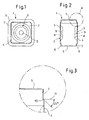
- FIG. 1 shows an inventive cutting plate in plan view, FIG. 2 on average and FIG. 3 the section A of FIG. 2 on an enlarged scale.
- a square cutting plate 1 which is designed as an indexable insert.
- the cutting plate has a top and bottom 2, 3 and a top surface 2 with the bottom 3 connecting side surface 5.
- Adjacent to the cutting edges 6 a circumferential rake face 7 is arranged, which has a depth of 1 mm.
- the side surfaces 5 and the rake face 7 have not undergone any material-removing machining after sintering, so that they have an intact sintered skin.
- a support surface 4 Within the circumferential clamping surface 7 is a support surface 4, with which the cutting plate 1 is seated in a cutting tool.
- the support surface 4 is raised relative to the rake face 7.
- the height difference of the bearing surface 4 to the clamping surface 7 is in the embodiment described here between 0.05 to 0.1 mm.
- the rake face 7 is in the support surface 4 via.
- the slope 10 extends at an angle of 45 degrees to the surface normal 11 of the rake face. 7
- the support surface 4 is provided with a clamping recess 8, wherein the clamping recess 8 is circular and has a spherical or circular elevation 9 in the middle and the elevation 9 is above the trough bottom and below the support surface 4.
- For fastening preferably engages an engagement element of a tool holder with a circular ring in the circular clamping recess and thereby surrounds the elevation.
Landscapes
- Engineering & Computer Science (AREA)
- Chemical & Material Sciences (AREA)
- Ceramic Engineering (AREA)
- Manufacturing & Machinery (AREA)
- Structural Engineering (AREA)
- Materials Engineering (AREA)
- Organic Chemistry (AREA)
- Mechanical Engineering (AREA)
- Composite Materials (AREA)
- Inorganic Chemistry (AREA)
- Cutting Tools, Boring Holders, And Turrets (AREA)
- Ceramic Products (AREA)
- Mounting, Exchange, And Manufacturing Of Dies (AREA)
- Powder Metallurgy (AREA)
Description
- Die Erfindung betrifft eine einsatzbereite durch Sintern eines Rohlings hergestellte keramische Schneidplatte gemäss dem Oberbegriff des Patentanspruchs 1, siehe z.B. die Dokumente
US 4963061 A undDE 200 00738 U1 . - Nach dem Stand der Technik werden die engen Toleranzen für eine keramische Schneidplatte (z. B. bei der G-Toleranz im Inkreisdurchmesser ± 25 µm bei d = 12,7 mm und in der Dicke s = ±130 µm) durch Nachschleifen nach dem Sintern, d. h. in dem Zustand, in dem der Werkstoff bereits alle seine herausragenden Eigenschaften ausgebildet hat, mit Diamantwerkzeugen eingestellt. Neben den Winkeln, Radien und der Schneidkantenpräparation der Wendeschneidplatten kommt es auch auf einen sicheren Halt der Wendeschneidplatte im Plattensitz an. Dieses stellt entsprechende Anforderungen an die Ebenheit der Auflagefläche der Wendeschneidplatten. Diese Anforderung wird durch Planschleifen mit Diamantwerkzeugen erreicht. Dieses Nachbearbeiten ist immer mit hohen Schleifkräften und -drücken verbunden, die Schädigungen des Werkstoffes bewirken.
- Der Erfindung liegt die Aufgabe zugrunde, eine einsatzbereite Schneidplatte nach dem Oberbegriff des Anspruchs 1 so zu verbessern, dass eine Nachbearbeitung nach dem Sintern zumindest teilweise vermieden ist. Außerdem sollen die Vorteile der fertiggepressten / fertiggesinterten Kontaktflächen zwischen der Schneidplatte und dem Werkstück genützt werden. Es soll auch ein optimales Aufliegen der Schneidplatte gewährleistet sein, damit Vibrationen mit den damit verbundenen Mikroausbrüchen/Verschleiß verhindert ist.
- Nachfolgend wird die Erfindung anhand der Ansprüche und der Figuren näher erläutert.
- Dadurch, dass angrenzend an die Schneidkanten eine umlaufende Spanfläche angeordnet ist und die Spanfläche die Auflagefläche umgrenzt, wobei die Seitenflächen, die Schneidkanten und die Spanfläche aus der beim Sintern entstandenen Sinterhaut bestehen und keine Schädigung durch eine materialabtragende Bearbeitung erfahren haben und ausschließlich die Auflageflächen einer materialabtragenden Bearbeitung unterzogen wurden und nicht aus der beim Sintern entstandenen Sinterhaut bestehen ist eine Nachbearbeitung nach dem Sintern für diese Flächen vermieden. Da die Sinterhaut häufig eine höhere Härte als der Grundwerkstoff besitzt, wird die Verschleißfestigkeit des Schneidstoffes bzw. der Schneidplatte dadurch erhöht und die Standzeit verlängert.
- Bevorzugt genügt die Schneidplatte einer Maßhaltigkeit nach M-Toleranz nach IS01382 oder einer Maßhaltigkeit nach G-Toleranz nach IS01382. Durch diese engen Toleranzen ist die Maßhaltigkeit gegeben und sind Fehler durch Abweichung von der Toleranz verhindert.
- Zur Befestigung der Schneidplatte weist die Auflagefläche bevorzugt eine Spannmulde auf. Diese ist bevorzugt kreisförmig ausgebildet und weist in der Mitte eine kugel- bzw. kreisförmige Erhebung auf, wobei die Erhebung oberhalb des Muldenbodens liegt und der höchste Punkt der Erhebung unterhalb der Auflagefläche liegt.
- Bevorzugt besteht die Schneidplatte aus einer oder mehreren der nachfolgend genannten Keramik-Schneidstoffen:
- α-/β-SiAlONe mit und ohne Hartstoffverstärkung
- β-Si3N4 mit und ohne Hartstoffverstärkung
- Mischkeramik (Al2O3 - Ti(C, N))
- ZTA (Al2O3 - ZrO2)
- Die Erfindung betrifft auch ein Verfahren gemäss dem Oberbegriff des Patentanspruchs 6.
- Bevorzugt werden die Auflageflächen vor dem Sintern gegenüber den Spanflächen erhaben ausgebildet, wodurch die Auflageflächen nach dem Sintern geschliffen oder geläppt werden können ohne die Spanfläche und die Schneidkanten zu schädigen. Die materialabtragende Behandlung der Auflagefläche nach dem Sintern hat den Vorteil, dass die Schneidplatte optimal im Halter aufliegen kann und damit Vibrationen mit den damit verbundenen Mikroausbrüchen/Verschleiß verhindert sind.
- Bevorzugt wird die Auflagefläche um kleiner 2 mm, bevorzugt zwischen 0,8 mm bis 1,2 mm gegenüber den Spanflächen erhaben ausgebildet.
- Bevorzugt wird durch das Präzisionspressen des Rohlings eine Spannmulde in die Ober- und/oder Unterseite eingepresst.
- In vorteilhafter Ausgestaltung wird zur Herstellung des Rohlings eine oder mehrere der nachfolgend genannten Keramik-Schneidstoffen verwendet:
- α-/β-SiAlONe mit und ohne Hartstoffverstärkung
- β-Si3N4 mit und ohne Hartstoffverstärkung
- Mischkeramik (Al2O3 - Ti(C, N))
- ZTA (Al2O3 - Zr02)
- Bevorzugt werden die Keramik-Schneidstoffe zu einer pressfähigen Masse gemischt, die eine hohe Rieselfähigheit und dadurch insbesondere ein konstantes Formfüllvermögen aufweist, wobei der die Rieselfähigkeit charakterisierende Schüttwinkel der Masse kleiner gleich 35°, bevorzugt kleiner gleich 30°, besonders bevorzugt kleiner gleich 25° einzustellen ist. Durch die genannte Einstellung der Rieselfähigheit und des damit verbundenen Formfüllvermögens wird die Toleranz eingestellt.
- Vor dem Sintern werden vorteilhaft die Pressgrate des Rohlings entfernt ohne dass die Kanten des Rohlings geschädigt werden.
- Bevorzugt wird das unterschiedliche Press- und Schwindungsverhalten verschiedener Massechargen berücksichtigt, wobei durch Press- und Sinterversuche die Gründichte-Schwindungs-Charakteristik jeder Charge ermittelt und daraus die notwendige Fertigungsgründichte festgelegt wird und diese Fertigungsgründichte beim Einstellen der Pressen als Sollwert für die Gründichte der Rohlinge eingestellt wird. Dies ist ein wichtiger Schritt des erforderlichen Präzisionspressens.
- Bevorzugt wird beim Sintern der Gasaustausch zwischen der Ofenatmosphäre und des Tiegelinneren, in denen die Rohlinge gesintert werden, minimiert und es werden nur Tiegelmaterialien verwendet, die inert sind, d.h. in keinster Weise mit den Rohlingen beim Sintern wechselwirken. Es kommt dadurch zu keinen Verunreinigungen.
- Eine erfindungsgemäße Schneidplatte genügt so bevorzugt einer Maßhaltigkeit nach M-Toleranz nach ISO1382 und/oder einer Maßhaltigkeit nach G-Toleranz nach IS01382.
- Bevorzugt ist die Schneidplatte eine Wendeschneidplatte.
- Bevorzugt wird die erfindungsgemäße Schneidplatte zur Zerspanung von Metallen, NE - Metallen, Kunststoffen, Holz oder Verbundwerkstoffen verwendet.
- Erfindungsgemäß werden beim Herstellen von Wendeschneidplatten aus Werkstoffen der Hochleistungskeramik durch Präzisionspressen und Direktsintern die Maße unter Einhaltung der M- und G-Toleranz nach ISO 1832 erreicht.
- Die erfinderische Tätigkeit besteht unter anderem darin, den Rohling der Schneidplatte, vor dem Sintern, durch präzises Pressen (hier auch Präzisionspressen genannt) in eine derartige Form zu bringen, die es ermöglicht, dass nach dem Sintern an den Seitenflächen, den Schneidkanten und den Spanflächen ein Schleifen oder Läppen der fertig gesinterten Schneidplatte nicht mehr nötig ist.
- Die Erfindung bewirkt folgende Verbesserungen in der Anwendung:
- Die Schädigung der Keramik durch Schleifen oder Läppen erfolgt nur an der Auflagefläche, d.h. geringere Anfälligkeit der Schneidplatten im Einsatz bezüglich Ausschiefern und Ausbröckeln.
- Die "Sinterhaut" bleibt erhalten. Da die Sinterhaut häufig eine höhere Härte als der Grundwerkstoff besitzt, wird die Verschleißfestigkeit des Schneidstoffes nochmals erhöht, welches sich in der Praxis bei der Zerspanung durch geringeren Freiflächen- und Kerbverschleiß äußert.
- Durch den geringeren Gesamtverschleiß an der Wendeschneidplatte können aufgrund der dadurch entstehenden geringeren Schnittkräfte auch Ausbrüche am Bauteil reduziert werden.
- Ein Vorteil ist auch, dass die Spanflächen als Spanbrecher ein Umlenken des Spanes bewirken
- Vorteilhaft ist auch eine Erniedrigung der Geräuschentwicklung beim Einsatz der erfindungsgemäßen Wendeschneidplatte (WSP).
- Die Erfindung beruht auf folgenden erfinderischen Leistungen bzw. folgende Merkmale bei der Herstellung sind alleine oder in Kombination vorteilhaft zu beachten:
- Beim Pressen des Rohlings ist vorteilhaft ein sehr genauer und präzise zentrierter Spalt zwischen Pressstempeln und Matrize einzustellen. Dies kann insbesondere durch ein Schnellspannsystem realisiert werden.
- Der Pressablauf wird bevorzugt extrem genau und mit hoher Reproduzierbarkeit eingestellt.
- Pressfähige Masse mit bevorzugt sehr hoher Rieselfähigkeit und dadurch konstantem Formfüllvermögen. Die Rieselfähigkeit wird durch den sogenannten Schüttwinkel charakterisiert. Für die Messung lässt man eine definierte Menge Pressgranulat in einen durchsichtigen Behälter gleichmäßig einrieseln. Dann wird die Bodenplatte ein Stück weit geöffnet, so dass ein Teil des Pulvers ausläuft. Je nach Rieselfähigkeit des Granulates bildet das im Behälter verbliebene Pulver eine mehr oder weniger steile Kante, deren Winkel als Schüttwinkel gemessen wird. Der Schüttwinkel sollte für eine gute Rieselfähigkeit kleiner gleich 35°, bevorzugt kleiner gleich 30°, besonders bevorzugt kleiner gleich 25° betragen.
- Eine hohe Konstanz in der Gründichte aller Rohlinge ist notwendig. Dies wird erreicht durch eine Masse mit sehr guter Rieselfähigkeit und einer sehr genau regelnden Presse. Mit einer automatischen Masse- und Höhenmessung in Anschluss an die Presse kann die Gründichte von jedem Pressteil berechnet werden. Die Streuung der Gründichte von Rohling zu Rohling sollte kleiner gleich 0,5% bevorzugt kleiner gleich 0,3% vom Mittelwert betragen (Beispiel s.
Figur 1 : Fertigungsgründichte 1,956 g/cm3, Gründichten sind innerhalb 1,951 - 1,963 g/cm3, Soll bei max. 0,3% Abweichung: 1,951 - 1,962 g/cm3). - Entfernen der Pressgrate des Rohlings, ohne dass die Kanten des Rohlings geschädigt werden. Aufgrund des Spaltes zwischen Pressstempeln und Matrize verbleibt auf dem Rohling ein dünner Grat. Dieser muss vor dem Sintern entfernt werden, damit dieser nicht ansintert und später zu Ausbrüchen der Kante führen kann.
- Berücksichtigung des unterschiedlichen Press- und Schwindungsverhaltens verschiedener Massechargen. Hierbei wird durch Press- und Sinterversuche die Gründichte-Schwindungs-Charakteristik jeder Charge ermittelt und daraus die notwendige Fertigungsgründichte festgelegt. Diese Fertigungsgründichte gilt beim Einstellen der Pressen als Sollwert für die Gründichte der Rohlinge.
- Spezieller Ofenaufbau zur Vermeidung von Sinterverzug, Dichte-, Schwindungs- und Farbgradienten. Insbesondere muss der Gasaustausch zwischen Ofenatmosphäre und Tiegelinnerem minimiert werden. Zusätzlich dürfen nur Tiegelmaterialien verwendet werden, die inert sind, d.h. in keinster Weise mit dem Rohlingen beim Sintern wechselwirken. Diese Maßnahmen sind notwendig, um eine homogene Schwindung der Rohlinge während des Sinterns zu erreichen. Finden dagegen Wechselwirkungen der Rohlinge mit der Ofenatmosphäre oder dem Tiegelmaterial statt, wird die Schwindung der Rohlinge lokal beeinflusst, so dass ein Verzug beim Sintern stattfindet und die Maßhaltigkeit nicht mehr gewährleistet werden kann. Wenn ein Sinterverzug auftritt, sind in der Regel vor allem Ecken und Kanten der am Rand gesetzten Teile betroffen. Beispielsweise führt im Falle von Siliziumnitrid- oder SiAlON-Materialien eine hohe Konzentration an Kohlenstoff in der Gasatmosphäre durch z.B. neue Grafitmaterialien des Tiegels oder der Ofenisolation zu einer Reduzierung der zur Verdichtung unbedingt notwendigen Sinteradditive an der Oberfläche. Dadurch ist die Schwindung am Bauteilrand geringer als in der Bauteilmitte, wodurch ein Verzug im gesinterten Bauteil entsteht.
- Zum besseren Einspannen der Schneidplatte ist bevorzugt in den Schneidplatten eine Mulde eingebracht, wie sie in der
WO 03/013770 A1 - Damit immer konstante Einbaubedingungen gegeben sind, ist in einer anderen erfindungsgemäßen Ausführungsform die Mulde so ausgebildet, wie es in der
EP 1 536 903 B1 beschrieben ist. In diesem Fall ist eine erste Spannmulde zum Einspannen in das Schneidwerkzeug eingebracht und ist koaxial zur ersten Spannmulde eine zweite Spannmulde angeordnet, wobei die erste Spannmulde tiefer als die zweite Spannmulde und beide tiefer als die Schneidplattenoberseite angeordnet sind. Beim Klemmen dieser Schneidplatte in einem Werkzeug liegt eine Spannpratze des Werkzeugs auf der zweiten Spannmulde auf und greift zum Beispiel mit einer Nase in die erste Spannmulde ein. Der Abstand von der Auflagefläche der Spannpratze zur Mulde ist damit immer konstant. -
Figur 1 zeigt eine erfindungsgemäße Schneidplatte in Draufsicht,Figur 2 im Schnitt undFigur 3 den Ausschnitt A vonFigur 2 im vergrößerten Maßstab. - Im gezeigten Beispiel handelt es sich um eine quadratische Schneidplatte 1, die als Wendeschneidplatte ausgebildet ist. Die Schneidplatte hat eine Ober- und Unterseite 2, 3 und eine die Oberseite 2 mit der Unterseite 3 verbindende Seitenfläche 5. Angrenzend an die Schneidkanten 6 ist eine umlaufende Spanfläche 7 angeordnet, die eine Tiefe von 1 mm hat. Die Seitenflächen 5 und die Spanfläche 7 sind nach dem Sintern keiner materialabtragenden Bearbeitung unterzogen worden, so dass sie über eine unverletzte Sinterhaut verfügen. Innerhalb der umlaufenden Spanfläche 7 befindet sich eine Auflagefläche 4, mit der die Schneidplatte 1 in einem Schneidwerkzeug aufsitzt. Die Auflagefläche 4 ist gegenüber der Spanfläche 7 erhaben. Der Höhenunterschied der Auflagefläche 4 zur Spanfläche 7 liegt bei der hier beschriebenen Ausführungsform zwischen 0,05 bis 0,1 mm. Über eine Schräge 10 geht die Spanfläche 7 in die Auflagefläche 4 über. Die Schräge 10 verläuft unter einem Winkel von 45 Grad zur Oberflächennormalen 11 der Spanfläche 7.
- Die Auflagefläche 4 ist mit einer Spannmulde 8 versehen, wobei die Spannmulde 8 kreisförmig ausgebildet ist und in der Mitte eine kugel- bzw. kreisförmige Erhebung 9 aufweist und die Erhebung 9 oberhalb des Muldenbodens und unterhalb der Auflagefläche 4 liegt. Zum Befestigen greift bevorzugt ein Eingriffelement eines Werkzeughalters mit einem kreisförmiger Ring in die kreisförmige Spannmulde ein und umgreift dabei die Erhebung 9.
Claims (14)
- Einsatzbereite durch Sintern eines Rohlings hergestellte keramische Schneidplatte (1), als Wendeschneidplatte, mit einer Ober- und Unterseite (2, 3), die jeweils eine Auflagefläche (4) für den Einbau in einen Klemmhalter eines Schneidwerkzeuges aufweisen, mit die Ober- und Unterseite (2, 3) verbindenden Seitenflächen (5) und mit Schneidkanten (6) zur spanenden Bearbeitung von Werkstücken, wobei angrenzend an die Schneidkanten (6) eine umlaufende Spanfläche (7) angeordnet ist und die Spanfläche (7) die Auflagefläche (4) umgrenzt, dadurch gekennzeichnet, dass die Seitenflächen (5), die Schneidkanten (6) und die Spanfläche (7) aus der beim Sintern entstandenen Sinterhaut bestehen und ausschließlich die Auflageflächen (4) einer materialabtragenden Bearbeitung unterzogen wurden und nicht aus der beim Sintern entstandenen Sinterhaut bestehen.
- Schneidplatte nach Anspruch 1, dadurch gekennzeichnet, dass die Schneidplatte (1) einer Maßhaltigkeit nach M-Toleranz nach IS01382 genügt oder die Schneidplatte (1) einer Maßhaltigkeit nach G-Toleranz nach IS01382 genügt.
- Schneidplatte nach Anspruch 1 oder 2, dadurch gekennzeichnet, dass die Auflageflächen (4) eine Spannmulde (8) aufweisen.
- Schneidplatte nach Anspruch 3, dadurch gekennzeichnet, dass die Spannmulden (8) in der Mitte eine kugel- bzw. kreisförmige Erhebung (9) aufweisen und die Erhebung (9) oberhalb des Muldenbodens liegt und der höchste Punkt der Erhebung (9) unterhalb der Auflagefläche (4) liegt.
- Schneidplatte nach einem der Ansprüche 1 bis 4, dadurch gekennzeichnet, dass die Schneidplatte (1) aus einer oder mehreren der nachfolgend genannten Keramik-Schneidstoffen besteht:- α-/β-SiAlONe mit und ohne Hartstoffverstärkung- β-Si3N4 mit und ohne Hartstoffverstärkung- Mischkeramik (Al2O3 - Ti(C,N))- ZTA (Al2O3 - Zr02)
- Verfahren zur Herstellung einer durch Sintern eines Rohlings hergestellten keramischen Schneidplatte (1) mit einer Ober- und Unterseite (2, 3), die jeweils eine Auflagefläche (4) für den Einbau in einen Klemmhalter eines Schneidwerkzeuges aufweisen, mit die Ober- und Unterseite (2, 3) verbindenden Seitenflächen (5) und mit Schneidkanten (6) zur spanenden Bearbeitung von Werkstücken, wobei angrenzend an die Schneidkanten (6) eine umlaufende Spanfläche (7) angeordnet wird und die Spanfläche (7) die Auflagefläche (4) umgrenzt, der Rohling der Schneidplatte (1) vor dem Sintern durch Präzisionspressen in die gewünschte Form gebracht und anschließend der Rohling gesintert wird, zur Herstellung einer Schneidplatte (1) nach einem der Ansprüche 1 bis 5, dadurch gekennzeichnet, dass nach dem Sintern ausschließlich die Auflageflächen (4) einer materialabtragenden Behandlung unterzogen werden.
- Verfahren nach Anspruch 6, dadurch gekennzeichnet, dass die Auflageflächen (4) vor dem Sintern gegenüber den Spanflächen (7) erhaben ausgebildet werden.
- Verfahren nach Anspruch 7, dadurch gekennzeichnet, dass die Auflageflächen (4) um kleiner 2 mm, bevorzugt zwischen 0,8 mm bis 1,2 mm gegenüber den Spanflächen (7) erhaben ausgebildet werden.
- Verfahren nach einem der Ansprüche 6 bis 8, dadurch gekennzeichnet, dass durch das Präzisionspressen des Rohlings eine Spannmulde (8) in die Auflagefläche (4) der Ober- und/oder Unterseite (2, 3) eingepresst wird.
- Verfahren nach einem der Ansprüche 6 bis 9, dadurch gekennzeichnet, dass zur Herstellung des Rohlings eine oder mehrere der nachfolgend genannten Keramik-Schneidstoffen verwendet wird:- o-/β-SiAlONe mit und ohne Hartstoffverstärkung- β-Si3N4 mit und ohne Hartstoffverstärkung- Mischkeramik (Al2O3 - Ti(C,N))- ZTA (Al2O3 - ZrO2)
- Verfahren nach einem der Ansprüche 6 bis 10, dadurch gekennzeichnet, dass die Keramik-Schneidstoffe zu einer pressfähigen Masse gemischt werden, die eine hohe Rieselfähigheit und dadurch insbesondere ein konstantes Formfüllvermögen aufweist, wobei der die Rieselfähigkeit charakterisierende Schüttwinkel der Masse kleiner gleich 35°, bevorzugt kleiner gleich 30°, besonders bevorzugt kleiner gleich 25° einzustellen ist.
- Verfahren nach einem der Ansprüche 6 bis 11, dadurch gekennzeichnet, dass vor dem Sintern die Pressgrate des Rohlings entfernt werden ohne dass die Kanten des Rohlings geschädigt werden.
- Verfahren nach einem der Ansprüche 6 bis 12, dadurch gekennzeichnet, dass das unterschiedliche Press- und Schwindungsverhalten verschiedener Massechargen berücksichtigt wird, wobei durch Press- und Sinterversuche die Gründichte-Schwindungs-Charakteristik jeder Charge ermittelt und daraus die notwendige Fertigungsgründichte festgelegt wird und diese Fertigungsgründichte beim Einstellen der Pressen als Sollwert für die Gründichte der Rohlinge eingestellt wird.
- Verfahren nach einem der Ansprüche 6 bis 13, dadurch gekennzeichnet, dass beim Sintern der Gasaustausch zwischen der Ofenatmosphäre und des Tiegelinneren, in denen die Rohlinge gesintert werden, minimiert wird und nur Tiegelmaterialien verwendet werden, die inert sind, d.h. in keinster Weise mit den Rohlingen beim Sintern wechselwirken.
Priority Applications (1)
| Application Number | Priority Date | Filing Date | Title |
|---|---|---|---|
| PL11790781T PL2646186T3 (pl) | 2010-12-01 | 2011-12-01 | Sprasowana na gotowo / wytłoczona na gotowo płytka skrawająca i sposób jej wytwarzania |
Applications Claiming Priority (2)
| Application Number | Priority Date | Filing Date | Title |
|---|---|---|---|
| DE102010062259 | 2010-12-01 | ||
| PCT/EP2011/071457 WO2012072721A1 (de) | 2010-12-01 | 2011-12-01 | Fertiggepresste / fertiggesinterte schneidplatte und verfahren zu deren herstellung |
Publications (2)
| Publication Number | Publication Date |
|---|---|
| EP2646186A1 EP2646186A1 (de) | 2013-10-09 |
| EP2646186B1 true EP2646186B1 (de) | 2015-10-07 |
Family
ID=45092358
Family Applications (1)
| Application Number | Title | Priority Date | Filing Date |
|---|---|---|---|
| EP11790781.6A Not-in-force EP2646186B1 (de) | 2010-12-01 | 2011-12-01 | Fertiggepresste / fertiggesinterte schneidplatte und verfahren zu deren herstellung |
Country Status (10)
| Country | Link |
|---|---|
| US (1) | US9486857B2 (de) |
| EP (1) | EP2646186B1 (de) |
| JP (1) | JP5897028B2 (de) |
| KR (1) | KR101818642B1 (de) |
| CN (1) | CN103328140B (de) |
| DE (1) | DE102011087507A1 (de) |
| ES (1) | ES2558475T3 (de) |
| IL (1) | IL226569A (de) |
| PL (1) | PL2646186T3 (de) |
| WO (1) | WO2012072721A1 (de) |
Families Citing this family (5)
| Publication number | Priority date | Publication date | Assignee | Title |
|---|---|---|---|---|
| US9486857B2 (en) * | 2010-12-01 | 2016-11-08 | Ceramtec Gmbh | Finish-pressed/final-sintered blanking die and method for producing same |
| DE102015224276A1 (de) * | 2014-12-05 | 2016-06-09 | Ceramtec Gmbh | Schneidplattengeometrie zur Schnittkraftreduzierung beim Stechdrehen und ziehenden Schnitt |
| RS62973B1 (sr) * | 2015-01-09 | 2022-03-31 | Ceram Gmbh | Noseći alat |
| DE102015107585A1 (de) | 2015-05-13 | 2016-11-17 | LMT Kieninger GmbH | Schneidplatte, Verfahren zum Herstellen einer Schneidplatte und Schneidwerkzeug |
| JP7065837B6 (ja) | 2016-10-03 | 2022-06-06 | コーニンクレッカ フィリップス エヌ ヴェ | 心腔内心エコー検査用インターポーザ |
Family Cites Families (17)
| Publication number | Priority date | Publication date | Assignee | Title |
|---|---|---|---|---|
| US5024976A (en) * | 1988-11-03 | 1991-06-18 | Kennametal Inc. | Alumina-zirconia-silicon carbide-magnesia ceramic cutting tools |
| US4963061A (en) * | 1989-04-07 | 1990-10-16 | Gte Valenite Corporation | Ceramic cutting insert |
| US5141367A (en) * | 1990-12-18 | 1992-08-25 | Kennametal, Inc. | Ceramic cutting tool with chip control |
| DE69207613T2 (de) * | 1991-02-15 | 1996-09-19 | Sumitomo Electric Industries | Werkzeug aus gesintertem Siliciumnitrid |
| US5116167A (en) * | 1991-02-19 | 1992-05-26 | Kennametal Inc. | Cutting insert with chip control |
| US5122017A (en) * | 1991-02-19 | 1992-06-16 | Kennametal Inc. | Cutting insert with chip control |
| DE20000738U1 (de) | 2000-01-18 | 2000-03-30 | Jongen Werkzeugtechnik GmbH & Co. KG, 47877 Willich | Schneidplatte, insbesondere Wendeschneidplatte |
| DE10208266A1 (de) | 2001-07-26 | 2003-02-13 | Ceram Tec Ag Innovative Cerami | Spanabhebendes Schneidwerkzeug und Schneidplatte in Donut-Form |
| US7073986B2 (en) | 2001-11-08 | 2006-07-11 | Kennametal Inc. | Dimpled insert with retaining clamp |
| DE10239451A1 (de) | 2002-08-28 | 2004-03-11 | Ceramtec Ag Innovative Ceramic Engineering | Schneidplatte mit Doppelmulde |
| US20090035521A1 (en) | 2003-08-22 | 2009-02-05 | Andreas Hafner | Die consisting of PCBN or a CBN composite material comprising a clamping depression |
| JP2005126304A (ja) * | 2003-10-27 | 2005-05-19 | Ngk Spark Plug Co Ltd | 工具用部材及び工具 |
| SE529421C2 (sv) * | 2005-12-27 | 2007-08-07 | Sandvik Intellectual Property | Keramikskär med oslipad konkav mellanyta på fasytan samt förfarande för framställning av sådana skär |
| CN101288910A (zh) * | 2008-06-04 | 2008-10-22 | 上海美恩精密工具有限公司 | 一种超硬材料w形刀片可转位刀具 |
| JP2010105134A (ja) * | 2008-10-31 | 2010-05-13 | Sumitomo Electric Hardmetal Corp | 刃先交換式チップとそのチップの加工方法 |
| JP5482602B2 (ja) * | 2010-09-22 | 2014-05-07 | 三菱マテリアル株式会社 | 炭化タングステン基超硬合金製切削インサートおよびその製造方法 |
| US9486857B2 (en) * | 2010-12-01 | 2016-11-08 | Ceramtec Gmbh | Finish-pressed/final-sintered blanking die and method for producing same |
-
2011
- 2011-12-01 US US13/990,086 patent/US9486857B2/en not_active Expired - Fee Related
- 2011-12-01 WO PCT/EP2011/071457 patent/WO2012072721A1/de not_active Ceased
- 2011-12-01 EP EP11790781.6A patent/EP2646186B1/de not_active Not-in-force
- 2011-12-01 DE DE102011087507A patent/DE102011087507A1/de not_active Withdrawn
- 2011-12-01 CN CN201180066464.7A patent/CN103328140B/zh not_active Expired - Fee Related
- 2011-12-01 ES ES11790781.6T patent/ES2558475T3/es active Active
- 2011-12-01 PL PL11790781T patent/PL2646186T3/pl unknown
- 2011-12-01 JP JP2013541342A patent/JP5897028B2/ja not_active Expired - Fee Related
- 2011-12-01 KR KR1020137017227A patent/KR101818642B1/ko not_active Expired - Fee Related
-
2013
- 2013-05-26 IL IL226569A patent/IL226569A/en not_active IP Right Cessation
Also Published As
| Publication number | Publication date |
|---|---|
| IL226569A (en) | 2017-02-28 |
| US20130251467A1 (en) | 2013-09-26 |
| KR101818642B1 (ko) | 2018-01-15 |
| DE102011087507A1 (de) | 2012-06-06 |
| ES2558475T3 (es) | 2016-02-04 |
| KR20130122765A (ko) | 2013-11-08 |
| JP2014501628A (ja) | 2014-01-23 |
| CN103328140A (zh) | 2013-09-25 |
| EP2646186A1 (de) | 2013-10-09 |
| US9486857B2 (en) | 2016-11-08 |
| PL2646186T3 (pl) | 2016-06-30 |
| WO2012072721A1 (de) | 2012-06-07 |
| JP5897028B2 (ja) | 2016-03-30 |
| CN103328140B (zh) | 2015-12-16 |
Similar Documents
| Publication | Publication Date | Title |
|---|---|---|
| EP3107676B1 (de) | Indexierbarer schneideinsatz und fräswerkzeug | |
| AT505947B1 (de) | Verdichtungswerkzeug | |
| EP2162255A1 (de) | Negative schneidplatte mit doppelt-positiver freifläche | |
| CH631371A5 (de) | Verfahren zur bearbeitung eines teils aus polykristallinem, synthetischem diamant mit metallischem binder. | |
| EP2646186A1 (de) | Fertiggepresste / fertiggesinterte schneidplatte und verfahren zu deren herstellung | |
| EP3525970A1 (de) | Verfahren und vorrichtung zur herstellung eines hartmetallpresslings sowie hartmetallpressling | |
| DE2011082A1 (de) | Schneidwerkzeug | |
| EP3439815B1 (de) | Verfahren und vorrichtung zur herstellung eines hartmetallpresslings | |
| DE112015005556T5 (de) | Verfahren zur Herstellung einer Sinterkomponente, Sinterkomponente und Bohrer | |
| DE69203962T2 (de) | Verfahren zur herstellung eines harten sinterkörpers. | |
| DE112020002102T5 (de) | Verfahren zur Herstellung von Sinterkörpern und Pulverpresslingen | |
| DE112020003057B4 (de) | Einsatz und Schneidwerkzeug | |
| EP2467226A1 (de) | Präzisionspressen und sintern von schneidplatten, insbesondere wendeschneidplatten | |
| EP3885071A1 (de) | Vorrichtung und verfahren zum spannen von werkstücken | |
| DE19533836B4 (de) | Profilschleifscheibe und Verfahren und Vorrichtung zur Herstellung | |
| DE60020009T2 (de) | Schneidwerkzeug | |
| DE112021005524T5 (de) | Verfahren zur Herstellung eines Sinterzahnrads | |
| DE102013107629A1 (de) | Schneideinsatz, Schneidwerkzeug und Verfahren zur Schneidenjustierung | |
| WO2019025229A1 (de) | Verfahren zur herstellung eines bearbeitungssegmentes für ein abrasives bearbeitungswerkzeug | |
| DE3810032A1 (de) | Wendeschneidplatte und vorrichtung sowie verfahren fuer ihre herstellung | |
| DE112010000928B4 (de) | Schleifwerkzeug | |
| CH669357A5 (de) | ||
| DE20000738U1 (de) | Schneidplatte, insbesondere Wendeschneidplatte | |
| DE102016209990B3 (de) | Hüftgelenkimplantat | |
| WO1987001634A1 (fr) | Procede et dispositif de frittage sous pression pour la production d'outils diamants noyes dans du metal |
Legal Events
| Date | Code | Title | Description |
|---|---|---|---|
| PUAI | Public reference made under article 153(3) epc to a published international application that has entered the european phase |
Free format text: ORIGINAL CODE: 0009012 |
|
| 17P | Request for examination filed |
Effective date: 20130701 |
|
| AK | Designated contracting states |
Kind code of ref document: A1 Designated state(s): AL AT BE BG CH CY CZ DE DK EE ES FI FR GB GR HR HU IE IS IT LI LT LU LV MC MK MT NL NO PL PT RO RS SE SI SK SM TR |
|
| DAX | Request for extension of the european patent (deleted) | ||
| GRAP | Despatch of communication of intention to grant a patent |
Free format text: ORIGINAL CODE: EPIDOSNIGR1 |
|
| RIC1 | Information provided on ipc code assigned before grant |
Ipc: B23B 27/14 20060101AFI20150318BHEP Ipc: C04B 35/119 20060101ALI20150318BHEP Ipc: C04B 35/597 20060101ALI20150318BHEP Ipc: C04B 35/117 20060101ALI20150318BHEP Ipc: C04B 35/64 20060101ALI20150318BHEP Ipc: B23P 15/28 20060101ALI20150318BHEP Ipc: C04B 35/584 20060101ALI20150318BHEP |
|
| INTG | Intention to grant announced |
Effective date: 20150417 |
|
| GRAS | Grant fee paid |
Free format text: ORIGINAL CODE: EPIDOSNIGR3 |
|
| GRAA | (expected) grant |
Free format text: ORIGINAL CODE: 0009210 |
|
| AK | Designated contracting states |
Kind code of ref document: B1 Designated state(s): AL AT BE BG CH CY CZ DE DK EE ES FI FR GB GR HR HU IE IS IT LI LT LU LV MC MK MT NL NO PL PT RO RS SE SI SK SM TR |
|
| REG | Reference to a national code |
Ref country code: GB Ref legal event code: FG4D Free format text: NOT ENGLISH |
|
| REG | Reference to a national code |
Ref country code: AT Ref legal event code: REF Ref document number: 753432 Country of ref document: AT Kind code of ref document: T Effective date: 20151015 Ref country code: CH Ref legal event code: EP |
|
| REG | Reference to a national code |
Ref country code: IE Ref legal event code: FG4D Free format text: LANGUAGE OF EP DOCUMENT: GERMAN |
|
| REG | Reference to a national code |
Ref country code: DE Ref legal event code: R096 Ref document number: 502011008033 Country of ref document: DE |
|
| REG | Reference to a national code |
Ref country code: FR Ref legal event code: PLFP Year of fee payment: 5 |
|
| REG | Reference to a national code |
Ref country code: SE Ref legal event code: TRGR |
|
| REG | Reference to a national code |
Ref country code: ES Ref legal event code: FG2A Ref document number: 2558475 Country of ref document: ES Kind code of ref document: T3 Effective date: 20160204 |
|
| REG | Reference to a national code |
Ref country code: NL Ref legal event code: MP Effective date: 20151007 |
|
| REG | Reference to a national code |
Ref country code: LT Ref legal event code: MG4D |
|
| PG25 | Lapsed in a contracting state [announced via postgrant information from national office to epo] |
Ref country code: LT Free format text: LAPSE BECAUSE OF FAILURE TO SUBMIT A TRANSLATION OF THE DESCRIPTION OR TO PAY THE FEE WITHIN THE PRESCRIBED TIME-LIMIT Effective date: 20151007 Ref country code: IS Free format text: LAPSE BECAUSE OF FAILURE TO SUBMIT A TRANSLATION OF THE DESCRIPTION OR TO PAY THE FEE WITHIN THE PRESCRIBED TIME-LIMIT Effective date: 20160207 Ref country code: NO Free format text: LAPSE BECAUSE OF FAILURE TO SUBMIT A TRANSLATION OF THE DESCRIPTION OR TO PAY THE FEE WITHIN THE PRESCRIBED TIME-LIMIT Effective date: 20160107 Ref country code: HR Free format text: LAPSE BECAUSE OF FAILURE TO SUBMIT A TRANSLATION OF THE DESCRIPTION OR TO PAY THE FEE WITHIN THE PRESCRIBED TIME-LIMIT Effective date: 20151007 Ref country code: NL Free format text: LAPSE BECAUSE OF FAILURE TO SUBMIT A TRANSLATION OF THE DESCRIPTION OR TO PAY THE FEE WITHIN THE PRESCRIBED TIME-LIMIT Effective date: 20151007 |
|
| PG25 | Lapsed in a contracting state [announced via postgrant information from national office to epo] |
Ref country code: FI Free format text: LAPSE BECAUSE OF FAILURE TO SUBMIT A TRANSLATION OF THE DESCRIPTION OR TO PAY THE FEE WITHIN THE PRESCRIBED TIME-LIMIT Effective date: 20151007 Ref country code: BE Free format text: LAPSE BECAUSE OF NON-PAYMENT OF DUE FEES Effective date: 20151231 Ref country code: LV Free format text: LAPSE BECAUSE OF FAILURE TO SUBMIT A TRANSLATION OF THE DESCRIPTION OR TO PAY THE FEE WITHIN THE PRESCRIBED TIME-LIMIT Effective date: 20151007 Ref country code: RS Free format text: LAPSE BECAUSE OF FAILURE TO SUBMIT A TRANSLATION OF THE DESCRIPTION OR TO PAY THE FEE WITHIN THE PRESCRIBED TIME-LIMIT Effective date: 20151007 Ref country code: PT Free format text: LAPSE BECAUSE OF FAILURE TO SUBMIT A TRANSLATION OF THE DESCRIPTION OR TO PAY THE FEE WITHIN THE PRESCRIBED TIME-LIMIT Effective date: 20160208 Ref country code: GR Free format text: LAPSE BECAUSE OF FAILURE TO SUBMIT A TRANSLATION OF THE DESCRIPTION OR TO PAY THE FEE WITHIN THE PRESCRIBED TIME-LIMIT Effective date: 20160108 |
|
| REG | Reference to a national code |
Ref country code: DE Ref legal event code: R097 Ref document number: 502011008033 Country of ref document: DE |
|
| PG25 | Lapsed in a contracting state [announced via postgrant information from national office to epo] |
Ref country code: CZ Free format text: LAPSE BECAUSE OF FAILURE TO SUBMIT A TRANSLATION OF THE DESCRIPTION OR TO PAY THE FEE WITHIN THE PRESCRIBED TIME-LIMIT Effective date: 20151007 Ref country code: LU Free format text: LAPSE BECAUSE OF FAILURE TO SUBMIT A TRANSLATION OF THE DESCRIPTION OR TO PAY THE FEE WITHIN THE PRESCRIBED TIME-LIMIT Effective date: 20151201 Ref country code: MC Free format text: LAPSE BECAUSE OF FAILURE TO SUBMIT A TRANSLATION OF THE DESCRIPTION OR TO PAY THE FEE WITHIN THE PRESCRIBED TIME-LIMIT Effective date: 20151007 |
|
| REG | Reference to a national code |
Ref country code: CH Ref legal event code: PL |
|
| PLBE | No opposition filed within time limit |
Free format text: ORIGINAL CODE: 0009261 |
|
| STAA | Information on the status of an ep patent application or granted ep patent |
Free format text: STATUS: NO OPPOSITION FILED WITHIN TIME LIMIT |
|
| PG25 | Lapsed in a contracting state [announced via postgrant information from national office to epo] |
Ref country code: EE Free format text: LAPSE BECAUSE OF FAILURE TO SUBMIT A TRANSLATION OF THE DESCRIPTION OR TO PAY THE FEE WITHIN THE PRESCRIBED TIME-LIMIT Effective date: 20151007 Ref country code: SM Free format text: LAPSE BECAUSE OF FAILURE TO SUBMIT A TRANSLATION OF THE DESCRIPTION OR TO PAY THE FEE WITHIN THE PRESCRIBED TIME-LIMIT Effective date: 20151007 Ref country code: SK Free format text: LAPSE BECAUSE OF FAILURE TO SUBMIT A TRANSLATION OF THE DESCRIPTION OR TO PAY THE FEE WITHIN THE PRESCRIBED TIME-LIMIT Effective date: 20151007 Ref country code: RO Free format text: LAPSE BECAUSE OF FAILURE TO SUBMIT A TRANSLATION OF THE DESCRIPTION OR TO PAY THE FEE WITHIN THE PRESCRIBED TIME-LIMIT Effective date: 20151007 Ref country code: DK Free format text: LAPSE BECAUSE OF FAILURE TO SUBMIT A TRANSLATION OF THE DESCRIPTION OR TO PAY THE FEE WITHIN THE PRESCRIBED TIME-LIMIT Effective date: 20151007 |
|
| 26N | No opposition filed |
Effective date: 20160708 |
|
| REG | Reference to a national code |
Ref country code: IE Ref legal event code: MM4A |
|
| PG25 | Lapsed in a contracting state [announced via postgrant information from national office to epo] |
Ref country code: IE Free format text: LAPSE BECAUSE OF NON-PAYMENT OF DUE FEES Effective date: 20151201 Ref country code: CH Free format text: LAPSE BECAUSE OF NON-PAYMENT OF DUE FEES Effective date: 20151231 Ref country code: LI Free format text: LAPSE BECAUSE OF NON-PAYMENT OF DUE FEES Effective date: 20151231 |
|
| PG25 | Lapsed in a contracting state [announced via postgrant information from national office to epo] |
Ref country code: SI Free format text: LAPSE BECAUSE OF FAILURE TO SUBMIT A TRANSLATION OF THE DESCRIPTION OR TO PAY THE FEE WITHIN THE PRESCRIBED TIME-LIMIT Effective date: 20151007 |
|
| REG | Reference to a national code |
Ref country code: FR Ref legal event code: PLFP Year of fee payment: 6 |
|
| PG25 | Lapsed in a contracting state [announced via postgrant information from national office to epo] |
Ref country code: HU Free format text: LAPSE BECAUSE OF FAILURE TO SUBMIT A TRANSLATION OF THE DESCRIPTION OR TO PAY THE FEE WITHIN THE PRESCRIBED TIME-LIMIT; INVALID AB INITIO Effective date: 20111201 Ref country code: BG Free format text: LAPSE BECAUSE OF FAILURE TO SUBMIT A TRANSLATION OF THE DESCRIPTION OR TO PAY THE FEE WITHIN THE PRESCRIBED TIME-LIMIT Effective date: 20151007 |
|
| PG25 | Lapsed in a contracting state [announced via postgrant information from national office to epo] |
Ref country code: CY Free format text: LAPSE BECAUSE OF FAILURE TO SUBMIT A TRANSLATION OF THE DESCRIPTION OR TO PAY THE FEE WITHIN THE PRESCRIBED TIME-LIMIT Effective date: 20151007 |
|
| PG25 | Lapsed in a contracting state [announced via postgrant information from national office to epo] |
Ref country code: MT Free format text: LAPSE BECAUSE OF FAILURE TO SUBMIT A TRANSLATION OF THE DESCRIPTION OR TO PAY THE FEE WITHIN THE PRESCRIBED TIME-LIMIT Effective date: 20151007 |
|
| REG | Reference to a national code |
Ref country code: FR Ref legal event code: PLFP Year of fee payment: 7 |
|
| PGFP | Annual fee paid to national office [announced via postgrant information from national office to epo] |
Ref country code: TR Payment date: 20171130 Year of fee payment: 7 Ref country code: FR Payment date: 20171221 Year of fee payment: 7 |
|
| REG | Reference to a national code |
Ref country code: AT Ref legal event code: MM01 Ref document number: 753432 Country of ref document: AT Kind code of ref document: T Effective date: 20161201 |
|
| PGFP | Annual fee paid to national office [announced via postgrant information from national office to epo] |
Ref country code: GB Payment date: 20171221 Year of fee payment: 7 Ref country code: SE Payment date: 20171219 Year of fee payment: 7 Ref country code: PL Payment date: 20171123 Year of fee payment: 7 |
|
| PGFP | Annual fee paid to national office [announced via postgrant information from national office to epo] |
Ref country code: DE Payment date: 20180228 Year of fee payment: 7 Ref country code: ES Payment date: 20180124 Year of fee payment: 7 |
|
| PG25 | Lapsed in a contracting state [announced via postgrant information from national office to epo] |
Ref country code: AT Free format text: LAPSE BECAUSE OF NON-PAYMENT OF DUE FEES Effective date: 20161201 |
|
| PGFP | Annual fee paid to national office [announced via postgrant information from national office to epo] |
Ref country code: IT Payment date: 20171221 Year of fee payment: 7 |
|
| PG25 | Lapsed in a contracting state [announced via postgrant information from national office to epo] |
Ref country code: MK Free format text: LAPSE BECAUSE OF FAILURE TO SUBMIT A TRANSLATION OF THE DESCRIPTION OR TO PAY THE FEE WITHIN THE PRESCRIBED TIME-LIMIT Effective date: 20151007 |
|
| PG25 | Lapsed in a contracting state [announced via postgrant information from national office to epo] |
Ref country code: AL Free format text: LAPSE BECAUSE OF FAILURE TO SUBMIT A TRANSLATION OF THE DESCRIPTION OR TO PAY THE FEE WITHIN THE PRESCRIBED TIME-LIMIT Effective date: 20151007 |
|
| REG | Reference to a national code |
Ref country code: DE Ref legal event code: R119 Ref document number: 502011008033 Country of ref document: DE |
|
| REG | Reference to a national code |
Ref country code: SE Ref legal event code: EUG |
|
| PG25 | Lapsed in a contracting state [announced via postgrant information from national office to epo] |
Ref country code: SE Free format text: LAPSE BECAUSE OF NON-PAYMENT OF DUE FEES Effective date: 20181202 |
|
| GBPC | Gb: european patent ceased through non-payment of renewal fee |
Effective date: 20181201 |
|
| PG25 | Lapsed in a contracting state [announced via postgrant information from national office to epo] |
Ref country code: IT Free format text: LAPSE BECAUSE OF NON-PAYMENT OF DUE FEES Effective date: 20181201 Ref country code: FR Free format text: LAPSE BECAUSE OF NON-PAYMENT OF DUE FEES Effective date: 20181231 Ref country code: DE Free format text: LAPSE BECAUSE OF NON-PAYMENT OF DUE FEES Effective date: 20190702 |
|
| PG25 | Lapsed in a contracting state [announced via postgrant information from national office to epo] |
Ref country code: GB Free format text: LAPSE BECAUSE OF NON-PAYMENT OF DUE FEES Effective date: 20181201 |
|
| REG | Reference to a national code |
Ref country code: ES Ref legal event code: FD2A Effective date: 20200131 |
|
| PG25 | Lapsed in a contracting state [announced via postgrant information from national office to epo] |
Ref country code: ES Free format text: LAPSE BECAUSE OF NON-PAYMENT OF DUE FEES Effective date: 20181202 |
|
| PG25 | Lapsed in a contracting state [announced via postgrant information from national office to epo] |
Ref country code: PL Free format text: LAPSE BECAUSE OF NON-PAYMENT OF DUE FEES Effective date: 20181201 |
|
| PG25 | Lapsed in a contracting state [announced via postgrant information from national office to epo] |
Ref country code: TR Free format text: LAPSE BECAUSE OF NON-PAYMENT OF DUE FEES Effective date: 20181201 |