EP2645944B1 - Vorrichtung zum verlängern einer sehne - Google Patents
Vorrichtung zum verlängern einer sehne Download PDFInfo
- Publication number
- EP2645944B1 EP2645944B1 EP11808401.1A EP11808401A EP2645944B1 EP 2645944 B1 EP2645944 B1 EP 2645944B1 EP 11808401 A EP11808401 A EP 11808401A EP 2645944 B1 EP2645944 B1 EP 2645944B1
- Authority
- EP
- European Patent Office
- Prior art keywords
- shaft
- tendon
- longitudinal axis
- helical
- cutting
- Prior art date
- Legal status (The legal status is an assumption and is not a legal conclusion. Google has not performed a legal analysis and makes no representation as to the accuracy of the status listed.)
- Not-in-force
Links
- 210000002435 tendon Anatomy 0.000 title claims description 90
- 238000000034 method Methods 0.000 description 5
- 238000005266 casting Methods 0.000 description 2
- 238000007796 conventional method Methods 0.000 description 2
- 238000001746 injection moulding Methods 0.000 description 2
- 238000003754 machining Methods 0.000 description 2
- 239000000463 material Substances 0.000 description 2
- 238000002844 melting Methods 0.000 description 2
- 230000008018 melting Effects 0.000 description 2
- 239000002184 metal Substances 0.000 description 2
- 238000000465 moulding Methods 0.000 description 2
- 230000000295 complement effect Effects 0.000 description 1
- 238000010276 construction Methods 0.000 description 1
- 238000002474 experimental method Methods 0.000 description 1
- 230000000149 penetrating effect Effects 0.000 description 1
- 210000004872 soft tissue Anatomy 0.000 description 1
- 210000001519 tissue Anatomy 0.000 description 1
Images




Classifications
-
- A—HUMAN NECESSITIES
- A61—MEDICAL OR VETERINARY SCIENCE; HYGIENE
- A61B—DIAGNOSIS; SURGERY; IDENTIFICATION
- A61B17/00—Surgical instruments, devices or methods
- A61B17/32—Surgical cutting instruments
- A61B17/3209—Incision instruments
-
- A—HUMAN NECESSITIES
- A61—MEDICAL OR VETERINARY SCIENCE; HYGIENE
- A61B—DIAGNOSIS; SURGERY; IDENTIFICATION
- A61B17/00—Surgical instruments, devices or methods
- A61B17/32—Surgical cutting instruments
- A61B17/320016—Endoscopic cutting instruments, e.g. arthroscopes, resectoscopes
-
- A—HUMAN NECESSITIES
- A61—MEDICAL OR VETERINARY SCIENCE; HYGIENE
- A61B—DIAGNOSIS; SURGERY; IDENTIFICATION
- A61B17/00—Surgical instruments, devices or methods
- A61B17/32—Surgical cutting instruments
- A61B2017/320052—Guides for cutting instruments
-
- A—HUMAN NECESSITIES
- A61—MEDICAL OR VETERINARY SCIENCE; HYGIENE
- A61B—DIAGNOSIS; SURGERY; IDENTIFICATION
- A61B90/00—Instruments, implements or accessories specially adapted for surgery or diagnosis and not covered by any of the groups A61B1/00 - A61B50/00, e.g. for luxation treatment or for protecting wound edges
- A61B90/03—Automatic limiting or abutting means, e.g. for safety
- A61B2090/033—Abutting means, stops, e.g. abutting on tissue or skin
- A61B2090/036—Abutting means, stops, e.g. abutting on tissue or skin abutting on tissue or skin
Definitions
- the concepts disclosed herein generally relate to an apparatus and method for cutting a tendon in order to achieve a lengthening thereof without a continuous cut through the tendon. More particularly, the inventive concepts relate to an apparatus which allows a helical or spiral cutting of a tendon. The concepts disclosed herein also relate to a method for lengthening a tendon by helical or spiral cutting.
- EP 1 836 971 A2 discloses a surgical fastener including a filament formed into a generally helical shape around a fastener axis and having a plurality of coils. The proximal end of the filament has an engagement member and the distal end of the filament has a penetrating tip.
- US 2008/045989 A1 discloses an endoscopic tool which includes a two edged blade which can be moved in both the distal to proximal direction and the proximal to distal direction.
- US 2007/288043 A1 discloses an instrument which includes a cannula and a cutting member movable longitudinally within the cannula to advance a cutting blade of the cutting member along a longitudinal slot in the cannula.
- inventive concepts disclosed herein are not limited in its application to the details of construction, experiments, exemplary data, and the arrangement of the components set forth in the following description or illustrated in the drawings.
- inventive concepts are capable of other embodiments or being practiced or carried out in various ways.
- phraseology and terminology employed herein is for purposes of description and should not be regarded as limiting.
- the apparatus 10 includes a cutting blade 13 and a cutting guide 14 for guiding the cutting blade 13 along the tendon in a helical path.
- the cutting guide 14 comprises a shaft 15 with a diameter d, a longitudinal axis 16, a front end 18, and a rear end 20.
- the shaft 15 is provided with a groove 22 near the front end 18 of the shaft 15.
- the groove 22 is formed so that cutting blade 13 is supported at the front end 18 of the shaft 15 so as to protrude unilaterally from the shaft 15.
- the cutting blade 13 has a cutting edge 24 extending from a front face 26 at the front end 18 of the shaft 15.
- the cutting edge 24 increases its distance to the longitudinal axis 16 in a direction towards the rear end 20 of the shaft 15.
- the blade 13 has a middle plane 28 ( FIG. 4 ) which forms an angle ⁇ of exemplarily 45° with the longitudinal axis 16 of the shaft 15.
- the angle ⁇ may be in a range from about 20° to about 70°.
- the groove 22 has a central axis 29 extending along the length of the groove 22.
- the groove 22 is arranged in such a way that the central axis 29 of the groove 22 and the longitudinal axis 16 of the shaft 15 are skew lines. Further, the central axis 29 of the groove 22 forms the identical angle ⁇ with the longitudinal axis 16 of the shaft 15 as the middle plane 28 of the blade 13 ( FIG. 4 ).
- the blade 13 may be symmetrical in a cross-section along line 5-5 in FIG. 4 so that the cutting edge 24 lies in the middle plane 28 of the blade 13.
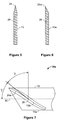
- a blade 13a can be asymmetrical in a cross-section so that the cutting edge 24a lies in a plane which is parallel to the middle plane of the blade 13a and which coincides with one lateral surface of the blade 13.
- the cutting edge 24 of the blade 13 extends to a height H from the longitudinal axis 16 measured orthogonal to the longitudinal axis 16 of the shaft 15 and to a length L measured in the middle plane 28 orthogonal41o the height H.
- the height H is dimensioned to cut a tendon 12 with a diameter of about 2 x H.
- the cutting edge 24 curvedly extends from the shaft 15 on a plane curve which defines a plane coinciding with the middle plane 28 of the blade 13.
- the maximum ratio of L/H is about .70
- the shaft 15 is provided with a cannula 30 ( FIGS. 2A and 3 ) so that the shaft 15 can be slid over and rotated about a K-wire 32 ( FIG. 8 ) which is positioned in the tendon 12 ( FIG. 9 ).
- the shaft 15 also includes an axial extension 38 extending from the rear end 20 of the shaft 15.
- the axial extension 38 is provided with a first helical engagement member 40 extending along the longitudinal axis 16 of the shaft 15.
- the axial extension 38 has a diameter D which is larger than the diameter d of the shaft 15 and has a handle 42 at its rearmost portion.
- the first helical engagement member 40 is configured as a helical ridge having a helix angle with respect to a plane orthogonal to the longitudinal axis 16 of the shaft 15 ( FIG. 1 ) wherein the helix angle corresponds to the angle ⁇ between the middle plane 28 of the blade 13 and the longitudinal axis 16 of the shaft 15.
- the cutting guide 14 further comprises a sleeve 44 with a central opening 46 for receiving the axial extension 38 of the shaft 15.
- the sleeve 44 is provided with a second helical engagement member 48 ( FIG. 2A ) which is engageable with the first helical engagement member 40 of the axial extension 38.
- the second engagement member 48 is configured as a helical groove in the inner wall of the sleeve 44. Thereby, the first and second helical engagement members 40, 48 mate with each other allowing the shaft 15 to move axially relative to the sleeve 44 upon a relative rotation.
- FIG. 7 illustrates an alternative embodiment of an instrument 10a which differs from the embodiment of FIGS. 1-5 as described below.
- a blade 13b is incorporated as part of a cutting guide 14a.
- the blade 13b is a helically twisted band with a helix angle ⁇ between the middle plane 28 of the blade 13b and a plane orthogonal to the longitudinal axis 16 of the shaft 15 wherein the angle ⁇ is complementary to the angle ⁇ between the middle plane 28 of the blade 13b and the longitudinal axis 16 of the shaft 15.
- the middle plane 28 is a helically twisted plane.
- the blade 13b has a cutting edge 13a extending in the helically twisted middle plane 28 of the blade 13b and has a distance to the longitudinal axis 16 of the shaft 15 which continuously increases from the foremost point of the cutting edge 24b at the front end 18 of the shaft 15 to the rearmost point of the cutting edge 24b.
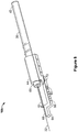
- FIGS. 8 and 9 illustrate another embodiment of an apparatus 10b which differs from the embodiments of FIGS. 1-5 and 7 as described below. More specifically, the apparatus 10b further comprises an adapter 50 which is attached to the sleeve 44.
- the adapter 50 is configured to support the tendon 12 in a bent condition along a section 54 adjacent to a fixed end 56 of the tendon 12 in an S-shaped form so that a longitudinal section 58 of the tendon 12 is shifted with respect to the fixed end 56 of the tendon 12.
- the adapter 50 is an elongated member extending along the longitudinal axis 16 of the shaft 15 and protruding distally from the sleeve 44 so as to form an extension arm 60 providing a first support surface and a second support surface longitudinally and laterally spaced from one another to which a section 54 of the tendon 12 which is adjacent the fixed end 56 of the tendon 12 can be affixed.
- the adapter 50 is stepped away from the longitudinal axis 16 of the shaft 15, so that the adapter 50 can be fixed to the section 54 of the tendon 12 which is adjacent to the fixed end 56 of the tendon 12 in such a way that the axial extension 38 of the shaft 15 can be lead beside the fixed end 56 of the tendon 12 and towards the longitudinal section 58 of the tendon 12 to be treated.
- the adapter 50 has a nose 64 located at the free end of the adapter 50.
- the nose 64 has a contact surface 68 which is spaced apart from the longitudinal axis 16 of the shaft 15 about half of the diameter of the tendon 12, so that the longitudinal section 58 of the tendon 12 that abuts the contact surface 68 comes at rest essentially coaxial to the longitudinal axis 16 of the shaft 15.
- the apparatus 10b is fixed to the tendon 12 by means of a fastener, such as a suture 70, in the proximity of the fixed end 56 of the tendon 12.
- the suture 70 is lead around the tendon 12 and fixed in two notches 72 which are located on opposite lateral sides of the adapter 50.
- the adapter 50 is fixable to the sleeve 44 by means of two fasteners, such as screws.
- FIG. 10 illustrates another embodiment of an apparatus 10c which differs from the embodiment of FIG. 8 , as described below.
- the apparatus 10c has an adapter 50a which comprises an extension arm 60a which protrudes distally from the sleeve 44 and which extends along the longitudinal axis 16 of the shaft 15.
- the adapter 50a comprises two pins 78 that are spaced apart from each other in a direction along the longitudinal axis 16 of the shaft 15.
- the pins 78 are differently spaced apart from the longitudinal axis 16 in a direction orthogonal to the longitudinal axis 16 of the shaft 15.
- the pins 78 can be positioned on opposite sides of the tendon 12 and the shaft 15 including the extension arm 60a can be twisted in such a way that the longitudinal section 58 of the tendon 12 comes at rest essentially coaxial to the longitudinal axis 16 of the shaft 15. Thereby, a section 54 of the tendon 12 which is located between the fixed end 56 of the tendon 12 and the longitudinal section 58 of the tendon 12 to be shifted is positioned between the two pins 78 and bent in a S-shaped form.
- the tendon 12 is bent on a section 54 adjacent to one of the fixed ends 56 of the tendon 12 in such a way that a longitudinal section 58 of the tendon 12 is shifted with respect to the fixed end 56 of the tendon 12.
- This longitudinal section 58 of the tendon 12 then extends in a direction which is offset from the natural direction of the tendon 12 and offset from the fixed end 56 of the tendon 12.
- a section 54 of the tendon 12 which is located between the fixed end 56 of the tendon 12 and the longitudinal section 58 of the tendon 12 to be shifted is bent into an S-shaped form.
- the tendon 12 can be bent either by using tweezers or by using an embodiment of the apparatus 10a or 10b of FIGS. 8 and 10 .
- the tendon 12 can be fixed to the adapter 50 with a suture 70.
- a strand of the suture 70 which is fixed to the adapter 50 is led around the tendon 12 and can be clamped to the adapter 50 near the sleeve 44.
- the clamping of the suture 70 can be realized with a notch 72 located in the extension arm 60 of the adapter 50 into which the suture 70 is wedged.
- the adapter 50a including pins 78 mounted on the extension arm 60 can be chosen of the size of the tendon 12. From a set of pins 78 with different diameters, two pins 78 can be selected to adapt the adapter 50a to the respective tendon 12. A section 54 of the tendon 12 which is located between the fixed end 56 of the tendon 12 and the longitudinal section 58 of the tendon 12 to be shifted is positioned between the two pins 78 and bent in an S-shaped form by twisting the apparatus 10 about an axis transverse to the longitudinal axis 16 of the shaft 15.
- a K-wire 32 is inserted into the shifted longitudinal section 58 of the tendon 12 in a direction essentially coaxial with the central axis of the shifted longitudinal section 58 of the tendon 12.
- the shaft 15 of the apparatus 10 is slid over the K-wire 32 into the human body until the blade 13 contacts the longitudinal section 58 of the tendon 12.
- the shaft 15 is rotated about its longitudinal axis 16 and simultaneously axially advanced through the shifted longitudinal section 58 of the tendon 12 in a helical path to thereby make a helical cut into the tendon 12 by means of the cutting edge 24.
- the blade 13 moves towards the tendon 12.
- the length of the helix can be defined. After having achieved the desired length of the helix, the blade 13 can be reversed without injuring the tissue because the back side of the blade 13 is blunt.
- the cutting guide 100 is to be used in combination with a blade, such as a blade 102 ( FIG. 13 ), for making a helical cut along a portion of a tendon.
- the cutting guide 100 includes a helical body 104.
- the helical body 104 has a first end 106, a second end 108, an interior side 110, and an exterior side 112.
- the helical body 104 has a blade receiving slot 114 extending through the helical body 104 from the exterior side 112 to the interior side 110.
- the blade receiving slot 114 is dimensioned to slidably receive a blade, such as the blade 102.
- the blade receiving slot 114 illustrated in FIG. 11 has a closed first end 116 and a closed second end 118, but it will be appreciated that one of the ends of the blade receiving slot 114 may be open.
- the first end 106 and the second end 108 of the helical body 104 are open in such a way that the helical body 104 may be rotated about a segment of a tendon to position the helical body 104 about the tendon as shown in FIG. 12 .
- the helical body 104 may be formed from any suitable material, such as metal or plastic, and may be made using conventional methods, such as injection molding, laser melting, casting, machining, molding, and combinations thereof, for example. It will also be appreciated that the helical body 104 may be constructed in a variety of lengths and widths and with a variety of helix angles.
- the helical body 104 is positioned about a selected section of a tendon 12 by rotating the helical body 104 about the tendon.
- a surgeon then utilizes a cutting blade, such as the cutting blade 102, and the cutting guide 100 to make a helical cut in the tendon.
- the cutting blade 102 may be provided with a stop member 122 that contacts the exterior side 112 of the helical body 104 to limit the depth which the cutting blade 102 can penetrate into the tendon 12. It will be appreciated by those of ordinary skill in the art the limit to depth can be any depth suitable to achieve a desired tendon elongation. A preferred limit to the depth may be, limiting the cutting to the center of the tendon.
- FIGS. 14-16 illustrate another embodiment of a cutting guide 150.
- the cutting guide 150 is to be used in combination with a blade, such as a blade 102 ( FIG. 16 ), for making a helical cut along a portion of a tendon.
- the cutting guide 150 includes a helical body 152.
- the helical body 152 has a first end 156, a second end 158, an interior side 160, and an exterior side 162.
- the first end 156 and the second end 158 of the helical body 152 are open in such a way that the helical body 152 may be rotated about a segment of a tendon to position the helical body 152 about the tendon as shown in FIG. 15 .
- the helical body 152 may be formed from any suitable material, such as metal or plastic, and may be made using conventional methods, such as injection molding, laser melting, casting, machining, molding, and combinations thereof, for example. It will also be appreciated that the helical body 152 may be constructed in a variety of lengths and widths.
- the cutting guide 150 is used in a manner similar to the cutting guide 100 described above, except a surgeon moves the cutting blade 102 along one side of the helical body 152 until the desired but has been made.
- the cutting blade 102 may again include the stop member 122 that contacts exterior side 162 of the helical body 152 to limit the depth which the cutting blade 102 penetrates the tendon.
Landscapes
- Health & Medical Sciences (AREA)
- Life Sciences & Earth Sciences (AREA)
- Surgery (AREA)
- Molecular Biology (AREA)
- General Health & Medical Sciences (AREA)
- Biomedical Technology (AREA)
- Heart & Thoracic Surgery (AREA)
- Medical Informatics (AREA)
- Nuclear Medicine, Radiotherapy & Molecular Imaging (AREA)
- Animal Behavior & Ethology (AREA)
- Engineering & Computer Science (AREA)
- Public Health (AREA)
- Veterinary Medicine (AREA)
- Surgical Instruments (AREA)
- Knives (AREA)
- Harvester Elements (AREA)
- Processing Of Stones Or Stones Resemblance Materials (AREA)
Claims (12)
- Vorrichtung zum Durchtrennen einer Sehne (12), umfassend:eine Schneidklinge (102; 13) undeine Schneidführung (100; 14), die die Schneidklinge (102) so stützt, dass die Schneidklinge (102) durch mindestens einen Abschnitt der Sehne (12) in einer spiralförmigen Bahn beweglich ist, um einen spiralförmigen Schnitt in der Sehne (12) auszuführen.
- Vorrichtung nach Anspruch 1, wobei die Schneidführung (100) einen spiralförmigen Körper (104) umfasst, der ein erstes Ende (106), ein zweites Ende (108), eine Innenseite (110) und eine Außenseite (112) hat.
- Vorrichtung nach Anspruch 2, wobei das erste Ende (106) und das zweite Ende (108) des spiralförmigen Körpers (104) so offen sind, dass der spiralförmige Körper (104) um eine Sehne (12) gedreht werden kann, um den spiralförmigen Körper (104) um die Sehne (12) zu positionieren.
- Vorrichtung nach Anspruch 3, wobei der spiralförmige Körper (104) einen Klingenaufnahmeschlitz (114) hat, der sich von der Außenseite (112) zu der Innenseite (110) durch den spiralförmigen Körper (104) erstreckt.
- Vorrichtung nach Anspruch 4, wobei der Klingenaufnahmeschlitz (114) ein geschlossenes erstes Ende (116) und ein geschlossenes zweites Ende (118) hat.
- Vorrichtung nach Anspruch 1, wobei die Schneidführung Folgendes umfasst:einen Schaft (15), der ein vorderes Ende (18), ein hinteres Ende (20), eine Längsachse (16) und eine Kanüle (30) hat, die sich vom vorderen Ende (18) zum hinteren Ende (20) entlang der Längsachse (16) durch den Schaft (15) erstreckt, wobei der Schaft (15) ein erstes spiralförmiges Eingriffsglied (40) hat, das sich entlang einem Abschnitt des Schafts (15) erstreckt und einen Spiralwinkel β bezüglich einer orthogonal zu der Längsachse (16) des Schafts (15) verlaufenden Ebene hat, undeine Hülse (44) mit einer mittleren Öffnung (46) zur Aufnahme eines Abschnitts des Schafts (15), wobei die Hülse (44) ein zweites spiralförmiges Eingriffsglied (48) hat, das zusammenpassend so mit dem ersten spiralförmigen Eingriffsglied (40) des Schafts (15) ein Eingriff bringbar ist, dass eine axiale Bewegung des Schafts (15) als Reaktion auf eine Drehung des Schafts (15) bezüglich der Hülse (44) veranlasst wird,wobei die Schneidklinge (13) eine Schneidkante (24) hat, wobei sich die Schneidklinge (13) seitlich vom Schaft (15) erstreckt, wobei sich die Schneidklinge (13) vom vorderen Ende (18) des Schafts (15) erstreckt und die Schneidklinge (13) in einem Winkel α bezüglich der Längsachse (16) des Schafts (15) angeordnet ist, wobei der Winkel α dem Spiralwinkel β entspricht.
- Vorrichtung nach Anspruch 6, wobei die Schneidkante (24) gekrümmt ist.
- Vorrichtung nach Anspruch 7, wobei sich die Schneidkante (24) vom vorderen Ende (18) des Schafts (15) zum hinteren Ende (20) des Schafts (15) erstreckt.
- Vorrichtung nach Anspruch 6, wobei sich die Schneidkante (24) der Schneidklinge (13) in einer spiralförmigen Konfiguration vom vorderen Ende (18) zum hinteren Ende (20) hin entlang dem Schaft (15) erstreckt.
- Vorrichtung nach Anspruch 6, wobei die Schneidführung (14) ferner Folgendes umfasst:
einen Adapter (50), der an der Hülse (44) angebracht ist und einen Verlängerungsarm (60a) umfasst, der sich von der Hülse (44) zum vorderen Ende (18) des Schafts (15) hin erstreckt, wobei der Verlängerungsarm (60) eine erste Stützfläche und eine zweite Stützfläche hat, die in Längsrichtung und in Seitenrichtung so voneinander beabstandet sind, dass ein Abschnitt einer Sehne (12) in einer S-Form gestützt wird. - Vorrichtung nach Anspruch 10, wobei eine der Stützflächen des Verlängerungsarms (60) durch eine Nase (64) definiert ist, die an einem freien Ende des Adapters (50) angeordnet ist, und wobei die andere der Stützflächen durch einen Abschnitt des Verlängerungsarms (60) definiert ist, der in einer orthogonal zu der Längsachse (16) verlaufenden Richtung von der Längsachse (16) des Schafts (15) beabstandet ist, wobei die Nase (64) zu der Längsachse (16) hin gestuft ist, so dass der Abschnitt der Sehne (12) so gebogen werden kann, dass die Längsachse (16) des Schafts (15) auf eine Längsachse (16) eines Teils der Sehne (12) ausrichtbar ist, der dem Endabschnitt der Sehne (12) benachbart ist.
- Vorrichtung nach Anspruch 10, wobei die Stützflächen des Verlängerungsarms (60) durch ein Paar Stifte (78) definiert sind, die in einer entlang der Längsachse (16) des Schafts (15) verlaufenden Richtung voneinander beabstandet sind und in einer orthogonal zu der Längsachse (16) verlaufenden Richtung von der Längsachse (16) beabstandet sind.
Applications Claiming Priority (2)
| Application Number | Priority Date | Filing Date | Title |
|---|---|---|---|
| US41914310P | 2010-12-02 | 2010-12-02 | |
| PCT/US2011/061706 WO2012074817A1 (en) | 2010-12-02 | 2011-11-21 | Apparatus and method for elongating a tendon |
Publications (2)
| Publication Number | Publication Date |
|---|---|
| EP2645944A1 EP2645944A1 (de) | 2013-10-09 |
| EP2645944B1 true EP2645944B1 (de) | 2019-03-20 |
Family
ID=45478459
Family Applications (1)
| Application Number | Title | Priority Date | Filing Date |
|---|---|---|---|
| EP11808401.1A Not-in-force EP2645944B1 (de) | 2010-12-02 | 2011-11-21 | Vorrichtung zum verlängern einer sehne |
Country Status (8)
| Country | Link |
|---|---|
| US (2) | US9055969B2 (de) |
| EP (1) | EP2645944B1 (de) |
| JP (1) | JP5937099B2 (de) |
| CN (1) | CN103237513B (de) |
| AU (1) | AU2011336922B2 (de) |
| CA (1) | CA2819486C (de) |
| TW (1) | TW201235004A (de) |
| WO (1) | WO2012074817A1 (de) |
Families Citing this family (4)
| Publication number | Priority date | Publication date | Assignee | Title |
|---|---|---|---|---|
| US9107693B2 (en) | 2012-04-16 | 2015-08-18 | Pacesetter, Inc. | Apparatus and method for pericardial access |
| EP3860468A1 (de) * | 2018-10-05 | 2021-08-11 | Smith&Nephew, Inc. | System zur sehnenentnahme |
| WO2020257115A1 (en) * | 2019-06-17 | 2020-12-24 | Smith & Nephew, Inc. | Tendon harvesting system |
| CN111437008B (zh) * | 2020-04-07 | 2021-06-15 | 常州市第一人民医院 | 腓骨长肌腱全长取腱器及其加工方法 |
Family Cites Families (17)
| Publication number | Priority date | Publication date | Assignee | Title |
|---|---|---|---|---|
| US4073060A (en) | 1975-12-03 | 1978-02-14 | Hendricks Leonard Monroe | Potato spiral cutter |
| US5306284A (en) * | 1992-02-19 | 1994-04-26 | John Agee | Surgical instrument |
| US5387223A (en) * | 1993-09-24 | 1995-02-07 | John M. Agee | Instrument for mesh cutting of the flexor retinaculum |
| US5830221A (en) * | 1996-09-20 | 1998-11-03 | United States Surgical Corporation | Coil fastener applier |
| RU2136232C1 (ru) | 1997-07-23 | 1999-09-10 | Научно-исследовательский центр Татарстана "Восстановительная травматология и ортопедия" | Инструмент для рассечения сухожилий |
| US6007495A (en) | 1998-01-22 | 1999-12-28 | United States Surgical Corporation | Biopsy apparatus and method |
| JP3163073B2 (ja) | 1998-09-18 | 2001-05-08 | 株式会社加藤スプリング製作所 | 取り外し可能タング付きインサート |
| CA2386288C (en) * | 1999-10-18 | 2008-07-15 | Tendon Technology, Ltd. | Apparatus and methods for tendon or ligament repair |
| BE1013974A3 (nl) | 2001-02-16 | 2003-01-14 | Janssens Jacques Phillibert | Inrichting voor het nemen van een weefselstaal. |
| US7041115B2 (en) * | 2002-11-18 | 2006-05-09 | A.M. Surgical, Inc. | Endoscopic surgical procedure |
| US7223275B2 (en) * | 2003-05-27 | 2007-05-29 | Yichieh Shiuey | System for cutting the cornea of an eye |
| RU2286737C2 (ru) | 2004-11-22 | 2006-11-10 | Военно-медицинский институт Федеральной службы безопасности Российской Федерации (ВМИ ФСБ России) | Способ удлинения сухожилия с применением полипропиленовой сетки |
| US7806871B2 (en) * | 2005-05-09 | 2010-10-05 | Boston Scientific Scimed, Inc. | Method and device for tissue removal and for delivery of a therapeutic agent or bulking agent |
| US7815652B2 (en) * | 2006-03-21 | 2010-10-19 | Ethicon Endo-Surgery, Inc. | Surgical fastener and instrument |
| US7780690B2 (en) * | 2006-06-08 | 2010-08-24 | Recon Surgical, Inc. | Instruments and method for minimally invasive carpal tunnel release |
| US7918784B2 (en) | 2006-08-18 | 2011-04-05 | Microaire Surgical Instruments, Inc. | Endoscopic surgical tool with retractable blade for carpal tunnel release |
| US8443520B2 (en) * | 2008-09-09 | 2013-05-21 | Kyle Viereck | Device for stripping sheathing on unbonded post-tensioning tendons |
-
2011
- 2011-11-21 US US13/301,384 patent/US9055969B2/en active Active
- 2011-11-21 EP EP11808401.1A patent/EP2645944B1/de not_active Not-in-force
- 2011-11-21 JP JP2013542052A patent/JP5937099B2/ja not_active Expired - Fee Related
- 2011-11-21 WO PCT/US2011/061706 patent/WO2012074817A1/en not_active Ceased
- 2011-11-21 CN CN201180058174.8A patent/CN103237513B/zh not_active Expired - Fee Related
- 2011-11-21 CA CA2819486A patent/CA2819486C/en not_active Expired - Fee Related
- 2011-11-21 AU AU2011336922A patent/AU2011336922B2/en not_active Ceased
- 2011-12-01 TW TW100144092A patent/TW201235004A/zh unknown
-
2015
- 2015-06-12 US US14/738,466 patent/US9770260B2/en not_active Expired - Fee Related
Non-Patent Citations (1)
| Title |
|---|
| None * |
Also Published As
| Publication number | Publication date |
|---|---|
| CA2819486A1 (en) | 2012-06-07 |
| CN103237513A (zh) | 2013-08-07 |
| US9770260B2 (en) | 2017-09-26 |
| US20150272607A1 (en) | 2015-10-01 |
| US20120143232A1 (en) | 2012-06-07 |
| JP5937099B2 (ja) | 2016-06-22 |
| TW201235004A (en) | 2012-09-01 |
| AU2011336922B2 (en) | 2016-04-14 |
| CA2819486C (en) | 2019-02-26 |
| WO2012074817A1 (en) | 2012-06-07 |
| AU2011336922A1 (en) | 2013-07-11 |
| CN103237513B (zh) | 2015-11-25 |
| US9055969B2 (en) | 2015-06-16 |
| JP2014503253A (ja) | 2014-02-13 |
| EP2645944A1 (de) | 2013-10-09 |
Similar Documents
| Publication | Publication Date | Title |
|---|---|---|
| US5643305A (en) | Device for excision of a fistula | |
| US9936946B2 (en) | Suture passer and method of operating same | |
| AU681926B2 (en) | Suture probe | |
| US8398653B2 (en) | Surgical method utilizing a soft-tipped anvil | |
| JP2010137016A (ja) | 骨接合具 | |
| EP2901942B1 (de) | Vorrichtung zur Führung eines Nahtfadens | |
| US20040236339A1 (en) | Long bone reaming apparatus and method | |
| US9770260B2 (en) | Apparatus and method for elongating a tendon | |
| US20080221604A1 (en) | Tissue shredding device and tissue shredding method | |
| EP2380512A3 (de) | Obturatorspitzen | |
| KR20220079979A (ko) | 필라멘트 절단 기기 | |
| US20170143363A1 (en) | Papillotome for percutaneous endoscopic gastrostomy | |
| US20060015122A1 (en) | Device for guiding a cerclage wire | |
| DK3110349T3 (en) | IMPLANT NEEDLE AND PROCEDURE FOR MANUFACTURING | |
| JP2012165812A (ja) | 軟性内視鏡用処置具および鋏鉗子 | |
| JP7113087B2 (ja) | 内視鏡用処置具 | |
| US20180303604A1 (en) | Tissue Fixation Systems, Delivery Tools, and Associated Methods and Kits | |
| US7488318B2 (en) | Urological resectoscope having a non-rotating instrument support | |
| RU9376U1 (ru) | Лигатурный проводник | |
| CN204744385U (zh) | 曲柄多功能骨内固定钢针弯曲剪切钳 | |
| JP2023508682A (ja) | 細長い可撓性構成要素を人体の部分に通して導くための方法及び装置 |
Legal Events
| Date | Code | Title | Description |
|---|---|---|---|
| PUAI | Public reference made under article 153(3) epc to a published international application that has entered the european phase |
Free format text: ORIGINAL CODE: 0009012 |
|
| 17P | Request for examination filed |
Effective date: 20130626 |
|
| AK | Designated contracting states |
Kind code of ref document: A1 Designated state(s): AL AT BE BG CH CY CZ DE DK EE ES FI FR GB GR HR HU IE IS IT LI LT LU LV MC MK MT NL NO PL PT RO RS SE SI SK SM TR |
|
| DAX | Request for extension of the european patent (deleted) | ||
| RAP1 | Party data changed (applicant data changed or rights of an application transferred) |
Owner name: SYNTHES GMBH |
|
| STAA | Information on the status of an ep patent application or granted ep patent |
Free format text: STATUS: EXAMINATION IS IN PROGRESS |
|
| 17Q | First examination report despatched |
Effective date: 20170503 |
|
| GRAP | Despatch of communication of intention to grant a patent |
Free format text: ORIGINAL CODE: EPIDOSNIGR1 |
|
| STAA | Information on the status of an ep patent application or granted ep patent |
Free format text: STATUS: GRANT OF PATENT IS INTENDED |
|
| INTG | Intention to grant announced |
Effective date: 20180925 |
|
| RIN1 | Information on inventor provided before grant (corrected) |
Inventor name: FLURI, DANIEL Inventor name: APPENZELLER, ANDREAS Inventor name: GEDET, PHILIPPE |
|
| GRAS | Grant fee paid |
Free format text: ORIGINAL CODE: EPIDOSNIGR3 |
|
| GRAA | (expected) grant |
Free format text: ORIGINAL CODE: 0009210 |
|
| STAA | Information on the status of an ep patent application or granted ep patent |
Free format text: STATUS: THE PATENT HAS BEEN GRANTED |
|
| AK | Designated contracting states |
Kind code of ref document: B1 Designated state(s): AL AT BE BG CH CY CZ DE DK EE ES FI FR GB GR HR HU IE IS IT LI LT LU LV MC MK MT NL NO PL PT RO RS SE SI SK SM TR |
|
| REG | Reference to a national code |
Ref country code: GB Ref legal event code: FG4D |
|
| REG | Reference to a national code |
Ref country code: CH Ref legal event code: EP |
|
| REG | Reference to a national code |
Ref country code: DE Ref legal event code: R096 Ref document number: 602011057376 Country of ref document: DE |
|
| REG | Reference to a national code |
Ref country code: AT Ref legal event code: REF Ref document number: 1109673 Country of ref document: AT Kind code of ref document: T Effective date: 20190415 |
|
| REG | Reference to a national code |
Ref country code: IE Ref legal event code: FG4D |
|
| REG | Reference to a national code |
Ref country code: NL Ref legal event code: FP |
|
| PG25 | Lapsed in a contracting state [announced via postgrant information from national office to epo] |
Ref country code: LT Free format text: LAPSE BECAUSE OF FAILURE TO SUBMIT A TRANSLATION OF THE DESCRIPTION OR TO PAY THE FEE WITHIN THE PRESCRIBED TIME-LIMIT Effective date: 20190320 Ref country code: NO Free format text: LAPSE BECAUSE OF FAILURE TO SUBMIT A TRANSLATION OF THE DESCRIPTION OR TO PAY THE FEE WITHIN THE PRESCRIBED TIME-LIMIT Effective date: 20190620 Ref country code: SE Free format text: LAPSE BECAUSE OF FAILURE TO SUBMIT A TRANSLATION OF THE DESCRIPTION OR TO PAY THE FEE WITHIN THE PRESCRIBED TIME-LIMIT Effective date: 20190320 Ref country code: FI Free format text: LAPSE BECAUSE OF FAILURE TO SUBMIT A TRANSLATION OF THE DESCRIPTION OR TO PAY THE FEE WITHIN THE PRESCRIBED TIME-LIMIT Effective date: 20190320 |
|
| REG | Reference to a national code |
Ref country code: LT Ref legal event code: MG4D |
|
| PG25 | Lapsed in a contracting state [announced via postgrant information from national office to epo] |
Ref country code: BG Free format text: LAPSE BECAUSE OF FAILURE TO SUBMIT A TRANSLATION OF THE DESCRIPTION OR TO PAY THE FEE WITHIN THE PRESCRIBED TIME-LIMIT Effective date: 20190620 Ref country code: GR Free format text: LAPSE BECAUSE OF FAILURE TO SUBMIT A TRANSLATION OF THE DESCRIPTION OR TO PAY THE FEE WITHIN THE PRESCRIBED TIME-LIMIT Effective date: 20190621 Ref country code: RS Free format text: LAPSE BECAUSE OF FAILURE TO SUBMIT A TRANSLATION OF THE DESCRIPTION OR TO PAY THE FEE WITHIN THE PRESCRIBED TIME-LIMIT Effective date: 20190320 Ref country code: LV Free format text: LAPSE BECAUSE OF FAILURE TO SUBMIT A TRANSLATION OF THE DESCRIPTION OR TO PAY THE FEE WITHIN THE PRESCRIBED TIME-LIMIT Effective date: 20190320 Ref country code: HR Free format text: LAPSE BECAUSE OF FAILURE TO SUBMIT A TRANSLATION OF THE DESCRIPTION OR TO PAY THE FEE WITHIN THE PRESCRIBED TIME-LIMIT Effective date: 20190320 |
|
| REG | Reference to a national code |
Ref country code: AT Ref legal event code: MK05 Ref document number: 1109673 Country of ref document: AT Kind code of ref document: T Effective date: 20190320 |
|
| PG25 | Lapsed in a contracting state [announced via postgrant information from national office to epo] |
Ref country code: RO Free format text: LAPSE BECAUSE OF FAILURE TO SUBMIT A TRANSLATION OF THE DESCRIPTION OR TO PAY THE FEE WITHIN THE PRESCRIBED TIME-LIMIT Effective date: 20190320 Ref country code: SK Free format text: LAPSE BECAUSE OF FAILURE TO SUBMIT A TRANSLATION OF THE DESCRIPTION OR TO PAY THE FEE WITHIN THE PRESCRIBED TIME-LIMIT Effective date: 20190320 Ref country code: CZ Free format text: LAPSE BECAUSE OF FAILURE TO SUBMIT A TRANSLATION OF THE DESCRIPTION OR TO PAY THE FEE WITHIN THE PRESCRIBED TIME-LIMIT Effective date: 20190320 Ref country code: PT Free format text: LAPSE BECAUSE OF FAILURE TO SUBMIT A TRANSLATION OF THE DESCRIPTION OR TO PAY THE FEE WITHIN THE PRESCRIBED TIME-LIMIT Effective date: 20190720 Ref country code: ES Free format text: LAPSE BECAUSE OF FAILURE TO SUBMIT A TRANSLATION OF THE DESCRIPTION OR TO PAY THE FEE WITHIN THE PRESCRIBED TIME-LIMIT Effective date: 20190320 Ref country code: AL Free format text: LAPSE BECAUSE OF FAILURE TO SUBMIT A TRANSLATION OF THE DESCRIPTION OR TO PAY THE FEE WITHIN THE PRESCRIBED TIME-LIMIT Effective date: 20190320 Ref country code: EE Free format text: LAPSE BECAUSE OF FAILURE TO SUBMIT A TRANSLATION OF THE DESCRIPTION OR TO PAY THE FEE WITHIN THE PRESCRIBED TIME-LIMIT Effective date: 20190320 |
|
| PG25 | Lapsed in a contracting state [announced via postgrant information from national office to epo] |
Ref country code: SM Free format text: LAPSE BECAUSE OF FAILURE TO SUBMIT A TRANSLATION OF THE DESCRIPTION OR TO PAY THE FEE WITHIN THE PRESCRIBED TIME-LIMIT Effective date: 20190320 Ref country code: PL Free format text: LAPSE BECAUSE OF FAILURE TO SUBMIT A TRANSLATION OF THE DESCRIPTION OR TO PAY THE FEE WITHIN THE PRESCRIBED TIME-LIMIT Effective date: 20190320 |
|
| PG25 | Lapsed in a contracting state [announced via postgrant information from national office to epo] |
Ref country code: IS Free format text: LAPSE BECAUSE OF FAILURE TO SUBMIT A TRANSLATION OF THE DESCRIPTION OR TO PAY THE FEE WITHIN THE PRESCRIBED TIME-LIMIT Effective date: 20190720 Ref country code: AT Free format text: LAPSE BECAUSE OF FAILURE TO SUBMIT A TRANSLATION OF THE DESCRIPTION OR TO PAY THE FEE WITHIN THE PRESCRIBED TIME-LIMIT Effective date: 20190320 |
|
| REG | Reference to a national code |
Ref country code: DE Ref legal event code: R097 Ref document number: 602011057376 Country of ref document: DE |
|
| PLBE | No opposition filed within time limit |
Free format text: ORIGINAL CODE: 0009261 |
|
| STAA | Information on the status of an ep patent application or granted ep patent |
Free format text: STATUS: NO OPPOSITION FILED WITHIN TIME LIMIT |
|
| PG25 | Lapsed in a contracting state [announced via postgrant information from national office to epo] |
Ref country code: DK Free format text: LAPSE BECAUSE OF FAILURE TO SUBMIT A TRANSLATION OF THE DESCRIPTION OR TO PAY THE FEE WITHIN THE PRESCRIBED TIME-LIMIT Effective date: 20190320 |
|
| PGFP | Annual fee paid to national office [announced via postgrant information from national office to epo] |
Ref country code: NL Payment date: 20191114 Year of fee payment: 9 Ref country code: DE Payment date: 20191105 Year of fee payment: 9 |
|
| 26N | No opposition filed |
Effective date: 20200102 |
|
| PG25 | Lapsed in a contracting state [announced via postgrant information from national office to epo] |
Ref country code: SI Free format text: LAPSE BECAUSE OF FAILURE TO SUBMIT A TRANSLATION OF THE DESCRIPTION OR TO PAY THE FEE WITHIN THE PRESCRIBED TIME-LIMIT Effective date: 20190320 |
|
| PGFP | Annual fee paid to national office [announced via postgrant information from national office to epo] |
Ref country code: FR Payment date: 20191014 Year of fee payment: 9 Ref country code: IT Payment date: 20191108 Year of fee payment: 9 |
|
| PG25 | Lapsed in a contracting state [announced via postgrant information from national office to epo] |
Ref country code: TR Free format text: LAPSE BECAUSE OF FAILURE TO SUBMIT A TRANSLATION OF THE DESCRIPTION OR TO PAY THE FEE WITHIN THE PRESCRIBED TIME-LIMIT Effective date: 20190320 |
|
| PGFP | Annual fee paid to national office [announced via postgrant information from national office to epo] |
Ref country code: CH Payment date: 20191116 Year of fee payment: 9 |
|
| PGFP | Annual fee paid to national office [announced via postgrant information from national office to epo] |
Ref country code: GB Payment date: 20191122 Year of fee payment: 9 |
|
| PG25 | Lapsed in a contracting state [announced via postgrant information from national office to epo] |
Ref country code: MC Free format text: LAPSE BECAUSE OF FAILURE TO SUBMIT A TRANSLATION OF THE DESCRIPTION OR TO PAY THE FEE WITHIN THE PRESCRIBED TIME-LIMIT Effective date: 20190320 Ref country code: LU Free format text: LAPSE BECAUSE OF NON-PAYMENT OF DUE FEES Effective date: 20191121 |
|
| REG | Reference to a national code |
Ref country code: BE Ref legal event code: MM Effective date: 20191130 |
|
| PG25 | Lapsed in a contracting state [announced via postgrant information from national office to epo] |
Ref country code: IE Free format text: LAPSE BECAUSE OF NON-PAYMENT OF DUE FEES Effective date: 20191121 |
|
| PG25 | Lapsed in a contracting state [announced via postgrant information from national office to epo] |
Ref country code: BE Free format text: LAPSE BECAUSE OF NON-PAYMENT OF DUE FEES Effective date: 20191130 |
|
| PG25 | Lapsed in a contracting state [announced via postgrant information from national office to epo] |
Ref country code: CY Free format text: LAPSE BECAUSE OF FAILURE TO SUBMIT A TRANSLATION OF THE DESCRIPTION OR TO PAY THE FEE WITHIN THE PRESCRIBED TIME-LIMIT Effective date: 20190320 |
|
| REG | Reference to a national code |
Ref country code: DE Ref legal event code: R119 Ref document number: 602011057376 Country of ref document: DE |
|
| REG | Reference to a national code |
Ref country code: CH Ref legal event code: PL |
|
| REG | Reference to a national code |
Ref country code: NL Ref legal event code: MM Effective date: 20201201 |
|
| GBPC | Gb: european patent ceased through non-payment of renewal fee |
Effective date: 20201121 |
|
| PG25 | Lapsed in a contracting state [announced via postgrant information from national office to epo] |
Ref country code: HU Free format text: LAPSE BECAUSE OF FAILURE TO SUBMIT A TRANSLATION OF THE DESCRIPTION OR TO PAY THE FEE WITHIN THE PRESCRIBED TIME-LIMIT; INVALID AB INITIO Effective date: 20111121 Ref country code: MT Free format text: LAPSE BECAUSE OF FAILURE TO SUBMIT A TRANSLATION OF THE DESCRIPTION OR TO PAY THE FEE WITHIN THE PRESCRIBED TIME-LIMIT Effective date: 20190320 |
|
| PG25 | Lapsed in a contracting state [announced via postgrant information from national office to epo] |
Ref country code: NL Free format text: LAPSE BECAUSE OF NON-PAYMENT OF DUE FEES Effective date: 20201201 Ref country code: CH Free format text: LAPSE BECAUSE OF NON-PAYMENT OF DUE FEES Effective date: 20201130 Ref country code: LI Free format text: LAPSE BECAUSE OF NON-PAYMENT OF DUE FEES Effective date: 20201130 |
|
| PG25 | Lapsed in a contracting state [announced via postgrant information from national office to epo] |
Ref country code: FR Free format text: LAPSE BECAUSE OF NON-PAYMENT OF DUE FEES Effective date: 20201130 Ref country code: IT Free format text: LAPSE BECAUSE OF NON-PAYMENT OF DUE FEES Effective date: 20201121 |
|
| PG25 | Lapsed in a contracting state [announced via postgrant information from national office to epo] |
Ref country code: DE Free format text: LAPSE BECAUSE OF NON-PAYMENT OF DUE FEES Effective date: 20210601 Ref country code: GB Free format text: LAPSE BECAUSE OF NON-PAYMENT OF DUE FEES Effective date: 20201121 |
|
| PG25 | Lapsed in a contracting state [announced via postgrant information from national office to epo] |
Ref country code: MK Free format text: LAPSE BECAUSE OF FAILURE TO SUBMIT A TRANSLATION OF THE DESCRIPTION OR TO PAY THE FEE WITHIN THE PRESCRIBED TIME-LIMIT Effective date: 20190320 |