EP2645835B1 - Elektronische Vorrichtung und Befestigungsstruktur - Google Patents
Elektronische Vorrichtung und Befestigungsstruktur Download PDFInfo
- Publication number
- EP2645835B1 EP2645835B1 EP13001520.9A EP13001520A EP2645835B1 EP 2645835 B1 EP2645835 B1 EP 2645835B1 EP 13001520 A EP13001520 A EP 13001520A EP 2645835 B1 EP2645835 B1 EP 2645835B1
- Authority
- EP
- European Patent Office
- Prior art keywords
- ring
- electronic apparatus
- fastening member
- flange
- receiving member
- Prior art date
- Legal status (The legal status is an assumption and is not a legal conclusion. Google has not performed a legal analysis and makes no representation as to the accuracy of the status listed.)
- Active
Links
- 238000012856 packing Methods 0.000 claims description 31
- 238000003780 insertion Methods 0.000 claims description 18
- 230000037431 insertion Effects 0.000 claims description 18
- 230000015572 biosynthetic process Effects 0.000 claims description 16
- 230000002093 peripheral effect Effects 0.000 claims description 11
- 239000002184 metal Substances 0.000 claims description 8
- 229910052751 metal Inorganic materials 0.000 claims description 8
- 230000000694 effects Effects 0.000 description 13
- XLYOFNOQVPJJNP-UHFFFAOYSA-N water Substances O XLYOFNOQVPJJNP-UHFFFAOYSA-N 0.000 description 9
- 239000000428 dust Substances 0.000 description 8
- 239000007769 metal material Substances 0.000 description 4
- 230000007423 decrease Effects 0.000 description 2
- 238000004519 manufacturing process Methods 0.000 description 2
- 238000000034 method Methods 0.000 description 2
- 239000004033 plastic Substances 0.000 description 2
- 230000008569 process Effects 0.000 description 2
- 230000002730 additional effect Effects 0.000 description 1
- 230000015556 catabolic process Effects 0.000 description 1
- 230000001276 controlling effect Effects 0.000 description 1
- 230000003247 decreasing effect Effects 0.000 description 1
- 238000006731 degradation reaction Methods 0.000 description 1
- 230000001419 dependent effect Effects 0.000 description 1
- 238000004512 die casting Methods 0.000 description 1
- 239000007788 liquid Substances 0.000 description 1
- 230000007774 longterm Effects 0.000 description 1
- 230000007246 mechanism Effects 0.000 description 1
- 150000002739 metals Chemical class 0.000 description 1
- 238000012986 modification Methods 0.000 description 1
- 230000004048 modification Effects 0.000 description 1
- 239000000088 plastic resin Substances 0.000 description 1
- 230000001105 regulatory effect Effects 0.000 description 1
Images


Classifications
-
- H—ELECTRICITY
- H05—ELECTRIC TECHNIQUES NOT OTHERWISE PROVIDED FOR
- H05K—PRINTED CIRCUITS; CASINGS OR CONSTRUCTIONAL DETAILS OF ELECTRIC APPARATUS; MANUFACTURE OF ASSEMBLAGES OF ELECTRICAL COMPONENTS
- H05K5/00—Casings, cabinets or drawers for electric apparatus
- H05K5/06—Hermetically-sealed casings
- H05K5/061—Hermetically-sealed casings sealed by a gasket held between a removable cover and a body, e.g. O-ring, packing
-
- F—MECHANICAL ENGINEERING; LIGHTING; HEATING; WEAPONS; BLASTING
- F16—ENGINEERING ELEMENTS AND UNITS; GENERAL MEASURES FOR PRODUCING AND MAINTAINING EFFECTIVE FUNCTIONING OF MACHINES OR INSTALLATIONS; THERMAL INSULATION IN GENERAL
- F16B—DEVICES FOR FASTENING OR SECURING CONSTRUCTIONAL ELEMENTS OR MACHINE PARTS TOGETHER, e.g. NAILS, BOLTS, CIRCLIPS, CLAMPS, CLIPS OR WEDGES; JOINTS OR JOINTING
- F16B35/00—Screw-bolts; Stay-bolts; Screw-threaded studs; Screws; Set screws
-
- F—MECHANICAL ENGINEERING; LIGHTING; HEATING; WEAPONS; BLASTING
- F16—ENGINEERING ELEMENTS AND UNITS; GENERAL MEASURES FOR PRODUCING AND MAINTAINING EFFECTIVE FUNCTIONING OF MACHINES OR INSTALLATIONS; THERMAL INSULATION IN GENERAL
- F16B—DEVICES FOR FASTENING OR SECURING CONSTRUCTIONAL ELEMENTS OR MACHINE PARTS TOGETHER, e.g. NAILS, BOLTS, CIRCLIPS, CLAMPS, CLIPS OR WEDGES; JOINTS OR JOINTING
- F16B2200/00—Constructional details of connections not covered for in other groups of this subclass
- F16B2200/60—Coupler sealing means
-
- G—PHYSICS
- G05—CONTROLLING; REGULATING
- G05G—CONTROL DEVICES OR SYSTEMS INSOFAR AS CHARACTERISED BY MECHANICAL FEATURES ONLY
- G05G25/00—Other details or appurtenances of control mechanisms, e.g. supporting intermediate members elastically
- G05G25/04—Sealing against entry of dust, weather or the like
Definitions
- the embodiments relate to an electronic device such as a radio device and a fixing structure, and particularly, relate to an electronic apparatus and a fixing structure having an improved waterproof and dustproof property that prevents water and dust from entering through a gap between an insertion member and an opening formed in a receiving member into which the insertion member is inserted.
- Radio devices as an example of electronic apparatuses include a turn operation member for volume controlling or encoding.
- the turn operation member has a main body having a side longer than the diameter of an opening formed in a chassis, and a turn operation shaft integrated with the main body.
- the turn operation shaft is provided with a male screw thread on the peripheral surface thereof.
- the turn operation shaft is fastened by a nut provided with a female screw thread, so that the turn operation member is fixed to the chassis .
- JP 4323237 B describes a radio device having the above-mentioned structure.
- JP H11-135189 A and JP 2004-286376 A describe a waterproof and dustproof structure by use of O-rings, and devices having such a structure are in widespread use.
- US 5 496 980 A discloses a switch knob which has a mobile first part adapted to switch from one connection to another by rotation and a second part fixed to a support of the device on which the knob is mounted by an assembly device and a clamping device.
- the assembly device comprises two prism-shape members linked by a ring in two parts each including a hinge and is disposed between the second part and the support in a housing of the support provided for this purpose.
- the top of the prism-shape members faces towards the interior of the housing and their bases outside the housing so that clamping of the clamping device, by applying a force to the bases of the prism-shape members, moves the members towards each other and locks the second part to the support. Movement of the prism-shape members towards each other is facilitated by the hinges of the ring.
- JP H04 14862 U discloses a waterproof mechanism using an O-ring.
- an electronic apparatus and a fixing structure preferably have a waterproof and dustproof property capable of effectively preventing the entrance of water and dust therein while the number of components used in the electronic apparatus and the fixing structure is minimized.
- an electronic apparatus as set forth in claim 1 is provided. Further embodiments are inter alia disclosed in the dependent claims.
- a first aspect of the embodiments provides an electronic apparatus comprising: a receiving member having an opening; an insertion member that is inserted through the opening and provided with a male thread on a peripheral surface thereof; a fastening member that is provided with a female thread on an inner surface thereof threadably engaged with the male thread, fixes the insertion member to the receiving member by engaging the female thread with the male thread, and covers the opening; and a first O-ring positioned between the insertion member and the fastening member surface inclined to the moving direction.
- a radio device 100 shown in FIG. 6 is an example of the electronic apparatus according to the first embodiment.
- the radio device 100 shown in FIG. 6 has two knobs 50v and 50e provided on the upper surface 101t of a case body 101 made of plastic resin.
- the knob 50v is a receiver volume control
- the knob 50e is an encode dial for selecting transmitted/received frequencies (channels).
- the knob 50v is attached to a device for volume control described below, and the knob 50e is attached to a device for transmitted/received frequency selection.
- knobs 50v and 50e are collectively referred to as a knob 50.
- This fixing structure has a waterproof and dustproof property.
- a chassis 11 made of metal has a circular opening 11a.
- a device 21 for volume control or for transmitted/received frequency selection is inserted from the underside (the lower side in FIG. 1 ) of the chassis 11 through the opening 11a.
- the device 21 is an example of an insertion member
- the chassis 11 is an example of a receiving member in which the insertion member is inserted.
- the chassis 11 is provided with an inclined surface 12 at a chamfered edge on the opening 11a side.
- the inclined surface 12 is inclined in such a manner as to be inversely tapered toward the upper surface (the upper side in FIG. 1 ) of the chassis 11 from the opening 11a.
- the chassis 11 is also provided with a flat surface 13 located adjacent to the inclined surface 12 and parallel to the upper surface of the chassis 11.
- the chassis 11 is provided with a ring-like recess portion 14 recessed in the thickness direction of the chassis 11.
- the bottom of the recess portion 14 is the flat surface 13.
- the recess portion 14 serves as a holding section to hold a flange 30b of a nut 30 described below.
- the circumference of the recess portion 14 is a vertical surface 14a perpendicular to the upper surface of the chassis 11.
- the corner of the flat surface 13 and the vertical surface 14a in the chassis 11 is provided with a groove 15 recessed downward from the flat surface 13.
- the groove 15 contributes to keeping a predetermined area of the flat surface 13.
- the device 21 includes a main body 21a that stores a circuit for volume control or for transmitted/received frequency selection, a rotatable turn operation shaft 21b projecting from the main body 21a and inserted through the opening 11a, and a male thread formation member 21c provided on the peripheral surface of the turn operation shaft 21b and fixed to the main body 21a.
- a male thread is provided on the peripheral surface of the male thread formation member 21c.
- the male thread is located on the upper side of the male thread formation member 21c within a predetermined area away from the main body 21a.
- the area where the male thread is formed is defined as a male thread part 23.
- the turn operation shaft 21b and the male thread formation member 21c are made of metal.
- An O-ring 41 made of an elastic body such as rubber is placed in the corner of the main body 21a and the male thread formation member 21c.
- the base portion of the male thread formation member 21c on the main body 21a side has a diameter D1.
- the portion adjacent to the base portion with the diameter D1 on the opposite side to the main body 21a has a diameter D2 larger than the diameter D1.
- the portion adjacent to the portion with the diameter D2 toward the tip of the male thread formation member 21c has a diameter D3 smaller than the diameter D2.
- the boundary between the portion with the diameter D2 and the portion with the diameter D3 has a diameter that gradually decreases from the diameter D2 to the diameter D3.
- the male thread formation member 21c is provided with the portion with the diameter D2 so that the base portion on the main body 21a side is concave in the diametrical direction of the turn operation shaft 21b.
- the concave portion serves as a holding section 22 to hold the O-ring 41.
- the concave portion does not completely cover the cross-section of the O-ring 41 in the figures, the concave portion is referred to as the holding section 22 in this embodiment.
- the holding section 22 prevents the O-ring 41 from moving toward the tip of the male thread formation member 21c.
- the provision of the holding section 22 is not necessary, but preferable.
- a circular opening 101ta is provided on the upper surface 101t of the case body 101.
- the turn operation shaft 21b projects upward from the opening 101ta.
- the device 21 is fixed to the chassis 11 by the nut 30 made of metal.
- the knob 50 is attached to the tip of the turn operation shaft 21b.
- the nut 30 is an example of a fastening member.
- the nut 30 includes an upper cylindrical part 30a1, a lower cylindrical part 30a2, and a flange 30b located between the upper cylindrical part 30a1 and the lower cylindrical part 30a2 and projecting therefrom.
- the flange 30b has a flat surface on the chassis 11 side (the underside).
- a female thread is provided on the inner surface of the upper cylindrical part 30a1.
- An O-ring 42 made of an elastic body such as rubber is placed in the corner of the underside of the flange 30b and the peripheral surface of the lower cylindrical part 30a2.
- the corner of the flange 30b and the lower cylindrical part 30a2 is concave in the diametrical direction of the nut 30.
- This concave portion serves as a holding section 31 to hold the O-ring 42.
- the holding section 31 prevents the O-ring 42 from being removed from the lower cylindrical part 30a2.
- the provision of the holding section 31 is not necessary, but preferable.
- the lower cylindrical part 30a2 is provided with an inclined surface 32 at a chamfered edge on the inner side adjacent to the bottom of the lower cylindrical part 30a2.
- the inclined surface 32 is inclined in such a manner as to be tapered from the bottom of the lower cylindrical part 30a2 toward the flange 30b (the upper side of the nut 30) to come closer to the device 21.
- FIG. 3 is a plan view showing the chassis 11 from the tip side of the turn operation shaft 21b in the state in which the nut 30 and the knob 50 are removed from the electronic apparatus shown in FIG. 1.
- FIG. 1 is a cross-sectional view along the line A-A in FIG. 3 , and shows the state in which the nut 30, the knob 50 and the case body 101 (the upper surface 101t) are added in the A-A cross-sectional view.
- the main body 21a has a rectangular shape in a planar view, and has a side longer than the diameter of the opening 11a. Therefore, the upward movement of the device 21 in FIG. 1 is regulated due to part of the main body 21a being located outside the opening 11a of the chassis 11.
- the nut 30 is mounted on the male thread formation member 21c in the state in which the knob 50 and the case body 101 are not present as shown in FIG. 3 . Then, the nut 30 rotates around the male thread formation member 21c so that the female thread formed on the inner surface of the upper cylindrical part 30a1 is threadably engaged with the male thread part 23 of the male thread formation member 21c. Accordingly, the device 21 is fixed to the chassis 11 and fastened by the nut 30.
- the chassis 11 is provided with the recess portion 14 recessed in the thickness direction of the chassis 11 (that is, in the moving direction of the nut 30).
- the flange 30b is held in the recess portion 14 as shown in FIG. 1 .
- a gap is provided between the vertical surface 14a and the peripheral surface of the flange 30b.
- the thickness of the flange 30b is preferably substantially the same as the depth of the recess portion 14 so that the upper surface of the flange 30b is on the same level as the upper surface of the chassis 11.
- FIG. 4 is a cross-sectional view along the line B-B in FIG. 3 , and shows the state in which the nut 30, the knob 50 and the case body 101 (the upper surface 101t) are added in the B-B cross-sectional view.
- a cutout is provided in the circular cross-section at the tip of the turn operation shaft 21b.
- the knob 50 is provided with a hollow in which the turn operation shaft 21b is inserted.
- the hollow has a shape corresponding to the cutout of the turn operation shaft 21b. Therefore, the knob 50 does not rotate around the turn operation shaft 21b independently, but rotates together with the turn operation shaft 21b.
- FIG. 5A and FIG. 5B are enlarged partial cross-sectional views of the O-rings 41 and 42 and the inclined surfaces 12 and 32 shown on the right in FIG. 1 .
- the inclined surface 32 then comes into contact with and presses the O-ring 41 at a position displaced from the top of the circular cross-section of the O-ring 41 in FIG. 5A .
- the circular cross-section of the O-ring 41 is a cross-section parallel to the moving direction of the nut 30.
- the bottom of the circular cross-section of the O-ring 41 is in contact with the surface perpendicular to the moving direction of the nut 30.
- the surface 32 continuously presses the O-ring 41 at the position displaced from the top of the circular cross-section of the O-ring 41 in association with the downward rotation of the nut 30.
- the O-ring 42 then comes into contact with and presses the inclined surface 12 at a position displaced from the bottom of the circular cross-section of the O-ring 42 in FIG. 5B .
- the top of the circular cross-section of the O-ring 42 is in contact with the lower surface of the flange 30b perpendicular to the moving direction of the nut 30.
- the O-ring 42 continuously presses the inclined surface 12 at the position displaced from the bottom of the circular cross-section of the O-ring 42 in association with the downward rotation of the nut 30.
- the bottom/the top (a first point) of the circular cross-section of the O-ring 41/the O-ring 42 is pressed against the surface perpendicular to the moving direction of the nut 30.
- the position displaced from the top/the bottom (a second point) of the circular cross-section of the O-ring 41/the O-ring 42 is pressed against the inclined surface 32/the inclined surface 12, so that the O-ring 41/the O-ring 42 is gradually deformed in association with the downward rotation of the nut 30.
- the first embodiment thus focuses on the shape of the nut 30 so as to achieve a waterproof and dustproof structure capable of effectively preventing the entrance of water and dust only by providing the O-rings 41 and 42.
- the present embodiment adds only the O-rings 41 and 42 as the components to achieve the waterproof and dustproof structure and therefore can minimize components used in the electronic apparatus.
- the inventor has verified that the waterproof and dustproof structure according to the first embodiment can exert quite a high waterproof and dustproof effect.
- the flat surface on the underside of the flange 30b in the nut 30 is in direct contact with the flat surface 13 formed in the chassis 11 on the outer side of the flange 30b away from the O-rings 41 and 42.
- the chassis 11 and the nut 30 are made of metal, and these metals are in close contact with each other without interposing any non-metallic material such as plastic therebetween.
- the device 21 can be tightly fixed to the chassis 11.
- the structure in the first embodiment in which the metal flat surfaces are in direct contact with each other contributes to not only improving the strength of the fixing structure but also maintaining the long-term waterproof and dustproof effect.
- the O-ring 41 is attached to the device 21, and the O-ring 42 is attached to the nut 30.
- both O-rings 41 and 42 may be attached to the nut 30.
- the O-ring 42 may be attached to the chassis 11 while the O-ring 41 is attached to the device 21.
- the fundamental configuration of the electronic apparatus and the fixing structure according to the first embodiment includes at least the O-ring 41 (first O-ring) positioned between the device 21 and the nut 30 and the O-ring 42 (second O-ring) positioned between the nut 30 and chassis 11 in the state in which the device 21 (the insertion member) is fastened by the nut 30 (the fastening member).
- the electronic apparatus and the fixing structure according to the first embodiment it is preferable to have a configuration in which, when viewing the circular cross-section of the respective O-rings 41 and 42 parallel to the moving direction of the nut 30 at the point of fastening the device 21 by rotating the nut 30, the first point is pressed against the surface perpendicular to the moving direction of the nut 30, and the position displaced from the second point opposite to the first point is pressed against the inclined surface inclined to the moving direction of the nut 30.
- This configuration in the first embodiment causes little distortion of the O-rings 41 and 42 and thereby exerts quite a high waterproof and dustproof effect.
- the configuration in which the O-ring 41 is attached to the device 21 and the O-ring 42 is attached to the nut 30, is preferable since this fundamental configuration can be easily achieved.
- the nut 30 is provided with the inclined surface 32 (the first inclined surface) that comes into contact with the position displaced from the second point in the O-ring 41
- the chassis 11 is provided with the inclined surface 12 (the second inclined surface) that comes into contact with the position displaced from the second point in the O-ring 42.
- the O-ring 41 is placed in the corner of the main body 21a and the turn operation shaft 21b of the device 21, and the O-ring 42 is placed in the corner of the surface of the flange 30b on the chassis 11 side and the peripheral surface of the lower cylindrical part 30a2.
- the holding section 22 (the first holding portion) to hold the O-ring 41 and the holding portion 31 (the second holding portion) to hold the O-ring 42 are provided so that the O-rings 41 and 42 are not easily removed.
- the chassis 11 and the nut 30 are preferably made of metal. It is possible to increase the strength of the fixing structure by bringing the flat surface 13 (the first flat surface) formed in the chassis 11 into direct contact with the second flat surface on the underside of the flange 30b. Accordingly, it is possible to keep the waterproof and dustproof effect for a long period of time.
- the chassis 11 is provided with the recess portion 14 to hold the flange 30b so that the upper surface of the flange 30b is on the same level as the upper surface of the chassis 11.
- the above-described configuration of the first embodiment is particularly effective for electronic apparatuses such as the radio device 100 in which the knob 50 projects outward from the case body 101. Since the radio device 100 is intended for not only indoor use but also outdoor use, the radio device 100 may be externally damaged. If the radio device 100 does not have a waterproof and dustproof structure, water and dust can enter easily through the knob 50.
- the configuration according to the first embodiment in the radio device 100 since it exerts quite a high waterproof and dustproof effect.
- the knob 50 projects outward from the case body 101, and tends to be easily damaged by external factors.
- the strong fixing structure according to the first embodiment can prevent external damage on the knob 50.
- the fixing structure according to the first embodiment is thus applicable to the radio device 100.
- FIG. 7 is a cross-sectional view along the line A-A in FIG. 3 as in the case of FIG. 1 .
- FIG. 8 is a cross-sectional view along the line B-B in FIG. 3 as in the case of FIG. 4 .
- a packing member 45 is provided between the upper surface 101t of the case body 101, and the chassis 11 and the flange 30b.
- the packing member 45 is placed over the chassis 11 as a receiving member and the flange 30b of the nut 30 as a fastening member.
- the packing member 45 covers the entire upper surface of the chassis 11 facing the underside of the upper surface 101t of the case body 101 in the radio device 100 shown in FIG. 6 .
- the packing member 45 is provided with an opening 45a through which the device 21 and the upper cylindrical part 30a1 of the nut 30 are inserted. Note that the radio device 100 has two knobs 50, and the packing member 45 is thus provided with two openings 45a.
- the bottom of the packing member 45 is a flat surface that is in close contact with the upper surfaces of the chassis 11 and the flange 30b.
- the upper surface of the packing member 45 adjacent to the opening 45a is provided with a ring-like protrusion 45b projecting toward the upper surface 101t of the case body 101. It is preferable to provide the protrusion 45b on the upper surface of the packing member 45 in a position opposed to the flange 30b.
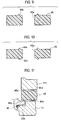
- the packing member 45 shown in FIG. 7 and FIG. 8 is a first configuration example, and is provided with the protrusion 45b only on the upper surface thereof.
- FIG. 9 only shows the packing member 45 of the first configuration example.
- the protrusion 45b in the first configuration example is substantially triangular in cross-section.
- the packing member 45 is held and pressed by the upper surface 101t of the case body 101, and the chassis 11 and the flange 30b. Therefore, the protrusion 45b substantially triangular in cross-section is crushed as shown in FIG. 7 and FIG. 8 .
- the packing member 45 is held and pressed by the upper surface 101t of the case body 101, and the chassis 11 and flange 30b, as described above.
- the member by which the packing member 45 is held together with the chassis 11 and the flange 30b is not limited to the case body 101.
- the packing member 45 may be interposed between the chassis 11 and the flange 30b, and the other member (an arbitrary member) opposed to the chassis 11 and the flange 30b.
- the waterproof and dustproof effect can be further improved by the packing member 45.
- the flat surface on the underside of the flange 30b of the nut 30 is in direct contact with the flat surface 13 formed in the chassis 11, and the upper flat surface of the flange 30b is in direct contact with the packing member 45. These direct contacts cause friction and therefore the nut 30 is not easily loosened in the second embodiment.
- FIG. 10 shows a second configuration example of the packing member 45.
- the packing member 45 in the second configuration example is provided with a ring-like protrusion 45b on the upper surface adjacent to the opening 45a, and provided with a ring-like protrusion 45c on the lower surface adjacent to the opening 45a.
- the protrusion 45b and the protrusion 45c are provided in opposed positions.
- FIG. 11 shows a third configuration example of the packing member 45.
- FIG. 11 is an enlarged partial view of the right part of FIG. 7 and FIG. 8 .
- the packing member 45 in the third configuration example is provided with a protrusion 45d on the upper surface and a protrusion 45e on the lower surface in positions away from the opening 45a, in addition to the protrusions 45b and 45c provided in the same manner as the second configuration example.
- the protrusion 45d and the protrusion 45e are provided in opposed positions.
- the protrusions 45b and 45c are located in positions opposed to the flange 30b, and the protrusions 45d and 45e are located in positions opposed to the chassis 11.
- the protrusions 45b to 45e in the first to third configuration examples of the packing member 45 are substantially triangular in cross-section, the shape of these protrusions is not particularly limited.
- the tipsof the protrusions 45b to 45e may be curved in cross-section to have an arc-like shape.
- the packing member 45 may be deformed to serve as a torque control member that controls torque when rotating the knob 50, as described in JP 2009-135356 A .
- the packing member 45 is provided across the chassis 11 and the flange 30b of the nut 30 as a fastening member, and held by the chassis 11 and the upper surface 101t of the case body 101. The packing member 45 is then pressed against the inner wall of the knob 50 or the turn operation shaft 21b so as to be deformed. In this case, the packing member 45 does not necessarily have a waterproof and dustproof effect.
- the electronic apparatus and the fixing structure according to the first and second embodiments can prevent the entrance of water and dust effectively while minimizing the number of components.
- the present invention is not limited to the first and second embodiments described above, and various modifications and improvements may be made within the scope of the present invention.
- the fixing structure for fixing the insertion member to the receiving member has been explained as the waterproof and dustproof structure in the first and second embodiments. However, it is apparent that the fixing structure according to the first and second embodiments can prevent the entrance of other liquids such as oil instead of water.
- the fixing structure according to the first and second embodiment is applicable to other electronic apparatuses such as acoustic consoles other than the radio device 100, and also applicable to purposes other than electronic apparatuses.
- the fixing structure according to the first and second embodiments may be used for piping of in-vehicle radio devices or shaft fixtures such as oil pipes.
- the fixing structure may be provided with any other waterproof and dustproof members in order to improve the waterproof and dustproof effect. It is obvious that the present invention is not limited to the configuration in which the waterproof and dustproof structure is achieved only by two O-rings, or only by two O-rings and a packing member.
Landscapes
- Engineering & Computer Science (AREA)
- General Engineering & Computer Science (AREA)
- Microelectronics & Electronic Packaging (AREA)
- Mechanical Engineering (AREA)
- Casings For Electric Apparatus (AREA)
- Telephone Set Structure (AREA)
- Connection Of Plates (AREA)
Claims (9)
- Elektronische Vorrichtung, die aufweist:ein Aufnahmeelement (11) mit einer Öffnung (11a);ein Einführelement (21), das durch die Öffnung (11a) eingeführt wird und mit einem Außengewinde an einer Umfangsfläche davon vorgesehen ist; undein Befestigungselement (30), das mit einem Innengewinde an einer Innenfläche davon vorgesehen ist, das mit dem Außengewinde schraubbar in Eingriff ist, das ausgebildet ist zum Befestigen des Einführelements (21) an dem Aufnahmeelement (11), indem das Innengewinde mit dem Außengewinde in Eingriff gebracht wird, und ausgebildet ist zum Abdecken der Öffnung (11a);dadurch gekennzeichnet, dass die elektronische Vorrichtung weiter aufweist einen ersten O-Ring (41), der zwischen dem Einführelement (21) und dem Befestigungselement (30) positioniert ist, und einen zweiten O-Ring (42), der zwischen dem Befestigungselement (30) und dem Aufnahmeelement (11) positioniert ist, in einem Zustand, in dem das Einführelement (21) durch das Befestigungselement (30) befestigt ist,wobei, bei Betrachtung jedes kreisförmigen Querschnitts des ersten und zweiten O-Rings (41, 42) entlang einer Oberfläche parallel zu einer Bewegungsrichtung des Befestigungselements (30) bei einem Befestigen des Einführelements (21) durch Rotieren des Befestigungselements (30), ein erster Punkt jedes kreisförmigen Querschnitts gegen eine Oberfläche senkrecht zu der Bewegungsrichtung gedrückt wird, undeine Position versetzt von einem zweiten Punkt gegenüber dem ersten Punkt jedes kreisförmigen Querschnitts gegen eine geneigte Oberfläche (12, 32) gedrückt wird, die zu der Bewegungsrichtung geneigt ist,wobei das Einführelement (21) mit einem ersten Halteabschnitt (22) vorgesehen ist, der in einer diametralen Richtung des Einführelements (21) ausgespart ist, um den ersten O-Ring (41) zu halten, undwobei das Befestigungselement (30) mit einem zweiten Halteabschnitt (31) vorgesehen ist, der in einer diametralen Richtung des Befestigungselements (30) ausgespart ist, um den zweiten O-Ring (42) zu halten.
- Die elektronische Vorrichtung gemäß Anspruch 1, wobei:der erste O-Ring (41) an dem Einführelement (21) angebracht ist und der zweite O-Ring (42) an dem Befestigungselement (30) angebracht ist,das Befestigungselement (30) mit einer ersten geneigten Oberfläche (32) vorgesehen ist, die ausgebildet ist, mit der von dem zweiten Punkt des ersten O-Rings (41) versetzten Position in Kontakt zu kommen, unddas Aufnahmeelement (11) mit einer zweiten geneigten Oberfläche (12) vorgesehen ist, die ausgebildet ist, mit der von dem zweiten Punkt des zweiten O-Rings (42) versetzten Position in Kontakt zu kommen.
- Die elektronische Vorrichtung gemäß Anspruch 2, wobei:das Einführelement (21) einen Hauptkörper (21a) mit einer Seite, die länger als ein Durchmesser der Öffnung (11a) ist, eine rotierbare Drehbetriebswelle (21b), die aus dem Hauptkörper (21a) herausragt und durch die Öffnung (11a) eingeführt ist, und ein Außengewindeformationselement (21c) aufweist, das mit dem Außengewinde an einer Umfangsfläche davon vorgesehen ist, an einer Umfangsfläche der Drehbetriebswelle (21b) vorgesehen und an dem Hauptkörper (21a) befestigt,das Befestigungselement (30) einen zylindrischen Teil (30a1, 30a2) und einen Flansch (30b) umfasst, der aus dem zylindrischen Teil (30a1, 30a2) herausragt,der erste O-Ring (41) in einer Ecke des Hauptkörpers (21a) und des Außengewindeformationselements (21c) angeordnet ist,die erste geneigte Oberfläche (32) auf einer Innenfläche vorgesehen ist, die an einen dem Hauptkörper (21a) zugewandten Boden des zylindrischen Teils (30a2) angrenzt,der zweite O-Ring (42) in einer Ecke einer Oberfläche des Flansches (30b) angeordnet ist, die dem Aufnahmeelement (11) und einer Umfangsfläche des zylindrischen Teils (30a2) zugewandt ist, unddie zweite geneigte Oberfläche (12) an einer Kante der Öffnung (11a) des Aufnahmeelements (11) vorgesehen ist.
- Die elektronische Vorrichtung gemäß einem von Anspruch 3, wobei:das Aufnahmeelement (11) und das Befestigungselement (30) aus Metall bestehen,das Aufnahmeelement (11) mit einer ersten ebenen Oberfläche (13) parallel zu einer Richtung senkrecht zu der Bewegungsrichtung vorgesehen ist,die dem Aufnahmeelement (11) zugewandte Oberfläche des Flansches (30b) eine zweite ebene Oberfläche gegenüber der ersten ebenen Oberfläche (13) ist, unddie erste ebene Oberfläche (13) mit der zweiten ebenen Oberfläche auf einer Außenseite des Flansches (30b) entfernt von dem zweiten O-Ring (42) in Kontakt kommt.
- Die elektronische Vorrichtung gemäß den Ansprüchen 1 bis 4, wobei das Aufnahmeelement (11) mit einem Aussparungsteil (14) vorgesehen ist, der in der Bewegungsrichtung ausgespart ist, um den Flansch (30b) zu halten.
- Die elektronische Vorrichtung gemäß Anspruch 3 oder 4, wobei:der Hauptkörper (21a) eine Schaltung umfasst, die die elektronische Vorrichtung auf einen vorgegebenen Einstellzustand anpasst, unddie Drehbetriebswelle (21b) mit einem Knopf (50) vorgesehen ist, der die Drehbetriebswelle (21b) rotiert, um den vorgegebenen Einstellzustand zu steuern.
- Die elektronische Vorrichtung gemäß einem der Ansprüche 1 bis 6, die weiter ein Packungselement (45), das das Aufnahmeelement (11) und das Befestigungselement (30) überbrückt und von dem Aufnahmeelement (11) und dem Befestigungselement (30) gehalten und gedrückt wird, und ein arbiträres Element gegenüber dem Aufnahmeelement (11) und dem Befestigungselement (30) aufweist.
- Die elektronische Vorrichtung gemäß Anspruch 7, wobei das Packungselement (45) mit einem Vorsprung (45b) vorgesehen ist, der dem arbiträren Element zugewandt ist und zu diesem hin ragt.
- Die elektronische Vorrichtung gemäß Anspruch 8, wobei der Vorsprung (45b) in einer Position gegenüber der zweiten ebenen Oberfläche ausgebildet ist.
Applications Claiming Priority (2)
| Application Number | Priority Date | Filing Date | Title |
|---|---|---|---|
| JP2012073556A JP5861533B2 (ja) | 2012-03-28 | 2012-03-28 | 電子機器及び固定構造 |
| JP2012109294A JP5825193B2 (ja) | 2012-05-11 | 2012-05-11 | 電子機器及び固定構造 |
Publications (3)
| Publication Number | Publication Date |
|---|---|
| EP2645835A2 EP2645835A2 (de) | 2013-10-02 |
| EP2645835A3 EP2645835A3 (de) | 2018-01-17 |
| EP2645835B1 true EP2645835B1 (de) | 2020-05-06 |
Family
ID=48141712
Family Applications (1)
| Application Number | Title | Priority Date | Filing Date |
|---|---|---|---|
| EP13001520.9A Active EP2645835B1 (de) | 2012-03-28 | 2013-03-25 | Elektronische Vorrichtung und Befestigungsstruktur |
Country Status (2)
| Country | Link |
|---|---|
| US (1) | US8917525B2 (de) |
| EP (1) | EP2645835B1 (de) |
Family Cites Families (12)
| Publication number | Priority date | Publication date | Assignee | Title |
|---|---|---|---|---|
| US4529346A (en) * | 1983-07-22 | 1985-07-16 | Borg-Warner Corporation | Securing assembly for a threaded member |
| JPH0414862U (de) * | 1990-05-28 | 1992-02-06 | ||
| US5173536A (en) | 1990-12-11 | 1992-12-22 | Union Carbide Chemicals & Plastics Technology Corporation | Impact polymer blend |
| FR2714519B1 (fr) * | 1993-12-29 | 1996-02-02 | Alcatel Mobile Comm France | Bouton de commutation à blocage étanche sur son support. |
| JP3031461B2 (ja) | 1997-10-24 | 2000-04-10 | 日本電気株式会社 | 防水型コネクタ |
| JP2004286376A (ja) | 2003-03-24 | 2004-10-14 | Sanyo Electric Co Ltd | スターリング冷凍機 |
| JP4323237B2 (ja) | 2003-07-11 | 2009-09-02 | 株式会社ケンウッド | 回転操作軸の変形防止機構 |
| US20070081804A1 (en) * | 2005-10-07 | 2007-04-12 | Universal Scientific Industrial Co., Ltd. | Electronic device including a rotatable camera unit |
| US8152515B2 (en) * | 2007-03-15 | 2012-04-10 | Continental Appliances Inc | Fuel selectable heating devices |
| US7819134B2 (en) * | 2007-09-04 | 2010-10-26 | Masco Corporation Of Indiana | Valve fitting with integral stops |
| JP5109629B2 (ja) | 2007-12-03 | 2012-12-26 | 株式会社Jvcケンウッド | 携帯通信機用回転つまみの回転トルク調整装置 |
| US7886903B1 (en) * | 2008-09-19 | 2011-02-15 | Aileron Designs, LLC | Articulated notebook computer cover and mounting device |
-
2013
- 2013-03-15 US US13/835,947 patent/US8917525B2/en active Active
- 2013-03-25 EP EP13001520.9A patent/EP2645835B1/de active Active
Non-Patent Citations (1)
| Title |
|---|
| None * |
Also Published As
| Publication number | Publication date |
|---|---|
| EP2645835A2 (de) | 2013-10-02 |
| US8917525B2 (en) | 2014-12-23 |
| US20130258633A1 (en) | 2013-10-03 |
| EP2645835A3 (de) | 2018-01-17 |
Similar Documents
| Publication | Publication Date | Title |
|---|---|---|
| US7874537B2 (en) | Swivel device and video display apparatus equipped with swivel device | |
| US20150027868A1 (en) | Button, button arrangement and electronic device employing same | |
| US8604362B2 (en) | Waterproof assembly and device employing the same | |
| CN204717264U (zh) | 旋转范围限制装置和包括其和构造体的装置 | |
| EP3061999A1 (de) | Abdeckstopfen | |
| KR20080029785A (ko) | 방수구조 | |
| JP6774037B2 (ja) | 防水型コネクタ | |
| US20170154740A1 (en) | Push-button structure and electronic device with the same | |
| US10644277B2 (en) | Housing and electronic device with mounting structure for mounting battery | |
| US8513555B2 (en) | Power button and electronic device using same | |
| JP5782979B2 (ja) | 電気機器 | |
| US8434217B2 (en) | Mounting apparatus for circuit board | |
| EP2645835B1 (de) | Elektronische Vorrichtung und Befestigungsstruktur | |
| US20150063618A1 (en) | Housing assembly | |
| CN103697026A (zh) | 按钮式开关、选择开关,以及用于它们的固定元件 | |
| US8553399B2 (en) | Electronic device with locking assembly | |
| US20160060953A1 (en) | Waterproof door structures and devices with the same | |
| CN103329372A (zh) | 电气控制或信号设备 | |
| US20130010437A1 (en) | Mounting apparatus for circuit board | |
| JP2010147092A (ja) | 筐体締結ねじ部防水構造及び携帯機器 | |
| JP5081679B2 (ja) | 防水シール構造およびこのシール構造を設けた機器 | |
| US20100330406A1 (en) | Electronic device with battery | |
| US20230205060A1 (en) | Camera mount assembly and method for assembling camera mount | |
| JP2019110618A (ja) | 遮音カバー、遮音装置、配線器具の設置構造及び配線器具を設置する方法 | |
| JPWO2012133702A1 (ja) | 基地局装置および蓋の取り付け方法 |
Legal Events
| Date | Code | Title | Description |
|---|---|---|---|
| PUAI | Public reference made under article 153(3) epc to a published international application that has entered the european phase |
Free format text: ORIGINAL CODE: 0009012 |
|
| AK | Designated contracting states |
Kind code of ref document: A2 Designated state(s): AL AT BE BG CH CY CZ DE DK EE ES FI FR GB GR HR HU IE IS IT LI LT LU LV MC MK MT NL NO PL PT RO RS SE SI SK SM TR |
|
| AX | Request for extension of the european patent |
Extension state: BA ME |
|
| PUAL | Search report despatched |
Free format text: ORIGINAL CODE: 0009013 |
|
| AK | Designated contracting states |
Kind code of ref document: A3 Designated state(s): AL AT BE BG CH CY CZ DE DK EE ES FI FR GB GR HR HU IE IS IT LI LT LU LV MC MK MT NL NO PL PT RO RS SE SI SK SM TR |
|
| AX | Request for extension of the european patent |
Extension state: BA ME |
|
| RIC1 | Information provided on ipc code assigned before grant |
Ipc: H01C 10/14 20060101ALI20171214BHEP Ipc: H05K 5/06 20060101AFI20171214BHEP Ipc: G05G 1/10 20060101ALI20171214BHEP |
|
| 17P | Request for examination filed |
Effective date: 20180427 |
|
| RBV | Designated contracting states (corrected) |
Designated state(s): AL AT BE BG CH CY CZ DE DK EE ES FI FR GB GR HR HU IE IS IT LI LT LU LV MC MK MT NL NO PL PT RO RS SE SI SK SM TR |
|
| RIC1 | Information provided on ipc code assigned before grant |
Ipc: H05K 5/06 20060101AFI20191104BHEP Ipc: H01C 10/14 20060101ALI20191104BHEP Ipc: G05G 25/04 20060101ALI20191104BHEP Ipc: G05G 1/10 20060101ALI20191104BHEP |
|
| GRAP | Despatch of communication of intention to grant a patent |
Free format text: ORIGINAL CODE: EPIDOSNIGR1 |
|
| STAA | Information on the status of an ep patent application or granted ep patent |
Free format text: STATUS: GRANT OF PATENT IS INTENDED |
|
| INTG | Intention to grant announced |
Effective date: 20191216 |
|
| GRAS | Grant fee paid |
Free format text: ORIGINAL CODE: EPIDOSNIGR3 |
|
| GRAA | (expected) grant |
Free format text: ORIGINAL CODE: 0009210 |
|
| STAA | Information on the status of an ep patent application or granted ep patent |
Free format text: STATUS: THE PATENT HAS BEEN GRANTED |
|
| AK | Designated contracting states |
Kind code of ref document: B1 Designated state(s): AL AT BE BG CH CY CZ DE DK EE ES FI FR GB GR HR HU IE IS IT LI LT LU LV MC MK MT NL NO PL PT RO RS SE SI SK SM TR |
|
| REG | Reference to a national code |
Ref country code: GB Ref legal event code: FG4D |
|
| REG | Reference to a national code |
Ref country code: CH Ref legal event code: EP Ref country code: AT Ref legal event code: REF Ref document number: 1268958 Country of ref document: AT Kind code of ref document: T Effective date: 20200515 |
|
| REG | Reference to a national code |
Ref country code: IE Ref legal event code: FG4D |
|
| REG | Reference to a national code |
Ref country code: DE Ref legal event code: R096 Ref document number: 602013068623 Country of ref document: DE |
|
| REG | Reference to a national code |
Ref country code: LT Ref legal event code: MG4D |
|
| REG | Reference to a national code |
Ref country code: NL Ref legal event code: MP Effective date: 20200506 |
|
| PG25 | Lapsed in a contracting state [announced via postgrant information from national office to epo] |
Ref country code: IS Free format text: LAPSE BECAUSE OF FAILURE TO SUBMIT A TRANSLATION OF THE DESCRIPTION OR TO PAY THE FEE WITHIN THE PRESCRIBED TIME-LIMIT Effective date: 20200906 Ref country code: PT Free format text: LAPSE BECAUSE OF FAILURE TO SUBMIT A TRANSLATION OF THE DESCRIPTION OR TO PAY THE FEE WITHIN THE PRESCRIBED TIME-LIMIT Effective date: 20200907 Ref country code: NO Free format text: LAPSE BECAUSE OF FAILURE TO SUBMIT A TRANSLATION OF THE DESCRIPTION OR TO PAY THE FEE WITHIN THE PRESCRIBED TIME-LIMIT Effective date: 20200806 Ref country code: GR Free format text: LAPSE BECAUSE OF FAILURE TO SUBMIT A TRANSLATION OF THE DESCRIPTION OR TO PAY THE FEE WITHIN THE PRESCRIBED TIME-LIMIT Effective date: 20200807 Ref country code: LT Free format text: LAPSE BECAUSE OF FAILURE TO SUBMIT A TRANSLATION OF THE DESCRIPTION OR TO PAY THE FEE WITHIN THE PRESCRIBED TIME-LIMIT Effective date: 20200506 Ref country code: SE Free format text: LAPSE BECAUSE OF FAILURE TO SUBMIT A TRANSLATION OF THE DESCRIPTION OR TO PAY THE FEE WITHIN THE PRESCRIBED TIME-LIMIT Effective date: 20200506 Ref country code: FI Free format text: LAPSE BECAUSE OF FAILURE TO SUBMIT A TRANSLATION OF THE DESCRIPTION OR TO PAY THE FEE WITHIN THE PRESCRIBED TIME-LIMIT Effective date: 20200506 |
|
| PG25 | Lapsed in a contracting state [announced via postgrant information from national office to epo] |
Ref country code: BG Free format text: LAPSE BECAUSE OF FAILURE TO SUBMIT A TRANSLATION OF THE DESCRIPTION OR TO PAY THE FEE WITHIN THE PRESCRIBED TIME-LIMIT Effective date: 20200806 Ref country code: HR Free format text: LAPSE BECAUSE OF FAILURE TO SUBMIT A TRANSLATION OF THE DESCRIPTION OR TO PAY THE FEE WITHIN THE PRESCRIBED TIME-LIMIT Effective date: 20200506 Ref country code: LV Free format text: LAPSE BECAUSE OF FAILURE TO SUBMIT A TRANSLATION OF THE DESCRIPTION OR TO PAY THE FEE WITHIN THE PRESCRIBED TIME-LIMIT Effective date: 20200506 Ref country code: RS Free format text: LAPSE BECAUSE OF FAILURE TO SUBMIT A TRANSLATION OF THE DESCRIPTION OR TO PAY THE FEE WITHIN THE PRESCRIBED TIME-LIMIT Effective date: 20200506 |
|
| REG | Reference to a national code |
Ref country code: AT Ref legal event code: MK05 Ref document number: 1268958 Country of ref document: AT Kind code of ref document: T Effective date: 20200506 |
|
| PG25 | Lapsed in a contracting state [announced via postgrant information from national office to epo] |
Ref country code: AL Free format text: LAPSE BECAUSE OF FAILURE TO SUBMIT A TRANSLATION OF THE DESCRIPTION OR TO PAY THE FEE WITHIN THE PRESCRIBED TIME-LIMIT Effective date: 20200506 Ref country code: NL Free format text: LAPSE BECAUSE OF FAILURE TO SUBMIT A TRANSLATION OF THE DESCRIPTION OR TO PAY THE FEE WITHIN THE PRESCRIBED TIME-LIMIT Effective date: 20200506 |
|
| PG25 | Lapsed in a contracting state [announced via postgrant information from national office to epo] |
Ref country code: AT Free format text: LAPSE BECAUSE OF FAILURE TO SUBMIT A TRANSLATION OF THE DESCRIPTION OR TO PAY THE FEE WITHIN THE PRESCRIBED TIME-LIMIT Effective date: 20200506 Ref country code: ES Free format text: LAPSE BECAUSE OF FAILURE TO SUBMIT A TRANSLATION OF THE DESCRIPTION OR TO PAY THE FEE WITHIN THE PRESCRIBED TIME-LIMIT Effective date: 20200506 Ref country code: RO Free format text: LAPSE BECAUSE OF FAILURE TO SUBMIT A TRANSLATION OF THE DESCRIPTION OR TO PAY THE FEE WITHIN THE PRESCRIBED TIME-LIMIT Effective date: 20200506 Ref country code: IT Free format text: LAPSE BECAUSE OF FAILURE TO SUBMIT A TRANSLATION OF THE DESCRIPTION OR TO PAY THE FEE WITHIN THE PRESCRIBED TIME-LIMIT Effective date: 20200506 Ref country code: CZ Free format text: LAPSE BECAUSE OF FAILURE TO SUBMIT A TRANSLATION OF THE DESCRIPTION OR TO PAY THE FEE WITHIN THE PRESCRIBED TIME-LIMIT Effective date: 20200506 Ref country code: SM Free format text: LAPSE BECAUSE OF FAILURE TO SUBMIT A TRANSLATION OF THE DESCRIPTION OR TO PAY THE FEE WITHIN THE PRESCRIBED TIME-LIMIT Effective date: 20200506 Ref country code: EE Free format text: LAPSE BECAUSE OF FAILURE TO SUBMIT A TRANSLATION OF THE DESCRIPTION OR TO PAY THE FEE WITHIN THE PRESCRIBED TIME-LIMIT Effective date: 20200506 Ref country code: DK Free format text: LAPSE BECAUSE OF FAILURE TO SUBMIT A TRANSLATION OF THE DESCRIPTION OR TO PAY THE FEE WITHIN THE PRESCRIBED TIME-LIMIT Effective date: 20200506 |
|
| REG | Reference to a national code |
Ref country code: DE Ref legal event code: R097 Ref document number: 602013068623 Country of ref document: DE |
|
| PG25 | Lapsed in a contracting state [announced via postgrant information from national office to epo] |
Ref country code: SK Free format text: LAPSE BECAUSE OF FAILURE TO SUBMIT A TRANSLATION OF THE DESCRIPTION OR TO PAY THE FEE WITHIN THE PRESCRIBED TIME-LIMIT Effective date: 20200506 Ref country code: PL Free format text: LAPSE BECAUSE OF FAILURE TO SUBMIT A TRANSLATION OF THE DESCRIPTION OR TO PAY THE FEE WITHIN THE PRESCRIBED TIME-LIMIT Effective date: 20200506 |
|
| PLBE | No opposition filed within time limit |
Free format text: ORIGINAL CODE: 0009261 |
|
| STAA | Information on the status of an ep patent application or granted ep patent |
Free format text: STATUS: NO OPPOSITION FILED WITHIN TIME LIMIT |
|
| 26N | No opposition filed |
Effective date: 20210209 |
|
| PG25 | Lapsed in a contracting state [announced via postgrant information from national office to epo] |
Ref country code: SI Free format text: LAPSE BECAUSE OF FAILURE TO SUBMIT A TRANSLATION OF THE DESCRIPTION OR TO PAY THE FEE WITHIN THE PRESCRIBED TIME-LIMIT Effective date: 20200506 |
|
| PG25 | Lapsed in a contracting state [announced via postgrant information from national office to epo] |
Ref country code: MC Free format text: LAPSE BECAUSE OF FAILURE TO SUBMIT A TRANSLATION OF THE DESCRIPTION OR TO PAY THE FEE WITHIN THE PRESCRIBED TIME-LIMIT Effective date: 20200506 |
|
| REG | Reference to a national code |
Ref country code: CH Ref legal event code: PL |
|
| GBPC | Gb: european patent ceased through non-payment of renewal fee |
Effective date: 20210325 |
|
| REG | Reference to a national code |
Ref country code: BE Ref legal event code: MM Effective date: 20210331 |
|
| PG25 | Lapsed in a contracting state [announced via postgrant information from national office to epo] |
Ref country code: CH Free format text: LAPSE BECAUSE OF NON-PAYMENT OF DUE FEES Effective date: 20210331 Ref country code: LI Free format text: LAPSE BECAUSE OF NON-PAYMENT OF DUE FEES Effective date: 20210331 Ref country code: LU Free format text: LAPSE BECAUSE OF NON-PAYMENT OF DUE FEES Effective date: 20210325 Ref country code: GB Free format text: LAPSE BECAUSE OF NON-PAYMENT OF DUE FEES Effective date: 20210325 Ref country code: IE Free format text: LAPSE BECAUSE OF NON-PAYMENT OF DUE FEES Effective date: 20210325 Ref country code: FR Free format text: LAPSE BECAUSE OF NON-PAYMENT OF DUE FEES Effective date: 20210331 |
|
| PG25 | Lapsed in a contracting state [announced via postgrant information from national office to epo] |
Ref country code: BE Free format text: LAPSE BECAUSE OF NON-PAYMENT OF DUE FEES Effective date: 20210331 |
|
| PG25 | Lapsed in a contracting state [announced via postgrant information from national office to epo] |
Ref country code: HU Free format text: LAPSE BECAUSE OF FAILURE TO SUBMIT A TRANSLATION OF THE DESCRIPTION OR TO PAY THE FEE WITHIN THE PRESCRIBED TIME-LIMIT; INVALID AB INITIO Effective date: 20130325 |
|
| PG25 | Lapsed in a contracting state [announced via postgrant information from national office to epo] |
Ref country code: CY Free format text: LAPSE BECAUSE OF FAILURE TO SUBMIT A TRANSLATION OF THE DESCRIPTION OR TO PAY THE FEE WITHIN THE PRESCRIBED TIME-LIMIT Effective date: 20200506 |
|
| PG25 | Lapsed in a contracting state [announced via postgrant information from national office to epo] |
Ref country code: MK Free format text: LAPSE BECAUSE OF FAILURE TO SUBMIT A TRANSLATION OF THE DESCRIPTION OR TO PAY THE FEE WITHIN THE PRESCRIBED TIME-LIMIT Effective date: 20200506 |
|
| PG25 | Lapsed in a contracting state [announced via postgrant information from national office to epo] |
Ref country code: TR Free format text: LAPSE BECAUSE OF FAILURE TO SUBMIT A TRANSLATION OF THE DESCRIPTION OR TO PAY THE FEE WITHIN THE PRESCRIBED TIME-LIMIT Effective date: 20200506 |
|
| PG25 | Lapsed in a contracting state [announced via postgrant information from national office to epo] |
Ref country code: MT Free format text: LAPSE BECAUSE OF FAILURE TO SUBMIT A TRANSLATION OF THE DESCRIPTION OR TO PAY THE FEE WITHIN THE PRESCRIBED TIME-LIMIT Effective date: 20200506 |
|
| PGFP | Annual fee paid to national office [announced via postgrant information from national office to epo] |
Ref country code: DE Payment date: 20250128 Year of fee payment: 13 |