EP2645394A1 - Power circuit interrupting device - Google Patents
Power circuit interrupting device Download PDFInfo
- Publication number
- EP2645394A1 EP2645394A1 EP11843693.0A EP11843693A EP2645394A1 EP 2645394 A1 EP2645394 A1 EP 2645394A1 EP 11843693 A EP11843693 A EP 11843693A EP 2645394 A1 EP2645394 A1 EP 2645394A1
- Authority
- EP
- European Patent Office
- Prior art keywords
- fuse
- housing
- power circuit
- continuity test
- interrupting device
- Prior art date
- Legal status (The legal status is an assumption and is not a legal conclusion. Google has not performed a legal analysis and makes no representation as to the accuracy of the status listed.)
- Granted
Links
- 230000008878 coupling Effects 0.000 claims description 4
- 238000010168 coupling process Methods 0.000 claims description 4
- 238000005859 coupling reaction Methods 0.000 claims description 4
- 238000012423 maintenance Methods 0.000 abstract description 4
- 238000000034 method Methods 0.000 abstract description 3
- 230000002093 peripheral effect Effects 0.000 description 16
- 239000000523 sample Substances 0.000 description 15
- 238000010586 diagram Methods 0.000 description 6
- 239000004020 conductor Substances 0.000 description 5
- 239000000463 material Substances 0.000 description 4
- 238000010276 construction Methods 0.000 description 3
- 239000000428 dust Substances 0.000 description 3
- 238000010998 test method Methods 0.000 description 3
- XLYOFNOQVPJJNP-UHFFFAOYSA-N water Substances O XLYOFNOQVPJJNP-UHFFFAOYSA-N 0.000 description 2
- 235000001537 Ribes X gardonianum Nutrition 0.000 description 1
- 235000001535 Ribes X utile Nutrition 0.000 description 1
- 235000016919 Ribes petraeum Nutrition 0.000 description 1
- 244000281247 Ribes rubrum Species 0.000 description 1
- 235000002355 Ribes spicatum Nutrition 0.000 description 1
- 230000000694 effects Effects 0.000 description 1
- 238000003780 insertion Methods 0.000 description 1
- 230000037431 insertion Effects 0.000 description 1
- 238000007789 sealing Methods 0.000 description 1
Images



Classifications
-
- H—ELECTRICITY
- H01—ELECTRIC ELEMENTS
- H01H—ELECTRIC SWITCHES; RELAYS; SELECTORS; EMERGENCY PROTECTIVE DEVICES
- H01H85/00—Protective devices in which the current flows through a part of fusible material and this current is interrupted by displacement of the fusible material when this current becomes excessive
- H01H85/02—Details
-
- H—ELECTRICITY
- H01—ELECTRIC ELEMENTS
- H01H—ELECTRIC SWITCHES; RELAYS; SELECTORS; EMERGENCY PROTECTIVE DEVICES
- H01H9/00—Details of switching devices, not covered by groups H01H1/00 - H01H7/00
- H01H9/08—Arrangements to facilitate replacement of a switch, e.g. cartridge housing
- H01H9/085—Arrangements to facilitate replacement of a switch, e.g. cartridge housing contact separation effected by removing contact carrying element
-
- H—ELECTRICITY
- H01—ELECTRIC ELEMENTS
- H01H—ELECTRIC SWITCHES; RELAYS; SELECTORS; EMERGENCY PROTECTIVE DEVICES
- H01H85/00—Protective devices in which the current flows through a part of fusible material and this current is interrupted by displacement of the fusible material when this current becomes excessive
- H01H85/02—Details
- H01H85/0241—Structural association of a fuse and another component or apparatus
-
- H—ELECTRICITY
- H01—ELECTRIC ELEMENTS
- H01H—ELECTRIC SWITCHES; RELAYS; SELECTORS; EMERGENCY PROTECTIVE DEVICES
- H01H31/00—Air-break switches for high tension without arc-extinguishing or arc-preventing means
- H01H31/14—Air-break switches for high tension without arc-extinguishing or arc-preventing means with bridging contact that is not electrically connected to either line contact in open position of switch
- H01H31/24—Air-break switches for high tension without arc-extinguishing or arc-preventing means with bridging contact that is not electrically connected to either line contact in open position of switch with rectilinearly-movable bridging contact
-
- H—ELECTRICITY
- H01—ELECTRIC ELEMENTS
- H01H—ELECTRIC SWITCHES; RELAYS; SELECTORS; EMERGENCY PROTECTIVE DEVICES
- H01H9/00—Details of switching devices, not covered by groups H01H1/00 - H01H7/00
- H01H9/10—Adaptation for built-in fuses
-
- H—ELECTRICITY
- H01—ELECTRIC ELEMENTS
- H01H—ELECTRIC SWITCHES; RELAYS; SELECTORS; EMERGENCY PROTECTIVE DEVICES
- H01H85/00—Protective devices in which the current flows through a part of fusible material and this current is interrupted by displacement of the fusible material when this current becomes excessive
- H01H85/02—Details
- H01H85/20—Bases for supporting the fuse; Separate parts thereof
- H01H85/205—Electric connections to contacts on the base
- H01H2085/206—Electric connections to contacts on the base being tappable, e.g. terminals on the fuse or base being arranged so as to permit an additional connector to be engaged therewith
-
- H—ELECTRICITY
- H01—ELECTRIC ELEMENTS
- H01H—ELECTRIC SWITCHES; RELAYS; SELECTORS; EMERGENCY PROTECTIVE DEVICES
- H01H9/00—Details of switching devices, not covered by groups H01H1/00 - H01H7/00
- H01H9/10—Adaptation for built-in fuses
- H01H9/102—Fuses mounted on or constituting the movable contact parts of the switch
Definitions
- the present invention relates to a power circuit interrupting device that electrically connects and disconnects a power circuit of a hybrid motor vehicle, an electric motor vehicle, etc.
- Patent Literature 1 Upon carrying out a maintenance work of a hybrid motor vesicle, an electric motor vehicle, etc., a power circuit must be brought into interruption by a manual operation in order to ensure safe of a maintenance worker.
- a power circuit interrupting device as described in the following Patent Literature 1 is known.
- the device as described in Patent Literature 1 includes a pair of fixed electrodes and a fuse which are disposed in a casing, a moveable electrode capable of being coupled to the fixed electrodes to establish electrical connection between the fixed electrodes and being uncoupled from the fixed electrodes to interrupt the electrical connection therebetween, and a coupling/uncoupling operation handle provided with the moveable electrode.
- the device is constructed such that a conduction path is accommodated within the casing when an electrical continuity is established, and therefore, the device is excellent in view of safety.
- the fuse is disposed within the casing. Due to this construction, in order to carry out a continuity test for the fuse, it is necessary to uncouple the moveable electrode from the fixed electrodes, loosen screws, and open the casing to thereby expose the fuse outside. Accordingly, it takes a long time for performing the test procedure.
- Patent Literature 1 Japanese Patent Application Unexamined Publication No. 9-265874
- a power circuit interrupting device includes a first housing including a pair of fixed electrodes and a fuse, and a second housing including a moveable electrode, the moveable electrode interrupting electrical connection between the fixed electrodes when the second housing is uncoupled from the first housing, and establishing the electrical connection between the fixed electrodes when the second housing is coupled with the first housing.
- the first housing has an opening provided for carrying out a continuity test for the fuse. The opening is covered with the second housing in a condition that continuity of a circuit is allowed.
- the device it is possible to carry out a continuity test for the fuse without exposing a whole portion of the fuse. Therefore, the device can serve to reduce a time for performing the test procedure. Further, in order to carry out the continuity test, the second housing having the moveable electrode must be uncoupled from the first housing, whereby the device can serve to keep safety. In addition, since the opening for the continuity test is covered with the second housing in a normal condition in which continuity of the power circuit is allowed, a foreign material such as dust can be prevented from entering into the device.
- FIG. 1 is an electric circuit diagram showing a part of a power circuit of a hybrid vehicle, an electric vehicle, etc.
- Service disconnect switch (hereinafter referred to as simply "SDSW”) 1 is a power circuit interrupting device according to the present invention.
- SDSW 1 serves as a breaker device that constitutes a part of battery pack 2 and is disposed in a power circuit to interrupt or establish electrical connection between batteries, and can interrupt continuity of the power circuit including a fuse.
- SDSW 1 includes first housing 3 including a pair of fixed electrodes and fuse 5, and second housing 4 including a moveable electrode that is uncoupled from the fixed electrodes to disconnect the fixed electrodes from each other or coupled with the fixed electrodes to connect the fixed electrodes with each other.
- a work of a continuity test can be safely performed by interrupting the electrical connection between batteries by uncoupling the moveable electrode from the fixed electrodes through second housing 4 or establishing the electrical connection between batteries by coupling the moveable electrode with the fixed electrodes through second housing 4.
- electric currant from the batteries flows to an inverter and a DC/DC converter through a main relay.
- FIG. 2a is a perspective view of SDSW 1 as a whole according to the embodiment.
- SDSW 1 is fixed to battery pack 2 through bolts inserted into bolt holes 6 which are formed at four corners of first housing 3.
- SDSW 1 is formed integrally with battery pack 2, and configured to a box shape.
- second housing 4 when second housing 4 is coupled to peripheral wall portion 8 that projects outwardly from a base portion of first housing 3, the electrodes of first housing 3 and the electrode of second housing 4 are connected with each other to thereby allow continuity of the power circuit.
- FIG. 2b is a front view of SDSW 1 as viewed from a forward direction.
- Seal 7 is provided in a connecting portion between SDSW 1 and battery pack 2, and prevents a foreign material such as dust, water, etc. from entering into battery pack 2.
- Fuse 5 is arranged within a box-shaped space formed by SDSW 1 and battery pack 2.
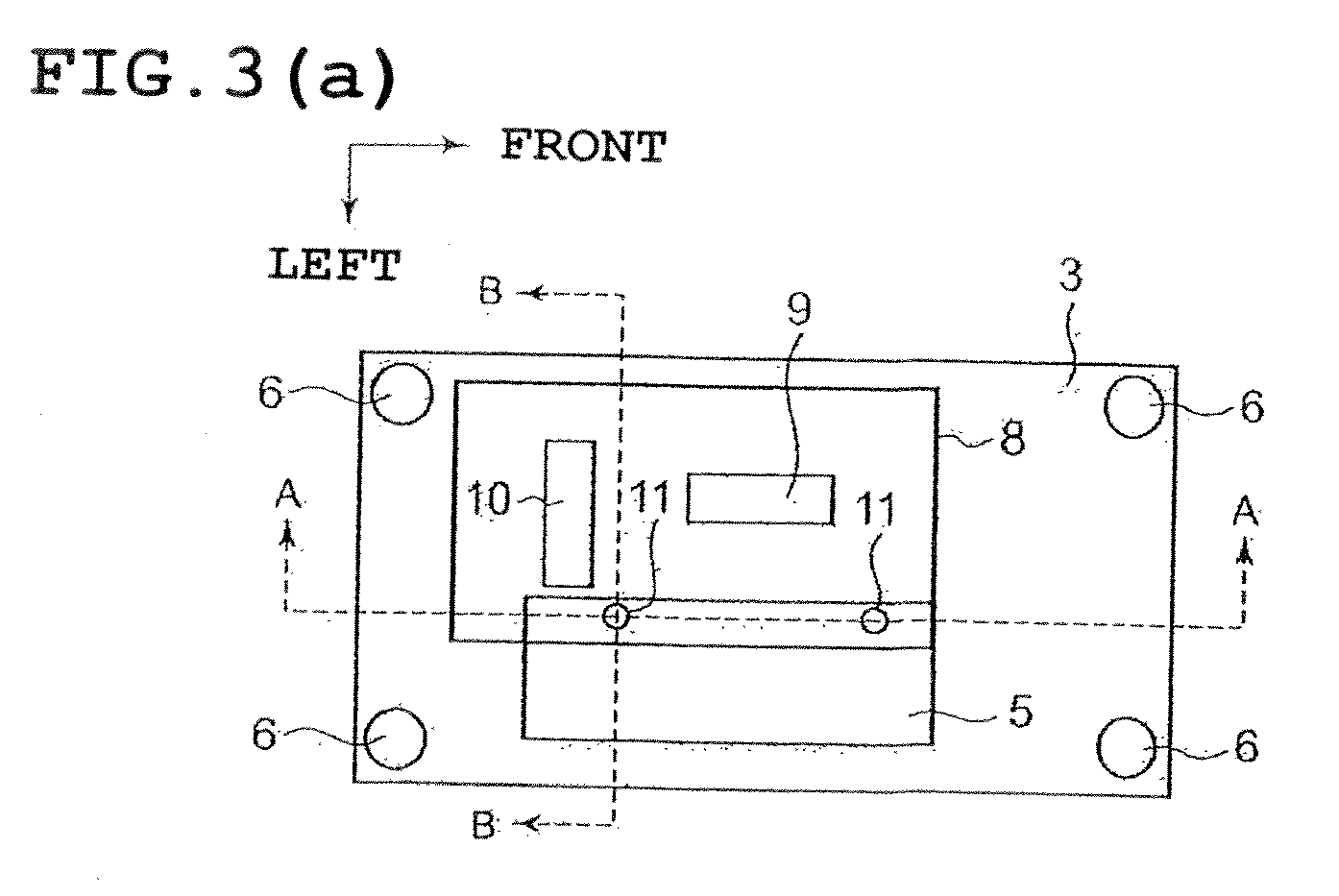
- FIG. 3a is a plan view of first housing 3 according to the embodiment as viewed from an upper side.
- an inside of peripheral wall portion 8 is covered with second housing 4.
- Disposed on the inside of peripheral wall portion 8 are a pair of fixed electrodes 9, 10 and openings 11 (11a, 11b) for a continuity test of fuse 5 that has terminals at both ends thereof.
- the continuity test is carried out by inserting probes into openings 11 and contacting the probes with conductive portions at the both ends of fuse 5. That is, the continuity test can be carried out without removing SDSW 1 from battery pack 2 to thereby expose a whole portion of the fuse outside. Accordingly, a time for performing the test procedure can be reduced.
- openings 11 are disposed on an outside of peripheral wall portion 8, the continuity test can be carried out even in the condition that continuity of the power circuit is allowed. Therefore, safety of a worker of the continuity test can be not always ensured.
- openings 11 cannot be exposed outside unless second housing 4 is detached, it is possible to surely comply with such a maintenance procedure that the continuity test is carried out after continuity of the power circuit must be interrupted. Further, since openings 11 are covered with second housing 4 in the condition that continuity of the power circuit is allowed, entrance of a foreign material such as dust, etc. into battery pack 2 can be prevented even though a dedicated cover is not provided for openings 11.
- fuse 5 is arranged in a plane of projection on which peripheral wall portion 8 is projected in an uncoupling/coupling direction of second housing 4.
- fuse 5 is located in a position close to fixed electrode 9, so that first housing 3 can be reduced in size.
- the continuity test is conducted by inserting probes into openings 11 and contacting the probes to conductive portions at both ends of fuse 5. For this reason, it is necessary to arranged openings 11 and fuse 5 close to each other. Therefore, openings 11 are also arranged close to fixed electrode.
- peripheral wall portion 8 can be reduced in size, and therefore, second housing 4 also can be reduced in size.
- FIG. 3b is a diagram showing arrangement of the pair of fixed electrodes 9, 10 and fuse 5 within first housing 3 according two this embodiment.
- Fuse terminals 17a of fuse 5 is connected with a wire through bolt 12, and then connected with a forward battery.
- One fixed electrode terminal 9 is connected with a wire through conductor 15 and bolt 13, and then connected with a rightward battery.
- the other fixed electrode terminal 10 is connected with fuse terminal 17b through conductor 16 and bolt 14. Accordingly, the continuity test can be carried out by using fixed electrode terminal 10 and opening 11a
- opening 11b for the continuity test is further provided so as to prevent fixed electrode terminals 9, 10 from being used in the continuity test. As a result, it is possible to surely prevent the erroneous test.
- FIG. 4 are diagrams for comparison between an area of first housing 3 and an area of peripheral wall portion 8 in arrangement of the pair of fixed electrodes 9, 10 and fuse 5 in first housing 3.
- the present invention may be embodied as shown in FIGS. 4b and 4c .
- the one fixed electrode 9 is arranged in parallel to fuse 5.
- the other fixed electrodes 10 is arranged to extend in the direction in which makes an angle of 90 degrees with respect to a longitudinal direction of fixed electrode 9, and is arranged to intersect with extension line 18 of the longitudinal direction of fixed electrode 9. With this arrangement, as compared to the arrangement as shown in FIGS.
- FIG. 5 is a bottom view of second housing 4 according to this embodiment when viewed from an underside thereof.
- Second housing 4 includes seal 19 extending along a periphery of second housing 4 which is flitted to first housing 3 when second housing 4 is inserted into first housing 3. Seal 19 seals a clearance between peripheral wall portion 8 of first housing 3 and the periphery of second housing 4. Accordingly, in the condition that continuity of the power circuit is allowed, the pair of fixed electrodes 9, 10 provided in first housing 3 can be made water-proof, and at the same time, openings 11 for the continuity test also can be made water-proof. Accordingly, it is not necessary to take an individual water-proof measure.
- FIG. 6a is a sectional view of first housing 3, taken along lines A-A show in FIG. 3a .
- Fuse terminals 17a, 17b at both ends of the fuse element are connected with a battery harness, etc. and form a circuit.
- Fuse caps 20a, 20b are parts for sealing the fuse element and an arc-extinguishing material in cylindrical fuse cover 21.
- fuse cap 20a on the side of fuse terminal 17a serves as a conductor as a whole including an outer surface thereof.
- the continuity test is carried out by contacting probe 22 inserted through opening 11a with fuse cap 20a.
- FIG. 6b is a sectional view of first housing 3, taken along line B-B shown in FIG. 3a .
- Fuse 5 is located close to fixed electrode terminals 9, 10 as described above, so that openings 11a, 11b for the continuity test can be formed above fuse caps 20a, 20b in an opposed relation to fuse caps 20a, 20b.
- the continuity test can be carried out only by inserting probes 22 into openings 11a, 11b such that probes 22 are placed in an upright position. As a result, it is possible to carry out the continuity test in a stable condition.
- continuity test surface 23 of each of fuse caps 20 which is contacted with probe 22, is contacted with probe 22, as a plane surface.
- probe 22 for the continuity test can be prevented from slipping on continuity test surface 23 so that the continuity test can be carried out in a more stable condition.
- FIG. 7 is a perspective view of peripheral wall portion 8 of first housing 3.
- Cylindrically projecting bosses 24a, 24b are formed in first housing 3 along peripheries of openings 11 for the continuity test. With the provision of bosses 24a, 24b, the positions of openings 11 can be readily recognized, and it is not necessary to use fixed electrode terminals 9, 10 in the continuity test. As a result, an erroneous test can be prevented.
- raised bosses 24a, 24b serve as guides, thereby facilitating contacting probes 22 for the continuity test to continuity test surface 23 and carrying out the continuity test in a stable condition.
- FIG. 8a is a plan view of dedicated cap 25 to be mounted to peripheral wall portion 8, when viewed from an upper side of dedicated cap 25.
- FIG. 8b is a sectional view of dedicated cap 25 when viewed from a lateral side thereof.
- a pair of holes 26 for the continuity test are formed in dedicated cap 25 corresponding to the pair of openings 11 for the continuity test.
- dedicated cap 25 In such a state that dedicated cap 25 is coupled to peripheral wall portion 8, fixed electrode terminals 9, 10 are covered with dedicated cap 25, and only holes 26 are exposed, so that fixed electrode terminals 9, 10 cannot be used in the continuity test. Further, holes 26 in dedicated cap 25 each serve as a guide that guides probe 22 for the continuity test. Therefore, probes 22 can be raised at a predetermined angle relative to the continuity test surface so that the continuity test can be carried out in a stable condition.
- seal 19 is provided in second housing 4, seal 19 may be provided on the side of peripheral wall portion 8. Even in such a case, same effects as those in the above-described embodiment can be obtained.
- the seal in a case where SDSW 1 is arranged in a position in which SDSW 1 is prevented from contacting with water, the seal can be omitted.
- peripheral wall portion 8 can be provided with a vent hole that has such a size as to prevent insertion of probe 22.
Landscapes
- Engineering & Computer Science (AREA)
- Power Engineering (AREA)
- Fuses (AREA)
- Connection Of Batteries Or Terminals (AREA)
Abstract
Description
- The present invention relates to a power circuit interrupting device that electrically connects and disconnects a power circuit of a hybrid motor vehicle, an electric motor vehicle, etc.
- Upon carrying out a maintenance work of a hybrid motor vesicle, an electric motor vehicle, etc., a power circuit must be brought into interruption by a manual operation in order to ensure safe of a maintenance worker. Such a power circuit interrupting device as described in the following
Patent Literature 1 is known.
The device as described inPatent Literature 1 includes a pair of fixed electrodes and a fuse which are disposed in a casing, a moveable electrode capable of being coupled to the fixed electrodes to establish electrical connection between the fixed electrodes and being uncoupled from the fixed electrodes to interrupt the electrical connection therebetween, and a coupling/uncoupling operation handle provided with the moveable electrode. The device is constructed such that a conduction path is accommodated within the casing when an electrical continuity is established, and therefore, the device is excellent in view of safety. - However, in the device described in the
Patent Literature 1, the fuse is disposed within the casing. Due to this construction, in order to carry out a continuity test for the fuse, it is necessary to uncouple the moveable electrode from the fixed electrodes, loosen screws, and open the casing to thereby expose the fuse outside. Accordingly, it takes a long time for performing the test procedure. - Patent Literature 1: Japanese Patent Application Unexamined Publication No.
9-265874 - A power circuit interrupting device according the present invention includes a first housing including a pair of fixed electrodes and a fuse, and a second housing including a moveable electrode, the moveable electrode interrupting electrical connection between the fixed electrodes when the second housing is uncoupled from the first housing, and establishing the electrical connection between the fixed electrodes when the second housing is coupled with the first housing. The first housing has an opening provided for carrying out a continuity test for the fuse. The opening is covered with the second housing in a condition that continuity of a circuit is allowed.
- In the device according to the present invention, it is possible to carry out a continuity test for the fuse without exposing a whole portion of the fuse. Therefore, the device can serve to reduce a time for performing the test procedure. Further, in order to carry out the continuity test, the second housing having the moveable electrode must be uncoupled from the first housing, whereby the device can serve to keep safety. In addition, since the opening for the continuity test is covered with the second housing in a normal condition in which continuity of the power circuit is allowed, a foreign material such as dust can be prevented from entering into the device.
-
-
FIG. 1 is a circuit diagram showing a part of a power circuit including a power circuit interrupting device (SDSW) according to an embodiment of the present invention. -
FIG. 2(a) is a perspective view of a whole construction of the SDSW according to the embodiment, andFIG. 2(b) is a front view thereof. -
FIG. 3(a) is a plan view of a first housing according to the embodiment, andFIG. 3(b) is an explanatory diagram showing arrangement of a fuse and fixed electrodes within the first housing. -
FIG. 4 are explanatory diagrams showing examples of arrangement, of a pair of fixed electrodes and a fuse within the first housing. -
FIG. 5 is a bottom view of a second housing according to the embodiment. -
FIG. 6(a) is a sectional view as viewed from a left side of the SDSW according to the embodiment, andFIG. 6 (b) is a sectional view as viewed from a front side of the SDSW according to the embodiment. -
FIG. 7 is a perspective view showing bosses disposed along a periphery of an opening of the first housing. -
FIG. 8(a) is a plan view of a dedicated cap for a continuity test, andFIG. 8(b) is a sectional view of the dedicated cap as viewed from a left side thereof. - In the following, an embodiment of the present invention is explained by referring to
FIG. 1 to FIG. 8 .FIG. 1 is an electric circuit diagram showing a part of a power circuit of a hybrid vehicle, an electric vehicle, etc. Service disconnect switch (hereinafter referred to as simply "SDSW") 1 is a power circuit interrupting device according to the present invention. SDSW 1 serves as a breaker device that constitutes a part ofbattery pack 2 and is disposed in a power circuit to interrupt or establish electrical connection between batteries, and can interrupt continuity of the power circuit including a fuse.
SDSW 1 includesfirst housing 3 including a pair of fixed electrodes andfuse 5, andsecond housing 4 including a moveable electrode that is uncoupled from the fixed electrodes to disconnect the fixed electrodes from each other or coupled with the fixed electrodes to connect the fixed electrodes with each other. A work of a continuity test can be safely performed by interrupting the electrical connection between batteries by uncoupling the moveable electrode from the fixed electrodes throughsecond housing 4 or establishing the electrical connection between batteries by coupling the moveable electrode with the fixed electrodes throughsecond housing 4.
In a condition that continuity of the circuit is allowed, electric currant from the batteries flows to an inverter and a DC/DC converter through a main relay. -
FIG. 2a is a perspective view of SDSW 1 as a whole according to the embodiment. SDSW 1 is fixed tobattery pack 2 through bolts inserted intobolt holes 6 which are formed at four corners offirst housing 3. Thus, SDSW 1 is formed integrally withbattery pack 2, and configured to a box shape. In SDSW 1, whensecond housing 4 is coupled toperipheral wall portion 8 that projects outwardly from a base portion offirst housing 3, the electrodes offirst housing 3 and the electrode ofsecond housing 4 are connected with each other to thereby allow continuity of the power circuit. -
FIG. 2b is a front view of SDSW 1 as viewed from a forward direction. Seal 7 is provided in a connecting portion betweenSDSW 1 andbattery pack 2, and prevents a foreign material such as dust, water, etc. from entering intobattery pack 2.Fuse 5 is arranged within a box-shaped space formed by SDSW 1 andbattery pack 2. -
FIG. 3a is a plan view offirst housing 3 according to the embodiment as viewed from an upper side. In a condition that continuity of the power circuit is allowed, an inside ofperipheral wall portion 8 is covered withsecond housing 4. Disposed on the inside ofperipheral wall portion 8 are a pair offixed electrodes fuse 5 that has terminals at both ends thereof. The continuity test is carried out by inserting probes intoopenings 11 and contacting the probes with conductive portions at the both ends offuse 5. That is, the continuity test can be carried out without removingSDSW 1 frombattery pack 2 to thereby expose a whole portion of the fuse outside. Accordingly, a time for performing the test procedure can be reduced.
Ifopenings 11 are disposed on an outside ofperipheral wall portion 8, the continuity test can be carried out even in the condition that continuity of the power circuit is allowed. Therefore, safety of a worker of the continuity test can be not always ensured. In this embodiment, sinceopenings 11 cannot be exposed outside unlesssecond housing 4 is detached, it is possible to surely comply with such a maintenance procedure that the continuity test is carried out after continuity of the power circuit must be interrupted.
Further, sinceopenings 11 are covered withsecond housing 4 in the condition that continuity of the power circuit is allowed, entrance of a foreign material such as dust, etc. intobattery pack 2 can be prevented even though a dedicated cover is not provided foropenings 11. - As shown in
FIG. 3a , at least a part offuse 5 is arranged in a plane of projection on whichperipheral wall portion 8 is projected in an uncoupling/coupling direction ofsecond housing 4. With this arrangement,fuse 5 is located in a position close to fixedelectrode 9, so thatfirst housing 3 can be reduced in size. Further, the continuity test is conducted by inserting probes intoopenings 11 and contacting the probes to conductive portions at both ends offuse 5. For this reason, it is necessary to arrangedopenings 11 and fuse 5 close to each other. Therefore,openings 11 are also arranged close to fixed electrode. As a result,peripheral wall portion 8 can be reduced in size, and therefore,second housing 4 also can be reduced in size. -
FIG. 3b is a diagram showing arrangement of the pair of fixedelectrodes fuse 5 withinfirst housing 3 according two this embodiment.Fuse terminals 17a offuse 5 is connected with a wire throughbolt 12, and then connected with a forward battery. One fixedelectrode terminal 9 is connected with a wire throughconductor 15 andbolt 13, and then connected with a rightward battery. The other fixedelectrode terminal 10 is connected withfuse terminal 17b throughconductor 16 andbolt 14. Accordingly, the continuity test can be carried out by using fixedelectrode terminal 10 andopening 11a However, since fixedelectrode terminal 9 and fixedelectrode terminal 10 are not distinguishable in appearance from each other, there is a possibility of carrying out an erroneous test using fixedelectrode terminal 9 andopening 11a. In order to solve this problem, in this embodiment, opening 11b for the continuity test is further provided so as to prevent fixedelectrode terminals -
FIG. 4 are diagrams for comparison between an area offirst housing 3 and an area ofperipheral wall portion 8 in arrangement of the pair of fixedelectrodes fuse 5 infirst housing 3.
In a case where fixed electrodes each having an elongated shape are used, the present invention may be embodied as shown inFIGS. 4b and 4c . In contrast, in the above-described embodiment, as shown inFIG. 4a , the one fixedelectrode 9 is arranged in parallel to fuse 5. The otherfixed electrodes 10 is arranged to extend in the direction in which makes an angle of 90 degrees with respect to a longitudinal direction of fixedelectrode 9, and is arranged to intersect withextension line 18 of the longitudinal direction of fixedelectrode 9. With this arrangement, as compared to the arrangement as shown inFIGS. 4b and 4c , even though a distance x betweenfuse 5 and the one fixedelectrode 9 is same, the pair of fixedelectrodes fuse 5 can be arranged in a minimum area, thereby reducing the size offirst housing 3. Further, since the continuity test is carried out by inserting probes intoopenings 11 and contacting the probes with the conductive portions at both ends offuse 5,openings 11 andfuse 5 must be located close to each other so that the pair of fixedelectrodes openings 11 can be arranged in a minimum area. Accordingly, it is possible to reduce not onlyperipheral wall portion 8 but alsosecond housing 4 in size. -
FIG. 5 is a bottom view ofsecond housing 4 according to this embodiment when viewed from an underside thereof. Disposed withinsecond housing 4 aremoveable electrodes 18 that have shapes corresponding to those of the pair of fixedelectrodes first housing 3.Second housing 4 includesseal 19 extending along a periphery ofsecond housing 4 which is flitted tofirst housing 3 whensecond housing 4 is inserted intofirst housing 3.Seal 19 seals a clearance betweenperipheral wall portion 8 offirst housing 3 and the periphery ofsecond housing 4. Accordingly, in the condition that continuity of the power circuit is allowed, the pair of fixedelectrodes first housing 3 can be made water-proof, and at the same time,openings 11 for the continuity test also can be made water-proof. Accordingly, it is not necessary to take an individual water-proof measure. -
FIG. 6a is a sectional view offirst housing 3, taken along lines A-A show inFIG. 3a .Fuse terminals cylindrical fuse cover 21.
In this embodiment,fuse cap 20a on the side offuse terminal 17a serves as a conductor as a whole including an outer surface thereof. The continuity test is carried out by contactingprobe 22 inserted throughopening 11a withfuse cap 20a. When not fuse terminal 17a butfuse cap 20a is thus utilized in the continuity test, a distance y betweenfuse cap 20a and fuse terminal 17b electrically connected to fixedelectrode terminal 10 is shorter than a distance z betweenfuse terminal 17a and fuse terminal 17b electrically connected to fixedelectrode terminal 10. therefore, it is possible to locateopening 11a closer to fixedelectrode 10. Accordingly,peripheral wall portion 8 can be reduced in size, and therefore,second housing 4 can be reduced in size.
Further, in a case where only onefuse cap 20a of the pair of fuse caps 20 is formed as a conductor, there is a possibility that fuse 5 is connected in a reverse direction upon assembling the apparatus and thereby the continuity test cannot be carried out. To avoid such a problem, in this embodiment, fuse cap 20b on the side offuse terminal 17b is also formed as a conductor, andopening 11b associated with fuse cap 20b is provided. -
FIG. 6b is a sectional view offirst housing 3, taken along line B-B shown inFIG. 3a .Fuse 5 is located close to fixedelectrode terminals openings fuse caps 20a, 20b in an opposed relation to fusecaps 20a, 20b. With this construction, the continuity test can be carried out only by insertingprobes 22 intoopenings
As a result, it is possible to carry out the continuity test in a stable condition. - As shown in
FIG. 6b , it is desirable to formcontinuity test surface 23 of each of fuse caps 20 which is contacted withprobe 22, as a plane surface. By thus formingcontinuity test surface 23 as a plane surface, probe 22 for the continuity test can be prevented from slipping oncontinuity test surface 23 so that the continuity test can be carried out in a more stable condition. -
FIG. 7 is a perspective view ofperipheral wall portion 8 offirst housing 3.Cylindrically projecting bosses first housing 3 along peripheries ofopenings 11 for the continuity test. With the provision ofbosses openings 11 can be readily recognized, and it is not necessary to use fixedelectrode terminals bosses probes 22 for the continuity test tocontinuity test surface 23 and carrying out the continuity test in a stable condition. - Although in the above-described embodiment, the procedure of carrying out the continuity test in such a state that
second housing 4 is detached to expose fixedelectrode terminals dedicated cap 25 capable of being inserted intoperipheral wall portion 8 after detachingsecond housing 4 may be used in order to completely prohibit use of fixedelectrode terminals FIG. 8a is a plan view ofdedicated cap 25 to be mounted toperipheral wall portion 8, when viewed from an upper side ofdedicated cap 25.FIG. 8b is a sectional view ofdedicated cap 25 when viewed from a lateral side thereof. A pair ofholes 26 for the continuity test are formed indedicated cap 25 corresponding to the pair ofopenings 11 for the continuity test. In such a state thatdedicated cap 25 is coupled toperipheral wall portion 8, fixedelectrode terminals dedicated cap 25, and only holes 26 are exposed, so that fixedelectrode terminals dedicated cap 25 each serve as a guide that guidesprobe 22 for the continuity test. Therefore, probes 22 can be raised at a predetermined angle relative to the continuity test surface so that the continuity test can be carried out in a stable condition. - Further, although in the above-described embodiment, seal 19 is provided in
second housing 4, seal 19 may be provided on the side ofperipheral wall portion 8. Even in such a case, same effects as those in the above-described embodiment can be obtained.
In addition, in a case whereSDSW 1 is arranged in a position in whichSDSW 1 is prevented from contacting with water, the seal can be omitted. Further,peripheral wall portion 8 can be provided with a vent hole that has such a size as to prevent insertion ofprobe 22.
Claims (7)
- A power circuit interrupting device comprising:a first housing including a pair of fixed electrodes and a fuse; anda second housing including a moveable electrode, the moveable electrode interrupting electrical connection between the fixed electrodes when the second housing is uncoupled from the first housing, and establishing the electrical connection between the fixed electrodes when the second housing is coupled with the first housing,wherein the first housing has an opening provided for carrying out a continuity test for the fuse, the opening being covered with the second housing in a condition that continuity of a circuit is allowed.
- The power circuit interrupting device as claimed in claim 1, wherein at least a part of the fuse is arranged in a plane of projection on which an area covered with the second housing is projected in an uncoupling/coupling direction of the second housing.
- The power circuit interrupting device as claimed in claim 1, wherein the fuse comprises fuse terminals disposed at both ends of the fuse, and fuse caps each having a surface electrically connected with the fuse terminals, the fuse caps being disposed on both end portions of a fuse cover.
- The power circuit interrupting device as claimed in claim 1, wherein the fuse comprises fuse terminals disposed at both ends of the fuse, and the fixed electrodes are constituted of a pair of elongated terminals, one of the pair of fixed electrode terminals being arranged parallel to the fuse, the other of the pair of fixed electrode terminals being arranged to intersect with an extension line of the one of the pair of fixed electrode terminals.
- The power circuit interrupting device as claimed in claim 3, wherein the fuse cap has a plane surface portion opposed to the opening for the continuity test.
- The power circuit interrupting device as claimed in claim 1, wherein the opening for the continuity test is constituted of two openings formed corresponding to a pair of continuity test portions of the fuse.
- The power circuit interrupting device as claimed in claim 1, wherein a periphery of the opening is raised.
Applications Claiming Priority (2)
| Application Number | Priority Date | Filing Date | Title |
|---|---|---|---|
| JP2010260694 | 2010-11-23 | ||
| PCT/JP2011/072982 WO2012070318A1 (en) | 2010-11-23 | 2011-10-05 | Power circuit interrupting device |
Publications (3)
| Publication Number | Publication Date |
|---|---|
| EP2645394A1 true EP2645394A1 (en) | 2013-10-02 |
| EP2645394A4 EP2645394A4 (en) | 2015-04-15 |
| EP2645394B1 EP2645394B1 (en) | 2016-02-03 |
Family
ID=46145676
Family Applications (1)
| Application Number | Title | Priority Date | Filing Date |
|---|---|---|---|
| EP11843693.0A Not-in-force EP2645394B1 (en) | 2010-11-23 | 2011-10-05 | Power circuit interrupting device |
Country Status (10)
| Country | Link |
|---|---|
| US (1) | US9773631B2 (en) |
| EP (1) | EP2645394B1 (en) |
| JP (1) | JP5459413B2 (en) |
| KR (1) | KR101464455B1 (en) |
| CN (1) | CN103229265B (en) |
| BR (1) | BR112013009976A2 (en) |
| MX (1) | MX2013004046A (en) |
| MY (1) | MY161783A (en) |
| RU (1) | RU2534031C1 (en) |
| WO (1) | WO2012070318A1 (en) |
Families Citing this family (1)
| Publication number | Priority date | Publication date | Assignee | Title |
|---|---|---|---|---|
| FR3030872B1 (en) * | 2014-12-22 | 2016-12-09 | Renault Sa | FUSE HOUSING FOR MOTOR VEHICLE. |
Family Cites Families (28)
| Publication number | Priority date | Publication date | Assignee | Title |
|---|---|---|---|---|
| US4067103A (en) * | 1977-02-07 | 1978-01-10 | Littelfuse, Inc. | Method of making a plug-in fuse |
| US4344060A (en) * | 1980-09-19 | 1982-08-10 | Littelfuse, Inc. | Enclosed plug-in fuse assembly |
| DE3639669C2 (en) * | 1986-11-20 | 1993-12-23 | Efen Elektrotech Fab | Low-voltage, high-performance fuse switchgear with window arrangement |
| JPH0555721U (en) | 1991-12-26 | 1993-07-23 | 古河電気工業株式会社 | Electrical junction box |
| KR960008219Y1 (en) * | 1991-12-26 | 1996-09-24 | 현대자동차 주식회사 | Small fuse with burnout terminal |
| CN2153874Y (en) * | 1993-05-20 | 1994-01-19 | 廖南辉 | Safe Connecting Plug |
| JP3435973B2 (en) | 1996-03-29 | 2003-08-11 | 住友電装株式会社 | Breaker device |
| US5842560A (en) | 1996-02-15 | 1998-12-01 | Sumitomo Wiring Systems, Ltd. | Breaker device |
| US5847338A (en) | 1996-02-15 | 1998-12-08 | Sumitomo Wiring Systems, Ltd. | Breaker device |
| JPH1083753A (en) | 1996-09-05 | 1998-03-31 | Yazaki Corp | Service plug |
| DE29721446U1 (en) | 1997-12-04 | 1998-04-30 | Wöhner GmbH & Co. KG Elektrotechnische Systeme, 96472 Rödental | Viewing window |
| EP0983596A1 (en) * | 1997-12-29 | 2000-03-08 | The Siemon Company | Current and transient voltage protector |
| US6054915A (en) * | 1998-02-17 | 2000-04-25 | Cooper Industries, Inc. | Compact touchsafe fuseholder with removable fuse carrier |
| JP3514290B2 (en) * | 1998-09-04 | 2004-03-31 | 矢崎総業株式会社 | Circuit breaker |
| JP3566573B2 (en) * | 1999-03-01 | 2004-09-15 | 矢崎総業株式会社 | Power shut-off device |
| US6157287A (en) * | 1999-03-03 | 2000-12-05 | Cooper Technologies Company | Touch safe fuse module and holder |
| JP2000311576A (en) * | 1999-04-27 | 2000-11-07 | Yazaki Corp | Power cut-off device |
| JP3612439B2 (en) * | 1999-05-06 | 2005-01-19 | 矢崎総業株式会社 | Power shut-off device |
| JP2001057134A (en) * | 1999-08-18 | 2001-02-27 | Auto Network Gijutsu Kenkyusho:Kk | Breaker device |
| JP3583033B2 (en) * | 1999-08-19 | 2004-10-27 | 株式会社オートネットワーク技術研究所 | Breaker device |
| JP3657160B2 (en) * | 1999-08-18 | 2005-06-08 | 株式会社オートネットワーク技術研究所 | Breaker device |
| US6407656B1 (en) | 1999-08-18 | 2002-06-18 | Autonetworks Technologies, Ltd. | Breaker device |
| JP4272037B2 (en) * | 2003-11-10 | 2009-06-03 | 矢崎総業株式会社 | Lever fitting type power circuit breaker |
| DE102006016557A1 (en) * | 2006-04-07 | 2007-10-11 | Air Liquide Deutschland Gmbh | Refrigerated vehicle with external cooling module and cooling method |
| JP5014012B2 (en) * | 2007-07-31 | 2012-08-29 | 矢崎総業株式会社 | Power circuit breaker |
| US8937524B2 (en) * | 2009-03-25 | 2015-01-20 | Littelfuse, Inc. | Solderless surface mount fuse |
| RU90276U1 (en) | 2009-04-20 | 2009-12-27 | Государственное образовательное учреждение высшего профессионального образования "Петербургский государственный университет путей сообщения" | PROTECTIVE-REGULATING KIT FOR CONTROLLING THE WORK OF THE WAGON GENERATOR |
| CN201402824Y (en) * | 2009-05-07 | 2010-02-10 | 光阳工业股份有限公司 | Battery box device for electric vehicles |
-
2011
- 2011-10-05 CN CN201180056382.4A patent/CN103229265B/en not_active Expired - Fee Related
- 2011-10-05 MY MYPI2013001877A patent/MY161783A/en unknown
- 2011-10-05 WO PCT/JP2011/072982 patent/WO2012070318A1/en not_active Ceased
- 2011-10-05 JP JP2012545648A patent/JP5459413B2/en not_active Expired - Fee Related
- 2011-10-05 RU RU2013128492/07A patent/RU2534031C1/en not_active IP Right Cessation
- 2011-10-05 EP EP11843693.0A patent/EP2645394B1/en not_active Not-in-force
- 2011-10-05 US US13/988,686 patent/US9773631B2/en not_active Expired - Fee Related
- 2011-10-05 BR BR112013009976A patent/BR112013009976A2/en not_active IP Right Cessation
- 2011-10-05 KR KR1020137012988A patent/KR101464455B1/en not_active Expired - Fee Related
- 2011-10-05 MX MX2013004046A patent/MX2013004046A/en active IP Right Grant
Non-Patent Citations (2)
| Title |
|---|
| No further relevant documents disclosed * |
| See also references of WO2012070318A1 * |
Also Published As
| Publication number | Publication date |
|---|---|
| MX2013004046A (en) | 2013-06-28 |
| EP2645394A4 (en) | 2015-04-15 |
| CN103229265A (en) | 2013-07-31 |
| JP5459413B2 (en) | 2014-04-02 |
| KR20130103558A (en) | 2013-09-23 |
| EP2645394B1 (en) | 2016-02-03 |
| CN103229265B (en) | 2015-08-26 |
| WO2012070318A1 (en) | 2012-05-31 |
| KR101464455B1 (en) | 2014-11-21 |
| US20130241687A1 (en) | 2013-09-19 |
| BR112013009976A2 (en) | 2016-08-02 |
| RU2534031C1 (en) | 2014-11-27 |
| MY161783A (en) | 2017-05-15 |
| JPWO2012070318A1 (en) | 2014-05-19 |
| US9773631B2 (en) | 2017-09-26 |
Similar Documents
| Publication | Publication Date | Title |
|---|---|---|
| CN105027364B (en) | Manual service disconnects for battery systems | |
| JP7101741B2 (en) | Power connector system | |
| JP5779010B2 (en) | Bus bar module structure | |
| KR20150118338A (en) | Service Plug Unit, Device Unit And Power Disconnecting System For Electric Automobile Having The Same | |
| KR20150107377A (en) | High voltage male type connector | |
| JPH09147734A (en) | Fuse box | |
| JP2013226019A (en) | Electric junction box | |
| JP2014049376A (en) | Connector connecting structure | |
| KR102662704B1 (en) | Manual Service Disconnect for Battery System | |
| KR20150026861A (en) | Circuit interrupter apparatus | |
| KR20190057883A (en) | Junction Block | |
| JP2000082548A (en) | Circuit breaker | |
| CN117458090A (en) | Wireless beam battery pack breaking unit | |
| EP2645394B1 (en) | Power circuit interrupting device | |
| CN115668657A (en) | Terminal block | |
| CN112710960B (en) | Integrated MSD connector test box for power battery test | |
| US11476060B1 (en) | Manual service disconnect for in-vehicle electric current | |
| CN210954278U (en) | Integrated MSD connector test box for testing power battery | |
| CN218123768U (en) | Connector with a locking member | |
| CN220963192U (en) | Leakage circuit breaker | |
| KR20230170509A (en) | Interlock device of power relay box | |
| KR20070006071A (en) | Car battery | |
| CN118841776A (en) | Integrated fuse type high-voltage connector | |
| JP2014026888A (en) | Connector |
Legal Events
| Date | Code | Title | Description |
|---|---|---|---|
| PUAI | Public reference made under article 153(3) epc to a published international application that has entered the european phase |
Free format text: ORIGINAL CODE: 0009012 |
|
| 17P | Request for examination filed |
Effective date: 20130620 |
|
| AK | Designated contracting states |
Kind code of ref document: A1 Designated state(s): AL AT BE BG CH CY CZ DE DK EE ES FI FR GB GR HR HU IE IS IT LI LT LU LV MC MK MT NL NO PL PT RO RS SE SI SK SM TR |
|
| DAX | Request for extension of the european patent (deleted) | ||
| RA4 | Supplementary search report drawn up and despatched (corrected) |
Effective date: 20150318 |
|
| RIC1 | Information provided on ipc code assigned before grant |
Ipc: H01H 31/24 20060101AFI20150312BHEP Ipc: H01H 85/02 20060101ALI20150312BHEP |
|
| GRAP | Despatch of communication of intention to grant a patent |
Free format text: ORIGINAL CODE: EPIDOSNIGR1 |
|
| INTG | Intention to grant announced |
Effective date: 20151019 |
|
| RIN1 | Information on inventor provided before grant (corrected) |
Inventor name: ISHIZAKI, SHIN |
|
| GRAS | Grant fee paid |
Free format text: ORIGINAL CODE: EPIDOSNIGR3 |
|
| GRAA | (expected) grant |
Free format text: ORIGINAL CODE: 0009210 |
|
| AK | Designated contracting states |
Kind code of ref document: B1 Designated state(s): AL AT BE BG CH CY CZ DE DK EE ES FI FR GB GR HR HU IE IS IT LI LT LU LV MC MK MT NL NO PL PT RO RS SE SI SK SM TR |
|
| REG | Reference to a national code |
Ref country code: GB Ref legal event code: FG4D |
|
| REG | Reference to a national code |
Ref country code: AT Ref legal event code: REF Ref document number: 774039 Country of ref document: AT Kind code of ref document: T Effective date: 20160215 Ref country code: CH Ref legal event code: EP |
|
| REG | Reference to a national code |
Ref country code: IE Ref legal event code: FG4D |
|
| REG | Reference to a national code |
Ref country code: DE Ref legal event code: R096 Ref document number: 602011023135 Country of ref document: DE |
|
| REG | Reference to a national code |
Ref country code: LT Ref legal event code: MG4D Ref country code: NL Ref legal event code: MP Effective date: 20160203 |
|
| REG | Reference to a national code |
Ref country code: AT Ref legal event code: MK05 Ref document number: 774039 Country of ref document: AT Kind code of ref document: T Effective date: 20160203 |
|
| PG25 | Lapsed in a contracting state [announced via postgrant information from national office to epo] |
Ref country code: ES Free format text: LAPSE BECAUSE OF FAILURE TO SUBMIT A TRANSLATION OF THE DESCRIPTION OR TO PAY THE FEE WITHIN THE PRESCRIBED TIME-LIMIT Effective date: 20160203 Ref country code: GR Free format text: LAPSE BECAUSE OF FAILURE TO SUBMIT A TRANSLATION OF THE DESCRIPTION OR TO PAY THE FEE WITHIN THE PRESCRIBED TIME-LIMIT Effective date: 20160504 Ref country code: IT Free format text: LAPSE BECAUSE OF FAILURE TO SUBMIT A TRANSLATION OF THE DESCRIPTION OR TO PAY THE FEE WITHIN THE PRESCRIBED TIME-LIMIT Effective date: 20160203 Ref country code: NO Free format text: LAPSE BECAUSE OF FAILURE TO SUBMIT A TRANSLATION OF THE DESCRIPTION OR TO PAY THE FEE WITHIN THE PRESCRIBED TIME-LIMIT Effective date: 20160503 Ref country code: HR Free format text: LAPSE BECAUSE OF FAILURE TO SUBMIT A TRANSLATION OF THE DESCRIPTION OR TO PAY THE FEE WITHIN THE PRESCRIBED TIME-LIMIT Effective date: 20160203 Ref country code: FI Free format text: LAPSE BECAUSE OF FAILURE TO SUBMIT A TRANSLATION OF THE DESCRIPTION OR TO PAY THE FEE WITHIN THE PRESCRIBED TIME-LIMIT Effective date: 20160203 |
|
| PG25 | Lapsed in a contracting state [announced via postgrant information from national office to epo] |
Ref country code: LT Free format text: LAPSE BECAUSE OF FAILURE TO SUBMIT A TRANSLATION OF THE DESCRIPTION OR TO PAY THE FEE WITHIN THE PRESCRIBED TIME-LIMIT Effective date: 20160203 Ref country code: AT Free format text: LAPSE BECAUSE OF FAILURE TO SUBMIT A TRANSLATION OF THE DESCRIPTION OR TO PAY THE FEE WITHIN THE PRESCRIBED TIME-LIMIT Effective date: 20160203 Ref country code: PL Free format text: LAPSE BECAUSE OF FAILURE TO SUBMIT A TRANSLATION OF THE DESCRIPTION OR TO PAY THE FEE WITHIN THE PRESCRIBED TIME-LIMIT Effective date: 20160203 Ref country code: PT Free format text: LAPSE BECAUSE OF FAILURE TO SUBMIT A TRANSLATION OF THE DESCRIPTION OR TO PAY THE FEE WITHIN THE PRESCRIBED TIME-LIMIT Effective date: 20160603 Ref country code: RS Free format text: LAPSE BECAUSE OF FAILURE TO SUBMIT A TRANSLATION OF THE DESCRIPTION OR TO PAY THE FEE WITHIN THE PRESCRIBED TIME-LIMIT Effective date: 20160203 Ref country code: IS Free format text: LAPSE BECAUSE OF FAILURE TO SUBMIT A TRANSLATION OF THE DESCRIPTION OR TO PAY THE FEE WITHIN THE PRESCRIBED TIME-LIMIT Effective date: 20160603 Ref country code: NL Free format text: LAPSE BECAUSE OF FAILURE TO SUBMIT A TRANSLATION OF THE DESCRIPTION OR TO PAY THE FEE WITHIN THE PRESCRIBED TIME-LIMIT Effective date: 20160203 Ref country code: LV Free format text: LAPSE BECAUSE OF FAILURE TO SUBMIT A TRANSLATION OF THE DESCRIPTION OR TO PAY THE FEE WITHIN THE PRESCRIBED TIME-LIMIT Effective date: 20160203 Ref country code: SE Free format text: LAPSE BECAUSE OF FAILURE TO SUBMIT A TRANSLATION OF THE DESCRIPTION OR TO PAY THE FEE WITHIN THE PRESCRIBED TIME-LIMIT Effective date: 20160203 |
|
| REG | Reference to a national code |
Ref country code: FR Ref legal event code: PLFP Year of fee payment: 6 |
|
| PG25 | Lapsed in a contracting state [announced via postgrant information from national office to epo] |
Ref country code: EE Free format text: LAPSE BECAUSE OF FAILURE TO SUBMIT A TRANSLATION OF THE DESCRIPTION OR TO PAY THE FEE WITHIN THE PRESCRIBED TIME-LIMIT Effective date: 20160203 Ref country code: DK Free format text: LAPSE BECAUSE OF FAILURE TO SUBMIT A TRANSLATION OF THE DESCRIPTION OR TO PAY THE FEE WITHIN THE PRESCRIBED TIME-LIMIT Effective date: 20160203 |
|
| REG | Reference to a national code |
Ref country code: DE Ref legal event code: R097 Ref document number: 602011023135 Country of ref document: DE |
|
| PG25 | Lapsed in a contracting state [announced via postgrant information from national office to epo] |
Ref country code: SM Free format text: LAPSE BECAUSE OF FAILURE TO SUBMIT A TRANSLATION OF THE DESCRIPTION OR TO PAY THE FEE WITHIN THE PRESCRIBED TIME-LIMIT Effective date: 20160203 Ref country code: RO Free format text: LAPSE BECAUSE OF FAILURE TO SUBMIT A TRANSLATION OF THE DESCRIPTION OR TO PAY THE FEE WITHIN THE PRESCRIBED TIME-LIMIT Effective date: 20160203 Ref country code: CZ Free format text: LAPSE BECAUSE OF FAILURE TO SUBMIT A TRANSLATION OF THE DESCRIPTION OR TO PAY THE FEE WITHIN THE PRESCRIBED TIME-LIMIT Effective date: 20160203 Ref country code: SK Free format text: LAPSE BECAUSE OF FAILURE TO SUBMIT A TRANSLATION OF THE DESCRIPTION OR TO PAY THE FEE WITHIN THE PRESCRIBED TIME-LIMIT Effective date: 20160203 |
|
| PLBE | No opposition filed within time limit |
Free format text: ORIGINAL CODE: 0009261 |
|
| STAA | Information on the status of an ep patent application or granted ep patent |
Free format text: STATUS: NO OPPOSITION FILED WITHIN TIME LIMIT |
|
| PG25 | Lapsed in a contracting state [announced via postgrant information from national office to epo] |
Ref country code: BE Free format text: LAPSE BECAUSE OF FAILURE TO SUBMIT A TRANSLATION OF THE DESCRIPTION OR TO PAY THE FEE WITHIN THE PRESCRIBED TIME-LIMIT Effective date: 20160203 |
|
| 26N | No opposition filed |
Effective date: 20161104 |
|
| PG25 | Lapsed in a contracting state [announced via postgrant information from national office to epo] |
Ref country code: SI Free format text: LAPSE BECAUSE OF FAILURE TO SUBMIT A TRANSLATION OF THE DESCRIPTION OR TO PAY THE FEE WITHIN THE PRESCRIBED TIME-LIMIT Effective date: 20160203 Ref country code: BG Free format text: LAPSE BECAUSE OF FAILURE TO SUBMIT A TRANSLATION OF THE DESCRIPTION OR TO PAY THE FEE WITHIN THE PRESCRIBED TIME-LIMIT Effective date: 20160503 |
|
| REG | Reference to a national code |
Ref country code: CH Ref legal event code: PL |
|
| REG | Reference to a national code |
Ref country code: IE Ref legal event code: MM4A |
|
| PG25 | Lapsed in a contracting state [announced via postgrant information from national office to epo] |
Ref country code: LI Free format text: LAPSE BECAUSE OF NON-PAYMENT OF DUE FEES Effective date: 20161031 Ref country code: CH Free format text: LAPSE BECAUSE OF NON-PAYMENT OF DUE FEES Effective date: 20161031 |
|
| PG25 | Lapsed in a contracting state [announced via postgrant information from national office to epo] |
Ref country code: LU Free format text: LAPSE BECAUSE OF NON-PAYMENT OF DUE FEES Effective date: 20161005 |
|
| REG | Reference to a national code |
Ref country code: FR Ref legal event code: PLFP Year of fee payment: 7 |
|
| PG25 | Lapsed in a contracting state [announced via postgrant information from national office to epo] |
Ref country code: IE Free format text: LAPSE BECAUSE OF NON-PAYMENT OF DUE FEES Effective date: 20161005 |
|
| PG25 | Lapsed in a contracting state [announced via postgrant information from national office to epo] |
Ref country code: CY Free format text: LAPSE BECAUSE OF FAILURE TO SUBMIT A TRANSLATION OF THE DESCRIPTION OR TO PAY THE FEE WITHIN THE PRESCRIBED TIME-LIMIT Effective date: 20160203 Ref country code: HU Free format text: LAPSE BECAUSE OF FAILURE TO SUBMIT A TRANSLATION OF THE DESCRIPTION OR TO PAY THE FEE WITHIN THE PRESCRIBED TIME-LIMIT; INVALID AB INITIO Effective date: 20111005 |
|
| PG25 | Lapsed in a contracting state [announced via postgrant information from national office to epo] |
Ref country code: MK Free format text: LAPSE BECAUSE OF FAILURE TO SUBMIT A TRANSLATION OF THE DESCRIPTION OR TO PAY THE FEE WITHIN THE PRESCRIBED TIME-LIMIT Effective date: 20160203 Ref country code: MT Free format text: LAPSE BECAUSE OF NON-PAYMENT OF DUE FEES Effective date: 20161031 Ref country code: MC Free format text: LAPSE BECAUSE OF FAILURE TO SUBMIT A TRANSLATION OF THE DESCRIPTION OR TO PAY THE FEE WITHIN THE PRESCRIBED TIME-LIMIT Effective date: 20160203 |
|
| REG | Reference to a national code |
Ref country code: FR Ref legal event code: PLFP Year of fee payment: 8 |
|
| PG25 | Lapsed in a contracting state [announced via postgrant information from national office to epo] |
Ref country code: TR Free format text: LAPSE BECAUSE OF FAILURE TO SUBMIT A TRANSLATION OF THE DESCRIPTION OR TO PAY THE FEE WITHIN THE PRESCRIBED TIME-LIMIT Effective date: 20160203 Ref country code: AL Free format text: LAPSE BECAUSE OF FAILURE TO SUBMIT A TRANSLATION OF THE DESCRIPTION OR TO PAY THE FEE WITHIN THE PRESCRIBED TIME-LIMIT Effective date: 20160203 |
|
| PGFP | Annual fee paid to national office [announced via postgrant information from national office to epo] |
Ref country code: FR Payment date: 20210913 Year of fee payment: 11 |
|
| PGFP | Annual fee paid to national office [announced via postgrant information from national office to epo] |
Ref country code: GB Payment date: 20210825 Year of fee payment: 11 |
|
| PGFP | Annual fee paid to national office [announced via postgrant information from national office to epo] |
Ref country code: DE Payment date: 20210824 Year of fee payment: 11 |
|
| REG | Reference to a national code |
Ref country code: DE Ref legal event code: R119 Ref document number: 602011023135 Country of ref document: DE |
|
| GBPC | Gb: european patent ceased through non-payment of renewal fee |
Effective date: 20221005 |
|
| PG25 | Lapsed in a contracting state [announced via postgrant information from national office to epo] |
Ref country code: FR Free format text: LAPSE BECAUSE OF NON-PAYMENT OF DUE FEES Effective date: 20221031 Ref country code: DE Free format text: LAPSE BECAUSE OF NON-PAYMENT OF DUE FEES Effective date: 20230503 |
|
| PG25 | Lapsed in a contracting state [announced via postgrant information from national office to epo] |
Ref country code: GB Free format text: LAPSE BECAUSE OF NON-PAYMENT OF DUE FEES Effective date: 20221005 |