EP2644931A1 - Combination torsion spring, and shift mechanism provided with same - Google Patents
Combination torsion spring, and shift mechanism provided with same Download PDFInfo
- Publication number
- EP2644931A1 EP2644931A1 EP11843481.0A EP11843481A EP2644931A1 EP 2644931 A1 EP2644931 A1 EP 2644931A1 EP 11843481 A EP11843481 A EP 11843481A EP 2644931 A1 EP2644931 A1 EP 2644931A1
- Authority
- EP
- European Patent Office
- Prior art keywords
- section
- torsion spring
- rotating member
- spring
- shift
- Prior art date
- Legal status (The legal status is an assumption and is not a legal conclusion. Google has not performed a legal analysis and makes no representation as to the accuracy of the status listed.)
- Withdrawn
Links
Images


Classifications
-
- F—MECHANICAL ENGINEERING; LIGHTING; HEATING; WEAPONS; BLASTING
- F16—ENGINEERING ELEMENTS AND UNITS; GENERAL MEASURES FOR PRODUCING AND MAINTAINING EFFECTIVE FUNCTIONING OF MACHINES OR INSTALLATIONS; THERMAL INSULATION IN GENERAL
- F16H—GEARING
- F16H63/00—Control outputs from the control unit to change-speed- or reversing-gearings for conveying rotary motion or to other devices than the final output mechanism
- F16H63/02—Final output mechanisms therefor; Actuating means for the final output mechanisms
- F16H63/08—Multiple final output mechanisms being moved by a single common final actuating mechanism
- F16H63/16—Multiple final output mechanisms being moved by a single common final actuating mechanism the final output mechanisms being successively actuated by progressive movement of the final actuating mechanism
- F16H63/18—Multiple final output mechanisms being moved by a single common final actuating mechanism the final output mechanisms being successively actuated by progressive movement of the final actuating mechanism the final actuating mechanism comprising cams
-
- F—MECHANICAL ENGINEERING; LIGHTING; HEATING; WEAPONS; BLASTING
- F16—ENGINEERING ELEMENTS AND UNITS; GENERAL MEASURES FOR PRODUCING AND MAINTAINING EFFECTIVE FUNCTIONING OF MACHINES OR INSTALLATIONS; THERMAL INSULATION IN GENERAL
- F16F—SPRINGS; SHOCK-ABSORBERS; MEANS FOR DAMPING VIBRATION
- F16F3/00—Spring units consisting of several springs, e.g. for obtaining a desired spring characteristic
- F16F3/02—Spring units consisting of several springs, e.g. for obtaining a desired spring characteristic with springs made of steel or of other material having low internal friction
- F16F3/04—Spring units consisting of several springs, e.g. for obtaining a desired spring characteristic with springs made of steel or of other material having low internal friction composed only of wound springs
-
- F—MECHANICAL ENGINEERING; LIGHTING; HEATING; WEAPONS; BLASTING
- F16—ENGINEERING ELEMENTS AND UNITS; GENERAL MEASURES FOR PRODUCING AND MAINTAINING EFFECTIVE FUNCTIONING OF MACHINES OR INSTALLATIONS; THERMAL INSULATION IN GENERAL
- F16H—GEARING
- F16H63/00—Control outputs from the control unit to change-speed- or reversing-gearings for conveying rotary motion or to other devices than the final output mechanism
- F16H63/02—Final output mechanisms therefor; Actuating means for the final output mechanisms
- F16H63/08—Multiple final output mechanisms being moved by a single common final actuating mechanism
- F16H63/14—Multiple final output mechanisms being moved by a single common final actuating mechanism the final output mechanisms being successively actuated by repeated movement of the final actuating mechanism
-
- F—MECHANICAL ENGINEERING; LIGHTING; HEATING; WEAPONS; BLASTING
- F16—ENGINEERING ELEMENTS AND UNITS; GENERAL MEASURES FOR PRODUCING AND MAINTAINING EFFECTIVE FUNCTIONING OF MACHINES OR INSTALLATIONS; THERMAL INSULATION IN GENERAL
- F16H—GEARING
- F16H59/00—Control inputs to control units of change-speed-, or reversing-gearings for conveying rotary motion
- F16H59/02—Selector apparatus
- F16H2059/0295—Selector apparatus with mechanisms to return lever to neutral or datum position, e.g. by return springs
-
- Y—GENERAL TAGGING OF NEW TECHNOLOGICAL DEVELOPMENTS; GENERAL TAGGING OF CROSS-SECTIONAL TECHNOLOGIES SPANNING OVER SEVERAL SECTIONS OF THE IPC; TECHNICAL SUBJECTS COVERED BY FORMER USPC CROSS-REFERENCE ART COLLECTIONS [XRACs] AND DIGESTS
- Y10—TECHNICAL SUBJECTS COVERED BY FORMER USPC
- Y10T—TECHNICAL SUBJECTS COVERED BY FORMER US CLASSIFICATION
- Y10T74/00—Machine element or mechanism
- Y10T74/19—Gearing
- Y10T74/19219—Interchangeably locked
- Y10T74/19251—Control mechanism
- Y10T74/19279—Cam operated
-
- Y—GENERAL TAGGING OF NEW TECHNOLOGICAL DEVELOPMENTS; GENERAL TAGGING OF CROSS-SECTIONAL TECHNOLOGIES SPANNING OVER SEVERAL SECTIONS OF THE IPC; TECHNICAL SUBJECTS COVERED BY FORMER USPC CROSS-REFERENCE ART COLLECTIONS [XRACs] AND DIGESTS
- Y10—TECHNICAL SUBJECTS COVERED BY FORMER USPC
- Y10T—TECHNICAL SUBJECTS COVERED BY FORMER US CLASSIFICATION
- Y10T74/00—Machine element or mechanism
- Y10T74/20—Control lever and linkage systems
- Y10T74/20012—Multiple controlled elements
- Y10T74/20018—Transmission control
- Y10T74/20177—Particular element [e.g., shift fork, template, etc.]
Definitions
- the present invention relates to a combination torsion spring and a shift mechanism equipped therewith.
- Torsion spring (torsion coil spring) 1 (see FIGS. 1A through 1C ) that receives a torsional moment (torque) around a winding center axis (coil axis) of a coil section that is formed by winding a steel wire into a coil moves and stops a mechanism of a mechanical component and a mechanism of an electronic instrument. Consequently, torsion spring 1 is used in various forms as, for example, a shock absorber when storing or taking out a vehicle seat or the like as described in Patent Literature (hereinafter, abbreviated as PTL) 1, or a locking apparatus that fixes a display device at an arbitrary position as described in PTL 2.
- PTL Patent Literature
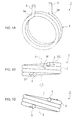
- torsion spring 1 shown in FIG. 1A receives a load in a direction in which hook sections 3 that are formed by bending both ends of coil section 2 separate from or approach each other in a circumferential direction, as shown in FIG. 1B , a rotational moment M is generated in coil section 2 of torsion spring 1 in accordance with the magnitude of the load acting on hook sections 3. Therefore, in torsion spring 1, from the state shown in FIG. 1B , winding center axis L of coil section 2 inclines relative to the position of central axis L in FIG. 1B , as shown in FIG. 1C .
- torsion spring 1 when torsion spring 1 receives a load in a direction in which hook sections 3 at both ends of coil section 2 separate from or approach each other in the circumferential direction, stress concentrates at bend sections 3a of hook sections 3, and the most bending stress in the member forming torsion spring 1 arises at bend sections 3a of hook sections 3. Therefore, from the viewpoint of repeated bending fatigue of the spring material, in general, an upper limit of a load that actuates torsion spring 1 is set by taking into account the bending stress that acts on bend sections 3a of hook sections 3.
- torsion spring 1 since the working load of torsion spring 1 is restricted by the bending stress that acts on bend sections 3a of hook sections 3, in some cases the working load thereof can not be freely set to a larger amount even if a margin exists with respect to the amount of stress that acts on coil section 2 that is the main body of the spring.
- a combination torsion spring employs a configuration including a first torsion spring and a second torsion spring that each have a coil section in which hook sections are formed at both ends thereof, in which: the first torsion spring and the second torsion spring are formed so that directions in which the coil sections are wound in a helical shape are different to each other, and an inner diameter of the coil section of the first torsion spring is approximately equal to an outer diameter of the coil section of the second torsion spring; and the coil section of the second torsion spring is inserted through inside of the coil section of the first torsion spring.
- a shift mechanism moves shift forks connected to a gear of a transmission using bias of a combination torsion spring having the above described configuration
- the shift mechanism employing a configuration including: a shift cam that has, on an outer periphery, cam grooves to which the shift forks are connected, and rotates to move the shift forks at a certain rotation angle; a cam phase holding section that holds the shift cam at phases determined per the certain rotation angle; a rotating section that is provided so as to be able to rotate in forward and reverse directions from a reference position, and rotates to rotate the shift cam through the certain rotation angle; a transferring section that rotates in one of the forward and reverse directions from the reference rotation position by rotation power of a motor, and transfers torque to the rotating section via the combination torsion spring in which bias increases accompanying an increase in a rotation angle of the rotation thereof; and a rotation regulating section that, while the transferring section is rotating in the one direction, regulates the rotation of the rotating section until a predetermined rotation angle is reached
- Bias by the combination torsion spring that increases following the rotation of the transferring section in one direction is accumulated, and when the rotation angle of the transferring section reaches a predetermined rotation angle, bias that is accumulated is transferred in the form of large torque to the rotating section.
- large torque is transferred to a shift cam via a rotating section and moves shift forks and gears connected to the shift forks with great force.
- a predetermined reaction force in a direction of a coil circumference can be suitably obtained without a winding center of a coil section inclining even under a load.
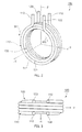
- Combination torsion spring (hereunder, referred to as "combination spring") 100 shown in FIG. 2 and FIG. 3 includes first torsion spring 110 and second torsion spring 120. Note that, in FIG. 2 and FIG. 3 , combination spring 100 is shown as a combination spring that is in a predetermined attachment state.
- First torsion spring 110 and second torsion spring 120 have coil sections 111 and 121, respectively, that are formed by winding steel wires in a helical shape in mutually different winding directions.
- coil section 111 of first torsion spring 110 is formed in a tubular shape by winding a steel wire in a helical shape in the clockwise direction (W1 direction) from one end (end on a side of hook section 113 that is described later).
- coil section 121 of second torsion spring 120 is formed in a tubular shape by winding a steel wire in a helical shape from one end (end on a side of hook section 122 that is described later) in a winding direction (W2 direction; corresponds to the counterclockwise direction as viewed from the X-direction side) that is different to the winding direction of first torsion spring 110.
- W2 direction corresponds to the counterclockwise direction as viewed from the X-direction side
- Combination spring 100 is constituted by combining first torsion spring 110 and second torsion spring 120 so that coil sections 111 and 121 overlap in a manner in which their respective axes are coaxial.
- the inner diameter of coil section 111 of first torsion spring 110 and the outer diameter of coil section 121 of second torsion spring 120 are approximately the same diameter.
- Coil section 121 of second torsion spring 120 is inserted through the inside of coil section 111 of first torsion spring 110.
- First torsion spring 110 and second torsion spring 120 include rod-shaped hook sections 112 and 113, and 122 and 123 that are bent in the radial direction (in this case, a radiation direction) from both ends of respective coil sections 111 and 121.
- first torsion spring 110 respective hook sections 112 and 113 protrude in parallel or substantially in parallel with each other from the two ends of coil section 111.
- second torsion spring 120 respective hook sections 122 and 123 protrude in parallel or substantially in parallel with each other from the two ends of coil section 121.
- first torsion spring 110 and second torsion spring 120 hook section 112 of first torsion spring 110 and hook section 122 of second torsion spring 120 are arranged so as to be aligned along the winding center axis of the coils. Further, hook section 113 of first torsion spring 110 and hook section 123 of second torsion spring 120 are arranged so as to be aligned along the winding center axis of the coils.
- first torsion spring 110 and second torsion spring 120 are combined so that coil section 121 of second torsion spring 120 is inserted inside coil section 111 of first torsion spring 110 so as to be movable in the circumferential direction, and so that hook sections 112, 113, 122, and 123 are positioned at positions that sandwich coil sections 111 and 121 in the direction of the winding center axis of the coils.
- combination spring 100 is in a predetermined attachment state, and an initial bias in a direction in which hook section 112 and hook section 113 approach each other in the circumferential direction is applied to first torsion spring 110 by members that impart a load to hook sections 112 and 113 (for example, latch sections 873 and 892 shown in FIG. 4 ). Further, an initial bias in a direction in which hook section 122 and hook section 123 approach each other in the circumferential direction is applied to second torsion spring 120 by members that impart a load to hook sections 122 and 123 (for example, latch sections 873 and 892 shown in FIG. 4 ).
- first torsion spring 110 and second torsion spring 120 perform the same action at the same time. That is, hook section 112 of first torsion spring 110 and hook section 122 of second torsion spring 120 are moved simultaneously in the circumferential direction relative to hook section 113 of first torsion spring 110 and hook section 123 of second torsion spring 120. Similarly, hook sections 113 and 123 are moved in the circumferential direction relative to hook sections 112 and 122.
- combination spring 100 constituted in this manner, as shown in FIG. 3 , when a force in direction P in which the set of hook sections 123 and 113 and the set of hook sections 112 and 122 move away from each other acts on the aforementioned sets, stress (a load) applied at bend sections between hook sections 112, 113, 122, and 123 and coil sections 111 and 121 is dispersed to and shared by both first torsion spring 110 and second torsion spring 120, and thus stress applied to respective hook sections 112, 113, 122, and 123 is reduced by half in comparison to hook sections in the case of a single torsion spring. That is, in first torsion spring 110 and second torsion spring 120, stress applied to hook sections 112, 113, 122, and 123 can be markedly alleviated.
- Combination spring 100 configured as described above can be used in mechanism portions in various fields to obtain a desired reaction force, that is, can move a member constituting a mechanism portion by means of accumulated bias.
- a shift mechanism will now be described as a mechanism in which combination spring 100 is used.
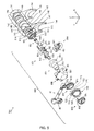
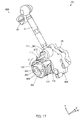
- FIG. 4 is a perspective view of shift mechanism 701
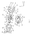
- FIG. 5 is an exploded perspective view of shift mechanism 701
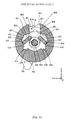
- FIG. 6 is a cross-sectional view of shift mechanism 701.
- FIG. 7 is a partial exploded perspective view showing part of shift mechanism 701 viewed from a different direction to that in FIG. 4 .
- shift mechanism 701 is illustrated in a standard state (see FIG. 15 ).
- shift mechanism 701 includes shift cam 14, shift forks 141 through 144, and shift cam drive unit 800 that is equipped with combination spring 100.
- Shift cam 14 has a cylindrical shape.
- Four cam grooves 14a through 14d are formed in the outer periphery of shift cam 14, and pin sections at the base end of shift forks 141 through 144 are placed so as to be movable within the respective grooves of four cam grooves 14a through 14d.
- These shift forks 141 through 144 are movable in the axial direction of the rotation axis of shift cam 14 in accordance with the shape of cam grooves 14a through 14d of rotating shift cam 14.
- a plurality of groove sections 145 are formed in one end of the outer peripheral surface of shift cam 14. In this embodiment, six groove sections 145 are formed at 60° intervals around the axial center of shift cam 14.
- throughhole 146 is formed in the center part of one side surface of shift cam 14.
- latch hole 147 is formed at a position deviating from the center part of the other side surface of shift cam 14.
- shift cam drive unit 800 includes first rotating member 801, positioning shaft 802 ( FIG. 5 and FIG. 6 ), second rotating member 803, regulating member 804 ( FIG. 5 and FIG. 6 ), third rotating member 805 ( FIG. 5 and FIG. 6 ), accommodating member 806, first transferring member 807, combination spring 100, and second transferring member 809.
- first rotating member 801 has small-diameter cylindrical section 811 and large-diameter cylindrical section 812. As shown in FIG. 4 through FIG. 7 , a plurality of projecting sections 813 with an approximately triangular cross-section are formed on the outer periphery of first rotating member 801 so as to project radially outward. In this embodiment, six projecting sections 813 are formed at 60° intervals around the axial center of first rotating member 801. Also, concave sections 814 formed by adjacent projecting sections 813 are formed in the circumferential direction.
- throughhole 815 is formed in the center part of a side surface of cylindrical section 811.
- latch hole 816 is formed at a position deviating from the center part of a side surface of cylindrical section 811.
- One end of positioning shaft 802 is inserted into throughhole 146 and throughhole 815.
- the rotation axis of shift cam 14 and the rotation axis of first rotating member 801 are provided on the same axis line.
- cylindrical section 811 and shift cam 14 are coupled so that latch member 822 is fitted into latch hole 147 and latch hole 816. By this means, it becomes possible for shift cam 14 and first rotating member 801 to rotate integrally.
- Springs 791 and 792 are provided inside mission case 770. Moving member 793 is abutted against one end of spring 791. Moving member 793 is provided so as to be movable in the axial direction of spring 791. Also, moving member 794 is abutted against one end of spring 792. Moving member 794 is provided so as to be movable in the axial direction of spring 792.
- Ball 795 is provided between moving member 793 and one end of the outer peripheral surface of shift cam 14. Ball 795 is biased toward shift cam 14 by spring 791 via moving member 793. Also, ball 796 is provided between moving member 794 and the outer peripheral surface of first rotating member 801 (an area formed by projecting section 813 and concave section 814 ( FIG. 5 )).
- Ball 796 is biased toward first rotating member 801 by spring 792 via moving member 794. Details of first rotating member 801 will be given later herein.
- First rotating member 801, projecting section 813, concave section 814, springs 791 and 792, balls 795 and 796 and so on correspond to a cam phase holding means for holding shift cam 14 in phases determined per a certain rotation angle (30° with the present embodiment).
- Groove section 145, concave section 814, springs 791 and 792, balls 795 and 796 and so on correspond to a torque supply section for supplying torque to shift cam 14.
- the set of spring 792, moving member 794, ball 796, projecting section 813 and concave section 814, and the set of spring 791, moving member 793, ball 795, and groove section 145 are each able to supply torque to the rotation direction while shift cam 14 is rotating.
- second rotating member 803 has rotor 831 and shaft section 832 formed so as to extend in the axial direction of that rotor 831.
- cylindrical hole 833 is formed in the axial center section of rotor 831.
- rotor 831 includes first ratchet 301, second ratchet 302, and cylindrical coupling section 303 that is provided so as to couple first ratchet 301 and second ratchet 302.
- lug plates 834 and 835 are attached to first ratchet 301, and lug plates 836 and 837 are attached to second ratchet 302.
- the other end of positioning shaft 802 is inserted into hole 833.
- the rotation axis of shift cam 14, the rotation axis of first rotating member 801, and the rotation axis of second rotating member 803 are provided on the same axis line.
- an installation space in a direction perpendicular to the rotation axis of shift cam 14, the rotation axis of first rotating member 801, and the rotation axis of second rotating member 803 is decreased without each of the aforementioned rotation axes being aligned parallel to each other.
- First ratchet 301 is accommodated inside cylindrical section 812.
- regulating member 804 is disk-shaped. As shown in FIG. 7 , first concave section 401 is formed in the center part of the surface of regulating member 804 on the +X direction side. Also, as shown in FIG. 5 , second concave section 402 is formed in the center part of the surface of regulating member 804 on the -X direction side.
- latch section 841 is formed on regulating member 804 so as to extend upward from the center part. As shown in FIG. 6 , coupling section 303 of second rotating member 803 is fitted into latch section 841.
- third rotating member 805 has first cylindrical section 851, second cylindrical section 852, and third cylindrical section 853.
- second rotating member 803 is provided rotatably inside third rotating member 805, second ratchet 302 is accommodated inside first cylindrical section 851, and one end of shaft section 832 projects from one end of third cylindrical section 853.
- accommodating member 806 has flange 861 and cylindrical accommodating section 862. As shown in FIG. 6 , flange 861 is attached to mission case 770. By this means, accommodating member 806 is fixed. Regulating member 804 is fixed to accommodating member 806.
- Third rotating member 805 is provided rotatably inside accommodating member 806.
- First cylindrical section 851 and second cylindrical section 852 are accommodated inside accommodating section 862.
- Third cylindrical section 853 projects from one end of accommodating member 806.
- first transferring member 807 has disk-shaped main unit 871 and coupling section 872.
- Coupling section 872 is formed so as to extend upward from the outer periphery of main unit 871.
- Plate-shaped latch section 873 is formed on coupling section 872 so as to extend in the -X direction.
- main unit 871 is fixed to third cylindrical section 853 in third rotating member 805.
- coupling section 872 is coupled to one end of drive mechanism 41.
- the other end of drive mechanism 41 is coupled to the rotating shaft (not shown) of motor 8 (see FIG. 6 ).
- Third rotating member 805 and first transferring member 807 correspond to a transferring section that rotates by rotation power of motor 8 (see FIG. 6 ) in one of the forward and reverse directions from the reference rotation position, and by transferring that rotation to the rotating section (second transferring member 809, second rotating member 803, first ratchet 301, and first rotating member 801) via combination spring 100, makes the rotating section rotate.
- Combination spring 100 increases bias following increase in the rotation angle of the rotation of third rotating member 805, first transferring member 807 or corresponding transmitting means in one direction. That is, in the combination spring, accompanying rotation of the transferring section in one of the forward and reverse directions from the reference rotation position, hook section 113 at the one end of coil section 111 of first torsion spring 110 and hook section 123 at the other end of coil section 121 of second torsion spring 120 accumulate the aforementioned bias by moving in the circumferential direction of respective coils 111 and 121 simultaneously relative to hook section 112 at the other end of coil section 111 of first torsion spring 110 and hook section 122 at the one end of coil section 121 of second torsion spring 120.
- Combination spring 100 accumulates increasing bias of combination spring 100 together with latch section 873, first transferring member 807, third rotating member 805, regulating member 804, second ratchet 302, second rotating member 803, second transferring member 809, and latch section 892.
- Regulating member 804, second ratchet 302, second rotating member 803, and third rotating member 805 correspond to a rotation regulating section.
- the rotation regulating section regulates the rotation of the rotating section constituted by second transferring member 809, second rotating member 803, first ratchet 301 and first rotating member 801 until a predetermined rotation angle is reached during rotation of third rotating member 805 and first transferring member 807 in one direction.
- regulating member 804, second ratchet 302, and third rotating member 805 enable rotation of the rotating section in the one direction that is the rotation direction of third rotating member 805 and first transferring member 807.
- the rotating section first rotating member 801, second rotating member 803, second transferring member 809, and first ratchet 301 transfers torque that is accumulated by combination spring 100 and that is biased towards second transferring member 809 and second rotating member 803 in the form of torque to first rotating member 801 via first ratchet 301.
- Second transferring member 809 has disk-shaped main unit 891 and latch section 892, having an approximately L-shaped cross-section, formed on the upper part of main unit 891.
- Latch section 892 is formed so that its front end extends in the +X direction.
- Second transferring member 809 and second rotating member 803 correspond to a rotating means that rotates shift cam 14 at a certain rotation angle (30°, for example).
- the rotation regulating section regulating member 804, second ratchet 302, second rotating member 803, and third rotating member 805
- torque that is accumulated by combination spring 100 and that is biased towards second transferring member 809 and second rotating member 803 is transferred to first rotating member 801 via first ratchet 301.
- the rotating section rotates at a certain rotation angle (for example, 30°) in the one direction together with shift cam 14 that is held by the cam phase holding section.
- main unit 891 of second transferring member 809 is fixed to one end of shaft section 832 in second rotating member 803.
- One end of main unit 871 in first transferring member 807 and one end of main unit 891 in second transferring member 809 are fitted inside the inner diameter of combination spring 100 (inner diameter of second torsion spring 120).
- main unit 871 and main unit 891 become the approximate rotation axis of combination spring 100.
- latch section 873 of first transferring member 807 and latch section 892 of second transferring member 809 are arranged between a hook set of hook sections 122 and 112 (hereunder, may also be referred to as "first hook set”) and a hook set of hook sections 113 and 123 (hereunder, may also be referred to as "second hook set”) of combination spring 100. Also, as shown in FIG. 4 and FIG. 6 , latch section 873 is provided above latch section 892, with a gap between the two.
- the first hook set or the second hook set is pressed by relative movement of latch section 873 and latch section 892, and moves around the rotation axis.
- bias is accumulated in coil sections 111 and 121 in combination spring 100.
- shift cam drive unit 800 will now be described using accompanying drawings.
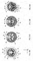
- FIG. 8 is a cross-sectional view of the part of shift mechanism 701 indicated by line A-A in FIG. 6
- FIG. 9 is a cross-sectional view of the part of shift mechanism 701 indicated by line B-B in FIG. 6
- FIG. 10 is a cross-sectional view of the part of shift mechanism 701 indicated by line C-C in FIG. 6
- FIG. 11 is a cross-sectional view of the part of shift mechanism 701 indicated by line D-D in FIG. 6
- FIG. 12 is a perspective view showing first rotating member 801 and regulating member 804, and FIG. 13 and FIG.
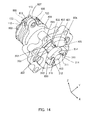
- FIG. 14 are perspective views showing second rotating member 803, regulating member 804, third rotating member 805, accommodating member 806, first transferring member 807, combination spring 100, and second transferring member 809.
- FIG. 15 is a perspective view showing second rotating member 803 and regulating member 804, and
- FIG. 16 is a perspective view showing second rotating member 803 and third rotating member 805.
- chamfering surface 131 is formed at the apex of each of projecting sections 813.
- Chamfering surface 131 is formed by a predetermined circumferential surface centered on the axial center of first rotating member 801.
- chamfering surfaces 131 and groove sections 145 are placed on approximately the same radius centered on positioning shaft 802, and first rotating member 801 and shift cam 14 are coupled.
- ball 795 and ball 796 are placed in the YZ plane so that the direction of the center point of ball 795 with respect to positioning shaft 802, and the direction of the center point of ball 796 with respect to positioning shaft 802, are identical.
- inner peripheral surface 817 of cylindrical section 812 has a concavo-convex shape.
- concave surfaces 818 with an approximately V-shaped cross-section are formed in inner peripheral surface 817 at 30° intervals around the axial center of cylindrical section 812.
- concave section 311 and concave section 312 are formed in first ratchet 301 (see FIG. 8 ) so as to curve inward.
- First fan-shaped section 313 is formed on the upper part of first ratchet 301
- second fan-shaped section 314 is formed on the lower part of first ratchet 301.
- First ratchet 301 is formed so as to be symmetrical with respect to a plane through the center in the YZ plane of fan-shaped section 313 including the rotation axis of second rotating member 803, and have a uniform shape in the X direction.
- one end of lug plate 834 is fitted into a curving corner on the upper side of concave section 311.
- Lug plate 834 is provided so as to be able to pivot about one end.
- one end of lug plate 835 is fitted into a curving corner on the upper side of concave section 312, and lug plate 835 is provided so as to be able to pivot about one end.
- the other end of lug plate 834 denotes the front end of lug plate 834
- the other end of lug plate 835 denotes the front end of lug plate 835.
- Hole 315 is formed in second fan-shaped section 314 on the concave section 311 side. Hole 315 is formed so as to extend from the center part of the lower part of second fan-shaped section 314 toward the lower corner of concave section 311. Also, hole 316 is formed in second fan-shaped section 314 on the concave section 312 side. Hole 316 is formed so as to extend from the center part of the lower part of second fan-shaped section 314 toward the lower corner of concave section 312.
- Spring 317 is provided inside hole 315. One end of spring 317 is abutted against the lower surface of lug plate 834. In this embodiment, spring 317 dimensions are set so that, in a standard state, the front end surface of lug plate 834 faces the lower inclined surface of concave surface 818 positioned in the +Y direction of positioning shaft 802 in a state in which it is brought close thereto.
- spring 318 is provided inside hole 316. One end of spring 318 is abutted against the lower surface of lug plate 835.
- the dimensions of spring 318 are set so that, in a standard state, the front end surface of lug plate 835 faces the lower inclined surface of concave surface 818 positioned in the -Y direction of positioning shaft 802 in a state in which it is brought close thereto.
- the +X direction sides of lug plates 834 and 835 are accommodated inside cylindrical section 812. Also, as shown in FIG. 9 and FIG. 12 through FIG. 14 , the -X direction sides of lug plates 834 and 835 are accommodated inside first concave section 401 of regulating member 804.
- first concave section 401 and second concave section 402 are formed so as to be symmetrical with respect to a plane passing through the center in the YZ plane of fan-shaped section 313 in a standard state including the rotation axis of second rotating member 803, and have a uniform shape in the X direction.
- first concave section 401 has guiding surface 411, auxiliary surface 412, partial cylindrical section 413, and latching surface 414 provided in order from above on the +Y direction side, together with guiding surface 415, auxiliary surface 416, partial cylindrical section 417, and latching surface 418 provided in order from above on the -Y direction side.
- guiding surface 411 is formed so as to extend downward obliquely from the latch section 841 side. Guiding surface 411 curves gently so as to become convex in the outward direction of regulating member 804 in the YZ plane. Also, guiding surface 411 is provided farther inward (on the inner diameter) than inner peripheral surface 817 of cylindrical section 812 in the YZ plane.
- Auxiliary surface 412 is formed so as to become approximately coplanar with the upper inclined surface of concave surface 818 positioned to the side of positioning shaft 802 in a standard state.
- Partial cylindrical section 413 is formed so as to be positioned on the circumference of a predetermined circle with the axial center of second rotating member 803 as its center. Partial cylindrical section 413 is provided farther outward (on the outer diameter) than inner peripheral surface 817.
- Latching surface 414 is formed so as to be approximately parallel to the upper inclined surface in concave surface 818 one down from concave surface 818 positioned to the side of positioning shaft 802 in a standard state. Also, the distance between latching surface 414 and the above-mentioned inclined surface is set so as to be approximately equal to the thickness of lug plate 834. Latching surface 414 is formed so as to extend as far as a position farther inward (on the inner diameter) than inner peripheral surface 817 of cylindrical section 812 in the YZ plane.
- Guiding surface 415, auxiliary surface 416, partial cylindrical section 417, and latching surface 418 are formed in the same way, respectively, as guiding surface 411, auxiliary surface 412, partial cylindrical section 413, and latching surface 414.
- second concave section 402 has upper surface 421, partial cylindrical section 422, trigger surface 423, open surface 424, bottom surface 425, and latching surface 426 provided in order from above on the +Y direction side, together with upper surface 431, partial cylindrical section 432, trigger surface 433, open surface 434, bottom surface 435, and latching surface 436 provided in order from above on the -Y direction side.
- upper surface 421 is formed so as to extend in the +Y direction from the side of latch section 841.
- Partial cylindrical section 422 is formed so as to be positioned on the circumference of a predetermined circle with the axial center of second rotating member 803 as its center.
- Trigger surface 423 is formed so as to extend downward obliquely in an approximately horizontal direction of positioning shaft 802.
- Open surface 424 is formed so as to extend in an approximately vertical direction farther than partial cylindrical section 422 on the positioning shaft 802 side.
- Bottom surface 425 is formed so as to incline gently.
- Latching surface 426 is formed so as to extend upward obliquely.
- Upper surface 431, partial cylindrical section 432, trigger surface 433, open surface 434, bottom surface 435, and latching surface 436 are formed in the same way, respectively, as upper surface 421, partial cylindrical section 422, trigger surface 423, open surface 424, bottom surface 425, and latching surface 426.
- first cylindrical section 851 has partial cylindrical section 511 and partial cylindrical section 512. Inclined surfaces 513 and 514 are formed on first cylindrical section 851 so as to connect the inner peripheral surface of partial cylindrical section 511 and the inner peripheral surface of partial cylindrical section 512.
- the inner peripheral surface of partial cylindrical section 511 is provided on the circumference of a predetermined circle with the axial center of second rotating member 803 as its center (hereinafter referred to as "first circle”). Also, the inner peripheral surface of partial cylindrical section 512 is provided on the circumference of a predetermined circle with the axial center of second rotating member 803 as its center and of greater diameter than the first circle (hereinafter referred to as "second circle”).
- the radius of the above-described first circle is smaller than the distance between corner 211 formed by trigger surface 423 and open surface 424 and the axial center of second rotating member 803, and is also smaller than the distance between corner 212 formed by trigger surface 433 and open surface 434 and the axial center of second rotating member 803.
- the radius of the above-described second circle is greater than the distance between corner 221 formed by open surface 424 and bottom surface 425 and the axial center of second rotating member 803, and is also greater than the distance between corner 241 formed by open surface 434 and bottom surface 435 and the axial center of second rotating member 803.
- partial cylindrical section 511 and partial cylindrical section 512 are formed so that inclined surfaces 513 and 514 are positioned higher than trigger surfaces 423 and 433 in a standard state.
- concave section 321 and concave section 322 are formed in second ratchet 302 so as to curve inward.
- first fan-shaped section 323 is formed on the upper part of second ratchet 302
- second fan-shaped section 324 is formed on the lower part of second ratchet 302.
- Second ratchet 302 is formed so as to be symmetrical with respect to a plane through the center in the YZ plane of fan-shaped section 323 including the rotation axis of second rotating member 803, and have a uniform shape in the X direction.
- one end of lug plate 836 is fitted into a curving corner on the upper side of concave section 321. And lug plate 836 is provided so as to be able to pivot about one end. Also, one end of lug plate 837 is fitted into a curving corner on the upper side of concave section 322, and lug plate 837 is provided so as to be able to pivot about one end.
- the other end of lug plate 836 denotes the front end of lug plate 836
- the other end of lug plate 837 denotes the front end of lug plate 837.
- Hole 325 is formed in second fan-shaped section 324 on the concave section 321 side. Hole 325 is formed so as to extend from the center part of the lower part of second fan-shaped section 324 toward the lower corner of concave section 321. Also, hole 326 is formed in second fan-shaped section 324 on the concave section 322 side. Hole 326 is formed so as to extend from the center part of the lower part of second fan-shaped section 324 toward the lower corner of concave section 322.
- Spring 327 is provided inside hole 325. One end of spring 327 is abutted against the lower surface of lug plate 836. In this embodiment, the dimensions of spring 327 arc set so that, in a standard state, the front end surface of lug plate 836 faces trigger surface 423 in a state in which it is brought close thereto.
- spring 328 is provided inside hole 326. One end of spring 328 is abutted against the lower surface of lug plate 837. In this embodiment, the dimensions of spring 328 are set so that, in a standard state, the front end surface of lug plate 837 faces trigger surface 433 in a state in which it is brought close thereto.
- the +X direction sides of lug plates 836 and 837 are accommodated inside second concave section 402 of regulating member 804. Also, as shown in FIG. 11 and FIG. 16 , the -X direction sides of lug plates 836 and 837 are accommodated inside first cylindrical section 851 in third rotating member 805.
- shift mechanism 701 when gear shifting is performed will now be described in detail using accompanying drawings. A case will be described below in which the unshown shift-up button is depressed by the rider.
- FIG. 17 through FIG. 26 are drawings for explaining the operation of shift mechanism 701 when gear shifting is performed.
- FIG. 17 and FIG. 18 are perspective views of shift cam drive unit 800.
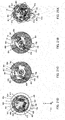
- the respective drawings A through D in FIG. 19 through FIG. 26 are cross-sectional views of the parts of shift mechanism 701 indicated by line A-A, line B-B, line C-C, and line D-D in FIG. 6 , respectively.
- each drawing A in FIG. 19 through FIG. 26 is a cross-sectional view of the part of shift mechanism 701 indicated by line A-A in FIG. 6
- each drawing B in FIG. 19 through FIG. 26 is a cross-sectional view of the part of shift mechanism 701 indicated by line B-B in FIG. 6 .
- FIG. 19 through FIG. 26 is a cross-sectional view of the part of shift mechanism 701 indicated by line C-C in FIG. 6
- each drawing D in FIG. 19 through FIG. 26 is a cross-sectional view of the part of shift mechanism 701 indicated by line D-D in FIG. 6
- FIG. 19A through D show cross-sections of the respective parts in a standard state (corresponding to the cross-sectional views in FIG. 8 through FIG. 11 ).
- shift cam 14 has its rotation constrained through ball 795 being biased toward shift cam 14 in groove section 145 by spring 791 via moving member 793. The torque that constrains the rotation of shift cam 14 due to ball 795 will be described in detail later herein.
- motor 8 When the rider depresses the shift-up button, motor 8 (see FIG. 2 ) is controlled by unshown ECU, and the rotating shaft (not shown) of motor 8 rotates through a predetermined angle (in this embodiment, approximately 40°). As shown in FIG. 4 through FIG. 6 and FIG. 17 , swing arm 42 is connected to the rotating shaft of motor 8, and through the rotation of the rotating shaft of motor 8, swing arm 42 is rotated and drive mechanism 41 is moved in approximately Y-axial direction. By this means, as shown in FIG. 17 , first transferring member 807 is rotated in the direction indicated by arrow R by drive mechanism 41. In the following description, rotation in the arrow R direction denotes counterclockwise rotation, and rotation in the opposite direction denotes clockwise rotation. Rotation in one of these clockwise and counterclockwise directions corresponds to rotation in the forward direction and rotation in the other direction corresponds to rotation in the reverse direction.
- first transferring member 807 Through the counterclockwise rotation of first transferring member 807, the second hook set (hook sections 113 and 123) of combination spring 100 is pressed in the counterclockwise direction by latch section 873. As a result, counterclockwise torque (reaction force) is generated in the first hook set (hook sections 112 and 122) of combination spring 100.
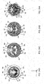
- the front end surface of lug plate 836 faces trigger surface 423 of regulating member 804 in a state in which it is brought close thereto.
- the front end surface of lug plate 836 abuts trigger surface 423 immediately after the start of that rotation operation.
- movement of lug plate 836 is stopped, and rotation of second rotating member 803 is stopped.
- third rotating member 805 alone rotates while second rotating member 803 is stopped, as shown in FIG. 19D and FIG. 20D .
- latch section 873 and latch section 892 are distanced from each other, and counterclockwise torque is accumulated in combination spring 100.
- third rotating member 805 rotates through a predetermined angle (for example, approximately 32.5°) from a standard state, lug plate 836 is fully pushed out from the top of trigger surface 423 by inclined surface 513.
- a predetermined angle for example, approximately 32.5°
- the torque accumulated in combination spring 100 is biased, and regulation of the rotation of second transferring member 809 and second rotating member 803 for which counterclockwise rotation (the same as first transferring member 807 and third rotating member 805) had been regulated is released.
- second rotating member 803 rotates counterclockwise while moving the front end surface of lug plate 836 toward bottom surface 425 along open surface 424.
- shift cam 14 rotates due to the rotation of first rotating member 801. Torque biased in a counterclockwise direction on the first rotating member 801 and shift cam 14 from combination spring 100 via second transferring member 809, second rotating member 803, and lug plate 834 at this time is set larger than torque whereby ball 795 constrains the rotation of shift cam 14 in the standard state.
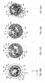
- lug plate 834 abuts latching surface 414 when second rotating member 803 rotates counterclockwise through approximately 30°. By this means, the rotation angle of second rotating member 803 is limited to approximately 30°. Also, as shown in FIG. 22D , lug plate 836 abuts latching surface 426 when third rotating member 805 rotates counterclockwise through approximately 45°. By this means, the rotation angle of third rotating member 805 is limited to approximately 45°.
- the possible rotation angle of third rotating member 805 is set larger than the possible rotation angle of second rotating member 803.
- the rotating shaft of motor 8 can be rotated so that the rotation angle of third rotating member 805 becomes 30° or more, facilitating control of motor 8 (see FIG. 6 ) by unshown ECU.
- second rotating member 803 can be rotated dependably, and shift cam 14 can be rotated dependably.
- motor 8 is again controlled by ECU, and the rotating shaft of motor 8 rotates through a predetermined angle (in this embodiment, approximately 40°). In other words, the rotating shaft is restored to its original position.
- first transferring member 807 and third rotating member 805 rotate clockwise through approximately 45°.
- third rotating member 805 returns to its original position (the same position as in the standard state) as shown in FIG. 23 .
- latch section 892 of second transferring member 809 has its rotation constrained by latch section 873 of first transferring member 807 and the first hook set (hook sections 112 and 122) and the second hook set (hook sections 113 and 123) of combination spring 100, and rotates clockwise together with first transferring member 807.
- Torque that constrains the relative rotation of latch section 892 and latch section 873 by means of combination spring 100 at this time is set larger than torque regulating the relative rotation of second rotating member 803 and first rotating member 801 through lug plate 834 pressing against inner peripheral surface 817 due to the extension of spring 317 when second rotating member 803 moves from the position in FIG. 22 to the position in FIG. 23 .
- second rotating member 803 returns to its original position (the same position as in the standard state) together with third rotating member 805.
- first rotating member 801 When second rotating member 803 moves from the position in FIG. 22 to the position in FIG. 23 , first rotating member 801 has its rotation constrained by ball 796 being biased toward first rotating member 801 by spring 792 via moving member 794 in concave section 814 of the outer peripheral surface of first rotating member 801. Torque that constrains the rotation of first rotating member 801 by means of ball 796 at this time is set larger than torque regulating the relative rotation of second rotating member 803 and the first rotating member through lug plate 834 pressing against inner peripheral surface 817 due to the extension of spring 317. The torque whereby ball 796 constrains the rotation of first rotating member 801 will be described in detail later herein.
- auxiliary surface 416 is formed so as to be approximately coplanar with the upper inclined surface of concave surface 818. Therefore, when second rotating member 803 moves from the position in FIG. 22 to the position in FIG. 23 , rotation of first rotating member 801 via lug plate 835 is stopped.
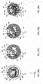
- motor 8 (see FIG. 6 ) is again controlled by unshown ECU, and, as shown in FIG. 23 through FIG. 26 , first rotating member 801 and shift cam 14 rotate counterclockwise through approximately 30° in the same way as in FIG. 19 through FIG. 22 .
- one of shift forks 141 through 144 moves.
- either the odd-numbered gear group or the even-numbered gear group is set to a neutral position.
- motor 8 (see FIG. 2 ) is again controlled by unshown ECU, and third rotating member 805 rotates clockwise through approximately 45°.
- second rotating member 803 is returned to its position in the standard state (the state in FIG. 19 ) while shift cam 14 and first rotating member 801 are stopped.
- a gear shift in transmission mechanism 700 ends.
- second rotating member 803 is rotated in the opposite direction to the rotation direction described with reference to FIG. 19 through FIG. 26 .
- FIG. 27 is a drawing showing torque imparted to shift cam 14 and first rotating member 801 when shift cam 14 rotates through 60° from one standard state to the next standard state.
- the vertical axis in FIG. 27 indicates torque [Nm] imparted to shift cam 14 and first rotating member 801, and the horizontal axis indicates the rotation angle [deg] from a standard state of shift cam 14 and first rotating member 801. Therefore, rotation angles 0° and 60° in FIG. 27 indicate standard states of shift cam 14 and first rotating member 801.
- torque in a counterclockwise direction is shown as a positive value
- torque in a clockwise direction is shown as a negative value.
- dash-dot line A indicates torque imparted to shift cam 14 from spring 791 (see FIG. 6 ) via ball 795 (see FIG. 6 )
- dotted line B indicates torque imparted to first rotating member 801 from spring 792 (see FIG. 6 ) via ball 796 (see FIG. 6 ).
- solid line C indicates composite torque comprising the torque indicated by dash-dot line A and the torque indicated by dotted line B
- dashed line D indicates torque imparted to shift cam 14 and first rotating member 801 from combination spring 100
- dash-dot-dot line E indicates composite torque comprising the torque indicated by solid line C and the torque indicated by dashed line D. Therefore, the actual torque imparted to shift cam 14 is the value indicated by dash-dot-dot line E.
- ball 796 is positioned on chamfering surface 131 of projecting section 813.
- the direction of force imparted to first rotating member 801 from spring 792 (see FIG. 6 ) via ball 796 coincides with the radial direction of first rotating member 801. Consequently, torque is not imparted to first rotating member 801 from ball 796.
- Negative torque imparted to shift cam 14 from spring 791 reaches a maximum immediately after the start of a shift cam 14 rotation operation. Thereafter, the negative torque imparted to shift cam 14 from spring 791 decreases as the rotation angle of shift cam 14 increases.
- Ball 795 (see FIG. 8 ) is pushed completely out of groove section 145 when shift cam 14 has rotated through approximately 6° from the standard state (immediately before parts of a transmission gear and spline gear that fit together and are coupled through a dog mechanism come into contact).
- the point of contact between ball 795 and shift cam 14 is not positioned inside groove section 145, the direction of force imparted to shift cam 14 from spring 791 via ball 795 coincides with the radial direction of shift cam 14. Consequently, torque imparted to shift cam 14 from spring 791 at this time is 0, as indicated by dash-dot line A in FIG. 27 .
- groove section 145 is formed in such a way that ball 795 is pushed completely out of groove section 145 by the rotation of shift cam 14 through approximately ⁇ 6° or more from a standard state. Therefore, as indicated by dash-dot line A in FIG. 27 , when the rotation angle from a standard state (hereinafter abbreviated simply to "rotation angle") of shift cam 14 is within a range of approximately 6° to approximately 54°, torque imparted to shift cam 14 from spring 791 is 0.
- first rotating member 801 starts counterclockwise rotation, the point of contact between ball 796 and first rotating member 801 is positioned on chamfering surface 131 (see FIG. 8 ).
- the direction of force imparted to first rotating member 801 from spring 792 via ball 796 coincides with the radial direction of first rotating member 801. Consequently, torque is not imparted to first rotating member 801 from spring 792. That is to say, torque imparted to 801 from spring 792 is maintained at 0 as indicated by dotted line B in FIG. 27 .
- the positive torque imparted to first rotating member 801 from spring 792 indicated by dotted line B reaches a maximum when first rotating member 801 has rotated through approximately 6° from the standard state (immediately before parts of a transmission gear and spline gear that fit together and are coupled through a dog mechanism come into contact), and gradually decreases thereafter.
- the variability characteristic of torque imparted to first rotating member 801 from spring 792 and the rotation angle of first rotating member 801 at which the torque reaches a maximum are decided by the shape of projecting section 813.
- first rotating member 801 rotates through approximately 30° from a standard state
- ball 796 and first rotating member 801 come into contact with both sides of an undulating inclined surface reaching projecting sections 813 on the left and right of concave section 814 sandwiching the center of that concave section 814.
- moments in both directions acting upon first rotating member 801 through normal force at the left and right points of contact are in balance. Consequently, through pressure from spring 792, first rotating member 801 is held in a stable state in which there is holding torque in both directions circumferentially, as indicated by dotted line B in FIG. 27 .
- first rotating member 801 Through further counterclockwise rotation of first rotating member 801 from the position shown in FIG. 21A , the point of contact between ball 796 and first rotating member 801 moves to an undulating surface on the left side of concave section 814 shown by FIG. 21A . At this time, a moment acts upon first rotating member 801 due to normal force at the point of contact between ball 796 and first rotating member 801 receiving pressure from spring 792. That is to say, negative torque is imparted to first rotating member 801 from spring 792 as indicated by dotted line B in FIG. 27 .
- first rotating member 801 When first rotating member 801 has rotated through approximately 54° from the standard state, the negative torque imparted to first rotating member 801 from spring 792 indicated by dotted line B reaches a negative maximum. Thereafter, the torque imparted to first rotating member 801 from spring 792 becomes 0 when the point of contact between ball 796 and first rotating member 801 moves to a position on chamfering surface 131 (see FIG. 25A ).
- composite torque of torque imparted to shift cam 14 from spring 791 and torque imparted to first rotating member 801 from spring 792 is a negative value in the rotation angle range for shift cam 14 from 0° to approximately 2.5°, a positive value in the rotation angle range for shift cam 14 from approximately 2.5° to 30°, a negative value in the rotation angle range for shift cam 14 from 30° to approximately 57.5°, and a negative value in the rotation angle range for shift cam 14 from approximately 57.5° to 60°.
- shift cam 14 is held in a stable state in which there is holding torque in both rotation directions. By this means, it is possible to stabilize gears in the transmission. As a result, a vehicle is able to drive smoothly.
- torque accumulated in combination spring 100 (corresponding to a predetermined reaction force) is imparted to first rotating member 801 and shift cam 14 each time third rotating member 805 rotates through approximately 30° from a standard state.
- first rotating member 801 and shift cam 14 rotate through 30°.
- shift mechanism 701 In shift mechanism 701 according to this embodiment, torque combining torque imparted to shift cam 14 from springs 791 and 792 (solid line C in FIG. 27 ) and torque imparted to shift cam 14 from combination spring 100 (dashed line D in FIG. 27 ) is imparted to shift cam 14. That is to say, the value indicated by dash-dot-dot line E in FIG. 27 is imparted to shift cam 14.
- composite torque of torque imparted to shift cam 14 from spring 791 and torque imparted to first rotating member 801 from spring 792 has mostly a positive value in the rotation angle range for shift cam 14 from 0° to 30°, and mostly a negative value in the rotation angle range for shift cam 14 from 30° to 60°. Therefore, as indicated by dash-dot-dot line E, torque imparted to shift cam 14 in the rotation angle range for shift cam 14 from 0° to 30° is greater than torque imparted to shift cam 14 in the rotation angle range for shift cam 14 from 30° to 60°.
- torque imparted to shift cam 14 reaches a maximum when the rotation angle of shift cam 14 is approximately 6° (immediately before parts of a transmission gear and spline gear that fit together and are coupled through a dog mechanism come into contact).
- the magnitude of torque imparted to shift cam 14 can be set appropriately according to the configuration of shift mechanism 701 and the like.
- the magnitude of torque imparted to shift cam 14 can be changed by changing the spring constants and/or attachment loads of spring 791, spring 792, and combination spring 100 as appropriate.
- spring 791, spring 792, and combination spring 100 are provided so that torque in the opposite direction to the rotation direction of shift cam 14 in composite torque is not imparted to shift cam 14 when shift cam 14 is rotated.
- shift mechanism 701 that is configured in the above described manner, when combination spring 100 functions, stress concentrates at the respective bend sections between hook sections 112, 113, 122, and 123 and coil sections 111 and 121.
- combination spring 100 is constituted by two torsion springs, namely, first torsion spring 110 and second torsion spring 120, in comparison to a configuration that uses a single torsion spring, a load applied to respective hook sections 112, 113, 122, and 123 is reduced by half.
- first torsion spring 110 and second torsion spring 120 having respective directions in which coil sections 111 and 121 are wound in a helical shape and which are different to each other
- a configuration may also be adopted that combines three or more torsion springs.
- a combination torsion spring according to the present invention has an advantageous effect whereby a predetermined reaction force in a direction of a coil circumference can be suitably obtained without a winding center of a coil section inclining even under a load, and is suitable for use as a torsion spring employed in a shift mechanism mounted on a motor cycle.
Abstract
Description
- The present invention relates to a combination torsion spring and a shift mechanism equipped therewith.
- Torsion spring (torsion coil spring) 1 (see
FIGS. 1A through 1C ) that receives a torsional moment (torque) around a winding center axis (coil axis) of a coil section that is formed by winding a steel wire into a coil moves and stops a mechanism of a mechanical component and a mechanism of an electronic instrument. Consequently,torsion spring 1 is used in various forms as, for example, a shock absorber when storing or taking out a vehicle seat or the like as described in Patent Literature (hereinafter, abbreviated as PTL) 1, or a locking apparatus that fixes a display device at an arbitrary position as described inPTL 2. -
-
PTL 1
Japanese Patent Application Laid-Open No.HEI 6-144092 -
PTL 2
Japanese Patent Application Laid-Open No.HEI 10-222079 - In general, when
torsion spring 1 shown inFIG. 1A receives a load in a direction in whichhook sections 3 that are formed by bending both ends ofcoil section 2 separate from or approach each other in a circumferential direction, as shown inFIG. 1B , a rotational moment M is generated incoil section 2 oftorsion spring 1 in accordance with the magnitude of the load acting onhook sections 3. Therefore, intorsion spring 1, from the state shown inFIG. 1B , winding center axis L ofcoil section 2 inclines relative to the position of central axis L inFIG. 1B , as shown inFIG. 1C . As a result, since the relative distance betweenhook sections 3 changes in a direction that decreases the loads acting on hook sections 3 (loads in D1 and D2 directions that open to the left and right inFIG. 1B , that is, loads in directions away from each other that are perpendicular to the coil axis that act on hook sections 3), there is the problem that a predetermined reaction force can not be obtained fromtorsion spring 1. - Further, when
torsion spring 1 receives a load in a direction in which hooksections 3 at both ends ofcoil section 2 separate from or approach each other in the circumferential direction, stress concentrates atbend sections 3a ofhook sections 3, and the most bending stress in the member formingtorsion spring 1 arises atbend sections 3a ofhook sections 3. Therefore, from the viewpoint of repeated bending fatigue of the spring material, in general, an upper limit of a load that actuatestorsion spring 1 is set by taking into account the bending stress that acts onbend sections 3a ofhook sections 3. In other words, since the working load oftorsion spring 1 is restricted by the bending stress that acts onbend sections 3a ofhook sections 3, in some cases the working load thereof can not be freely set to a larger amount even if a margin exists with respect to the amount of stress that acts oncoil section 2 that is the main body of the spring. - It is therefore an object of the present invention to provide a combination torsion spring with which a predetermined reaction force in a direction of a coil circumference can be suitably obtained without a winding center of a coil section inclining even under a load, and a shift mechanism equipped therewith.
- A combination torsion spring according to one aspect of the present invention employs a configuration including a first torsion spring and a second torsion spring that each have a coil section in which hook sections are formed at both ends thereof, in which: the first torsion spring and the second torsion spring are formed so that directions in which the coil sections are wound in a helical shape are different to each other, and an inner diameter of the coil section of the first torsion spring is approximately equal to an outer diameter of the coil section of the second torsion spring; and the coil section of the second torsion spring is inserted through inside of the coil section of the first torsion spring.
- A shift mechanism according to another aspect of the present invention moves shift forks connected to a gear of a transmission using bias of a combination torsion spring having the above described configuration, the shift mechanism employing a configuration including: a shift cam that has, on an outer periphery, cam grooves to which the shift forks are connected, and rotates to move the shift forks at a certain rotation angle; a cam phase holding section that holds the shift cam at phases determined per the certain rotation angle; a rotating section that is provided so as to be able to rotate in forward and reverse directions from a reference position, and rotates to rotate the shift cam through the certain rotation angle; a transferring section that rotates in one of the forward and reverse directions from the reference rotation position by rotation power of a motor, and transfers torque to the rotating section via the combination torsion spring in which bias increases accompanying an increase in a rotation angle of the rotation thereof; and a rotation regulating section that, while the transferring section is rotating in the one direction, regulates the rotation of the rotating section until a predetermined rotation angle is reached and accumulates an increasing bias of the combination torsion spring, and when the rotation angle of the transferring section is at or beyond the predetermined rotation angle, allows the rotation of the rotating section and transfers the bias as torque to the rotating section; in which the rotating section rotates the shift cam that is held by the cam phase holding section using torque that is biased by the combination torsion spring.
- Bias by the combination torsion spring that increases following the rotation of the transferring section in one direction is accumulated, and when the rotation angle of the transferring section reaches a predetermined rotation angle, bias that is accumulated is transferred in the form of large torque to the rotating section. By this means, large torque is transferred to a shift cam via a rotating section and moves shift forks and gears connected to the shift forks with great force.
- According to the present invention, a predetermined reaction force in a direction of a coil circumference can be suitably obtained without a winding center of a coil section inclining even under a load.
-
-
FIG. 1A is a perspective view for explaining a conventional torsion spring; -
FIG. 1B is a top view for explaining the conventional torsion spring; -
FIG. 1C is a top view for explaining the conventional torsion spring; -
FIG. 2 is a perspective view of a combination spring according to an embodiment of the present invention; -
FIG. 3 is a plan view of the combination spring shown inFIG. 2 ; -
FIG. 4 is a perspective view showing a shift mechanism equipped with the combination spring shown inFIG. 2 ; -
FIG. 5 is an exploded perspective view of the shift mechanism shown inFIG. 4 ; -
FIG. 6 is a cross-sectional view of the shift mechanism shown inFIG. 4 ; -
FIG. 7 is an exploded perspective view showing part of the shift mechanism shown inFIG. 4 ; -
FIG. 8 is a cross-sectional view through line A-A inFIG. 6 ; -
FIG. 9 is a cross-sectional view through line B-B inFIG. 6 ; -
FIG. 10 is a cross-sectional view through line C-C inFIG. 6 ; -
FIG. 11 is a cross-sectional view through line D-D inFIG. 6 ; -
FIG. 12 is a perspective view showing a first rotating member and a regulating member; -
FIG. 13 is a perspective view showing a second rotating member, a regulating member, a third rotating member, an accommodating member, a first transferring member, a combination spring, and a second transferring member; -
FIG. 14 is a perspective view showing a second rotating member, a regulating member, a third rotating member, an accommodating member, a first transferring member, a combination spring, and a second transferring member; -
FIG. 15 is a perspective view showing a second rotating member and a regulating member; -
FIG. 16 is a perspective view showing a second rotating member and a third rotating member; -
FIG. 17 is a drawing for explaining the operation of the shift mechanism; -
FIG. 18 is a drawing for explaining the operation of the shift mechanism; -
FIG. 19A is a drawing for explaining the operation of the shift mechanism; -
FIG. 19B is a drawing for explaining the operation of the shift mechanism; -
FIG. 19C is a drawing for explaining the operation of the shift mechanism; -
FIG. 19D is a drawing for explaining the operation of the shift mechanism; -
FIG. 20A is a drawing for explaining the operation of the shift mechanism; -
FIG. 20B is a drawing for explaining the operation of the shift mechanism; -
FIG. 20C is a drawing for explaining the operation of the shift mechanism; -
FIG. 20D is a drawing for explaining the operation of the shift mechanism; -
FIG. 21A is a drawing for explaining the operation of the shift mechanism; -
FIG. 21B is a drawing for explaining the operation of the shift mechanism; -
FIG. 21C is a drawing for explaining the operation of the shift mechanism; -
FIG. 21D is a drawing for explaining the operation of the shift mechanism; -
FIG. 22A is a drawing for explaining the operation of the shift mechanism; -
FIG. 22B is a drawing for explaining the operation of the shift mechanism; -
FIG. 22C is a drawing for explaining the operation of the shift mechanism; -
FIG. 22D is a drawing for explaining the operation of the shift mechanism; -
FIG. 23A is a drawing for explaining the operation of the shift mechanism; -
FIG. 23B is a drawing for explaining the operation of the shift mechanism; -
FIG. 23C is a drawing for explaining the operation of the shift mechanism; -
FIG. 23D is a drawing for explaining the operation of the shift mechanism; -
FIG. 24A is a drawing for explaining the operation of the shift mechanism; -
FIG. 24B is a drawing for explaining the operation of the shift mechanism; -
FIG. 24C is a drawing for explaining the operation of the shift mechanism; -
FIG. 24D is a drawing for explaining the operation of the shift mechanism; -
FIG. 25A is a drawing for explaining the operation of the shift mechanism; -
FIG. 25B is a drawing for explaining the operation of the shift mechanism; -
FIG. 25C is a drawing for explaining the operation of the shift mechanism; -
FIG. 25D is a drawing for explaining the operation of the shift mechanism; -
FIG. 26A is a drawing for explaining the operation of the shift mechanism; -
FIG. 26B is a drawing for explaining the operation of the shift mechanism; -
FIG. 26C is a drawing for explaining the operation of the shift mechanism; -
FIG. 26D is a drawing for explaining the operation of the shift mechanism; and -
FIG. 27 is a drawing showing torque imparted to a shift cam and a first rotating member. - With reference now to the accompanying drawings, an embodiment of the present invention will be explained in detail below.
- Combination torsion spring (hereunder, referred to as "combination spring") 100 shown in
FIG. 2 and FIG. 3 includesfirst torsion spring 110 andsecond torsion spring 120. Note that, inFIG. 2 and FIG. 3 ,combination spring 100 is shown as a combination spring that is in a predetermined attachment state. -
First torsion spring 110 andsecond torsion spring 120 havecoil sections coil section 111 offirst torsion spring 110 is formed in a tubular shape by winding a steel wire in a helical shape in the clockwise direction (W1 direction) from one end (end on a side ofhook section 113 that is described later). On the other hand,coil section 121 ofsecond torsion spring 120 is formed in a tubular shape by winding a steel wire in a helical shape from one end (end on a side ofhook section 122 that is described later) in a winding direction (W2 direction; corresponds to the counterclockwise direction as viewed from the X-direction side) that is different to the winding direction offirst torsion spring 110. In this case, it is assumed that the steel wires having the same thickness (cross section) are used as the steel wires that formfirst torsion spring 110 andsecond torsion spring 120. -
Combination spring 100 is constituted by combiningfirst torsion spring 110 andsecond torsion spring 120 so thatcoil sections - Specifically, the inner diameter of
coil section 111 offirst torsion spring 110 and the outer diameter ofcoil section 121 ofsecond torsion spring 120 are approximately the same diameter.Coil section 121 ofsecond torsion spring 120 is inserted through the inside ofcoil section 111 offirst torsion spring 110. -
First torsion spring 110 andsecond torsion spring 120 include rod-shapedhook sections respective coil sections - In
first torsion spring 110,respective hook sections coil section 111. Likewise, insecond torsion spring 120,respective hook sections coil section 121. - As shown in
FIG. 3 , infirst torsion spring 110 andsecond torsion spring 120,hook section 112 offirst torsion spring 110 andhook section 122 ofsecond torsion spring 120 are arranged so as to be aligned along the winding center axis of the coils. Further,hook section 113 offirst torsion spring 110 andhook section 123 ofsecond torsion spring 120 are arranged so as to be aligned along the winding center axis of the coils. - In this case,
hook section 112 andhook section 122 are arranged in an aligned manner in parallel with the winding center axis (X direction) of the coils, andhook section 113 andhook section 123 are arranged in an aligned manner in parallel with the winding center axis (X direction) of the coils. Thus, incombination spring 100,first torsion spring 110 andsecond torsion spring 120 are combined so thatcoil section 121 ofsecond torsion spring 120 is inserted insidecoil section 111 offirst torsion spring 110 so as to be movable in the circumferential direction, and so thathook sections sandwich coil sections - In addition, in
FIG. 2 and FIG. 3 ,combination spring 100 is in a predetermined attachment state, and an initial bias in a direction in whichhook section 112 andhook section 113 approach each other in the circumferential direction is applied tofirst torsion spring 110 by members that impart a load to hooksections 112 and 113 (for example, latchsections FIG. 4 ). Further, an initial bias in a direction in whichhook section 122 andhook section 123 approach each other in the circumferential direction is applied tosecond torsion spring 120 by members that impart a load to hooksections 122 and 123 (for example, latchsections FIG. 4 ). - In
combination spring 100,first torsion spring 110 andsecond torsion spring 120 perform the same action at the same time. That is,hook section 112 offirst torsion spring 110 andhook section 122 ofsecond torsion spring 120 are moved simultaneously in the circumferential direction relative to hooksection 113 offirst torsion spring 110 andhook section 123 ofsecond torsion spring 120. Similarly,hook sections sections - Thus, when the set of
hook sections hook sections coil sections coil sections - In
combination spring 100 constituted in this manner, as shown inFIG. 3 , when a force in direction P in which the set ofhook sections hook sections hook sections coil sections first torsion spring 110 andsecond torsion spring 120, and thus stress applied torespective hook sections first torsion spring 110 andsecond torsion spring 120, stress applied to hooksections - Further, when a force in direction P in which the set of
hook sections hook sections coil section 111 that exists betweenhook sections coil section 121 that exists betweenhook sections - However, since the winding directions of
coil sections respective coil sections combination spring 100, inclination of the winding center axis of the coil that is the center of winding is prevented in each ofcoil sections combination spring 100, a desired reaction force can be effectively obtained without requiring a member that regulates inclination of the winding center axis of the coil of respective torsion springs 110 and 120. -
Combination spring 100 configured as described above can be used in mechanism portions in various fields to obtain a desired reaction force, that is, can move a member constituting a mechanism portion by means of accumulated bias. - A shift mechanism will now be described as a mechanism in which
combination spring 100 is used. -
FIG. 4 is a perspective view ofshift mechanism 701,FIG. 5 is an exploded perspective view ofshift mechanism 701, andFIG. 6 is a cross-sectional view ofshift mechanism 701.FIG. 7 is a partial exploded perspective view showing part ofshift mechanism 701 viewed from a different direction to that inFIG. 4 . InFIG. 4 through FIG. 7 , and in followingFIG. 8 through FIG. 16 ,shift mechanism 701 is illustrated in a standard state (seeFIG. 15 ). - In
FIG. 4 through FIG. 7 , and in followingFIG. 8 through FIG. 26 , mutually orthogonal X-direction, Y-direction, and Z-direction arrows are provided to clarify positional relationships. The X direction and Y direction are mutually orthogonal in the horizontal plane, and the Z direction corresponds to the vertical direction. For each direction, the direction in which an arrow is pointed denotes the + direction, and the opposite direction denotes the - direction. For the Z direction, the direction in which an arrow is pointed denotes the upward direction, and the opposite direction denotes the downward direction. - As shown in
FIG. 4 through FIG. 6 ,shift mechanism 701 includesshift cam 14,shift forks 141 through 144, and shiftcam drive unit 800 that is equipped withcombination spring 100. -
Shift cam 14 has a cylindrical shape. Fourcam grooves 14a through 14d are formed in the outer periphery ofshift cam 14, and pin sections at the base end ofshift forks 141 through 144 are placed so as to be movable within the respective grooves of fourcam grooves 14a through 14d. Theseshift forks 141 through 144 are movable in the axial direction of the rotation axis ofshift cam 14 in accordance with the shape ofcam grooves 14a through 14d ofrotating shift cam 14. Also, a plurality ofgroove sections 145 are formed in one end of the outer peripheral surface ofshift cam 14. In this embodiment, sixgroove sections 145 are formed at 60° intervals around the axial center ofshift cam 14. As shown inFIG. 5 andFIG. 6 ,throughhole 146 is formed in the center part of one side surface ofshift cam 14. Also,latch hole 147 is formed at a position deviating from the center part of the other side surface ofshift cam 14. - As shown in
FIG. 4 through FIG. 6 , shiftcam drive unit 800 includes first rotatingmember 801, positioning shaft 802 (FIG. 5 andFIG. 6 ), second rotatingmember 803, regulating member 804 (FIG. 5 andFIG. 6 ), third rotating member 805 (FIG. 5 andFIG. 6 ), accommodatingmember 806, first transferringmember 807,combination spring 100, and second transferringmember 809. - As shown in
FIG. 5 andFIG. 6 , first rotatingmember 801 has small-diametercylindrical section 811 and large-diametercylindrical section 812. As shown inFIG. 4 through FIG. 7 , a plurality of projectingsections 813 with an approximately triangular cross-section are formed on the outer periphery of first rotatingmember 801 so as to project radially outward. In this embodiment, six projectingsections 813 are formed at 60° intervals around the axial center of first rotatingmember 801. Also,concave sections 814 formed by adjacent projectingsections 813 are formed in the circumferential direction. - As shown in
FIG. 6 ,throughhole 815 is formed in the center part of a side surface ofcylindrical section 811. Also,latch hole 816 is formed at a position deviating from the center part of a side surface ofcylindrical section 811. - One end of
positioning shaft 802 is inserted intothroughhole 146 andthroughhole 815. By this means, the rotation axis ofshift cam 14 and the rotation axis of first rotatingmember 801 are provided on the same axis line. Also,cylindrical section 811 andshift cam 14 are coupled so thatlatch member 822 is fitted intolatch hole 147 andlatch hole 816. By this means, it becomes possible forshift cam 14 and first rotatingmember 801 to rotate integrally. -
Springs mission case 770. Movingmember 793 is abutted against one end ofspring 791. Movingmember 793 is provided so as to be movable in the axial direction ofspring 791. Also, movingmember 794 is abutted against one end ofspring 792. Movingmember 794 is provided so as to be movable in the axial direction ofspring 792. -
Ball 795 is provided between movingmember 793 and one end of the outer peripheral surface ofshift cam 14.Ball 795 is biased towardshift cam 14 byspring 791 via movingmember 793. Also,ball 796 is provided between movingmember 794 and the outer peripheral surface of first rotating member 801 (an area formed by projectingsection 813 and concave section 814 (FIG. 5 )). -
Ball 796 is biased toward first rotatingmember 801 byspring 792 via movingmember 794. Details of first rotatingmember 801 will be given later herein. First rotatingmember 801, projectingsection 813,concave section 814, springs 791 and 792,balls shift cam 14 in phases determined per a certain rotation angle (30° with the present embodiment).Groove section 145,concave section 814, springs 791 and 792,balls cam 14. In this case, the set ofspring 792, movingmember 794,ball 796, projectingsection 813 andconcave section 814, and the set ofspring 791, movingmember 793,ball 795, andgroove section 145 are each able to supply torque to the rotation direction whileshift cam 14 is rotating. - As shown in
FIG. 5 through FIG. 7 , second rotatingmember 803 hasrotor 831 andshaft section 832 formed so as to extend in the axial direction of thatrotor 831. As shown inFIG. 6 andFIG. 7 ,cylindrical hole 833 is formed in the axial center section ofrotor 831. - As shown in
FIG. 5 through FIG. 7 ,rotor 831 includesfirst ratchet 301,second ratchet 302, andcylindrical coupling section 303 that is provided so as to couplefirst ratchet 301 andsecond ratchet 302. - As shown in
FIG. 5 andFIG. 7 ,lug plates first ratchet 301, and lugplates second ratchet 302. - As shown in
FIG. 6 , the other end ofpositioning shaft 802 is inserted intohole 833. By this means, the rotation axis ofshift cam 14, the rotation axis of first rotatingmember 801, and the rotation axis of secondrotating member 803 are provided on the same axis line. By this means, an installation space in a direction perpendicular to the rotation axis ofshift cam 14, the rotation axis of first rotatingmember 801, and the rotation axis of secondrotating member 803 is decreased without each of the aforementioned rotation axes being aligned parallel to each other. First ratchet 301 is accommodated insidecylindrical section 812. - As shown in
FIG. 5 andFIG. 7 , regulatingmember 804 is disk-shaped. As shown inFIG. 7 , firstconcave section 401 is formed in the center part of the surface of regulatingmember 804 on the +X direction side. Also, as shown inFIG. 5 , secondconcave section 402 is formed in the center part of the surface of regulatingmember 804 on the -X direction side. - Also, as shown in
FIG. 5 andFIG. 7 ,latch section 841 is formed on regulatingmember 804 so as to extend upward from the center part. As shown inFIG. 6 ,coupling section 303 of secondrotating member 803 is fitted intolatch section 841. - As shown in
FIG. 5 through FIG. 7 , third rotatingmember 805 has firstcylindrical section 851, secondcylindrical section 852, and thirdcylindrical section 853. As shown inFIG. 6 , second rotatingmember 803 is provided rotatably inside third rotatingmember 805,second ratchet 302 is accommodated inside firstcylindrical section 851, and one end ofshaft section 832 projects from one end of thirdcylindrical section 853. - As shown in
FIG. 4 through FIG. 6 , accommodatingmember 806 hasflange 861 and cylindricalaccommodating section 862. As shown inFIG. 6 ,flange 861 is attached tomission case 770. By this means, accommodatingmember 806 is fixed. Regulatingmember 804 is fixed to accommodatingmember 806. - Third rotating
member 805 is provided rotatably inside accommodatingmember 806. Firstcylindrical section 851 and secondcylindrical section 852 are accommodated insideaccommodating section 862. Thirdcylindrical section 853 projects from one end of accommodatingmember 806. - As shown in
FIG. 4 through FIG. 6 , first transferringmember 807 has disk-shapedmain unit 871 andcoupling section 872.Coupling section 872 is formed so as to extend upward from the outer periphery ofmain unit 871. Plate-shapedlatch section 873 is formed oncoupling section 872 so as to extend in the -X direction. - As shown in
FIG. 6 ,main unit 871 is fixed to thirdcylindrical section 853 in thirdrotating member 805. Also, as shown inFIG. 4 through FIG. 6 ,coupling section 872 is coupled to one end ofdrive mechanism 41. The other end ofdrive mechanism 41 is coupled to the rotating shaft (not shown) of motor 8 (seeFIG. 6 ). Third rotatingmember 805 and first transferringmember 807 correspond to a transferring section that rotates by rotation power of motor 8 (seeFIG. 6 ) in one of the forward and reverse directions from the reference rotation position, and by transferring that rotation to the rotating section (second transferringmember 809, second rotatingmember 803,first ratchet 301, and first rotating member 801) viacombination spring 100, makes the rotating section rotate. -
Combination spring 100 increases bias following increase in the rotation angle of the rotation of thirdrotating member 805, first transferringmember 807 or corresponding transmitting means in one direction. That is, in the combination spring, accompanying rotation of the transferring section in one of the forward and reverse directions from the reference rotation position,hook section 113 at the one end ofcoil section 111 offirst torsion spring 110 andhook section 123 at the other end ofcoil section 121 ofsecond torsion spring 120 accumulate the aforementioned bias by moving in the circumferential direction ofrespective coils section 112 at the other end ofcoil section 111 offirst torsion spring 110 andhook section 122 at the one end ofcoil section 121 ofsecond torsion spring 120. -
Combination spring 100 accumulates increasing bias ofcombination spring 100 together withlatch section 873, first transferringmember 807, third rotatingmember 805, regulatingmember 804,second ratchet 302, second rotatingmember 803, second transferringmember 809, andlatch section 892. Regulatingmember 804,second ratchet 302, second rotatingmember 803, and thirdrotating member 805 correspond to a rotation regulating section. The rotation regulating section regulates the rotation of the rotating section constituted by second transferringmember 809, second rotatingmember 803,first ratchet 301 and first rotatingmember 801 until a predetermined rotation angle is reached during rotation of thirdrotating member 805 and first transferringmember 807 in one direction. Further, when rotation in one direction of thirdrotating member 805 and first transferringmember 807 is at or beyond a predetermined rotation angle, regulatingmember 804,second ratchet 302, and thirdrotating member 805 enable rotation of the rotating section in the one direction that is the rotation direction of thirdrotating member 805 and first transferringmember 807. When the rotation angle of thirdrotating member 805 and first transferringmember 807 is at or beyond the predetermined rotation angle, the rotating section (first rotatingmember 801, second rotatingmember 803, second transferringmember 809, and first ratchet 301) transfers torque that is accumulated bycombination spring 100 and that is biased towards second transferringmember 809 and secondrotating member 803 in the form of torque to first rotatingmember 801 viafirst ratchet 301. - Second transferring
member 809 has disk-shapedmain unit 891 andlatch section 892, having an approximately L-shaped cross-section, formed on the upper part ofmain unit 891.Latch section 892 is formed so that its front end extends in the +X direction. Second transferringmember 809 and secondrotating member 803 correspond to a rotating means that rotatesshift cam 14 at a certain rotation angle (30°, for example). When rotation in the one direction of the rotating section that had been regulated by the rotation regulating section (regulatingmember 804,second ratchet 302, second rotatingmember 803, and third rotating member 805) is enabled, torque that is accumulated bycombination spring 100 and that is biased towards second transferringmember 809 and secondrotating member 803 is transferred to first rotatingmember 801 viafirst ratchet 301. By this means, the rotating section rotates at a certain rotation angle (for example, 30°) in the one direction together withshift cam 14 that is held by the cam phase holding section. - As shown in
FIG. 4 andFIG. 6 ,main unit 891 of second transferringmember 809 is fixed to one end ofshaft section 832 in secondrotating member 803. One end ofmain unit 871 in first transferringmember 807 and one end ofmain unit 891 insecond transferring member 809 are fitted inside the inner diameter of combination spring 100 (inner diameter of second torsion spring 120). By this means,main unit 871 andmain unit 891 become the approximate rotation axis ofcombination spring 100. - As shown in
FIG. 4 ,latch section 873 of first transferringmember 807 andlatch section 892 of second transferringmember 809 are arranged between a hook set ofhook sections 122 and 112 (hereunder, may also be referred to as "first hook set") and a hook set ofhook sections 113 and 123 (hereunder, may also be referred to as "second hook set") ofcombination spring 100. Also, as shown inFIG. 4 andFIG. 6 ,latch section 873 is provided abovelatch section 892, with a gap between the two. - The first hook set or the second hook set is pressed by relative movement of
latch section 873 andlatch section 892, and moves around the rotation axis. By this means, bias is accumulated incoil sections combination spring 100. - Here, the internal configuration of shift
cam drive unit 800 will now be described using accompanying drawings. -
FIG. 8 is a cross-sectional view of the part ofshift mechanism 701 indicated by line A-A inFIG. 6 ,FIG. 9 is a cross-sectional view of the part ofshift mechanism 701 indicated by line B-B inFIG. 6 ,FIG. 10 is a cross-sectional view of the part ofshift mechanism 701 indicated by line C-C inFIG. 6 , andFIG. 11 is a cross-sectional view of the part ofshift mechanism 701 indicated by line D-D inFIG. 6 .FIG. 12 is a perspective view showing first rotatingmember 801 and regulatingmember 804, andFIG. 13 andFIG. 14 are perspective views showing second rotatingmember 803, regulatingmember 804, third rotatingmember 805, accommodatingmember 806, first transferringmember 807,combination spring 100, and second transferringmember 809.FIG. 15 is a perspective view showing second rotatingmember 803 and regulatingmember 804, andFIG. 16 is a perspective view showing second rotatingmember 803 and thirdrotating member 805. - As shown in
FIG. 8 ,chamfering surface 131 is formed at the apex of each of projectingsections 813. Chamferingsurface 131 is formed by a predetermined circumferential surface centered on the axial center of first rotatingmember 801. In this embodiment, in the YZ plane, chamfering surfaces 131 andgroove sections 145 are placed on approximately the same radius centered onpositioning shaft 802, and first rotatingmember 801 andshift cam 14 are coupled. - Also,
ball 795 andball 796 are placed in the YZ plane so that the direction of the center point ofball 795 with respect topositioning shaft 802, and the direction of the center point ofball 796 with respect topositioning shaft 802, are identical. - As shown in
FIG. 8 andFIG. 12 , innerperipheral surface 817 ofcylindrical section 812 has a concavo-convex shape. To be specific,concave surfaces 818 with an approximately V-shaped cross-section are formed in innerperipheral surface 817 at 30° intervals around the axial center ofcylindrical section 812. - As shown in
FIG. 8 ,FIG. 13 , andFIG. 14 ,concave section 311 andconcave section 312 are formed in first ratchet 301 (seeFIG. 8 ) so as to curve inward. First fan-shapedsection 313 is formed on the upper part offirst ratchet 301, and second fan-shapedsection 314 is formed on the lower part offirst ratchet 301. First ratchet 301 is formed so as to be symmetrical with respect to a plane through the center in the YZ plane of fan-shapedsection 313 including the rotation axis of secondrotating member 803, and have a uniform shape in the X direction. - As shown in
FIG. 8 , one end oflug plate 834 is fitted into a curving corner on the upper side ofconcave section 311.Lug plate 834 is provided so as to be able to pivot about one end. Also, one end oflug plate 835 is fitted into a curving corner on the upper side ofconcave section 312, andlug plate 835 is provided so as to be able to pivot about one end. In the following description, the other end oflug plate 834 denotes the front end oflug plate 834, and the other end oflug plate 835 denotes the front end oflug plate 835. -
Hole 315 is formed in second fan-shapedsection 314 on theconcave section 311 side.Hole 315 is formed so as to extend from the center part of the lower part of second fan-shapedsection 314 toward the lower corner ofconcave section 311. Also,hole 316 is formed in second fan-shapedsection 314 on theconcave section 312 side.Hole 316 is formed so as to extend from the center part of the lower part of second fan-shapedsection 314 toward the lower corner ofconcave section 312. -
Spring 317 is provided insidehole 315. One end ofspring 317 is abutted against the lower surface oflug plate 834. In this embodiment,spring 317 dimensions are set so that, in a standard state, the front end surface oflug plate 834 faces the lower inclined surface ofconcave surface 818 positioned in the +Y direction ofpositioning shaft 802 in a state in which it is brought close thereto. - Also,
spring 318 is provided insidehole 316. One end ofspring 318 is abutted against the lower surface oflug plate 835. In this embodiment, the dimensions ofspring 318 are set so that, in a standard state, the front end surface oflug plate 835 faces the lower inclined surface ofconcave surface 818 positioned in the -Y direction ofpositioning shaft 802 in a state in which it is brought close thereto. - As shown in
FIG. 8 ,FIG. 12 , andFIG. 13 , the +X direction sides oflug plates cylindrical section 812. Also, as shown inFIG. 9 andFIG. 12 throughFIG. 14 , the -X direction sides oflug plates concave section 401 of regulatingmember 804. - As shown in
FIG. 9 andFIG. 10 , firstconcave section 401 and secondconcave section 402 are formed so as to be symmetrical with respect to a plane passing through the center in the YZ plane of fan-shapedsection 313 in a standard state including the rotation axis of secondrotating member 803, and have a uniform shape in the X direction. - As shown in
FIG. 7 andFIG. 9 , firstconcave section 401 has guidingsurface 411,auxiliary surface 412, partialcylindrical section 413, and latchingsurface 414 provided in order from above on the +Y direction side, together with guidingsurface 415,auxiliary surface 416, partialcylindrical section 417, and latchingsurface 418 provided in order from above on the -Y direction side. - As shown in
FIG. 9 , guidingsurface 411 is formed so as to extend downward obliquely from thelatch section 841 side. Guidingsurface 411 curves gently so as to become convex in the outward direction of regulatingmember 804 in the YZ plane. Also, guidingsurface 411 is provided farther inward (on the inner diameter) than innerperipheral surface 817 ofcylindrical section 812 in the YZ plane. -
Auxiliary surface 412 is formed so as to become approximately coplanar with the upper inclined surface ofconcave surface 818 positioned to the side ofpositioning shaft 802 in a standard state. Partialcylindrical section 413 is formed so as to be positioned on the circumference of a predetermined circle with the axial center of secondrotating member 803 as its center. Partialcylindrical section 413 is provided farther outward (on the outer diameter) than innerperipheral surface 817. - Latching
surface 414 is formed so as to be approximately parallel to the upper inclined surface inconcave surface 818 one down fromconcave surface 818 positioned to the side ofpositioning shaft 802 in a standard state. Also, the distance between latchingsurface 414 and the above-mentioned inclined surface is set so as to be approximately equal to the thickness oflug plate 834. Latchingsurface 414 is formed so as to extend as far as a position farther inward (on the inner diameter) than innerperipheral surface 817 ofcylindrical section 812 in the YZ plane. - Guiding
surface 415,auxiliary surface 416, partialcylindrical section 417, and latchingsurface 418 are formed in the same way, respectively, as guidingsurface 411,auxiliary surface 412, partialcylindrical section 413, and latchingsurface 414. - As shown in
FIG. 10 andFIG. 12 , secondconcave section 402 hasupper surface 421, partialcylindrical section 422,trigger surface 423,open surface 424,bottom surface 425, and latchingsurface 426 provided in order from above on the +Y direction side, together withupper surface 431, partialcylindrical section 432,trigger surface 433,open surface 434,bottom surface 435, and latchingsurface 436 provided in order from above on the -Y direction side. - As shown in
FIG. 10 ,upper surface 421 is formed so as to extend in the +Y direction from the side oflatch section 841. Partialcylindrical section 422 is formed so as to be positioned on the circumference of a predetermined circle with the axial center of secondrotating member 803 as its center. -
Trigger surface 423 is formed so as to extend downward obliquely in an approximately horizontal direction ofpositioning shaft 802.Open surface 424 is formed so as to extend in an approximately vertical direction farther than partialcylindrical section 422 on thepositioning shaft 802 side.Bottom surface 425 is formed so as to incline gently. Latchingsurface 426 is formed so as to extend upward obliquely. -
Upper surface 431, partialcylindrical section 432,trigger surface 433,open surface 434,bottom surface 435, and latchingsurface 436 are formed in the same way, respectively, asupper surface 421, partialcylindrical section 422,trigger surface 423,open surface 424,bottom surface 425, and latchingsurface 426. - As shown in
FIG. 7 andFIG. 11 , firstcylindrical section 851 has partialcylindrical section 511 and partialcylindrical section 512.Inclined surfaces cylindrical section 851 so as to connect the inner peripheral surface of partialcylindrical section 511 and the inner peripheral surface of partialcylindrical section 512. - As shown in
FIG. 11 , the inner peripheral surface of partialcylindrical section 511 is provided on the circumference of a predetermined circle with the axial center of secondrotating member 803 as its center (hereinafter referred to as "first circle"). Also, the inner peripheral surface of partialcylindrical section 512 is provided on the circumference of a predetermined circle with the axial center of secondrotating member 803 as its center and of greater diameter than the first circle (hereinafter referred to as "second circle"). - The radius of the above-described first circle is smaller than the distance between
corner 211 formed bytrigger surface 423 andopen surface 424 and the axial center of secondrotating member 803, and is also smaller than the distance betweencorner 212 formed bytrigger surface 433 andopen surface 434 and the axial center of secondrotating member 803. - The radius of the above-described second circle is greater than the distance between
corner 221 formed byopen surface 424 andbottom surface 425 and the axial center of secondrotating member 803, and is also greater than the distance betweencorner 241 formed byopen surface 434 andbottom surface 435 and the axial center of secondrotating member 803. - Also, in third
rotating member 805, partialcylindrical section 511 and partialcylindrical section 512 are formed so thatinclined surfaces - As shown in
FIG. 11 andFIG. 15 ,concave section 321 andconcave section 322 are formed insecond ratchet 302 so as to curve inward. Also, first fan-shapedsection 323 is formed on the upper part ofsecond ratchet 302, and second fan-shapedsection 324 is formed on the lower part ofsecond ratchet 302.Second ratchet 302 is formed so as to be symmetrical with respect to a plane through the center in the YZ plane of fan-shapedsection 323 including the rotation axis of secondrotating member 803, and have a uniform shape in the X direction. - As shown in
FIG. 11 , one end oflug plate 836 is fitted into a curving corner on the upper side ofconcave section 321. And lugplate 836 is provided so as to be able to pivot about one end. Also, one end oflug plate 837 is fitted into a curving corner on the upper side ofconcave section 322, andlug plate 837 is provided so as to be able to pivot about one end. In the following description, the other end oflug plate 836 denotes the front end oflug plate 836, and the other end oflug plate 837 denotes the front end oflug plate 837. -
Hole 325 is formed in second fan-shapedsection 324 on theconcave section 321 side.Hole 325 is formed so as to extend from the center part of the lower part of second fan-shapedsection 324 toward the lower corner ofconcave section 321. Also,hole 326 is formed in second fan-shapedsection 324 on theconcave section 322 side.Hole 326 is formed so as to extend from the center part of the lower part of second fan-shapedsection 324 toward the lower corner ofconcave section 322. -
Spring 327 is provided insidehole 325. One end ofspring 327 is abutted against the lower surface oflug plate 836. In this embodiment, the dimensions ofspring 327 arc set so that, in a standard state, the front end surface oflug plate 836 facestrigger surface 423 in a state in which it is brought close thereto. - Also,
spring 328 is provided insidehole 326. One end ofspring 328 is abutted against the lower surface oflug plate 837. In this embodiment, the dimensions ofspring 328 are set so that, in a standard state, the front end surface oflug plate 837 facestrigger surface 433 in a state in which it is brought close thereto. - As shown in
FIG. 10 andFIG. 15 , the +X direction sides oflug plates concave section 402 of regulatingmember 804. Also, as shown inFIG. 11 andFIG. 16 , the -X direction sides oflug plates cylindrical section 851 in thirdrotating member 805. - The operation of
shift mechanism 701 when gear shifting is performed will now be described in detail using accompanying drawings. A case will be described below in which the unshown shift-up button is depressed by the rider. -
FIG. 17 through FIG. 26 are drawings for explaining the operation ofshift mechanism 701 when gear shifting is performed.FIG. 17 andFIG. 18 are perspective views of shiftcam drive unit 800. The respective drawings A through D inFIG. 19 through FIG. 26 are cross-sectional views of the parts ofshift mechanism 701 indicated by line A-A, line B-B, line C-C, and line D-D inFIG. 6 , respectively. For example, each drawing A inFIG. 19 through FIG. 26 is a cross-sectional view of the part ofshift mechanism 701 indicated by line A-A inFIG. 6 , and each drawing B inFIG. 19 through FIG. 26 is a cross-sectional view of the part ofshift mechanism 701 indicated by line B-B inFIG. 6 . Similarly, each drawing C inFIG. 19 through FIG. 26 is a cross-sectional view of the part ofshift mechanism 701 indicated by line C-C inFIG. 6 , and each drawing D inFIG. 19 through FIG. 26 is a cross-sectional view of the part ofshift mechanism 701 indicated by line D-D inFIG. 6 .FIG. 19A throughD show cross-sections of the respective parts in a standard state (corresponding to the cross-sectional views inFIG. 8 through FIG. 11 ). InFIG. 6 andFIG. 19 ,shift cam 14 has its rotation constrained throughball 795 being biased towardshift cam 14 ingroove section 145 byspring 791 via movingmember 793. The torque that constrains the rotation ofshift cam 14 due toball 795 will be described in detail later herein. - When the rider depresses the shift-up button, motor 8 (see
FIG. 2 ) is controlled by unshown ECU, and the rotating shaft (not shown) ofmotor 8 rotates through a predetermined angle (in this embodiment, approximately 40°). As shown inFIG. 4 through FIG. 6 andFIG. 17 ,swing arm 42 is connected to the rotating shaft ofmotor 8, and through the rotation of the rotating shaft ofmotor 8,swing arm 42 is rotated and drivemechanism 41 is moved in approximately Y-axial direction. By this means, as shown inFIG. 17 , first transferringmember 807 is rotated in the direction indicated by arrow R bydrive mechanism 41. In the following description, rotation in the arrow R direction denotes counterclockwise rotation, and rotation in the opposite direction denotes clockwise rotation. Rotation in one of these clockwise and counterclockwise directions corresponds to rotation in the forward direction and rotation in the other direction corresponds to rotation in the reverse direction. - Through the counterclockwise rotation of first transferring
member 807, the second hook set (hook sections 113 and 123) ofcombination spring 100 is pressed in the counterclockwise direction bylatch section 873. As a result, counterclockwise torque (reaction force) is generated in the first hook set (hook sections 112 and 122) ofcombination spring 100. - The torque (reaction force) generated in
combination spring 100 is imparted to latchsection 892 via second hook set 113 and 123. By this means, counterclockwise torque is imparted tosecond transferring member 809. As described above,shaft section 832 of secondrotating member 803 is fixed tosecond transferring member 809. Therefore, torque imparted tosecond transferring member 809 is imparted to secondrotating member 803. - As shown in
FIG. 19C and FIG. 19D , in a standard state, the front end surface oflug plate 836 facestrigger surface 423 of regulatingmember 804 in a state in which it is brought close thereto. In this case, even though second rotatingmember 803 rotates due to torque imparted by combination spring 100 (seeFIG. 17 ), the front end surface oflug plate 836 abutstrigger surface 423 immediately after the start of that rotation operation. Thus, movement oflug plate 836 is stopped, and rotation of secondrotating member 803 is stopped. - Therefore, immediately after the start of a rotation operation of motor 8 (
FIG. 6 ), third rotatingmember 805 alone rotates while second rotatingmember 803 is stopped, as shown inFIG. 19D andFIG. 20D . As a result, as shown inFIG. 17 ,latch section 873 andlatch section 892 are distanced from each other, and counterclockwise torque is accumulated incombination spring 100. - As shown in
FIG. 20D , when thirdrotating member 805 rotates,inclined surface 513 of thirdrotating member 805 moves so as to intersecttrigger surface 423 of regulatingmember 804. At this time, inclinedsurface 513 presses againstlug plate 836. As a result,lug plate 836 presses againstspring 327 and moves overinclined surface 513 so as to be folded in the inward direction of thirdrotating member 805. - When third
rotating member 805 rotates through a predetermined angle (for example, approximately 32.5°) from a standard state,lug plate 836 is fully pushed out from the top oftrigger surface 423 byinclined surface 513. By this means, the torque accumulated incombination spring 100 is biased, and regulation of the rotation of second transferringmember 809 and secondrotating member 803 for which counterclockwise rotation (the same as first transferringmember 807 and third rotating member 805) had been regulated is released. As a result, as shown inFIG. 21C and FIG. 21D , second rotatingmember 803 rotates counterclockwise while moving the front end surface oflug plate 836 towardbottom surface 425 alongopen surface 424. - As shown in
FIG. 19A , in a standard state, the front end surface oflug plate 834 faces the lower inclined surface in predeterminedconcave surface 818 in first rotatingmember 801 in a state in which it is brought close to that inclined surface. Consequently, as shown inFIG. 21A and FIG. 21B ,concave surface 818 is pressed by the front end surface oflug plate 834 through the counterclockwise rotation of secondrotating member 803, and first rotatingmember 801 rotates counterclockwise. - Also, shift
cam 14 rotates due to the rotation of first rotatingmember 801. Torque biased in a counterclockwise direction on the first rotatingmember 801 andshift cam 14 fromcombination spring 100 via second transferringmember 809, second rotatingmember 803, andlug plate 834 at this time is set larger than torque wherebyball 795 constrains the rotation ofshift cam 14 in the standard state. - By this means, one of
shift forks 141 through 144 (seeFIGS. 4 and5 ) moves. As a result, as explained with reference toFIG. 15 ,FIG. 17 , andFIG. 18 , a transmission gear in the odd-numbered gear group set to a neutral position or a transmission gear of the even-numbered gear group set to a neutral position is coupled. - As shown in
FIG. 21B ,lug plate 834 abuts latchingsurface 414 when second rotatingmember 803 rotates counterclockwise through approximately 30°. By this means, the rotation angle of secondrotating member 803 is limited to approximately 30°. Also, as shown inFIG. 22D ,lug plate 836 abuts latchingsurface 426 when thirdrotating member 805 rotates counterclockwise through approximately 45°. By this means, the rotation angle of thirdrotating member 805 is limited to approximately 45°. - Thus, in this embodiment, the possible rotation angle of third
rotating member 805 is set larger than the possible rotation angle of secondrotating member 803. In this case, the rotating shaft ofmotor 8 can be rotated so that the rotation angle of thirdrotating member 805 becomes 30° or more, facilitating control of motor 8 (seeFIG. 6 ) by unshown ECU. By this means, it is possible to ensure that an inadequate rotation amount of thirdrotating member 805 is prevented. As a result, second rotatingmember 803 can be rotated dependably, and shiftcam 14 can be rotated dependably. - Following this,
motor 8 is again controlled by ECU, and the rotating shaft ofmotor 8 rotates through a predetermined angle (in this embodiment, approximately 40°). In other words, the rotating shaft is restored to its original position. By this means, first transferringmember 807 and thirdrotating member 805 rotate clockwise through approximately 45°. As a result, third rotatingmember 805 returns to its original position (the same position as in the standard state) as shown inFIG. 23 . - Also,
latch section 892 of second transferringmember 809 has its rotation constrained bylatch section 873 of first transferringmember 807 and the first hook set (hook sections 112 and 122) and the second hook set (hook sections 113 and 123) ofcombination spring 100, and rotates clockwise together with first transferringmember 807. Torque that constrains the relative rotation oflatch section 892 andlatch section 873 by means ofcombination spring 100 at this time is set larger than torque regulating the relative rotation of secondrotating member 803 and first rotatingmember 801 throughlug plate 834 pressing against innerperipheral surface 817 due to the extension ofspring 317 when second rotatingmember 803 moves from the position inFIG. 22 to the position inFIG. 23 . As a result, second rotatingmember 803 returns to its original position (the same position as in the standard state) together with thirdrotating member 805. - When second
rotating member 803 moves from the position inFIG. 22 to the position inFIG. 23 , first rotatingmember 801 has its rotation constrained byball 796 being biased toward first rotatingmember 801 byspring 792 via movingmember 794 inconcave section 814 of the outer peripheral surface of first rotatingmember 801. Torque that constrains the rotation of first rotatingmember 801 by means ofball 796 at this time is set larger than torque regulating the relative rotation of secondrotating member 803 and the first rotating member throughlug plate 834 pressing against innerperipheral surface 817 due to the extension ofspring 317. The torque wherebyball 796 constrains the rotation of first rotatingmember 801 will be described in detail later herein. - By this means, when second rotating
member 803 moves from the position inFIG. 22 to the position inFIG. 23 ,lug plate 834 moves along innerperipheral surface 817 while extendingspring 317. Therefore, when second rotatingmember 803 moves from the position inFIG. 22 to the position inFIG. 23 , rotation of first rotatingmember 801 vialug plate 834 is stopped. - Also, when second rotating
member 803 moves from the position inFIG. 22 to the position inFIG. 23 , the front end oflug plate 835 moves along guidingsurface 415 andauxiliary surface 416. Here, guidingsurface 415 is provided farther inward than innerperipheral surface 817 ofcylindrical section 812 in the YZ plane. Also,auxiliary surface 416 is formed so as to be approximately coplanar with the upper inclined surface ofconcave surface 818. Therefore, when second rotatingmember 803 moves from the position inFIG. 22 to the position inFIG. 23 , rotation of first rotatingmember 801 vialug plate 835 is stopped. - As a result of the above, as shown in
FIG. 22 andFIG. 23 , it is possible for secondrotating member 803 alone to be rotated while first rotatingmember 801 andshift cam 14 are stopped. - Following this, motor 8 (see
FIG. 6 ) is again controlled by unshown ECU, and, as shown inFIG. 23 through FIG. 26 , first rotatingmember 801 andshift cam 14 rotate counterclockwise through approximately 30° in the same way as inFIG. 19 through FIG. 22 . By this means, one ofshift forks 141 through 144 (seeFIG. 2 ) moves. As a result, as explained with reference toFIG. 15 ,FIG. 20 , andFIG. 21 , either the odd-numbered gear group or the even-numbered gear group is set to a neutral position. - Following this, motor 8 (see
FIG. 2 ) is again controlled by unshown ECU, and thirdrotating member 805 rotates clockwise through approximately 45°. By this means, as explained with reference toFIG. 22 andFIG. 23 , second rotatingmember 803 is returned to its position in the standard state (the state inFIG. 19 ) whileshift cam 14 and first rotatingmember 801 are stopped. As a result, a gear shift in transmission mechanism 700 ends. - When transmission mechanism 700 is shifted down, second rotating
member 803 is rotated in the opposite direction to the rotation direction described with reference toFIG. 19 through FIG. 26 . - Torque imparted to shift
cam 14 will now be described. -
FIG. 27 is a drawing showing torque imparted to shiftcam 14 and first rotatingmember 801 whenshift cam 14 rotates through 60° from one standard state to the next standard state. - The vertical axis in
FIG. 27 indicates torque [Nm] imparted to shiftcam 14 and first rotatingmember 801, and the horizontal axis indicates the rotation angle [deg] from a standard state ofshift cam 14 and first rotatingmember 801. Therefore, rotation angles 0° and 60° inFIG. 27 indicate standard states ofshift cam 14 and first rotatingmember 801. InFIG. 27 , torque in a counterclockwise direction is shown as a positive value, and torque in a clockwise direction is shown as a negative value. - In
FIG. 27 , dash-dot line A indicates torque imparted to shiftcam 14 from spring 791 (seeFIG. 6 ) via ball 795 (seeFIG. 6 ), and dotted line B indicates torque imparted to first rotatingmember 801 from spring 792 (seeFIG. 6 ) via ball 796 (seeFIG. 6 ). Also, inFIG. 27 , solid line C indicates composite torque comprising the torque indicated by dash-dot line A and the torque indicated by dotted line B, dashed line D indicates torque imparted to shiftcam 14 and first rotatingmember 801 fromcombination spring 100, and dash-dot-dot line E indicates composite torque comprising the torque indicated by solid line C and the torque indicated by dashed line D. Therefore, the actual torque imparted to shiftcam 14 is the value indicated by dash-dot-dot line E. - In the standard state shown in
FIG. 8 ,ball 795 is stopped in the center ofgroove section 145. In this case, the direction of force imparted to shiftcam 14 from spring 791 (seeFIG. 6 ) viaball 795 coincides with the radial direction ofshift cam 14. Consequently, torque is not imparted to shiftcam 14 fromball 795. - Also, in the standard state,
ball 796 is positioned on chamferingsurface 131 of projectingsection 813. In this case, the direction of force imparted to first rotatingmember 801 from spring 792 (seeFIG. 6 ) viaball 796 coincides with the radial direction of first rotatingmember 801. Consequently, torque is not imparted to first rotatingmember 801 fromball 796. - First, torque imparted to shift
cam 14 fromspring 791 will be described. - When
shift cam 14 rotates counterclockwise from a standard state,ball 795 is pushed out fromgroove section 145. At this time, the point of contact betweenball 795 andshift cam 14 moves along the left corner edge of thatgroove section 145 inFIG. 8 . At this time, a moment acts uponshift cam 14 due to normal force at the point of contact betweenball 795 andshift cam 14 receiving pressure fromspring 791. That is to say, negative torque is imparted to shiftcam 14 fromspring 791 as indicated by dash-dot line A inFIG. 27 . - Negative torque imparted to shift
cam 14 fromspring 791 reaches a maximum immediately after the start of ashift cam 14 rotation operation. Thereafter, the negative torque imparted to shiftcam 14 fromspring 791 decreases as the rotation angle ofshift cam 14 increases. - Ball 795 (see
FIG. 8 ) is pushed completely out ofgroove section 145 whenshift cam 14 has rotated through approximately 6° from the standard state (immediately before parts of a transmission gear and spline gear that fit together and are coupled through a dog mechanism come into contact). When the point of contact betweenball 795 andshift cam 14 is not positioned insidegroove section 145, the direction of force imparted to shiftcam 14 fromspring 791 viaball 795 coincides with the radial direction ofshift cam 14. Consequently, torque imparted to shiftcam 14 fromspring 791 at this time is 0, as indicated by dash-dot line A inFIG. 27 . - In this embodiment,
groove section 145 is formed in such a way thatball 795 is pushed completely out ofgroove section 145 by the rotation ofshift cam 14 through approximately ±6° or more from a standard state. Therefore, as indicated by dash-dot line A inFIG. 27 , when the rotation angle from a standard state (hereinafter abbreviated simply to "rotation angle") ofshift cam 14 is within a range of approximately 6° to approximately 54°, torque imparted to shiftcam 14 fromspring 791 is 0. - As shown in
FIG. 25A , when the rotation angle ofshift cam 14 exceeds 54°, the point of contact betweenball 795 andshift cam 14 moves intogroove section 145 again. At this time, the point of contact betweenball 795 andshift cam 14 moves along the right corner edge ofgroove section 145 shown inFIG. 25A . At this time, a moment acts uponshift cam 14 due to normal force at the point of contact betweenball 795 andshift cam 14 receiving pressure fromspring 791 -- that is, positive torque is imparted to shiftcam 14 fromspring 791 as indicated by dash-dot line A inFIG. 27 . - As indicated by dash-dot line A in
FIG. 27 , positive torque imparted to shiftcam 14 fromspring 791 increases as the rotation angle ofshift cam 14 increases until the rotation angle ofshift cam 14reaches 60°that is, untilball 795 is stopped in the center ofadjacent groove section 145 to groovesection 145 that has been engaged earlier. - When the rotation angle of
shift cam 14reaches 60°,ball 795 comes into contact withshift cam 14 at the left and right corner edges ofgroove section 145. At this time, moments in both circumferential directions acting uponshift cam 14 through normal force at the left and right points of contact are in balance. That is to say, through pressure fromspring 791,shift cam 14 is held in a stable state in which there is holding torque in both directions. - Next, torque imparted to first rotating
member 801 from spring 792 (FIG. 6 ) will be described. - Immediately after first rotating
member 801 starts counterclockwise rotation, the point of contact betweenball 796 and first rotatingmember 801 is positioned on chamfering surface 131 (seeFIG. 8 ). In this case, the direction of force imparted to first rotatingmember 801 fromspring 792 viaball 796 coincides with the radial direction of first rotatingmember 801. Consequently, torque is not imparted to first rotatingmember 801 fromspring 792. That is to say, torque imparted to 801 fromspring 792 is maintained at 0 as indicated by dotted line B inFIG. 27 . - In
FIG. 8 , the point of contact betweenball 796 and first rotatingmember 801 moves along the left corner edge of projectingsection 813 from chamferingsurface 131 due to further rotation of first rotatingmember 801 in a counterclockwise direction. At this time, a moment acts upon first rotatingmember 801 due to normal force at the point of contact betweenball 796 and first rotatingmember 801 receiving pressure fromspring 792. That is to say, positive torque is imparted to first rotatingmember 801 fromspring 792 as indicated by dotted line B inFIG. 27 . - The positive torque imparted to first rotating
member 801 fromspring 792 indicated by dotted line B reaches a maximum when first rotatingmember 801 has rotated through approximately 6° from the standard state (immediately before parts of a transmission gear and spline gear that fit together and are coupled through a dog mechanism come into contact), and gradually decreases thereafter. The variability characteristic of torque imparted to first rotatingmember 801 fromspring 792 and the rotation angle of first rotatingmember 801 at which the torque reaches a maximum are decided by the shape of projectingsection 813. - As shown in
FIG. 21A , when first rotatingmember 801 rotates through approximately 30° from a standard state,ball 796 and first rotatingmember 801 come into contact with both sides of an undulating inclined surface reaching projectingsections 813 on the left and right ofconcave section 814 sandwiching the center of thatconcave section 814. At this time, moments in both directions acting upon first rotatingmember 801 through normal force at the left and right points of contact are in balance. Consequently, through pressure fromspring 792, first rotatingmember 801 is held in a stable state in which there is holding torque in both directions circumferentially, as indicated by dotted line B inFIG. 27 . - Through further counterclockwise rotation of first rotating
member 801 from the position shown inFIG. 21A , the point of contact betweenball 796 and first rotatingmember 801 moves to an undulating surface on the left side ofconcave section 814 shown byFIG. 21A . At this time, a moment acts upon first rotatingmember 801 due to normal force at the point of contact betweenball 796 and first rotatingmember 801 receiving pressure fromspring 792. That is to say, negative torque is imparted to first rotatingmember 801 fromspring 792 as indicated by dotted line B inFIG. 27 . - When first rotating
member 801 has rotated through approximately 54° from the standard state, the negative torque imparted to first rotatingmember 801 fromspring 792 indicated by dotted line B reaches a negative maximum. Thereafter, the torque imparted to first rotatingmember 801 fromspring 792 becomes 0 when the point of contact betweenball 796 and first rotatingmember 801 moves to a position on chamfering surface 131 (seeFIG. 25A ). - As indicated by dotted line C in
FIG. 27 , composite torque of torque imparted to shiftcam 14 fromspring 791 and torque imparted to first rotatingmember 801 fromspring 792 is a negative value in the rotation angle range forshift cam 14 from 0° to approximately 2.5°, a positive value in the rotation angle range forshift cam 14 from approximately 2.5° to 30°, a negative value in the rotation angle range forshift cam 14 from 30° to approximately 57.5°, and a negative value in the rotation angle range forshift cam 14 from approximately 57.5° to 60°. Also, at the phases at which the rotation angle ofshift cam 14 is 0°, 30°, and 60°,shift cam 14 is held in a stable state in which there is holding torque in both rotation directions. By this means, it is possible to stabilize gears in the transmission. As a result, a vehicle is able to drive smoothly. - As explained with reference to
FIG. 19 through FIG. 26 , in this embodiment torque accumulated in combination spring 100 (corresponding to a predetermined reaction force) is imparted to first rotatingmember 801 andshift cam 14 each time third rotatingmember 805 rotates through approximately 30° from a standard state. By this means, first rotatingmember 801 andshift cam 14 rotate through 30°. - Therefore, as indicated by dashed line D in
FIG. 27 , torque imparted to first rotatingmember 801 andshift cam 14 fromcombination spring 100 reaches a maximum at first rotatingmember 801 and the rotation angle ofshift cam 14 is 0° and 30°. - In
shift mechanism 701 according to this embodiment, torque combining torque imparted to shiftcam 14 fromsprings 791 and 792 (solid line C inFIG. 27 ) and torque imparted to shiftcam 14 from combination spring 100 (dashed line D inFIG. 27 ) is imparted to shiftcam 14. That is to say, the value indicated by dash-dot-dot line E inFIG. 27 is imparted to shiftcam 14. - As explained above, composite torque of torque imparted to shift
cam 14 fromspring 791 and torque imparted to first rotatingmember 801 from spring 792 (the solid line C value) has mostly a positive value in the rotation angle range forshift cam 14 from 0° to 30°, and mostly a negative value in the rotation angle range forshift cam 14 from 30° to 60°. Therefore, as indicated by dash-dot-dot line E, torque imparted to shiftcam 14 in the rotation angle range forshift cam 14 from 0° to 30° is greater than torque imparted to shiftcam 14 in the rotation angle range forshift cam 14 from 30° to 60°. - Also, torque imparted to shift
cam 14 reaches a maximum when the rotation angle ofshift cam 14 is approximately 6° (immediately before parts of a transmission gear and spline gear that fit together and are coupled through a dog mechanism come into contact). - In this embodiment, large torque is temporarily accumulated in
combination spring 100, and shiftcam 14 is rotated by releasing that accumulated torque. Therefore, large torque can be imparted to shiftcam 14 at the start of rotation ofshift cam 14. As a result, a spline gear can be moved at high speed, enabling a spline gear and transmission gear to be coupled and separated dependably as soon as the transmission operation has started. - Also, it is desirable for the magnitude of torque imparted to shift
cam 14 to be set appropriately according to the configuration ofshift mechanism 701 and the like. The magnitude of torque imparted to shiftcam 14 can be changed by changing the spring constants and/or attachment loads ofspring 791,spring 792, andcombination spring 100 as appropriate. - In this embodiment,
spring 791,spring 792, andcombination spring 100 are provided so that torque in the opposite direction to the rotation direction ofshift cam 14 in composite torque is not imparted to shiftcam 14 whenshift cam 14 is rotated. - In
shift mechanism 701 that is configured in the above described manner, whencombination spring 100 functions, stress concentrates at the respective bend sections betweenhook sections coil sections - Since
combination spring 100 is constituted by two torsion springs, namely,first torsion spring 110 andsecond torsion spring 120, in comparison to a configuration that uses a single torsion spring, a load applied torespective hook sections - By this means, stress applied to hook
sections coil sections respective coil sections sections coil sections respective coil sections shift cam 14, without requiring a member that regulates inclination of the torsion springs. - Although in the combination torsion spring according to this embodiment a configuration is adopted that combines two torsion springs, namely,
first torsion spring 110 andsecond torsion spring 120 having respective directions in whichcoil sections - The disclosure of the specification, the drawings, and the abstract included in Japanese Patent Application No.
2010-260614, filed on November 22, 2010 - A combination torsion spring according to the present invention has an advantageous effect whereby a predetermined reaction force in a direction of a coil circumference can be suitably obtained without a winding center of a coil section inclining even under a load, and is suitable for use as a torsion spring employed in a shift mechanism mounted on a motor cycle.
-
- 14
- Shift cam
- 100
- Combination torsion spring (biasing member)
- 110
- First torsion spring (biasing member)
- 111, 121
Coil sections - Hook sections
- 120
- Second torsion spring (biasing member)
- 141-144
- Shift forks
- 701
- Shift mechanism
- 801
- First rotating member
- 803
- Second rotating member
- 804
- Regulating member
- 805
- Third rotating member
- 807
- First transferring member
- 809
- Second transferring member
Claims (2)
- A combination torsion spring including a first torsion spring and a second torsion spring that each have a coil section in which hook sections are formed at both ends thereof, wherein:the first torsion spring and the second torsion spring are formed so that directions in which the coil sections are wound in a helical shape are different to each other, and an inner diameter of the coil section of the first torsion spring is approximately equal to an outer diameter of the coil section of the second torsion spring; andthe coil section of the second torsion spring is inserted through inside of the coil section of the first torsion spring.
- A shift mechanism that moves shift forks connected to a gear of a transmission using bias of a combination torsion spring according to claim 1, the shift mechanism comprising:a shift cam that has, on an outer periphery, cam grooves to which the shift forks are connected, and rotates to move the shift forks at a certain rotation angle;a cam phase holding section that holds the shift cam at phases determined per the certain rotation angle;a rotating section that is provided so as to be able to rotate in forward and reverse directions from a reference position, and rotates to rotate the shift cam through the certain rotation angle;a transferring section that rotates in one of the forward and reverse directions from the reference rotation position by rotation power of a motor, and transfers torque to the rotating section via the combination torsion spring in which bias increases accompanying an increase in a rotation angle of the rotation thereof; anda rotation regulating section that, while the transferring section is rotating in the one direction, regulates the rotation of the rotating section until a predetermined rotation angle is reached and accumulates an increasing bias of the combination torsion spring, and when the rotation angle of the transferring section is at or beyond the predetermined rotation angle, allows the rotation of the rotating section and transfers the bias as torque to the rotating section;wherein the rotating section rotates the shift cam that is held by the cam phase holding section using torque that is biased by the combination torsion spring.
Applications Claiming Priority (2)
| Application Number | Priority Date | Filing Date | Title |
|---|---|---|---|
| JP2010260614 | 2010-11-22 | ||
| PCT/JP2011/006465 WO2012070219A1 (en) | 2010-11-22 | 2011-11-21 | Combination torsion spring, and shift mechanism provided with same |
Publications (2)
| Publication Number | Publication Date |
|---|---|
| EP2644931A1 true EP2644931A1 (en) | 2013-10-02 |
| EP2644931A4 EP2644931A4 (en) | 2018-02-21 |
Family
ID=46145590
Family Applications (1)
| Application Number | Title | Priority Date | Filing Date |
|---|---|---|---|
| EP11843481.0A Withdrawn EP2644931A4 (en) | 2010-11-22 | 2011-11-21 | Combination torsion spring, and shift mechanism provided with same |
Country Status (4)
| Country | Link |
|---|---|
| US (1) | US9212744B2 (en) |
| EP (1) | EP2644931A4 (en) |
| JP (1) | JP5509339B2 (en) |
| WO (1) | WO2012070219A1 (en) |
Families Citing this family (10)
| Publication number | Priority date | Publication date | Assignee | Title |
|---|---|---|---|---|
| DE102008064221B4 (en) * | 2008-12-22 | 2016-03-17 | Koki Technik Transmission Systems Gmbh | shift fork |
| US8978253B2 (en) * | 2012-04-30 | 2015-03-17 | Spyderco, Inc. | Modular spring assembly for a folding tool |
| US9492916B2 (en) | 2012-04-30 | 2016-11-15 | Spyderco, Inc. | Locking mechanism for a push button activated folding tool |
| US9592612B2 (en) | 2012-05-17 | 2017-03-14 | Spyderco, Inc. | Split spring locking feature for a folding tool |
| DE102012209963A1 (en) * | 2012-06-14 | 2013-12-19 | Robert Bosch Gmbh | Motorcycle circuit with shift assistant for switching without clutch operation and method for this purpose |
| US9327413B2 (en) | 2013-11-11 | 2016-05-03 | Spyderco, Inc. | Folding knife with a two-piece backlock |
| US9943970B2 (en) | 2014-11-14 | 2018-04-17 | Spyderco, Inc. | Rotational wedge locking mechanism for a folding knife |
| DE102016109783A1 (en) | 2016-05-27 | 2017-11-30 | Scherdel Innotec Forschungs- Und Entwicklungs-Gmbh | Torsion spring arrangement and camshaft adjuster and belt or chain tensioner so |
| CN108469887B (en) * | 2018-06-13 | 2023-09-26 | 郑州云海信息技术有限公司 | Server fan shock absorber |
| JP6697624B1 (en) | 2019-11-12 | 2020-05-20 | 純平 間狩 | Folding knife |
Family Cites Families (22)
| Publication number | Priority date | Publication date | Assignee | Title |
|---|---|---|---|---|
| JPS5430339A (en) * | 1977-08-12 | 1979-03-06 | Oki Electric Ind Co Ltd | Flexible coupling |
| JPS5639328A (en) * | 1979-09-04 | 1981-04-15 | Yutaka Yamada | Multiple winding torsion coil spring |
| JPS58170953A (en) * | 1982-04-01 | 1983-10-07 | Honda Motor Co Ltd | Drum-type changing device of speed change gear |
| JPS6122945U (en) * | 1984-07-16 | 1986-02-10 | 株式会社 オハラ | rotating device |
| US5052404A (en) * | 1989-03-02 | 1991-10-01 | The Microspring Company, Inc. | Torque transmitter |
| JPH0614573U (en) * | 1992-07-23 | 1994-02-25 | 光洋精工株式会社 | Torsion coil spring assembly |
| JP3356472B2 (en) | 1992-11-02 | 2002-12-16 | テイ・エス テック株式会社 | Shock absorber for retracting vehicle seats |
| AT397986B (en) * | 1993-01-18 | 1994-08-25 | Geislinger Co Schwingungstechn | Torsion spring |
| JP3165095B2 (en) | 1996-12-04 | 2001-05-14 | キヤノン株式会社 | Lock device, display device including the same, and liquid crystal device |
| US6145797A (en) | 1996-12-04 | 2000-11-14 | Canon Kabushiki Kaisha | Lock device, display apparatus and liquid crystal apparatus |
| JPH1113803A (en) * | 1997-06-20 | 1999-01-22 | Showa Hatsujo Seisakusho:Kk | Spring for tightening screw |
| JP4530237B2 (en) * | 2000-03-29 | 2010-08-25 | 本田技研工業株式会社 | Transmission |
| US7059210B2 (en) * | 2004-01-23 | 2006-06-13 | Thiessen Products Inc. | Six speed motorcycle transmission |
| JP4519550B2 (en) * | 2004-07-14 | 2010-08-04 | 本田技研工業株式会社 | Transmission |
| JP4698367B2 (en) * | 2005-09-30 | 2011-06-08 | 本田技研工業株式会社 | transmission |
| JP4849537B2 (en) * | 2006-03-22 | 2012-01-11 | ヤマハ発動機株式会社 | Shift control device and saddle riding type vehicle |
| US7617904B1 (en) * | 2006-05-01 | 2009-11-17 | Brp-Powertrain Gmbh & Co Kg | Transmission for vehicle |
| US7757576B1 (en) * | 2006-05-01 | 2010-07-20 | Brp-Powertrain Gmbh & Co Kg | Transmission for vehicle |
| JP4732293B2 (en) * | 2006-09-26 | 2011-07-27 | スタッフ株式会社 | Combined spring |
| EP2597339B1 (en) * | 2008-10-30 | 2020-09-02 | Yamaha Hatsudoki Kabushiki Kaisha | Shift mechanism, transmission and vehicle equipped therewith |
| JP5368083B2 (en) * | 2008-12-26 | 2013-12-18 | ヤマハ発動機株式会社 | Shift mechanism and vehicle equipped with the same |
| DE202009003985U1 (en) * | 2009-03-24 | 2009-05-28 | Brand Kg | Spring arrangement, for the elastic support of torques about a pivot axis |
-
2011
- 2011-11-21 WO PCT/JP2011/006465 patent/WO2012070219A1/en active Application Filing
- 2011-11-21 EP EP11843481.0A patent/EP2644931A4/en not_active Withdrawn
- 2011-11-21 US US13/988,567 patent/US9212744B2/en not_active Expired - Fee Related
- 2011-11-21 JP JP2012545612A patent/JP5509339B2/en active Active
Non-Patent Citations (1)
| Title |
|---|
| See references of WO2012070219A1 * |
Also Published As
| Publication number | Publication date |
|---|---|
| US20130233113A1 (en) | 2013-09-12 |
| US9212744B2 (en) | 2015-12-15 |
| EP2644931A4 (en) | 2018-02-21 |
| JP5509339B2 (en) | 2014-06-04 |
| JPWO2012070219A1 (en) | 2014-05-19 |
| WO2012070219A1 (en) | 2012-05-31 |
Similar Documents
| Publication | Publication Date | Title |
|---|---|---|
| EP2644931A1 (en) | Combination torsion spring, and shift mechanism provided with same | |
| EP2089642B1 (en) | Clamping force generator | |
| JP5284066B2 (en) | Robot hand | |
| JP5240364B2 (en) | Parking lock device for vehicle | |
| US20130160597A1 (en) | Steering apparatus | |
| WO2011101991A1 (en) | Power transmission device | |
| JPH08170706A (en) | Automatic continuously variable transmission | |
| JP6374903B2 (en) | Bicycle transmission | |
| WO2012127897A1 (en) | Drive force transmission apparatus | |
| WO2013103078A1 (en) | Industrial robot | |
| WO2013183462A1 (en) | Brake device | |
| CN101802461A (en) | Adjustment mechanism for a speed-change cable of a manual transmission | |
| JP7429023B2 (en) | Wave gear device | |
| JP2016528455A (en) | Free wheel | |
| JP2006308018A (en) | Shifting mechanism for transmission | |
| JP5935513B2 (en) | Load-sensitive transmission | |
| CN101363543A (en) | Gearshift device | |
| JP5154508B2 (en) | Differential gear assembly apparatus and method | |
| KR20170129855A (en) | Torque cam device of automatic transmission | |
| TWI300459B (en) | ||
| WO2011125189A1 (en) | Damper device | |
| JP6870169B2 (en) | Torque limiter | |
| JP5278909B2 (en) | Manipulator and manipulation device using the same | |
| US20150285345A1 (en) | Stepless transmission | |
| JP2008039031A (en) | Thrust roller bearing |
Legal Events
| Date | Code | Title | Description |
|---|---|---|---|
| PUAI | Public reference made under article 153(3) epc to a published international application that has entered the european phase |
Free format text: ORIGINAL CODE: 0009012 |
|
| 17P | Request for examination filed |
Effective date: 20130522 |
|
| AK | Designated contracting states |
Kind code of ref document: A1 Designated state(s): AL AT BE BG CH CY CZ DE DK EE ES FI FR GB GR HR HU IE IS IT LI LT LU LV MC MK MT NL NO PL PT RO RS SE SI SK SM TR |
|
| DAX | Request for extension of the european patent (deleted) | ||
| RA4 | Supplementary search report drawn up and despatched (corrected) |
Effective date: 20180118 |
|
| RIC1 | Information provided on ipc code assigned before grant |
Ipc: F16H 59/02 20060101ALI20180112BHEP Ipc: F16F 3/04 20060101AFI20180112BHEP Ipc: F16H 63/14 20060101ALI20180112BHEP Ipc: F16H 63/18 20060101ALI20180112BHEP |
|
| 17Q | First examination report despatched |
Effective date: 20181119 |
|
| STAA | Information on the status of an ep patent application or granted ep patent |
Free format text: STATUS: THE APPLICATION HAS BEEN WITHDRAWN |
|
| 18W | Application withdrawn |
Effective date: 20190321 |