EP2644558B1 - Work machine with flexible boom - Google Patents
Work machine with flexible boom Download PDFInfo
- Publication number
- EP2644558B1 EP2644558B1 EP20130159018 EP13159018A EP2644558B1 EP 2644558 B1 EP2644558 B1 EP 2644558B1 EP 20130159018 EP20130159018 EP 20130159018 EP 13159018 A EP13159018 A EP 13159018A EP 2644558 B1 EP2644558 B1 EP 2644558B1
- Authority
- EP
- European Patent Office
- Prior art keywords
- boom
- flexible volume
- derricking
- angle detector
- derricking angle
- Prior art date
- Legal status (The legal status is an assumption and is not a legal conclusion. Google has not performed a legal analysis and makes no representation as to the accuracy of the status listed.)
- Active
Links
Images


Classifications
-
- B—PERFORMING OPERATIONS; TRANSPORTING
- B66—HOISTING; LIFTING; HAULING
- B66C—CRANES; LOAD-ENGAGING ELEMENTS OR DEVICES FOR CRANES, CAPSTANS, WINCHES, OR TACKLES
- B66C23/00—Cranes comprising essentially a beam, boom, or triangular structure acting as a cantilever and mounted for translatory of swinging movements in vertical or horizontal planes or a combination of such movements, e.g. jib-cranes, derricks, tower cranes
- B66C23/88—Safety gear
- B66C23/90—Devices for indicating or limiting lifting moment
- B66C23/905—Devices for indicating or limiting lifting moment electrical
-
- B—PERFORMING OPERATIONS; TRANSPORTING
- B66—HOISTING; LIFTING; HAULING
- B66C—CRANES; LOAD-ENGAGING ELEMENTS OR DEVICES FOR CRANES, CAPSTANS, WINCHES, OR TACKLES
- B66C13/00—Other constructional features or details
- B66C13/16—Applications of indicating, registering, or weighing devices
-
- B—PERFORMING OPERATIONS; TRANSPORTING
- B66—HOISTING; LIFTING; HAULING
- B66F—HOISTING, LIFTING, HAULING OR PUSHING, NOT OTHERWISE PROVIDED FOR, e.g. DEVICES WHICH APPLY A LIFTING OR PUSHING FORCE DIRECTLY TO THE SURFACE OF A LOAD
- B66F11/00—Lifting devices specially adapted for particular uses not otherwise provided for
- B66F11/04—Lifting devices specially adapted for particular uses not otherwise provided for for movable platforms or cabins, e.g. on vehicles, permitting workmen to place themselves in any desired position for carrying out required operations
- B66F11/044—Working platforms suspended from booms
Definitions
- the present invention relates to a work machine having a boom that can be derricked, such as a mobile crane and an aerial work platform.
- a work machine having a boom that can be derricked which includes a first derricking angle detector that detects the derricking angle of a boom at the base end and a second derricking angle detector that detects the derricking angle of the boom at the front end, and calculates the flexible volume of the boom based on the detected angle by the first derricking angle detector and the detected angle by the second derricking angle detector (for example, see Patent Literature 1).
- This work machine acquires the correct working radius by calculating the flexible volume of the boom, and controls the operation of the boom which is working, based on the load factor obtained by the rated load for the acquired working radius and the load acting on the front end of the boom.
- Patent literature 1 Japanese Patent Application Laid-Open No. 2001-240392
- the second derricking angle detector fails due to the breaking of the electric circuit of the second derricking angle detector, which is constituted by a potentiometer and so forth, it is not possible to acquire the flexible volume of the boom, and therefore the operation of the boom is halted in order to ensure safety.
- the boom cannot be operated until the failure of the second derricking angle detector is resolved, and therefore the working efficiency of the work machine deteriorates significantly.
- a work machine with a boom that can be derricked includes: a first derricking angle detector configured to detect a derricking angle of the boom at a base end of the boom; a second derricking angle detector configured to detect a derricking angle of the boom at a front end of the boom; a first flexible volume acquisition part configured to acquire a flexible volume of the boom based on a detected angle by the first derricking angle detector and a detected angle by the second derricking angle detector; a second flexible volume acquisition part configured to acquire a flexible volume of the boom based on the detected angle by the first derricking angle detector; and a switching part configured to switch between acquisition of the flexible volume of the boom by the first flexible volume acquisition part and acquisition of the flexible volume of the boom by the second flexible volume acquisition part when the flexible volume of the boom is acquired.
- the present invention even if the second derricking angle detector cannot detect the derricking angle of the boom, it is possible to acquire the correct working radius of the boom based on the flexible volume of the boom, which is acquired by the second flexible volume acquisition part, and therefore continue the work safely and improve the working efficiency.
- Fig. 1 to Fig. 8 show an embodiment of the present invention.
- a mobile crane 1, as a work machine according to the present invention includes a vehicle 10 to run and a crane apparatus 20, as shown in Fig. 1 .
- the vehicle 10 has wheels 11 and runs by an engine E as a power source.
- outriggers 12 are provided on the right and left sides of the front part of the vehicle 10 and also on the right and left sides of the rear part of the vehicle 10 to prevent the vehicle 10 from overturning and support the vehicle 10 stably when the crane is working.
- Each outrigger 12 can move outward in the width direction and also be extended downward by a hydraulic jack cylinder 13 (see Fig. 2 ).
- the bottom ends of the outriggers 12 contact the ground to support the vehicle 10 on the ground stably.
- the crane apparatus 20 includes a swivel base 21 pivotably provided in the center part of the vehicle 10 in the longitudinal direction and configured to be able to swivel on a horizontal plane; a boom 22 provided to be able to perform derricking movement with respect to the swivel base 21 and to perform telescopic motion; a wire rope 23 suspended from the front end of the boom 22; a winch 24 to reel and unreel the wire rope 23; and a cabin 25 provided before the swivel base 21 to run the vehicle 10 and operate the crane apparatus 20 to work.
- the swivel base 21 is configured to be able to swivel with respect to the vehicle 10 by means of a ball bearing or roller bearing swivel support 21 a.
- the swivel base 21 is driven by a hydraulic swivel motor 21 b (see Fig. 2 ).
- the boom 22 is constituted by a plurality of boom members 22a, 22b, 22c and 22d and formed as a telescopic boom in such a manner that the boom members 22a, 22b and 22c other than the top boom member 22d can accommodate the boom members 22b, 22c, and 22d, which are adjacent and anterior to the boom members 22a, 22b and 22c, respectively.
- the base end of the bottom boom member 22a is swingably connected to a bracket 21 c of the swivel base 21.
- a hydraulic derricking cylinder 22e is connected between the boom member 22a and the bracket 21 c, and stretches and shrinks to allow the boom 22 to perform the derricking movement.
- a hydraulic telescopic cylinder 22f (see Fig. 22f) is provided in the bottom boom member 22a, and stretches and shrinks to allow the boom 22 to perform telescopic motion.
- a snatch block 23a is connected to the front end of the wire rope 23 and hangs from the front end of the boom 22. Goods can be hooked by the snatch block 23a, and then suspended from the front end of the boom 22.
- the winch 24 has a drum 24a around which the wire rope 23 is wound, which can rotate in forward and reverse directions by a hydraulic winch motor 24b (see Fig. 2 ).
- the cabin 25 is provided lateral to the bracket 21 c on the swivel base 21 and swivels with the swivel base 21.
- Actuators such as the jack cylinder 13, the swivel motor 21 b, the derricking cylinder 22e, the telescopic cylinder 22f and the winch motor 24b, are activated by the supply or discharge of hydraulic oil.
- the hydraulic oil to activate each actuator is supplied by a hydraulic supply device 30 shown in Fig. 2 .
- the hydraulic supply device 30 includes: a PTO (power take-off) mechanism 31 that takes the power of the engine E for running the vehicle 10; a hydraulic pump 32 driven by the power of the engine E, which is taken from the PTO mechanism 31; and a control valve unit 33 to control the flow of the hydraulic oil discharged from the hydraulic pump 32. They are connected to a hydraulic oil circuit 34.
- PTO power take-off
- the hydraulic supply device 30 includes: a PTO (power take-off) mechanism 31 that takes the power of the engine E for running the vehicle 10; a hydraulic pump 32 driven by the power of the engine E, which is taken from the PTO mechanism 31; and a control valve unit 33 to control the flow of the hydraulic oil discharged from the hydraulic pump 32. They are connected to a hydraulic oil circuit 34.
- the control valve unit 33 includes a plurality of control valves corresponding to the actuators, respectively.
- the control valves can be operated by an operating part 33a such as an operating lever and an operating pedal.
- each of the control valves constituting the control valve unit 33 has a switching means such as a solenoid, and can be operated by a signal from an overload protector 40 described later.
- the overload protector 40 is provided in the mobile crane 1 to prevent mobile crane 1 from being in a so-called overload state in which a load W1 acting on the front end of the boom 22 exceeds a rated load Wm according to the working conditions including the width of an outrigger 12 in the lateral direction, the swivel angle of the swivel base 21, and a derricking angle ⁇ and a telescopic length L of the boom 22.
- the overload protector 40 has a controller 41 constituted by a CPU, a ROM, a RAM and so forth.
- the controller 41 receives an input signal from the devices connected to its input side, the CPU reads a program stored in the ROM based on the input signal, stores the state detected by the input signal in the RAM, and transmits an output signal to the devices connected to its output side.
- an operation input part 42 that is operated by the user to perform various settings for crane operation; a first derricking angle detector 43, which is a means for detecting the derricking angle of the base end of the bottom boom member 22a; a second derricking angle detector 44, which is a means for detecting the derricking angle of the front end of the top boom member 22d; a telescopic length detector 45 that detects the telescopic length of the boom 22; a swivel angle detector 46 that detects the swivel angle of the boom 22; and a load detector 47 that detects the load W1 acting on the front end of the boom 22.
- a control valve unit 33 a display part 48 such as a liquid crystal display that can display a setting state or an actual state of the boom 22; and a speaker 49 that sounds an error and gives an alarm.
- a display part 48 such as a liquid crystal display that can display a setting state or an actual state of the boom 22
- a speaker 49 that sounds an error and gives an alarm.
- the controller 41 stores a table representing the relationship between the working radius R and the rated load Wm of the boom 22.
- the controller 41 displays the overload state on the display part 48, sounds an alarm from speaker 49, and controls and restricts the crane operation.
- the flexing angle ⁇ of the boom 22 can be acquired by two methods, a first flexing angle acquisition method (hereinafter “first method”) as a first means for acquiring the flexible volume of the boom 22 and a second flexing angle acquisition method (hereinafter “second method”) as a second means for acquiring the flexible volume of the boom 22.
- first method the flexing angle ⁇ of the boom 22 is acquired based on the detected angle ⁇ 1 by the first derricking angle detector 43 and a detected angle ⁇ 2 by the second derricking angle detector 44.
- the flexing angle ⁇ of the boom 22 is acquired based on the detected angle ⁇ 1 by the first derricking angle detector 43.
- the coefficient K is a numeric value that is determined according to the telescopic length L of the boom 22 and the telescopic patterns of the boom 22 obtained by combining the lengths of the boom members 22a, 22b, 22c and 22d for the telescopic length L.
- the boom 22 may have a plurality of telescopic patterns to have a predetermined telescopic length L, except the minimum telescopic length and the maximum telescopic length.
- the coefficient K is greater in a telescopic pattern in which a boom member located in the front end side extends than in a telescopic pattern in which a boom member located in the base end side extends.
- This coefficient K is determined for each telescopic length L and each telescopic pattern of the boom 22, based on actual measurement or calculation.
- the controller 41 stores a table representing the relationship between the coefficients K, and the telescopic lengths L and the telescopic patterns of the boom 22.
- the flexing angle ⁇ of the boom 22 is acquired, which corresponds to the detected angle ⁇ 1 by the first derricking angle detector 43, the detected length L by the telescopic length detector 45, and the detected load by the load detector 47 is acquired, by using a table representing the relationship between the flexing angle ⁇ and the moment (the boom 22's own weight and the load of goods) acting around the base point from which the boom 22 performs derricking movement, for each condition (the telescopic length L and the derricking angle) of the boom 22 stored in the controller 41.
- the controller 41 of the overload protector 40 determines whether or not the load W1 acting on the front end of the boom 22 exceeds the limit, and performs a process of operation control to control crane operation, as shown in Fig. 5 .
- step S1 the CPU determines whether or not the first derricking angle detector 43 is in the normal state.
- the CPU moves the step to step S2.
- the CPU moves the step to step S13.
- the case in which the first derricking angle detector 43 is not in the normal state is, for example, a case in which the signal wire of the first derricking angle detector 43 is broken, and therefore the signal indicating the angle is not inputted, or a case in which the detected angle ⁇ 1 is out of a predetermined range of the angles due to the failure of the attachment of the first derricking angle detector 43 or a bad condition of the boom member 22a, such as deformation.
- the CPU determines whether or not the second derricking angle detector 44 is in the normal condition in the step 2.
- the CPU moves the step to step S3.
- the CPU moves the step to step S7.
- the case in which the second derricking angle detector 44 is not in the normal state is, for example, a case in which the signal wire of the second derricking angle detector 44 is broken, and therefore the signal indicating the angle is not inputted, or a case in which the detected angle ⁇ 2 is out of a predetermined range of the angles due to the failure of the attachment of the second derricking angle detector 44 or a bad condition of the boom member 22d, such as deformation.
- the CPU determines whether or not the difference ( ⁇ 1- ⁇ 2) between the detected angle ⁇ 1 by the first derricking angle detector 43 and the detected angle ⁇ 2 by the second derricking angle detector 44 is within the range from a first predetermined value A1 (e.g. -10 degrees) to a second predetermined value A2 (e.g. 30 degrees) (A1 ⁇ 1- ⁇ 2 ⁇ A2).
- A1 e.g. -10 degrees
- A2 e.g. 30 degrees
- the CPU moves the step to step S4.
- the CPU moves the step to the step S13.
- the case in which the difference ( ⁇ 1- ⁇ 2) between the detected angle ⁇ 1 by the first derricking angle detector 43 and the detected angle ⁇ 2 by the second derricking angle detector 44 is within the range from the first predetermined value A1 to the second predetermined value A2 (A1 ⁇ 1- ⁇ 2 ⁇ A2) means that the flexible volume of the boom 22 is normal (see Fig. 6 ).
- the difference ( ⁇ 1- ⁇ 2) between the detected angle ⁇ 1 by the first derricking angle detector 43 and the detected angle ⁇ 2 by the second derricking angle detector 44 is smaller than the first predetermined value A1 ( Fig. 8 ), or greater than the second predetermined value A2 ( Fig. 7 ), there are possibilities that a boom member is deformed or a bolt used to form a boom member is loosened.
- the CPU calculates the derricking angle ⁇ of the boom 22 using the first method, and moves the step to step S5.
- the CPU calculates the working radius R based on the derricking angle ⁇ of the boom 22, which is calculated in the step S4, and determines whether or not the load factor I for the calculated working radius is smaller than 100%.
- the CPU moves the step to step S6.
- the CPU moves the step to step S11.
- the CPU determines that the crane is operated at a normal working speed and ends the process of operation control in the step S6.
- the CPU calculates the derricking angle ⁇ of the boom 22 using the second method in the step S7 and moves the step to step S8.
- step S8 the CPU displays that the second derricking angle detector 44 fails on the display part 48, sounds an alarm from the speaker 49, and moves the step to step S9.
- the CPU calculates the working radius R based on the derricking angle ⁇ of the boom 22, which is calculated in the step S7, and determines whether or not the load factor I for the calculated working radius R is smaller than 100%.
- the CPU moves the step to step S10.
- the CPU moves the step to the step S11.
- the CPU When determining that the load factor is smaller than 100% in the step S9, the CPU reduces the working speed of the crane to a speed that is lower than the normal working speed, allows the crane to operate only in the direction in which the load factor I decreases in the step S10, and then ends the process of operation control.
- the operation in the direction in which the load factor I decreases includes operation to increase the derricking angle of the boom 22, operation to reduce the telescopic length of the boom 22, and operation to unreel the wire rope 23 of the winch 24.
- the CPU displays the overload on the display part 48, sounds an alarm from the speaker 49, and then moves the step to step S12.
- step S12 the CPU stops the crane operation and ends the process of operation control.
- the CPU When determining that the first derricking angle detector 43 is not in the normal condition in the step S1, or when determining that ⁇ 1- ⁇ 2is not within the range from the first predetermined value A1 to the second predetermined value A2 in the step S3, the CPU displays that the crane cannot work in an error condition on the display 48, sounds an alarm from the speaker 49 in the step S13, and then moves the step to the step S12.
- the work machine can switch between the first method of acquiring the flexing angle ⁇ of the boom 22 based on the detected angle ⁇ 1 by the first derricking angle detector 43 and the detected angle ⁇ 2 by the second derricking angle detector 43, and second method of acquiring the flexing angle ⁇ of the boom 22 based on the detected angle ⁇ 1 by the first derricking angle detector 43.
- second derricking angle detector 44 cannot detect the derricking angle ⁇ 2
- the second derricking angle detector 44 when the first derricking angle detector 43 is in the normal condition, but the second derricking angle detector 44 is not in the normal condition, it is possible to acquire the flexing angle ⁇ of the boom 22 by the second method.
- the first method normally has a priority to acquire the flexing angle ⁇ of the boom 22, and therefore it is possible to acquire a precise flexing angle ⁇ at normal times.
- the flexing angle ⁇ of the boom 22 is automatically acquired by the second method.
- the second method is available to acquire the flexing angle ⁇ of the boom 22 instead to continue the crane operation. Consequently, it is possible to improve the working efficiency.
- Fig. 9 shows another embodiment of the present invention.
- This mobile crane 1 is configured to be able to switch to the second method of acquiring the flexing angle ⁇ of the boom 22 by the user who operates the operation input part 42, when the CPU determines that the second derricking angle detector 44 is not in the normal condition in the step 2 of the process of operation control in the above-described embodiment.
- the CPU determines whether or not switching operation has been performed to change the method of acquiring the flexing angle in step S14.
- the CPU moves the step to step S7.
- the CPU moves the step to step S13.
- the user can select the second method.
- the second method can be selected by the user to acquire the flexing angle ⁇ of the boom 22. Therefore, it is possible to acquire the flexing angle ⁇ of the boom 22 by the second method after checking the condition of the boom, and consequently improve the safety.
- the controller 41 of the overload protector 40 performs error determination processing to determine whether or not the difference between the flexible volume acquired by the first method and the flexible volume acquired by the second method is within a predetermined range.
- the controller 41 When determining that the difference between the flexible volume acquired by the first method and the flexible volume acquired by the second method is within a predetermined range, the controller 41 performs the process of operation control. On the other hand, when determining that the difference between the flexible volume acquired by the first method and the flexible volume acquired by the second method is not within a predetermined range, the controller 41 displays that the first derricking angle detector 43 or the second derricking angle detector 44 fails, or the overload detector 40 fails, on the display part 48.
- the controller 41 may restrict the crane operation to the operation to increase the derricking angle of the boom 22, the operation to reduce the telescopic length of the boom 22, and the operation to unreel the wire rope 23 of the winch 24.
- the controller 41 determines whether or not the difference between the flexible volume acquired by the first method and the flexible volume acquired by the second method is within a predetermined range.
- the CPU determines whether or not the difference ( ⁇ 1- ⁇ 2) between the detected angle ⁇ 1 by the first derricking angle detector 43 and the detected angle ⁇ 2 by the second derricking angle detector 44 is within the range from the first predetermined value A1 to the second predetermined value A2 (A1 ⁇ 1- ⁇ 2 ⁇ A2), and, when ⁇ 1- ⁇ 2 is not within A1 ⁇ 1- ⁇ 2 ⁇ A2, the CPU determines that the flexible volume of the boom 22 is abnormal.
- the CPU determines whether or not the difference ( ⁇ 1- ⁇ 2) between the detected angle ⁇ 1 by the first derricking angle detector 43 and the detected angle ⁇ 2 by the second derricking angle detector 44 is within the range from the first predetermined value A1 to the second predetermined value A2 (A1 ⁇ 1- ⁇ 2 ⁇ A2), and, when ⁇ 1- ⁇ 2 is not within A1 ⁇ 1- ⁇ 2 ⁇ A2, the CPU determines that the flexible volume of the boom 22 is abnormal.
- it is by no means limiting.
- the range for which the CPU determines that the flexible volume of the boom 22 is abnormal may be calculated in advance, according to the derricking angle of the boom member 22a, the telescopic length L of the boom 22 and the load of goods.
- the derricking angle of the boom member 22a, the telescopic length L of the boom 22 and the load of goods are actually measured and stored, and then used according to the condition of the boom 22.
- the boom 22 having the minimum telescopic length it is possible to easily detect the flexible volume being abnormal by narrowing the range for which the CPU determines that the flexible volume of the boom 22 is abnormal.
- the present invention is applicable to a crane apparatus has a boom with a fixed length. In this case, it is not necessary to consider the telescopic length of the boom as a variable to acquire the flexing angle ⁇ and calculate the working radius R.
- the first derricking angle detector 43 is provided on the base end of the bottom boom member 22a, and the second derricking angle detector 44 is provided on the front end of the top boom member 22d, this is by no means limiting.
- the flexing angle may be acquired by a derricking angle detector provided in the auxiliary jib, in addition to the derricking angle detector provided in the boom 22.
- the derricking angle detectors may be provided on the base end and the front end of the auxiliary jib, respectively, and therefore it is possible to acquire the respective flexing angles of the boom 22 and the auxiliary jib.
- a derricking angle detector is provided on the front end of the auxiliary jib, and the flexing angle of the auxiliary jib may be acquired from the derricking angle detector 44 provided on the front end of the boom 22 and also the derricking angle detector provided on the auxiliary jib.
- the rated load Wm for the working radius R of the boom 22 is acquired i .
- the rated load Wm is changed depending on the position in which the boom 22 swivels with respect to the vehicle 10 as well as the working radius R of the boom 22, and therefore the rated load Wm for the working radius R at the position in which the boom 22 swivels may be acquired.
- the present invention is applied to the mobile crane 1, this is by no means limiting.
- the present invention is applicable to an aerial work platform having a boom provided with a bucket at the front end of the boom, as long as the boom can perform derricking movement.
- the working speed of the crane is lower than the normal working speed, and the operation is allowed only in the direction in which the rated load I decreases, in the step 10 of the process of operation control.
- the working speed may be reduced without restricting the direction in which the crane operates, or the direction in which the crane operates may be restricted without restricting the working speed of the crane.
Description
- The present invention relates to a work machine having a boom that can be derricked, such as a mobile crane and an aerial work platform.
- Conventionally, a work machine having a boom that can be derricked has been known, which includes a first derricking angle detector that detects the derricking angle of a boom at the base end and a second derricking angle detector that detects the derricking angle of the boom at the front end, and calculates the flexible volume of the boom based on the detected angle by the first derricking angle detector and the detected angle by the second derricking angle detector (for example, see Patent Literature 1).
- This work machine acquires the correct working radius by calculating the flexible volume of the boom, and controls the operation of the boom which is working, based on the load factor obtained by the rated load for the acquired working radius and the load acting on the front end of the boom.
- Patent literature 1: Japanese Patent Application Laid-Open No.
2001-240392 - Here, with the above-described work machine, when the second derricking angle detector fails due to the breaking of the electric circuit of the second derricking angle detector, which is constituted by a potentiometer and so forth, it is not possible to acquire the flexible volume of the boom, and therefore the operation of the boom is halted in order to ensure safety. In this case of the work machine, even if the first derricking angle detector normally works, the boom cannot be operated until the failure of the second derricking angle detector is resolved, and therefore the working efficiency of the work machine deteriorates significantly.
- It is therefore an object of the present invention to provide a work machine with sensors that detect the working state, where even if one sensor fails, the work machine can operate safely with another sensor.
- To achieve the above-described object, a work machine with a boom that can be derricked, includes: a first derricking angle detector configured to detect a derricking angle of the boom at a base end of the boom; a second derricking angle detector configured to detect a derricking angle of the boom at a front end of the boom; a first flexible volume acquisition part configured to acquire a flexible volume of the boom based on a detected angle by the first derricking angle detector and a detected angle by the second derricking angle detector; a second flexible volume acquisition part configured to acquire a flexible volume of the boom based on the detected angle by the first derricking angle detector; and a switching part configured to switch between acquisition of the flexible volume of the boom by the first flexible volume acquisition part and acquisition of the flexible volume of the boom by the second flexible volume acquisition part when the flexible volume of the boom is acquired.
- By this means, it is possible to acquire the flexible volume of the boom by one of the first flexible volume acquisition part and the second flexible volume acquisition part. Therefore, even if the second derricking angle detector cannot detect the derricking angle of the boom, it is possible to acquire the correct working radius of the boom based on the flexible volume of the boom, which is acquired by the second flexible volume acquisition part.
- With the present invention, even if the second derricking angle detector cannot detect the derricking angle of the boom, it is possible to acquire the correct working radius of the boom based on the flexible volume of the boom, which is acquired by the second flexible volume acquisition part, and therefore continue the work safely and improve the working efficiency.
-
- Fig. 1
- is a side view showing a mobile crane according to an embodiment of the present invention;
- Fig. 2
- is a schematic diagram showing a hydraulic supply device;
- Fig. 3
- is a block diagram showing the control system of an overload protector;
- Fig. 4
- is a schematic diagram showing the flexing angles of a boom;
- Fig. 5
- is a flowchart showing a process of operation control;
- Fig. 6
- shows the boom in a flexural state;
- Fig. 7
- shows the boom in a flexural state;
- Fig. 8
- shows the boom in a flexural state; and
- Fig. 9
- is a flowchart showing a process of operation control according to another embodiment of the present invention.
-
Fig. 1 to Fig. 8 show an embodiment of the present invention. - A
mobile crane 1, as a work machine according to the present invention, includes avehicle 10 to run and acrane apparatus 20, as shown inFig. 1 . - The
vehicle 10 haswheels 11 and runs by an engine E as a power source. In addition,outriggers 12 are provided on the right and left sides of the front part of thevehicle 10 and also on the right and left sides of the rear part of thevehicle 10 to prevent thevehicle 10 from overturning and support thevehicle 10 stably when the crane is working. Eachoutrigger 12 can move outward in the width direction and also be extended downward by a hydraulic jack cylinder 13 (seeFig. 2 ). The bottom ends of theoutriggers 12 contact the ground to support thevehicle 10 on the ground stably. - The
crane apparatus 20 includes aswivel base 21 pivotably provided in the center part of thevehicle 10 in the longitudinal direction and configured to be able to swivel on a horizontal plane; aboom 22 provided to be able to perform derricking movement with respect to theswivel base 21 and to perform telescopic motion; awire rope 23 suspended from the front end of theboom 22; awinch 24 to reel and unreel thewire rope 23; and acabin 25 provided before theswivel base 21 to run thevehicle 10 and operate thecrane apparatus 20 to work. - The
swivel base 21 is configured to be able to swivel with respect to thevehicle 10 by means of a ball bearing or roller bearingswivel support 21 a. Theswivel base 21 is driven by a hydraulicswivel motor 21 b (seeFig. 2 ). - The
boom 22 is constituted by a plurality ofboom members boom members top boom member 22d can accommodate theboom members boom members bottom boom member 22a is swingably connected to abracket 21 c of theswivel base 21. A hydraulic derrickingcylinder 22e is connected between theboom member 22a and thebracket 21 c, and stretches and shrinks to allow theboom 22 to perform the derricking movement. Meanwhile, a hydraulictelescopic cylinder 22f (see Fig. 22f) is provided in thebottom boom member 22a, and stretches and shrinks to allow theboom 22 to perform telescopic motion. - A
snatch block 23a is connected to the front end of thewire rope 23 and hangs from the front end of theboom 22. Goods can be hooked by thesnatch block 23a, and then suspended from the front end of theboom 22. - The
winch 24 has adrum 24a around which thewire rope 23 is wound, which can rotate in forward and reverse directions by ahydraulic winch motor 24b (seeFig. 2 ). - The
cabin 25 is provided lateral to thebracket 21 c on theswivel base 21 and swivels with theswivel base 21. - Actuators, such as the
jack cylinder 13, theswivel motor 21 b, the derrickingcylinder 22e, thetelescopic cylinder 22f and thewinch motor 24b, are activated by the supply or discharge of hydraulic oil. The hydraulic oil to activate each actuator is supplied by ahydraulic supply device 30 shown inFig. 2 . - The
hydraulic supply device 30 includes: a PTO (power take-off)mechanism 31 that takes the power of the engine E for running thevehicle 10; ahydraulic pump 32 driven by the power of the engine E, which is taken from thePTO mechanism 31; and acontrol valve unit 33 to control the flow of the hydraulic oil discharged from thehydraulic pump 32. They are connected to ahydraulic oil circuit 34. - The
control valve unit 33 includes a plurality of control valves corresponding to the actuators, respectively. The control valves can be operated by an operating part 33a such as an operating lever and an operating pedal. In addition, each of the control valves constituting thecontrol valve unit 33 has a switching means such as a solenoid, and can be operated by a signal from anoverload protector 40 described later. - The
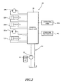
overload protector 40 is provided in themobile crane 1 to preventmobile crane 1 from being in a so-called overload state in which a load W1 acting on the front end of theboom 22 exceeds a rated load Wm according to the working conditions including the width of anoutrigger 12 in the lateral direction, the swivel angle of theswivel base 21, and a derricking angle θ and a telescopic length L of theboom 22. - As shown in
Fig. 3 , theoverload protector 40 has acontroller 41 constituted by a CPU, a ROM, a RAM and so forth. When thecontroller 41 receives an input signal from the devices connected to its input side, the CPU reads a program stored in the ROM based on the input signal, stores the state detected by the input signal in the RAM, and transmits an output signal to the devices connected to its output side. - As shown in
Fig. 3 , the following components are connected to the input side of the controller 41: anoperation input part 42 that is operated by the user to perform various settings for crane operation; a firstderricking angle detector 43, which is a means for detecting the derricking angle of the base end of thebottom boom member 22a; a secondderricking angle detector 44, which is a means for detecting the derricking angle of the front end of thetop boom member 22d; atelescopic length detector 45 that detects the telescopic length of theboom 22; aswivel angle detector 46 that detects the swivel angle of theboom 22; and aload detector 47 that detects the load W1 acting on the front end of theboom 22. - Meanwhile, as shown in
Fig. 3 , the following components are connected to the output side of the controller 41: acontrol valve unit 33, adisplay part 48 such as a liquid crystal display that can display a setting state or an actual state of theboom 22; and aspeaker 49 that sounds an error and gives an alarm. - The
controller 41 stores a table representing the relationship between the working radius R and the rated load Wm of theboom 22. Thecontroller 41 extracts the rated load Wm for the working radius R of theboom 22 from the table and calculates a load factor I that is a ratio of the actual load W1 acting on the front end of theboom 22 to the extracted rated load Wm (I=W1/Wm× 100(%)). When the load factor I is over 100%, thecontroller 41 displays the overload state on thedisplay part 48, sounds an alarm fromspeaker 49, and controls and restricts the crane operation. - The
controller 41 calculates the working radius R of theboom 22 based on the derricking angle θ and the telescopic length L of the boom 22 (R=Lcosθ). Since theboom 22 bends by its own weight, thecontroller 41 calculates the derricking angle θ, taking into consideration the flexure of theboom 22. - As shown in
Fig. 4 , the derricking angle θ is acquired by calculating a flexing angle α as the flexible volume of theboom 22 when an inflexible virtual boom 22' (indicated by the two-dot chain line shown inFig. 4 ) inclines such that the front end of the inflexible virtual boom 22' reaches the front end of the actual flexible boom 22 (the dashed-dotted line shown inFig. 4 ), and by subtracting the flexing angle α from a detected angle θ1 by the first derricking angle detector 43 (θ=θ1-α). - The flexing angle α of the
boom 22 can be acquired by two methods, a first flexing angle acquisition method (hereinafter "first method") as a first means for acquiring the flexible volume of theboom 22 and a second flexing angle acquisition method (hereinafter "second method") as a second means for acquiring the flexible volume of theboom 22. With the first method, the flexing angle α of theboom 22 is acquired based on the detected angle θ1 by the firstderricking angle detector 43 and a detected angle θ2 by the secondderricking angle detector 44. Meanwhile, with the second method, the flexing angle α of theboom 22 is acquired based on the detected angle θ1 by the firstderricking angle detector 43. - With the first method, the flexing angle α of the
boom 22 is calculated by multiplying the difference (θ1-θ2) between the detected angle θ1 by the firstderricking angle detector 43 and the detected angle θ2 by the secondderricking angle detector 44 by a coefficient K (α=K(θ1-θ2)). - Here, the coefficient K is a numeric value that is determined according to the telescopic length L of the
boom 22 and the telescopic patterns of theboom 22 obtained by combining the lengths of theboom members boom 22 is, the greater the flexing angle α is, so that the longer the telescopic length L of theboom 22 is, the greater the coefficient K is. Moreover, theboom 22 may have a plurality of telescopic patterns to have a predetermined telescopic length L, except the minimum telescopic length and the maximum telescopic length. For the same telescopic length L, the flexing angle α increases when a thinner boom member extends. Therefore, the coefficient K is greater in a telescopic pattern in which a boom member located in the front end side extends than in a telescopic pattern in which a boom member located in the base end side extends. This coefficient K is determined for each telescopic length L and each telescopic pattern of theboom 22, based on actual measurement or calculation. Thecontroller 41 stores a table representing the relationship between the coefficients K, and the telescopic lengths L and the telescopic patterns of theboom 22. - With the second method, the flexing angle α of the
boom 22 is acquired, which corresponds to the detected angle θ1 by the firstderricking angle detector 43, the detected length L by thetelescopic length detector 45, and the detected load by theload detector 47 is acquired, by using a table representing the relationship between the flexing angle α and the moment (theboom 22's own weight and the load of goods) acting around the base point from which theboom 22 performs derricking movement, for each condition (the telescopic length L and the derricking angle) of theboom 22 stored in thecontroller 41. - In the
mobile crane 1 as a work machine, which has the above-described configuration, thecontroller 41 of theoverload protector 40 determines whether or not the load W1 acting on the front end of theboom 22 exceeds the limit, and performs a process of operation control to control crane operation, as shown inFig. 5 . - In step S1, the CPU determines whether or not the first
derricking angle detector 43 is in the normal state. When determining that the firstderricking angle detector 43 is in the normal state, the CPU moves the step to step S2. On the other hand, when determining that firstderricking angle detector 43 is not in the normal state, the CPU moves the step to step S13. Here, the case in which the firstderricking angle detector 43 is not in the normal state is, for example, a case in which the signal wire of the firstderricking angle detector 43 is broken, and therefore the signal indicating the angle is not inputted, or a case in which the detected angle θ1 is out of a predetermined range of the angles due to the failure of the attachment of the firstderricking angle detector 43 or a bad condition of theboom member 22a, such as deformation. - When determining that the first
derricking angle detector 43 is in the normal condition in the step S1, the CPU determines whether or not the secondderricking angle detector 44 is in the normal condition in the step 2. When determining that the secondderricking angle detector 44 is in the normal condition, the CPU moves the step to step S3. On the other hand, when determining that the secondderricking angle detector 44 is not in the normal condition, the CPU moves the step to step S7. Here, the case in which the secondderricking angle detector 44 is not in the normal state is, for example, a case in which the signal wire of the secondderricking angle detector 44 is broken, and therefore the signal indicating the angle is not inputted, or a case in which the detected angle θ2 is out of a predetermined range of the angles due to the failure of the attachment of the secondderricking angle detector 44 or a bad condition of theboom member 22d, such as deformation. - When determining that the second
derricking angle detector 44 is in the normal state in the step S2, the CPU determines whether or not the difference (θ1-θ2) between the detected angle θ1 by the firstderricking angle detector 43 and the detected angle θ2 by the secondderricking angle detector 44 is within the range from a first predetermined value A1 (e.g. -10 degrees) to a second predetermined value A2 (e.g. 30 degrees) (A1≤θ1-θ2≤A2). When determining that θ1-θ2 is within A1≤θ1-θ2≤A2, the CPU moves the step to step S4. On the other hand, when determining that θ1-θ2 is not within A1≤θ1-θ2≤A2, the CPU moves the step to the step S13. Here, the case in which the difference (θ1-θ2) between the detected angle θ1 by the firstderricking angle detector 43 and the detected angle θ2 by the secondderricking angle detector 44 is within the range from the first predetermined value A1 to the second predetermined value A2 (A1≤θ1-θ2≤A2) means that the flexible volume of theboom 22 is normal (seeFig. 6 ). On the other hand, when the difference (θ1-θ2) between the detected angle θ1 by the firstderricking angle detector 43 and the detected angle θ2 by the secondderricking angle detector 44 is smaller than the first predetermined value A1 (Fig. 8 ), or greater than the second predetermined value A2 (Fig. 7 ), there are possibilities that a boom member is deformed or a bolt used to form a boom member is loosened. - When determining that the difference between the detected angle θ1 by the first
derricking angle detector 43 and the detected angle θ2 by the secondderricking angle detector 44 is within the range from the first predetermined value A1 to the second predetermined value A2 in the step S3, the CPU calculates the derricking angle θ of theboom 22 using the first method, and moves the step to step S5. - In the step S5, the CPU calculates the working radius R based on the derricking angle θ of the
boom 22, which is calculated in the step S4, and determines whether or not the load factor I for the calculated working radius is smaller than 100%. When determining that the load factor I is smaller than 100%, the CPU moves the step to step S6. On the other hand, when determining that theload factor 1 is not smaller than 100%, the CPU moves the step to step S11. - When determining that the load factor I is smaller than 100% in the step S5, the CPU determines that the crane is operated at a normal working speed and ends the process of operation control in the step S6.
- When determining that the second
derricking angle detector 44 is not in the normal condition in the step S2, the CPU calculates the derricking angle θ of theboom 22 using the second method in the step S7 and moves the step to step S8. - In the step S8, the CPU displays that the second
derricking angle detector 44 fails on thedisplay part 48, sounds an alarm from thespeaker 49, and moves the step to step S9. - In the step S9, the CPU calculates the working radius R based on the derricking angle θ of the
boom 22, which is calculated in the step S7, and determines whether or not the load factor I for the calculated working radius R is smaller than 100%. When determining that the load factor I is smaller than 100%, the CPU moves the step to step S10. On the other hand, when determining that the load factor I is not smaller than 100%, the CPU moves the step to the step S11. - When determining that the load factor is smaller than 100% in the step S9, the CPU reduces the working speed of the crane to a speed that is lower than the normal working speed, allows the crane to operate only in the direction in which the load factor I decreases in the step S10, and then ends the process of operation control. Here, the operation in the direction in which the load factor I decreases includes operation to increase the derricking angle of the
boom 22, operation to reduce the telescopic length of theboom 22, and operation to unreel thewire rope 23 of thewinch 24. - When determining that the load factor I is not smaller than 100% in the step S5, or when determining that the load factor I is not smaller than 100% in the step S9, the CPU displays the overload on the
display part 48, sounds an alarm from thespeaker 49, and then moves the step to step S12. - In the step S12, the CPU stops the crane operation and ends the process of operation control.
- When determining that the first
derricking angle detector 43 is not in the normal condition in the step S1, or when determining that θ1-θ2is not within the range from the first predetermined value A1 to the second predetermined value A2 in the step S3, the CPU displays that the crane cannot work in an error condition on thedisplay 48, sounds an alarm from thespeaker 49 in the step S13, and then moves the step to the step S12. - As described above, the work machine according to the present embodiment can switch between the first method of acquiring the flexing angle α of the
boom 22 based on the detected angle θ1 by the firstderricking angle detector 43 and the detected angle θ2 by the secondderricking angle detector 43, and second method of acquiring the flexing angle α of theboom 22 based on the detected angle θ1 by the firstderricking angle detector 43. By this means, even if the secondderricking angle detector 44 cannot detect the derricking angle θ2, it is possible to acquire the correct working radius R of theboom 22 based on the flexing angle α of theboom 22, which is acquired by the second method. Therefore, it is possible to continue the work safely and improve the working efficiency. - In addition, when the difference (θ1-θ2) between the detected angle θ1 by the first
derricking angle detector 43 and the detected angle θ2 by the secondderricking angle detector 44 is not within the range from the first predetermined value A1 to the second predetermined value A2 (A1≤θ1-θ2≤A2), the acquisition of the flexing angle α is restricted. By this means, it is possible to detect abnormal conditions, including deformation of theboom members derricking angle detector 43 or the secondderricking angle detector 44, based on the detected angle θ1 by the firstderricking angle detector 43 or the detected angle 62 by the secondderricking angle detector 44. Consequently, it is possible to improve the safety during the crane work. - Moreover, when the first
derricking angle detector 43 is in the normal condition, but the secondderricking angle detector 44 is not in the normal condition, it is possible to acquire the flexing angle α of theboom 22 by the second method. By this means, even if the first method is not available to acquire the flexing angle α of theboom 22 because the secondderricking angle detector 44 fails, the second method is available to acquire the flexing angle α instead. However, the first method normally has a priority to acquire the flexing angle α of theboom 22, and therefore it is possible to acquire a precise flexing angle α at normal times. - In addition, in the situation where the second method is available to acquire the flexing angle α of the
boom 22 instead of the first method, the flexing angle α of theboom 22 is automatically acquired by the second method. By this means, even if the first method is not available to acquire the flexing angle α of theboom 22, the second method is available to acquire the flexing angle α of theboom 22 instead to continue the crane operation. Consequently, it is possible to improve the working efficiency. - Moreover, when the first
derricking angle detector 43 is not in the normal condition, the acquisition of the flexing angle α of theboom 22 is restricted. By restricting the acquisition of the flexing angle α of theboom 22, therefore it is possible to stop the crane operation, and consequently improve the safety. -
Fig. 9 shows another embodiment of the present invention. - This
mobile crane 1 is configured to be able to switch to the second method of acquiring the flexing angle α of theboom 22 by the user who operates theoperation input part 42, when the CPU determines that the secondderricking angle detector 44 is not in the normal condition in the step 2 of the process of operation control in the above-described embodiment. - As shown in
Fig. 9 , when determining that the secondderricking angle detector 44 is not in the normal condition in the step S2, the CPU determines whether or not switching operation has been performed to change the method of acquiring the flexing angle in step S14. When determining that the switching operation has been performed to change the method of acquiring the flexing angle, the CPU moves the step to step S7. On the other hand, when determining that the switching operation has not been performed to change the method of acquiring the flexing angle, the CPU moves the step to step S13. - In this way, with the work machine according to the present embodiment, even if the second
derricking angle detector 44 cannot detect the derricking angle θ2, it is possible to acquire the correct working radius R of theboom 22 based on the flexing angle αof theboom 22, which is acquired by the second method in the same way in the above-described embodiment. Therefore, it is possible to continue the work safely, and consequently improve the working efficiency. - In addition, in the situation where the flexing angle α of the
boom 22 can be acquired by the second method, the user can select the second method. By this means, even if it is not possible to acquire the flexing angle α of theboom 22 by the first method, the second method can be selected by the user to acquire the flexing angle α of theboom 22. Therefore, it is possible to acquire the flexing angle α of theboom 22 by the second method after checking the condition of the boom, and consequently improve the safety. - Moreover, in the
mobile crane 1 according to the embodiments, thecontroller 41 of theoverload protector 40 performs error determination processing to determine whether or not the difference between the flexible volume acquired by the first method and the flexible volume acquired by the second method is within a predetermined range. - When determining that the difference between the flexible volume acquired by the first method and the flexible volume acquired by the second method is within a predetermined range, the
controller 41 performs the process of operation control. On the other hand, when determining that the difference between the flexible volume acquired by the first method and the flexible volume acquired by the second method is not within a predetermined range, thecontroller 41 displays that the firstderricking angle detector 43 or the secondderricking angle detector 44 fails, or theoverload detector 40 fails, on thedisplay part 48. - At this time, in order to allow only the operation to reduce the load factor, the
controller 41 may restrict the crane operation to the operation to increase the derricking angle of theboom 22, the operation to reduce the telescopic length of theboom 22, and the operation to unreel thewire rope 23 of thewinch 24. - In this way, the
controller 41 determines whether or not the difference between the flexible volume acquired by the first method and the flexible volume acquired by the second method is within a predetermined range. By this means, it is possible to detect the failure of the firstderricking angle detector 43 or the secondderricking angle detector 44, and the failure of theoverload protector 40, and therefore improve the safety. - Here, with the embodiments, a configuration has been described where the CPU determines whether or not the difference (θ1-θ2) between the detected angle θ1 by the first
derricking angle detector 43 and the detected angle θ2 by the secondderricking angle detector 44 is within the range from the first predetermined value A1 to the second predetermined value A2 (A1≤θ1-θ2≤A2), and, when θ1-θ2 is not within A1≤θ1-θ2≤A2, the CPU determines that the flexible volume of theboom 22 is abnormal. However, it is by no means limiting. For example, the range for which the CPU determines that the flexible volume of theboom 22 is abnormal may be calculated in advance, according to the derricking angle of theboom member 22a, the telescopic length L of theboom 22 and the load of goods. Alternatively, in order to determine the range for which the CPU determines that the flexible volume of theboom 22 is abnormal, the derricking angle of theboom member 22a, the telescopic length L of theboom 22 and the load of goods are actually measured and stored, and then used according to the condition of theboom 22. Particularly, for theboom 22 having the minimum telescopic length, it is possible to easily detect the flexible volume being abnormal by narrowing the range for which the CPU determines that the flexible volume of theboom 22 is abnormal. - In addition, with the embodiments, a configuration has been described where the
crane apparatus 20 has atelescopic boom 22. However, the present invention is applicable to a crane apparatus has a boom with a fixed length. In this case, it is not necessary to consider the telescopic length of the boom as a variable to acquire the flexing angle α and calculate the working radius R. - Moreover, with the embodiments, although a configuration has been described where the first
derricking angle detector 43 is provided on the base end of thebottom boom member 22a, and the secondderricking angle detector 44 is provided on the front end of thetop boom member 22d, this is by no means limiting. When an auxiliary jib is attached to the front end of the top boom member 2d of theboom 22, the flexing angle may be acquired by a derricking angle detector provided in the auxiliary jib, in addition to the derricking angle detector provided in theboom 22. For example, when the auxiliary jib can perform derricking movement with respect to theboom 22, the derricking angle detectors may be provided on the base end and the front end of the auxiliary jib, respectively, and therefore it is possible to acquire the respective flexing angles of theboom 22 and the auxiliary jib. Meanwhile, when the auxiliary jib is fixed to theboom 22, a derricking angle detector is provided on the front end of the auxiliary jib, and the flexing angle of the auxiliary jib may be acquired from thederricking angle detector 44 provided on the front end of theboom 22 and also the derricking angle detector provided on the auxiliary jib. - Moreover, with the above-described embodiments, a configuration has been described where the rated load Wm for the working radius R of the
boom 22 is acquiredi. However, the rated load Wm is changed depending on the position in which theboom 22 swivels with respect to thevehicle 10 as well as the working radius R of theboom 22, and therefore the rated load Wm for the working radius R at the position in which theboom 22 swivels may be acquired. - In addition, with the embodiments, although a configuration has been described where the present invention is applied to the
mobile crane 1, this is by no means limiting. The present invention is applicable to an aerial work platform having a boom provided with a bucket at the front end of the boom, as long as the boom can perform derricking movement. - Moreover, with the embodiments, the working speed of the crane is lower than the normal working speed, and the operation is allowed only in the direction in which the rated load I decreases, in the
step 10 of the process of operation control. However, it is by no means limiting. For example, the working speed may be reduced without restricting the direction in which the crane operates, or the direction in which the crane operates may be restricted without restricting the working speed of the crane.
Claims (9)
- A work machine (1) with a boom (22) that can be derricked, comprising:a first derricking angle detector (43) configured to detect a derricking angle of the boom (22) at a base end of the boom (22);a second derricking angle detector (44) configured to detect a derricking angle of the boom (22) at a front end of the boom (22);a first flexible volume acquisition part configured to acquire a flexible volume of the boom (22) based on a detected angle by the first derricking angle detector (43) and a detected angle by the second derricking angle detector (44); characterized in that the work machine (1) further comprises:a second flexible volume acquisition part configured to acquire a flexible volume of the boom (22) based on the detected angle by the first derricking angle detector (43); anda switching part configured to switch between acquisition of the flexible volume of the boom (22) by the first flexible volume acquisition part and acquisition of the flexible volume of the boom (22) by the second flexible volume acquisition part when the flexible volume of the boom (22) is acquired.
- The work machine (1) according to claim 1, further comprising:a first condition determination part configured to determine whether or not the first derricking angle detector (43) is in a normal condition, based on a result of detection by the first derricking angle detector (43);a second condition determination part configured to determine whether or not the second derricking angle detector (44) is in a normal condition, based on a result of detection by the second derricking angle detector (44);a first execution part configured to execute acquisition of the flexible volume of the boom (22) by the first flexible volume acquisition part, when the first condition determination part determines that the first derricking angle detector (43) is in the normal condition and the second condition determination part determines that the second derricking angle detector (44) is in the normal condition; anda first restriction part configured to restrict acquisition of the flexible volume of the boom (22) by the first flexible volume acquisition part when a difference between the detected angle by the first derricking angle detector (43) and the detected angle by the second derricking angle detector (44) is out of a predetermined range.
- The work machine (1) according to claim 2, further comprising a second allowing part configured to allow the second flexible volume acquisition part to acquire the flexible volume of the boom (22), when the first condition determination part determines that the first derricking angle detector (43) is in the normal condition but the second condition determination part determines that the second derricking angle detector (44) is not in the normal condition.
- The work machine (1) according to claim 3, further comprising a second execution part configured to execute acquisition of the flexible volume of the boom (22) by the second flexible volume acquisition part, when the second allowing part allows the second flexible volume acquisition part to acquire the flexible volume of the boom (22).
- The work machine according to claim 3, further comprising a second selecting part configured to allow the second flexible volume acquisition part to be selected to acquire the flexible volume of the boom (22), when the second allowing part allows the second flexible volume acquisition part to acquire the flexible volume of the boom (22).
- The work machine (1) according to one of claim 2 to claim 5, further comprising an acquisition restriction part configured to restrict acquisition of the flexible volume of the boom (22) when the first condition determination part determines that the first derricking angle detector (43) is not in the normal condition.
- The work machine (1) according to one of claim 1 to claim 6, wherein the first flexible volume acquisition part calculates the flexible volume of the boom (22) based on a relationship among a difference between a result of detection by the first derricking angle detector (43) and a result of detection by the second derricking angle detector (44), the derricking angle of the boom (22), and a length of the boom (22).
- The work machine (1) according to one of claim 1 to claim 7, wherein the second flexible volume acquisition part stores a moment acting around a base point from which the boom (22) performs derricking movement and a flexing angle, for each telescopic length and also for each derricking angle of the boom (22), and outputs the flexing angle based on a result of detection by the first derricking angle detector (43).
- The work machine (1) according to claim 1, further comprising an error determination part configured to determine whether or not a difference between the flexible volume acquired by the first flexible volume acquisition part and the flexible volume acquired by the second flexible volume acquisition part is within a predetermined range.
Applications Claiming Priority (1)
| Application Number | Priority Date | Filing Date | Title |
|---|---|---|---|
| JP2012068955A JP5889688B2 (en) | 2012-03-26 | 2012-03-26 | Work machine |
Publications (2)
| Publication Number | Publication Date |
|---|---|
| EP2644558A1 EP2644558A1 (en) | 2013-10-02 |
| EP2644558B1 true EP2644558B1 (en) | 2015-01-28 |
Family
ID=47891445
Family Applications (1)
| Application Number | Title | Priority Date | Filing Date |
|---|---|---|---|
| EP20130159018 Active EP2644558B1 (en) | 2012-03-26 | 2013-03-13 | Work machine with flexible boom |
Country Status (4)
| Country | Link |
|---|---|
| US (1) | US8768562B2 (en) |
| EP (1) | EP2644558B1 (en) |
| JP (1) | JP5889688B2 (en) |
| CN (1) | CN103359617B (en) |
Families Citing this family (15)
| Publication number | Priority date | Publication date | Assignee | Title |
|---|---|---|---|---|
| JP6121663B2 (en) * | 2012-07-10 | 2017-04-26 | 株式会社タダノ | Work vehicle |
| JP6147062B2 (en) * | 2013-04-02 | 2017-06-14 | 株式会社タダノ | Work condition check device for work equipment |
| JP6284302B2 (en) * | 2013-04-02 | 2018-02-28 | 株式会社タダノ | Boom telescopic pattern selection device |
| CA155199S (en) * | 2013-08-21 | 2014-11-03 | Tadano Ltd | Outrigger for a crane truck |
| CN104692250B (en) * | 2015-02-05 | 2016-11-02 | 三一汽车起重机械有限公司 | Crane and torgue measurement System and method for thereof |
| DE102016103573B4 (en) * | 2015-03-02 | 2021-04-22 | Kabushiki Kaisha Kobe Seiko Sho (Kobe Steel, Ltd.) | CRANE |
| DE102015108473A1 (en) * | 2015-05-28 | 2016-12-01 | Schwing Gmbh | Large manipulator with quick folding and unfolding articulated mast |
| JP2017082733A (en) * | 2015-10-30 | 2017-05-18 | 株式会社タダノ | Work machine and engine stop control device |
| JP2017082734A (en) * | 2015-10-30 | 2017-05-18 | 株式会社タダノ | Work vehicle |
| DE102017125715A1 (en) * | 2016-11-09 | 2018-05-09 | Liebherr-Werk Biberach Gmbh | Device for compensation of diagonal tension in cranes |
| US9818287B1 (en) * | 2016-11-09 | 2017-11-14 | Altec Industries, Inc. | Load-indicative alarm |
| US10457531B2 (en) * | 2016-11-30 | 2019-10-29 | Ningbo China Winch Co., Ltd. | Winch and safety device thereof |
| CN106829754B (en) * | 2017-03-24 | 2018-05-22 | 徐州海伦哲专用车辆股份有限公司 | A kind of insulating overhead operating vehicle and its automatic amplitude limit method of insulated working platform |
| CN107352402B (en) * | 2017-09-21 | 2018-08-03 | 上海上安机械施工有限公司 | A kind of arm fracture active protecting device |
| JP7113735B2 (en) * | 2018-12-21 | 2022-08-05 | 住友重機械建機クレーン株式会社 | mobile crane |
Family Cites Families (14)
| Publication number | Priority date | Publication date | Assignee | Title |
|---|---|---|---|---|
| US3586841A (en) * | 1969-02-14 | 1971-06-22 | Warner Swasey Co | Boom load indicating system |
| US4057792A (en) * | 1970-01-21 | 1977-11-08 | Ludwig Pietzsch | Overload safety device for telescopic cranes |
| JPS5339504Y2 (en) * | 1974-03-05 | 1978-09-25 | ||
| FI801541A (en) * | 1979-05-18 | 1980-11-19 | Coles Cranes Ltd | SAW LOAD INDICATOR FOER LAST |
| GB2050294B (en) * | 1979-05-18 | 1983-04-07 | Coles Cranes Ltd | Safe load indicator |
| JPH07125987A (en) * | 1993-11-08 | 1995-05-16 | Komatsu Mec Corp | Suspension load/overturning moment detecting device for mobile crane |
| JPH08282977A (en) * | 1995-04-14 | 1996-10-29 | Kobe Steel Ltd | Method and device for detecting work radius of crane |
| JPH11263583A (en) * | 1998-03-17 | 1999-09-28 | Tadano Ltd | Load shake preventing device at starting lift of hoisted cargo by crane |
| JP4683686B2 (en) * | 2000-02-28 | 2011-05-18 | 株式会社タダノ | Method and apparatus for calculating deflection angle of boom work vehicle |
| JP4744664B2 (en) * | 2000-03-08 | 2011-08-10 | 株式会社タダノ | Control device for working machine with boom |
| JP5019770B2 (en) * | 2006-03-27 | 2012-09-05 | 株式会社タダノ | Crane hook block deflection angle detector |
| FI122429B (en) * | 2008-12-29 | 2012-01-31 | Bronto Skylift Oy Ab | Method for measuring the bend of a ski lift boom, ski lift and measuring system |
| CN201506691U (en) * | 2009-09-27 | 2010-06-16 | 徐州重型机械有限公司 | Engineering machinery and metering equipment used for metering working range of cantilever crane |
| JP5711586B2 (en) * | 2011-03-31 | 2015-05-07 | 株式会社タダノ | Method and apparatus for setting boom deflection control device in working machine with telescopic boom |
-
2012
- 2012-03-26 JP JP2012068955A patent/JP5889688B2/en active Active
-
2013
- 2013-03-13 EP EP20130159018 patent/EP2644558B1/en active Active
- 2013-03-14 US US13/803,853 patent/US8768562B2/en active Active
- 2013-03-21 CN CN201310091116.6A patent/CN103359617B/en active Active
Also Published As
| Publication number | Publication date |
|---|---|
| JP2013199349A (en) | 2013-10-03 |
| EP2644558A1 (en) | 2013-10-02 |
| US8768562B2 (en) | 2014-07-01 |
| CN103359617A (en) | 2013-10-23 |
| JP5889688B2 (en) | 2016-03-22 |
| CN103359617B (en) | 2015-04-22 |
| US20130253759A1 (en) | 2013-09-26 |
Similar Documents
| Publication | Publication Date | Title |
|---|---|---|
| EP2644558B1 (en) | Work machine with flexible boom | |
| US10597266B2 (en) | Crane and method for monitoring the overload protection of such a crane | |
| EP3147252B1 (en) | Automatic boom telescopic motion apparatus for working machine | |
| US10865080B2 (en) | Overload preventing device | |
| US11905144B2 (en) | Control of a handling machine | |
| US10919739B2 (en) | Overload preventing device | |
| JP6747633B1 (en) | Crane device, hanging number determination method and program | |
| JP5543741B2 (en) | Crane overturn prevention device | |
| EP3360840B1 (en) | Operating machine | |
| JP7167618B2 (en) | Lateral pulling detection device and crane | |
| RU2440924C1 (en) | Method of crane operation control | |
| EP3805142B1 (en) | Mobile crane | |
| CN111747311B (en) | Crane with a movable crane | |
| JP6984174B2 (en) | crane | |
| WO2021127058A1 (en) | System and method for monitoring crane and crane having the same | |
| JP2008094623A (en) | Safety device for mobile crane | |
| JP2014069914A (en) | Extension state monitoring device for outrigger jack | |
| JP6531527B2 (en) | Mobile crane operation switching device | |
| JP6923848B2 (en) | Wire rope hook number determination device and mobile crane | |
| JP7067377B2 (en) | Work machine load display device | |
| JP7467836B2 (en) | Mobile Crane | |
| EP3925919A1 (en) | Lifting control device and mobile crane | |
| JP2017024872A (en) | Detection device for hook block | |
| US20210171322A1 (en) | Mobile crane | |
| JP6527092B2 (en) | crane |
Legal Events
| Date | Code | Title | Description |
|---|---|---|---|
| PUAI | Public reference made under article 153(3) epc to a published international application that has entered the european phase |
Free format text: ORIGINAL CODE: 0009012 |
|
| 17P | Request for examination filed |
Effective date: 20130313 |
|
| AK | Designated contracting states |
Kind code of ref document: A1 Designated state(s): AL AT BE BG CH CY CZ DE DK EE ES FI FR GB GR HR HU IE IS IT LI LT LU LV MC MK MT NL NO PL PT RO RS SE SI SK SM TR |
|
| AX | Request for extension of the european patent |
Extension state: BA ME |
|
| RBV | Designated contracting states (corrected) |
Designated state(s): AL AT BE BG CH CY CZ DE DK EE ES FI FR GB GR HR HU IE IS IT LI LT LU LV MC MK MT NL NO PL PT RO RS SE SI SK SM TR |
|
| REG | Reference to a national code |
Ref country code: DE Ref legal event code: R079 Ref document number: 602013000909 Country of ref document: DE Free format text: PREVIOUS MAIN CLASS: B66C0023900000 Ipc: B66C0013160000 |
|
| GRAP | Despatch of communication of intention to grant a patent |
Free format text: ORIGINAL CODE: EPIDOSNIGR1 |
|
| RIC1 | Information provided on ipc code assigned before grant |
Ipc: B66C 13/16 20060101AFI20140709BHEP Ipc: B66F 11/04 20060101ALI20140709BHEP Ipc: B66C 23/90 20060101ALI20140709BHEP |
|
| INTG | Intention to grant announced |
Effective date: 20140806 |
|
| GRAS | Grant fee paid |
Free format text: ORIGINAL CODE: EPIDOSNIGR3 |
|
| GRAA | (expected) grant |
Free format text: ORIGINAL CODE: 0009210 |
|
| AK | Designated contracting states |
Kind code of ref document: B1 Designated state(s): AL AT BE BG CH CY CZ DE DK EE ES FI FR GB GR HR HU IE IS IT LI LT LU LV MC MK MT NL NO PL PT RO RS SE SI SK SM TR |
|
| REG | Reference to a national code |
Ref country code: GB Ref legal event code: FG4D |
|
| REG | Reference to a national code |
Ref country code: CH Ref legal event code: EP |
|
| REG | Reference to a national code |
Ref country code: IE Ref legal event code: FG4D |
|
| REG | Reference to a national code |
Ref country code: DE Ref legal event code: R096 Ref document number: 602013000909 Country of ref document: DE Effective date: 20150312 |
|
| REG | Reference to a national code |
Ref country code: AT Ref legal event code: REF Ref document number: 708151 Country of ref document: AT Kind code of ref document: T Effective date: 20150315 |
|
| REG | Reference to a national code |
Ref country code: AT Ref legal event code: MK05 Ref document number: 708151 Country of ref document: AT Kind code of ref document: T Effective date: 20150128 |
|
| REG | Reference to a national code |
Ref country code: NL Ref legal event code: VDEP Effective date: 20150128 |
|
| REG | Reference to a national code |
Ref country code: LT Ref legal event code: MG4D |
|
| PG25 | Lapsed in a contracting state [announced via postgrant information from national office to epo] |
Ref country code: FI Free format text: LAPSE BECAUSE OF FAILURE TO SUBMIT A TRANSLATION OF THE DESCRIPTION OR TO PAY THE FEE WITHIN THE PRESCRIBED TIME-LIMIT Effective date: 20150128 Ref country code: LT Free format text: LAPSE BECAUSE OF FAILURE TO SUBMIT A TRANSLATION OF THE DESCRIPTION OR TO PAY THE FEE WITHIN THE PRESCRIBED TIME-LIMIT Effective date: 20150128 Ref country code: HR Free format text: LAPSE BECAUSE OF FAILURE TO SUBMIT A TRANSLATION OF THE DESCRIPTION OR TO PAY THE FEE WITHIN THE PRESCRIBED TIME-LIMIT Effective date: 20150128 Ref country code: NO Free format text: LAPSE BECAUSE OF FAILURE TO SUBMIT A TRANSLATION OF THE DESCRIPTION OR TO PAY THE FEE WITHIN THE PRESCRIBED TIME-LIMIT Effective date: 20150428 Ref country code: BG Free format text: LAPSE BECAUSE OF FAILURE TO SUBMIT A TRANSLATION OF THE DESCRIPTION OR TO PAY THE FEE WITHIN THE PRESCRIBED TIME-LIMIT Effective date: 20150428 Ref country code: SE Free format text: LAPSE BECAUSE OF FAILURE TO SUBMIT A TRANSLATION OF THE DESCRIPTION OR TO PAY THE FEE WITHIN THE PRESCRIBED TIME-LIMIT Effective date: 20150128 Ref country code: ES Free format text: LAPSE BECAUSE OF FAILURE TO SUBMIT A TRANSLATION OF THE DESCRIPTION OR TO PAY THE FEE WITHIN THE PRESCRIBED TIME-LIMIT Effective date: 20150128 |
|
| PG25 | Lapsed in a contracting state [announced via postgrant information from national office to epo] |
Ref country code: IS Free format text: LAPSE BECAUSE OF FAILURE TO SUBMIT A TRANSLATION OF THE DESCRIPTION OR TO PAY THE FEE WITHIN THE PRESCRIBED TIME-LIMIT Effective date: 20150528 Ref country code: PL Free format text: LAPSE BECAUSE OF FAILURE TO SUBMIT A TRANSLATION OF THE DESCRIPTION OR TO PAY THE FEE WITHIN THE PRESCRIBED TIME-LIMIT Effective date: 20150128 Ref country code: RS Free format text: LAPSE BECAUSE OF FAILURE TO SUBMIT A TRANSLATION OF THE DESCRIPTION OR TO PAY THE FEE WITHIN THE PRESCRIBED TIME-LIMIT Effective date: 20150128 Ref country code: GR Free format text: LAPSE BECAUSE OF FAILURE TO SUBMIT A TRANSLATION OF THE DESCRIPTION OR TO PAY THE FEE WITHIN THE PRESCRIBED TIME-LIMIT Effective date: 20150429 Ref country code: AT Free format text: LAPSE BECAUSE OF FAILURE TO SUBMIT A TRANSLATION OF THE DESCRIPTION OR TO PAY THE FEE WITHIN THE PRESCRIBED TIME-LIMIT Effective date: 20150128 Ref country code: LV Free format text: LAPSE BECAUSE OF FAILURE TO SUBMIT A TRANSLATION OF THE DESCRIPTION OR TO PAY THE FEE WITHIN THE PRESCRIBED TIME-LIMIT Effective date: 20150128 Ref country code: NL Free format text: LAPSE BECAUSE OF FAILURE TO SUBMIT A TRANSLATION OF THE DESCRIPTION OR TO PAY THE FEE WITHIN THE PRESCRIBED TIME-LIMIT Effective date: 20150128 |
|
| REG | Reference to a national code |
Ref country code: DE Ref legal event code: R097 Ref document number: 602013000909 Country of ref document: DE |
|
| PG25 | Lapsed in a contracting state [announced via postgrant information from national office to epo] |
Ref country code: RO Free format text: LAPSE BECAUSE OF FAILURE TO SUBMIT A TRANSLATION OF THE DESCRIPTION OR TO PAY THE FEE WITHIN THE PRESCRIBED TIME-LIMIT Effective date: 20150128 Ref country code: SK Free format text: LAPSE BECAUSE OF FAILURE TO SUBMIT A TRANSLATION OF THE DESCRIPTION OR TO PAY THE FEE WITHIN THE PRESCRIBED TIME-LIMIT Effective date: 20150128 Ref country code: CZ Free format text: LAPSE BECAUSE OF FAILURE TO SUBMIT A TRANSLATION OF THE DESCRIPTION OR TO PAY THE FEE WITHIN THE PRESCRIBED TIME-LIMIT Effective date: 20150128 Ref country code: DK Free format text: LAPSE BECAUSE OF FAILURE TO SUBMIT A TRANSLATION OF THE DESCRIPTION OR TO PAY THE FEE WITHIN THE PRESCRIBED TIME-LIMIT Effective date: 20150128 Ref country code: MC Free format text: LAPSE BECAUSE OF FAILURE TO SUBMIT A TRANSLATION OF THE DESCRIPTION OR TO PAY THE FEE WITHIN THE PRESCRIBED TIME-LIMIT Effective date: 20150128 Ref country code: LU Free format text: LAPSE BECAUSE OF FAILURE TO SUBMIT A TRANSLATION OF THE DESCRIPTION OR TO PAY THE FEE WITHIN THE PRESCRIBED TIME-LIMIT Effective date: 20150313 Ref country code: EE Free format text: LAPSE BECAUSE OF FAILURE TO SUBMIT A TRANSLATION OF THE DESCRIPTION OR TO PAY THE FEE WITHIN THE PRESCRIBED TIME-LIMIT Effective date: 20150128 |
|
| PLBE | No opposition filed within time limit |
Free format text: ORIGINAL CODE: 0009261 |
|
| STAA | Information on the status of an ep patent application or granted ep patent |
Free format text: STATUS: NO OPPOSITION FILED WITHIN TIME LIMIT |
|
| PG25 | Lapsed in a contracting state [announced via postgrant information from national office to epo] |
Ref country code: IT Free format text: LAPSE BECAUSE OF FAILURE TO SUBMIT A TRANSLATION OF THE DESCRIPTION OR TO PAY THE FEE WITHIN THE PRESCRIBED TIME-LIMIT Effective date: 20150128 |
|
| REG | Reference to a national code |
Ref country code: FR Ref legal event code: ST Effective date: 20151130 |
|
| 26N | No opposition filed |
Effective date: 20151029 |
|
| REG | Reference to a national code |
Ref country code: IE Ref legal event code: MM4A |
|
| PG25 | Lapsed in a contracting state [announced via postgrant information from national office to epo] |
Ref country code: IE Free format text: LAPSE BECAUSE OF NON-PAYMENT OF DUE FEES Effective date: 20150313 |
|
| PG25 | Lapsed in a contracting state [announced via postgrant information from national office to epo] |
Ref country code: SI Free format text: LAPSE BECAUSE OF FAILURE TO SUBMIT A TRANSLATION OF THE DESCRIPTION OR TO PAY THE FEE WITHIN THE PRESCRIBED TIME-LIMIT Effective date: 20150128 Ref country code: FR Free format text: LAPSE BECAUSE OF NON-PAYMENT OF DUE FEES Effective date: 20150331 |
|
| PG25 | Lapsed in a contracting state [announced via postgrant information from national office to epo] |
Ref country code: BE Free format text: LAPSE BECAUSE OF FAILURE TO SUBMIT A TRANSLATION OF THE DESCRIPTION OR TO PAY THE FEE WITHIN THE PRESCRIBED TIME-LIMIT Effective date: 20150128 |
|
| REG | Reference to a national code |
Ref country code: CH Ref legal event code: PL |
|
| PG25 | Lapsed in a contracting state [announced via postgrant information from national office to epo] |
Ref country code: MT Free format text: LAPSE BECAUSE OF FAILURE TO SUBMIT A TRANSLATION OF THE DESCRIPTION OR TO PAY THE FEE WITHIN THE PRESCRIBED TIME-LIMIT Effective date: 20150128 |
|
| PG25 | Lapsed in a contracting state [announced via postgrant information from national office to epo] |
Ref country code: LI Free format text: LAPSE BECAUSE OF NON-PAYMENT OF DUE FEES Effective date: 20160331 Ref country code: CH Free format text: LAPSE BECAUSE OF NON-PAYMENT OF DUE FEES Effective date: 20160331 |
|
| PG25 | Lapsed in a contracting state [announced via postgrant information from national office to epo] |
Ref country code: HU Free format text: LAPSE BECAUSE OF FAILURE TO SUBMIT A TRANSLATION OF THE DESCRIPTION OR TO PAY THE FEE WITHIN THE PRESCRIBED TIME-LIMIT; INVALID AB INITIO Effective date: 20130313 |
|
| PG25 | Lapsed in a contracting state [announced via postgrant information from national office to epo] |
Ref country code: CY Free format text: LAPSE BECAUSE OF FAILURE TO SUBMIT A TRANSLATION OF THE DESCRIPTION OR TO PAY THE FEE WITHIN THE PRESCRIBED TIME-LIMIT Effective date: 20150128 |
|
| PG25 | Lapsed in a contracting state [announced via postgrant information from national office to epo] |
Ref country code: TR Free format text: LAPSE BECAUSE OF FAILURE TO SUBMIT A TRANSLATION OF THE DESCRIPTION OR TO PAY THE FEE WITHIN THE PRESCRIBED TIME-LIMIT Effective date: 20150128 |
|
| GBPC | Gb: european patent ceased through non-payment of renewal fee |
Effective date: 20170313 |
|
| PG25 | Lapsed in a contracting state [announced via postgrant information from national office to epo] |
Ref country code: GB Free format text: LAPSE BECAUSE OF NON-PAYMENT OF DUE FEES Effective date: 20170313 |
|
| PG25 | Lapsed in a contracting state [announced via postgrant information from national office to epo] |
Ref country code: SM Free format text: LAPSE BECAUSE OF FAILURE TO SUBMIT A TRANSLATION OF THE DESCRIPTION OR TO PAY THE FEE WITHIN THE PRESCRIBED TIME-LIMIT Effective date: 20150128 |
|
| PG25 | Lapsed in a contracting state [announced via postgrant information from national office to epo] |
Ref country code: PT Free format text: LAPSE BECAUSE OF FAILURE TO SUBMIT A TRANSLATION OF THE DESCRIPTION OR TO PAY THE FEE WITHIN THE PRESCRIBED TIME-LIMIT Effective date: 20150128 Ref country code: MK Free format text: LAPSE BECAUSE OF FAILURE TO SUBMIT A TRANSLATION OF THE DESCRIPTION OR TO PAY THE FEE WITHIN THE PRESCRIBED TIME-LIMIT Effective date: 20150128 |
|
| PG25 | Lapsed in a contracting state [announced via postgrant information from national office to epo] |
Ref country code: AL Free format text: LAPSE BECAUSE OF FAILURE TO SUBMIT A TRANSLATION OF THE DESCRIPTION OR TO PAY THE FEE WITHIN THE PRESCRIBED TIME-LIMIT Effective date: 20150128 |
|
| PGFP | Annual fee paid to national office [announced via postgrant information from national office to epo] |
Ref country code: DE Payment date: 20230321 Year of fee payment: 11 |