EP2644408B1 - Tread profile of a vehicle tyre - Google Patents
Tread profile of a vehicle tyre Download PDFInfo
- Publication number
- EP2644408B1 EP2644408B1 EP20130155045 EP13155045A EP2644408B1 EP 2644408 B1 EP2644408 B1 EP 2644408B1 EP 20130155045 EP20130155045 EP 20130155045 EP 13155045 A EP13155045 A EP 13155045A EP 2644408 B1 EP2644408 B1 EP 2644408B1
- Authority
- EP
- European Patent Office
- Prior art keywords
- extent
- shaped
- features
- radially
- height
- Prior art date
- Legal status (The legal status is an assumption and is not a legal conclusion. Google has not performed a legal analysis and makes no representation as to the accuracy of the status listed.)
- Active
Links
- 230000015572 biosynthetic process Effects 0.000 description 14
- 101100334009 Caenorhabditis elegans rib-2 gene Proteins 0.000 description 12
- XLYOFNOQVPJJNP-UHFFFAOYSA-N water Substances O XLYOFNOQVPJJNP-UHFFFAOYSA-N 0.000 description 9
- 239000000463 material Substances 0.000 description 7
- 238000005299 abrasion Methods 0.000 description 6
- 230000000694 effects Effects 0.000 description 6
- 239000011800 void material Substances 0.000 description 6
- 230000002093 peripheral effect Effects 0.000 description 5
- 230000035515 penetration Effects 0.000 description 3
- 238000005452 bending Methods 0.000 description 2
- 238000005096 rolling process Methods 0.000 description 2
- 238000010521 absorption reaction Methods 0.000 description 1
- 230000002411 adverse Effects 0.000 description 1
- 238000007599 discharging Methods 0.000 description 1
- 238000005457 optimization Methods 0.000 description 1
- 230000001681 protective effect Effects 0.000 description 1
- 230000003014 reinforcing effect Effects 0.000 description 1
- 239000012779 reinforcing material Substances 0.000 description 1
- 239000000758 substrate Substances 0.000 description 1
Images
Classifications
-
- B—PERFORMING OPERATIONS; TRANSPORTING
- B60—VEHICLES IN GENERAL
- B60C—VEHICLE TYRES; TYRE INFLATION; TYRE CHANGING; CONNECTING VALVES TO INFLATABLE ELASTIC BODIES IN GENERAL; DEVICES OR ARRANGEMENTS RELATED TO TYRES
- B60C11/00—Tyre tread bands; Tread patterns; Anti-skid inserts
- B60C11/03—Tread patterns
- B60C11/12—Tread patterns characterised by the use of narrow slits or incisions, e.g. sipes
- B60C11/1272—Width of the sipe
- B60C11/1281—Width of the sipe different within the same sipe, i.e. enlarged width portion at sipe bottom or along its length
-
- B—PERFORMING OPERATIONS; TRANSPORTING
- B60—VEHICLES IN GENERAL
- B60C—VEHICLE TYRES; TYRE INFLATION; TYRE CHANGING; CONNECTING VALVES TO INFLATABLE ELASTIC BODIES IN GENERAL; DEVICES OR ARRANGEMENTS RELATED TO TYRES
- B60C11/00—Tyre tread bands; Tread patterns; Anti-skid inserts
- B60C11/03—Tread patterns
- B60C11/12—Tread patterns characterised by the use of narrow slits or incisions, e.g. sipes
- B60C11/1204—Tread patterns characterised by the use of narrow slits or incisions, e.g. sipes with special shape of the sipe
- B60C2011/1209—Tread patterns characterised by the use of narrow slits or incisions, e.g. sipes with special shape of the sipe straight at the tread surface
Definitions
- the invention relates to a tread pattern of a pneumatic vehicle tire - in particular for commercial vehicles - with radially raised, spaced apart by grooves profile elements with narrow line or groove-shaped depressions in one or more profile elements, each aligned with their main extension direction component in the axial direction A of the pneumatic vehicle tire by the respective Extending profile member and open into the profile element limiting grooves, wherein one or more narrow line- or groove-shaped recesses in the radial direction R with a radially inner extension portion of the extension height T 2 and a radially outer extension region of the extension height T 1 are formed in the tire, wherein the radially inner extension portion in the radial direction R from the lowest point of the recess bottom to the radially outer extension portion and the radially outer extension portion of the radially inner Ers
- the groove-shaped recess in the radially outer extension region is formed as a sipe with a cutting width D and in the radially inner extension region as a tubular opening channel with a maximum
- Tread strips for vehicle tires are usually formed by grooves spaced, radially raised profile elements.
- the grooves allow void (negative portion of the profile) to absorb water and drain the water from the tread pattern.
- the profile elements form with their flanks formed by the grooves additional grip edges to handle on wet surface.
- the radially raised profile elements In a new tire, in which the radially raised profile elements still have their full profile depth, form the grooves with their reaching over the full profile depth groove depth on a large volume for the discharge of water.
- the profile elements are still flexible due to their full profile depth training.
- the profile elements are in acting traction and handling forces due to the deformation caused thereby only with a part of their radially outwardly acting surface in full-acting grip contact with the road surface, which are negatively affected especially wet grip properties. So that wet grip properties are not reduced too much in the new tire, the radially raised profile elements in the axial direction A and in the circumferential direction U of the tire are dimensioned relatively large, in order to obtain in this way a relatively large theoretically acting radially outer surface in contact with the road can come. This limits the negative impact of bending the surface. In order to improve the wet grip effect, fine incisions are occasionally formed in the profile elements which, when optimized, allow a significantly improved grip effect on wet surfaces without greater additional flexibility
- the tread depth of the tread pattern is increasingly reduced due to abrasion.
- the remaining profile elements are stiffer with their reduced profile depth, whereby the profile elements in the radial direction outwardly limiting surface are subject to less deformation and allow an improved wet grip.
- the volume of the remaining grooves in the tire tread which also reduces the ability to drain water from the tire tread and increases the risk of aquaplaning.
- additional grooves in the tread allows an additional volume for the later life cycle and thus in the later life cycle, a reduction of Aquaplaninggefahr.
- the additional grooves cause in new tires an additional reduction of the acting road contact surface due to the larger negative portion of the profile and beyond additional flexibility of the already very flexible profile elements, whereby bending effects of the profile elements and thereby conditional on passing with the road surface in contact tire surface is further reduced. This further reduces the wet grip suitability of new tires.
- the recess bottom of the channel-shaped flow opening is formed deep as possible in the profile.
- the visually recognizable depth of the groove bottom is also a sign to the user of the tire of the actual, usable groove depth.
- a large depth of the groove bottom in such designs to the fact that the remaining material thickness of the rubber material between the belt and the passage is only made correspondingly small, whereby their resistance to penetration of foreign bodies is limited during this last life cycle with an open passageway. If the groove bottom of the through-channel is formed at a shallower depth in the profile, the remaining mass of rubber material is increased, and thus the resistance to the penetration of a foreign body into the tire. But it also gives the user the impression as if the tire is no longer usable due to the small remaining groove depth after opening the through-channel, although the main grooves still have sufficient tread depth for further use.
- the invention is therefore based on the object with simple means to create a tread pattern, in which good abrasion and good rolling resistance good drainage and traction properties over the life cycle of the tire away when new and in the later life cycle with reduced abrasion profile depth despite good resistance against foreign bodies as long as possible made possible and made recognizable.
- a tread pattern of a pneumatic vehicle tire especially for commercial vehicles - with radially raised, spaced apart by grooves profile elements with narrow line or groove-shaped Recesses in one or more profile elements, each aligned with its main extension direction component in the axial direction A of the pneumatic vehicle tire extending through the respective profile element and open into the profile element limiting grooves, wherein one or more narrow line or groove-shaped recesses in the radial direction R with a radially inner extension portion of the extension height T 2 and a radially outer extension region of the extension height T 1 are formed in the tire, wherein the radially inner extension portion in the radial direction R from the lowest point of the recess bottom to the radially outer extension region and the radially outer extension region of the radially inner extension region to which the profile element extends radially outwardly bounding surface forming the ground contact surface, and wherein the groove-shaped recess in the radially outer extension region as Feinein is formed with a cutting
- the commercial vehicle tire can be formed with substantially circumferentially rigid profile elements in new condition, which have sufficient circumferential rigidity to achieve good Abriebeigenschaften and good rolling resistance, and yet still after abrasion of the tread pattern to the opening of the passage additional Void (negative proportion profile), thereby at least partially compensating the void loss of the other main grooves of the tire and thus providing a large void for receiving and draining the water over a long tire life.
- the formation of the passage opening with the dome-shaped radial elevations also allows a deep formation of the groove bottom, which is recognizable to the user as a deep groove and thus clearly indicates that additional void for receiving and discharging the water is available and the tire still has sufficient residual tread depth.
- the dome-shaped elevations still allow the provision of significantly reinforcing material increases the groove bottom, which provide additional protection of the groove bottom.
- the dome shape is particularly insensitive to damage and unwanted abrasion of the protective survey.
- the dome-shaped elevations allow by their height, width and shape thus reinforcing the groove bottom itself and at the same time a protection against the risk of penetration of foreign bodies and also reduce the risk of intrusion, since they facilitate the ejection of already partially invaded stones in the profile ,
- the fürwalkiolo the additional groove formed after opening the through-groove and then limited by her profile elements during unrolling is largely unaffected by the dome-shaped elevations. Unrolling and other performance characteristics are thus not adversely affected.
- a tread pattern according to the features of claim 2 wherein the dome-shaped elevations are formed in their cutting planes along their radial extent from its apex to the recess bottom with circular, oval or elliptical sectional contour lines. This can be made possible in a simple manner, a very robust training with well flow around, edgeless elevations.
- a tread pattern according to the features of claim 4 in which the dome-shaped elevations with a measured from the recess bottom to the apex of the dome-shaped elevation in the radial direction R of the tire maximum extent height h 1 with 1,5mm ⁇ h 1 ⁇ 3mm are formed.
- This can be achieved in a simple manner, an optimal compromise of high, desired robustness with low volume and material use for the surveys and remaining, structurally unaffected by the surveys groove bottom.
- a tread pattern according to the features of claim 5, wherein the dome-shaped elevations with a measured in the well base measured in the direction of extension of the recessed ground maximum extension length B 1 with B 2mm ⁇ 1 ⁇ 6 mm are formed.
- This can be achieved in a simple manner, an optimization of high, desired robustness with low volume and material usage for the surveys on the one hand and from remaining, structurally uninfluenced by the surveys groove bottom.
- a tread pattern according to the features of claim 11, wherein the pneumatic vehicle tire is a traction tire for commercial vehicles.
- the effect of the linear or groove-shaped depressions and formed in the groove bottom of the passageway surveys in the tire can be optimally used.
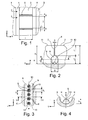
- FIGS. 1 to 4 show a section of a tread pattern of a pneumatic vehicle tire for commercial vehicles.
- the commercial vehicle tire is a commercial vehicle tire of a traction tire which is used on the drive axle of a utility vehicle.
- the tread pattern in a known manner within the ground contact surface extending over the entire circumference of the pneumatic vehicle tire aligned circumferentially aligned and adjacent in the axial direction A circumferential grooves 4 and three and also circumferentially aligned in the circumferential direction U and extending over the entire circumference circumferential ribs 1,2 and 3, of which the circumferential rib 2 in the axial direction A of the circumferential grooves 4 and 5, the circumferential rib 1 in the axial direction A of the circumferential groove 4 and the circumferential rib 3 in the axial direction A of the circumferential groove 5 is axially limited.
- Fig. 2 can be seen extending the circumferential ribs 1,2 and 3 thereby in the radial direction R from the groove bottom of the circumferential grooves 4 and 5 to the circumferential ribs 1,2 and 3 respectively radially outwardly limiting, the road contact surface forming shell surface 11 on a measured in the radial direction R extent P T , which indicates the tread depth in the region of the circumferential grooves 4 and 5 on the new tire.
- the circumferential rib 2 is distributed over the circumference of the pneumatic vehicle tire respectively provided with incisions 6 which extend in the axial direction A respectively through the entire extension width L of the circumferential rib 2, the incisions 6 on the one axial boundary side of the circumferential rib 2 in the circumferential groove 4 and on the other axial boundary side of the circumferential rib 2 open into the circumferential groove 5.
- the incisions 6 extend in the radial direction R - as in FIG. 2 to be recognized - via a measured in the radial direction R extension depth T with 10mm ⁇ T ⁇ 25mm starting from the radially outer, the peripheral rib 2 outwardly bounding lateral surface 11 up to the recess 6 radially inwardly limiting Recess bottom 9.
- the incisions 6 are each formed in their radially outer extension portion as a sipe 7 with the incision width D and in its radially inner extension portion as a tubular passageway or flow channel 8 of the tube width B.
- the sipe 7 extends, starting from the radially outer, the circumferential rib 1 outwardly bounding shell surface 11 via a radial extent T 1 radially inward.
- the radial extension region of the passage channel 8 begins, which extends in the radial direction R over an extent dimension T 2 inwards to the recess base 9, which defines the passage channel 8 radially inward.
- the tubular passageway 8 has a substantially oval opening cross-section with a maximum opening width B formed perpendicular to the extension direction of the passageway 8 and the radial direction R, wherein the maximum opening width is formed with B ⁇ (2D) and wherein the radial extent T 2 of the passageway 8 with T 2 > B is formed.
- the radial extension T 2 of the passage channel 8 and the radial extent T 1 of the sipe 7 are formed such that (2T 1 ) ⁇ T 2 > T 1 is formed.
- the width B is designed such that 1.5 mm ⁇ B ⁇ 6 mm is formed.
- the cutting width D of the sipe is 0.5mm ⁇ D ⁇ 1.5mm.
- the radial extent T 2 of the passage channel 8 with 2h 1 ⁇ T 2 ⁇ (2/3) T is formed.
- a multiplicity of elevations 10 formed in the shape of a spherical cap are formed over the entire extension region of the flow channel 8 parallel to the extension of the passage channel 8.
- the elevations are measured with a radial direction R from the lowest point of the recess bottom 9 to the vertex S of the survey 10 Extension of height h 1 and with a measured in the well base 9 measured in the direction of extension of the substrate recess 9 maximum extension length B 1 formed with 2mm ⁇ B 1 ⁇ 6 mm and h 1 1,5mm ⁇ ⁇ 3mm.
- FIG. 4 is the radial direction R of the tire extended by the vertex S of a dome-shaped elevation 10 as well as the respective section line K of the dome-shaped elevation 10 in the radial position in various radial positions.
- the cutting lines K form concentric circles to the radial line leading through the apex, with the circular radii of the cutting planes increasing in a degressive manner radially inward as far as the recess bottom 9 along the radial extent.
- Adjacent dome-shaped elevations are arranged at a distance A from each other, wherein the distance A with (1.5 B 1 ) ⁇ A ⁇ (4 B 1 ) in each case indicates the distance of the vertices S of the two dome-shaped elevations 10 from each other.
- the notch 5 extends in the axial direction A of the pneumatic vehicle tire and the sipe 6 is positioned mid-symmetrically with respect to the substantially oval shaped passageway 8.
- the elevations 10 are also strung with their vertices on a center symmetrical to the passageway 8 aligned line which extends parallel to the passageway 8 and the sipe 6 through the respective peripheral rib 2 through.
- the extension length of the recess bottom 9 is indicated by the extension length L.
- FIGS. 2 and 4 also show the cross sections of the tread pattern in different radial positions with different degrees of abrasion.
- FIG. 2 can be seen that with increasingly worn tire profile of the first sipe 6 of the incision 7 disappears and then disappears - as in Fig. 4 can be seen - the passage 8 opens to a new groove, the elevations 10 clearly visible from the formed by the recess bottom 9 Groove base of the new groove peak.
- the elevation 10 is - as in 3 and FIG. 4 to see - the depth of the groove clearly visible to optically.
- the cross-sectional shape of the tubular passage channel 8 is - as described above - substantially oval.
- the cross-sectional shape of the tubular passage channel is essentially drop-shaped with an opening width widened radially inwardly and with an almost flat, almost flat recess bottom.
- execution of the tubular passageway 8 is formed with a cross section which is formed almost rectangular with rounded corners.
- the incisions 6 are in the illustrated embodiment in the radially outer surface 11 rectilinear and aligned in the axial direction A.
- the notches 6 are aligned in the radially outer surface 11, including an angle of inclination to the axial direction A, which is chosen to be less than or equal to 30 °.
- the inclination angle is 10 °.
- the incision 6 is formed in its course in the radially outer surface 11 wave or zigzag running.
- the incision 6 in the extension region of the sipe 7 in the radial direction R extends rectilinearly extending.
- the incision 6 in its course of the fine incision 7 in its radial extent R inwardly aligned rectilinearly including inclination angle to the radial R out the inclination angle is less than or equal to 10 ° - for example, 5 ° - is selected.
- incision 6 is formed with its sipe 7 along its radial extent from radially outward to radially inward with a curved, zigzag-shaped or wavy course.
- a plurality of incisions 6 in the circumferential rib 2 are formed over the circumference of the pneumatic vehicle tire, wherein in the circumferential direction U adjacent incisions 6 are each arranged at a distance E with 20mm ⁇ E ⁇ 80mm from each other.
- the distance E is measured as the measured in the circumferential direction U of the vehicle pneumatic tire distance of the channel-shaped through holes 8 of the two incisions 6 in the peripheral rib 2 limiting circumferential groove 5 and 4 respectively.
- the distance E between respectively adjacent incisions 6 is selected to be equal in each case over the circumference of the pneumatic vehicle tire between all circumferentially adjacent pairs of incisions 6.
- the distance E is between each other in the circumferential direction U adjacent pairs of incisions 6 over the circumference of the pneumatic vehicle tire away each chosen differently large.
- the distance E between circumferentially U adjacent pairs of sipes 6 is formed across the circumference of the vehicle pneumatic tire according to a pitch sequence variation of the tread pattern formed for the tire.
- Fig.1 an embodiment is shown, in which only incisions 6 are formed with radially outer fine section 7 and radially inner through hole 8 in the circumferential rib.
- the elevations 10 are spherical cap-shaped with circular cut lines in the cutting planes, which are formed perpendicular to the formed by the vertex S radials.
- the elevations form dome shapes of a paraboloid or an ellipsoid, wherein a major axis of the paraboloid or ellipsoid in the radial direction R of the tire through the apex S of the survey is extended and its longest major axis extending in the extension direction of the recess bottom is formed.
- the cutting lines are elliptical or oval cutting lines, the longer major axis of the ellipse or the oval being respectively aligned along the direction of extent of the recess bottom.
- the main extension length B 1 - measured in the recess base - is at most three times as large as the perpendicular thereto in the same sectional plane resulting in the respective ellipsoid or paraboloid width.
- the radial elevations 10 are all shown formed at the same distance A to each other. In other - not shown - version vary the distances A along the extension of the recess bottom. 9
- the elevations 10 along the extension direction of the recess bottom 9 are measured offset to the central symmetry line of the passage channel 8 in the recess base 9, which in one embodiment in an alternating sequence to one side and are arranged offset to the other side of the axis of symmetry.
Description
Die Erfindung betrifft ein Laufstreifenprofil eines Fahrzeugluftreifens - insbesondere für Nutzfahrzeuge - mit radial erhabenen, durch Rillen voneinander beabstandeten Profilelementen mit schmalen linien- oder nutförmigen Vertiefungen in einem oder mehreren Profilelementen, die jeweils mit ihrer Haupterstreckungsrichtungskomponente in axialer Richtung A des Fahrzeugluftreifens ausgerichtet sich durch das jeweilige Profilelement hindurch erstrecken und in das Profilelement begrenzende Rillen münden, wobei ein oder mehrere schmale linien- oder nutförmige Vertiefungen in radialer Richtung R mit einem radial inneren Erstreckungsabschnitt der Erstreckungshöhe T2 und einem radial äußeren Erstreckungsbereich der Erstreckungshöhe T1 im Reifen ausgebildet sind, wobei sich der radial innere Erstreckungsabschnitt in radialer Richtung R vom tiefsten Punkt des Vertiefungsgrundes bis zum radial äußeren Erstreckungsbereich und der radial äußere Erstreckungsbereich vom radial inneren Erstreckungsbereich bis zu der das Profilelement nach radial außen begrenzenden, die Bodenkontaktfläche bildenden Oberfläche erstreckt, und wobei die nutförmige Vertiefung im radial äußeren Erstreckungsbereich als Feineinschnitt mit einer Schnittbreite D und im radial inneren Erstreckungsbereich als rohrförmiger Öffnungskanal mit maximaler Öffnungsbreite B ausgebildet ist mit B ≥ (2D).The invention relates to a tread pattern of a pneumatic vehicle tire - in particular for commercial vehicles - with radially raised, spaced apart by grooves profile elements with narrow line or groove-shaped depressions in one or more profile elements, each aligned with their main extension direction component in the axial direction A of the pneumatic vehicle tire by the respective Extending profile member and open into the profile element limiting grooves, wherein one or more narrow line- or groove-shaped recesses in the radial direction R with a radially inner extension portion of the extension height T 2 and a radially outer extension region of the extension height T 1 are formed in the tire, wherein the radially inner extension portion in the radial direction R from the lowest point of the recess bottom to the radially outer extension portion and the radially outer extension portion of the radially inner Ers The groove-shaped recess in the radially outer extension region is formed as a sipe with a cutting width D and in the radially inner extension region as a tubular opening channel with a maximum opening width B with B ≥ (B). 2D).
Derartige Laufstreifenprofile sind bekannt. Laufstreifenprofile für Fahrzeug-Reifen sind üblicherweise durch Rillen voneinander beabstandeten, radial erhabenen Profilelementen ausgebildet. Die Rillen ermöglichen dabei Void (Negativanteil des Profiles) zur Aufnahme von Wasser und zum Abfluss des Wassers aus dem Laufstreifenprofil. Die Profilelemente bilden mit ihren durch die Rillen gebildeten Flanken zusätzliche Griffkanten zum Griff auf nasser Oberfläche.Such tread profiles are known. Tread strips for vehicle tires are usually formed by grooves spaced, radially raised profile elements. The grooves allow void (negative portion of the profile) to absorb water and drain the water from the tread pattern. The profile elements form with their flanks formed by the grooves additional grip edges to handle on wet surface.
Bei einem Neureifen, bei dem die radial erhabenen Profilelemente noch ihre volle Profiltiefe aufweisen, bilden die Rillen ein mit ihrer über die volle Profiltiefe reichenden Rillentiefe ein großes Volumen zur Ableitung von Wasser auf. Die Profilelemente sind aufgrund ihrer vollen Profiltiefenausbildung noch flexibel. Die Profilelemente stehen bei einwirkenden Traktions- und Handlingkräften aufgrund der hierdurch bewirkten Deformation nur mit einem Teil ihrer radial nach außen wirkenden Oberfläche in vollem wirkenden Griffkontakt zur Straßenoberfläche, wodurch besonders Nassgriffeigenschaften negativ beeinflusst werden. Damit beim Neureifen Nassgriffeigenschaften nicht zu stark reduziert werden, werden die radial erhabenen Profilelemente in axialer Richtung A und in Umfangsrichtung U des Reifens relativ groß dimensioniert, um auf diese Weise eine relativ große theoretisch wirkende radial äußere Oberfläche zu erhalten, die mit der Straße in Berührkontakt kommen kann. Hierdurch wird der negative Einfluss des Verbiegens der Oberfläche in Grenzen gehalten. Zur Verbesserung der Nassgriffwirkung werden hierzu vereinzelt in die Profilelemente feine Einschnitte ausgebildet, die bei Optimierung ohne größere zusätzliche Flexibilität deutlich verbesserte Griffwirkung auf nassen Oberflächen ermöglichen.In a new tire, in which the radially raised profile elements still have their full profile depth, form the grooves with their reaching over the full profile depth groove depth on a large volume for the discharge of water. The profile elements are still flexible due to their full profile depth training. The profile elements are in acting traction and handling forces due to the deformation caused thereby only with a part of their radially outwardly acting surface in full-acting grip contact with the road surface, which are negatively affected especially wet grip properties. So that wet grip properties are not reduced too much in the new tire, the radially raised profile elements in the axial direction A and in the circumferential direction U of the tire are dimensioned relatively large, in order to obtain in this way a relatively large theoretically acting radially outer surface in contact with the road can come. This limits the negative impact of bending the surface. In order to improve the wet grip effect, fine incisions are occasionally formed in the profile elements which, when optimized, allow a significantly improved grip effect on wet surfaces without greater additional flexibility.
Im Laufe des Lebenszyklus wird die Profiltiefe des Laufstreifenprofils aufgrund des Abriebs zunehmend reduziert. Die verbleibenden Profilelemente werden mit ihrer reduzierten Profiltiefe steifer, wodurch die die Profilelemente in radialer Richtung nach außen begrenzende Oberfläche geringeren Deformationen unterliegen und einen verbesserten Nassgriff ermöglichen. Allerdings nimmt mit zunehmender Lebensdauer auch das Volumen der verbleibenden Rillen im Reifenprofil ab, wodurch auch die Fähigkeit Wasser aus dem Reifenprofil abzuleiten abnimmt und die Aquaplaninggefahr steigt.During the life cycle, the tread depth of the tread pattern is increasingly reduced due to abrasion. The remaining profile elements are stiffer with their reduced profile depth, whereby the profile elements in the radial direction outwardly limiting surface are subject to less deformation and allow an improved wet grip. However, as the life increases, so does the volume of the remaining grooves in the tire tread, which also reduces the ability to drain water from the tire tread and increases the risk of aquaplaning.
Die Ausbildung zusätzlicher Rillen im Reifenprofil ermöglicht zwar ein zusätzliches Volumen auch für den späteren Lebenszyklus und somit im späteren Lebenszyklus eine Reduzierung der Aquaplaninggefahr. Die zusätzlichen Rillen bewirken jedoch im Neureifen eine zusätzliche Reduktion der wirkenden Straßenkontaktoberfläche aufgrund des größeren Negativanteils des Profils und darüber hinaus zusätzliche Flexibilität der ohnehin bereits sehr flexiblen Profilelemente, wodurch Biegeeffekte der Profilelemente und hierdurch bedingt die mit der Straßenoberfläche in Kontakt tretenden Reifenoberfläche weiter reduziert wird. Hierdurch wird die Nassgriffeignung am Neureifen weiter reduziert.Although the formation of additional grooves in the tread allows an additional volume for the later life cycle and thus in the later life cycle, a reduction of Aquaplaninggefahr. However, the additional grooves cause in new tires an additional reduction of the acting road contact surface due to the larger negative portion of the profile and beyond additional flexibility of the Already very flexible profile elements, whereby bending effects of the profile elements and thereby conditional on passing with the road surface in contact tire surface is further reduced. This further reduces the wet grip suitability of new tires.
Für Nutzfahrzeugreifen wurde vereinzelt bereits vorgeschlagen, in Profilelementen Einschnitte auszubilden, die im radial äußeren Erstreckungsbereich als reiner Feineinschnitt und in ihrem radial inneren Erstreckungsbereich als rohrförmigen Durchgangskanal zur Ermöglichung des Durchflusses ausgebildet sind. Dies ermöglicht beim Neureifenprofil die volle Wirkoberfläche des radial erhabenen Profilelementes unter Sicherstellung des Abflusses des Wasservolumens durch die die Profilelemente trennenden Rillen mit deren großem Rillenvolumen und unter großer wirkender Straßenkontaktoberfläche zwischen Profilelement und Straßenoberfläche. Ab Erreichen einer bestimmten Lebensdauer ist das Profil so stark reduziert, dass der als Feineinschnitt ausgebildete radial äußere Erstreckungsbereich abgefahren ist und der radial innere als Durchflusskanal ausgebildete Erstreckungsbereich zur zusätzlichen Rille geöffnet wird. Dies ermöglicht dann, dass trotz geringerer verbleibender Profiltiefe über diese zusätzlich geschaffenen Rillen mit dem damit verbundenen zusätzlichen Rillenvolumen zusätzliches Wasservolumen abgeführt werden kann. Hierdurch kann die Aquaplaninggefahr auch bei abgefahrenen Reifen reduziert werden. Darüber hinaus kann hierdurch die Taktionsfähigkeit auf Schnee und losem Untergrund erhöht werden.For commercial vehicle tires has already been proposed isolated form in sections elements incisions, which are formed in the radially outer extension region as a pure fine incision and in its radially inner extension region as a tubular passage for facilitating the flow. This allows the new tire profile the full effective surface of the radially raised profile element while ensuring the outflow of water volume through the grooves separating the profile elements with their large groove volume and under large-acting road contact surface between the profile element and the road surface. After reaching a certain life, the profile is reduced so much that the formed as a fine incision radially outer extension region is worn off and the radially inner passage formed as a flow passage area is opened to the additional groove. This then makes it possible, despite the lesser remaining tread depth, to dissipate additional water volume via these additionally created grooves with the associated additional groove volume. As a result, the risk of aquaplaning can be reduced even when worn tires. In addition, this can increase the tactility on snow and loose ground.
Gerade in den mit ihrer Haupterstreckungskomponente in axialer Richtung A des Reifens ausgebildeten Einschnitten muss nach Öffnen des breiten Durchgangskanals ausreichend Flexibilität zum Durchlaufen des Reifenlatsches gewährleistet sein.Especially in the incisions formed with their main extension component in the axial direction A of the tire, sufficient flexibility for passing through the tire lash must be ensured after opening the wide through-passage.
Um möglichst lange während dieses späten Lebenszyklusses diese voidverstärkende Wirkung aufrecht zu erhalten, ist es wünschenswert, den Vertiefungsgrund der kanalförmigen Durchflussöffnung möglichst tief in dem Profil auszubilden. Die optisch erkennbare Tiefe des Rillengrundes ist dabei für den Nutzer des Reifens auch ein Zeichen für die tatsächliche vorhandene, nutzbare Rillentiefe. Andererseits führt eine große Tiefe des Rillengrundes bei derartigen Ausbildungen dazu, dass die verbleibende Materialstärke des Gummimaterials zwischen Gürtel und Durchgangskanal nur entsprechend klein ausgebildet wird, wodurch deren Widerstand gegen ein Eindringen von Fremdkörpern während dieses letzten Lebenszyklus mit geöffnetem Durchgangskanal begrenzt wird. Wird der Rillengrund des Durchgangskanals in geringerer Tiefe im Profil ausgebildet, wird zwar die verbleibende Masse an Gummimaterial erhöht und somit der Widerstand gegen das Eindringen eines von Fremdkörpern in den Reifen. Es wird aber auch dem Nutzer der Eindruck vermittelt, als sei aufgrund der geringen verbleibenden Rillentiefe nach Öffnen des Durchgangskanals der Reifen gar nicht mehr einsetzbar, obwohl die Hauptrillen noch über ausreichend Profiltiefe zum weiteren Einsatz verfügen.In order to maintain this voidverstärkende effect as long as possible during this late Lebenszyklusses, it is desirable to form the recess bottom of the channel-shaped flow opening as deep as possible in the profile. The visually recognizable depth of the groove bottom is also a sign to the user of the tire of the actual, usable groove depth. On the other hand, a large depth of the groove bottom in such designs to the fact that the remaining material thickness of the rubber material between the belt and the passage is only made correspondingly small, whereby their resistance to penetration of foreign bodies is limited during this last life cycle with an open passageway. If the groove bottom of the through-channel is formed at a shallower depth in the profile, the remaining mass of rubber material is increased, and thus the resistance to the penetration of a foreign body into the tire. But it also gives the user the impression as if the tire is no longer usable due to the small remaining groove depth after opening the through-channel, although the main grooves still have sufficient tread depth for further use.
Aus der
Der Erfindung liegt daher die Aufgabe zugrunde mit einfachen Mitteln ein Laufstreifenprofil zu schaffen, bei welchem bei guten Abriebeigenschaften und gutem Rollwiderstand gute Drainage- und Traktions-Eigenschaften über den Lebenszyklus des Reifens hinweg im Neuzustand und im späteren Lebenszyklus mit durch Abrieb reduzierter Profiltiefe trotz gutem Widerstand gegen Eindringen von Fremdkörpern möglichst lange ermöglicht und erkennbar gemacht werden können.The invention is therefore based on the object with simple means to create a tread pattern, in which good abrasion and good rolling resistance good drainage and traction properties over the life cycle of the tire away when new and in the later life cycle with reduced abrasion profile depth despite good resistance against foreign bodies as long as possible made possible and made recognizable.
Erfindungsgemäß wird die Aufgabe durch die Ausbildung eines Laufstreifenprofils eines Fahrzeugluftreifens - insbesondere für Nutzfahrzeuge - mit radial erhabenen, durch Rillen voneinander beabstandeten Profilelementen mit schmalen linien- oder nutförmigen Vertiefungen in einem oder mehreren Profilelementen, die jeweils mit ihrer Haupterstreckungsrichtungskomponente in axialer Richtung A des Fahrzeugluftreifens ausgerichtet sich durch das jeweilige Profilelement hindurch erstrecken und in das Profilelement begrenzende Rillen münden, wobei ein oder mehrere schmale linien- oder nutförmige Vertiefungen in radialer Richtung R mit einem radial inneren Erstreckungsabschnitt der Erstreckungshöhe T2 und einem radial äußeren Erstreckungsbereich der Erstreckungshöhe T1 im Reifen ausgebildet sind, wobei sich der radial innere Erstreckungsabschnitt in radialer Richtung R vom tiefsten Punkt des Vertiefungsgrundes bis zum radial äußeren Erstreckungsbereich und der radial äußere Erstreckungsbereich vom radial inneren Erstreckungsbereich bis zu der das Profilelement nach radial außen begrenzenden, die Bodenkontaktfläche bildenden Oberfläche erstreckt, und wobei die nutförmige Vertiefung im radial äußeren Erstreckungsbereich als Feineinschnitt mit einer Schnittbreite D und im radial inneren Erstreckungsbereich als rohrförmiger Öffnungskanal mit maximaler Öffnungsbreite B ausgebildet ist mit B ≥ (2D), gemäß den Merkmalen von Anspruch 1 gelöst, an dem den rohrförmigen Öffnungskanal nach radial innen begrenzenden Vertiefungsgrund längs der - insbesondere gesamten - Erstreckungslänge des Vertiefungsgrundes verteilt mehrere kuppelförmige radiale Erhebungen ausgebildet sindAccording to the invention by the formation of a tread pattern of a pneumatic vehicle tire - especially for commercial vehicles - with radially raised, spaced apart by grooves profile elements with narrow line or groove-shaped Recesses in one or more profile elements, each aligned with its main extension direction component in the axial direction A of the pneumatic vehicle tire extending through the respective profile element and open into the profile element limiting grooves, wherein one or more narrow line or groove-shaped recesses in the radial direction R with a radially inner extension portion of the extension height T 2 and a radially outer extension region of the extension height T 1 are formed in the tire, wherein the radially inner extension portion in the radial direction R from the lowest point of the recess bottom to the radially outer extension region and the radially outer extension region of the radially inner extension region to which the profile element extends radially outwardly bounding surface forming the ground contact surface, and wherein the groove-shaped recess in the radially outer extension region as Feinein is formed with a cutting width D and in the radially inner extension region as a tubular opening channel with maximum opening width B with B ≥ (2D), solved according to the features of claim 1, on which the tubular opening channel radially inwardly delimiting recess base along the - in particular total - Extension length of the recess base distributed a plurality of dome-shaped radial projections are formed
Durch diese Ausbildung wird ermöglicht, dass der Nutzfahrzeugreifen mit im Neuzustand im Wesentlichen sehr umfangssteifen Profilelementen ausgebildet werden kann, die ausreichend Umfangssteifigkeit aufweisen zur Erzielung guter Abriebeigenschaften und eines guten Rollwiderstandes, und dass dennoch nach Abrieb des Laufstreifenprofiles bis zur Öffnung des Durchgangskanales zusätzliches Void (Negativanteil des Profils) zur Verfügung gestellt werden kann, wodurch der Voidverlust der anderen Hauptrillen des Reifens zumindest teilweise ausgeglichen und somit über eine lange Lebensdauer des Reifens hinweg großes Void zur Aufnahme und zur Ableitung des Wassers zur Verfügung gestellt wird. Die Ausbildung der Durchgangsöffnung mit den kuppelförmigen radialen Erhebungen ermöglicht darüber hinaus eine tiefe Ausbildung des Rillengrundes, die auch für den Nutzer als tiefe Rille erkennbar ist und somit deutlich erkennen lässt, dass zusätzliches Void zur Aufnahme und zur Ableitung des Wassers zur Verfügung steht und der Reifen noch über ausreichende Restprofiltiefe verfügt. Die kuppelförmigen Erhebungen ermöglichen dabei dennoch die Bereitstellung deutlich verstärkender Materialerhöhungen des Rillengrundes, die einen zusätzlichen Schutz des Rillengrundes bieten. Die Kuppelform ist dabei besonders unanfällig gegen Beschädigung und ungewollten Abrieb der schützenden Erhebung. Die Kuppelförmigen Erhebungen ermöglichen durch ihre Höhe, Breite und Form somit eine Verstärkung des Rillengrundes an sich und gleichzeitig einen Schutz gegen die Gefahr des Eindringens von Fremdkörpern und reduzieren zusätzlich die Gefahr des Eindringens, da sie das Auswerfen von bereits teilweise eingedrungenen Steinen in das Profil erleichtern. Die Durchwalkbewegung der nach Öffnen der Durchgangsrille gebildeten zusätzlichen Rille und der von ihr dann begrenzten Profilelemente während des Abrollens wird durch die kuppelförmigen Erhebungen weitgehend unbeeinflusst ermöglicht. Das Abrollen und andere Performanceeigenschaften werden somit nicht negativ beeinflusst.This design makes it possible that the commercial vehicle tire can be formed with substantially circumferentially rigid profile elements in new condition, which have sufficient circumferential rigidity to achieve good Abriebeigenschaften and good rolling resistance, and yet still after abrasion of the tread pattern to the opening of the passage additional Void (negative proportion profile), thereby at least partially compensating the void loss of the other main grooves of the tire and thus providing a large void for receiving and draining the water over a long tire life. The formation of the passage opening with the dome-shaped radial elevations also allows a deep formation of the groove bottom, which is recognizable to the user as a deep groove and thus clearly indicates that additional void for receiving and discharging the water is available and the tire still has sufficient residual tread depth. The dome-shaped elevations still allow the provision of significantly reinforcing material increases the groove bottom, which provide additional protection of the groove bottom. The dome shape is particularly insensitive to damage and unwanted abrasion of the protective survey. The dome-shaped elevations allow by their height, width and shape thus reinforcing the groove bottom itself and at the same time a protection against the risk of penetration of foreign bodies and also reduce the risk of intrusion, since they facilitate the ejection of already partially invaded stones in the profile , The Durchwalkbewegung the additional groove formed after opening the through-groove and then limited by her profile elements during unrolling is largely unaffected by the dome-shaped elevations. Unrolling and other performance characteristics are thus not adversely affected.
Besonders vorteilhaft ist die Ausbildung eines Laufstreifenprofils gemäß den Merkmalen von Anspruch 2, bei dem die kuppelförmigen Erhebungen in ihren Schnittebenen längs ihrer radialen Erstreckung von ihrem Scheitelpunkt bis zum Vertiefungsgrund mit kreisförmigen, ovale oder elliptische Schnittkonturlinien ausgebildet sind. Hierdurch kann in einfacher Weise eine sehr robuste Ausbildung mit gut umströmbaren, kantenfreien Erhebungen ermöglicht werden.Particularly advantageous is the formation of a tread pattern according to the features of
Besonders vorteilhaft ist die Ausbildung eines Laufstreifenprofils gemäß den Merkmalen von Anspruch 3, bei dem die kuppelförmigen radialen Erhebungen kugelkalottenförmig ausgebildet sind. Dies ermöglicht die Umsetzung eines optimalen Kompromiss aus hoher, gewünschter Robustheit bei geringem Volumen und Materialeinsatz für die Erhebungen und aus verbleibendem, von den Erhebungen baulich unbeeinflusstem Rillengrund.Particularly advantageous is the formation of a tread pattern according to the features of
Besonders vorteilhaft ist die Ausbildung eines Laufstreifenprofils gemäß den Merkmalen von Anspruch 4, bei dem die kuppelförmigen Erhebungen mit einer aus dem Vertiefungsgrund bis zum Scheitelpunkt der kuppelförmigen Erhebung in radialer Richtung R des Reifens gemessenen maximalen Erstreckungshöhe h1 mit 1,5mm≤ h1≤3mm ausgebildet sind. Hierdurch kann in einfacher Weise ein optimaler Kompromiss aus hoher, gewünschter Robustheit bei geringem Volumen und Materialeinsatz für die Erhebungen und aus verbleibendem, von den Erhebungen baulich unbeeinflusstem Rillengrund erzielt werden.Particularly advantageous is the formation of a tread pattern according to the features of
Besonders vorteilhaft ist die Ausbildung eines Laufstreifenprofils gemäß den Merkmalen von Anspruch 5, wobei die kuppelförmigen Erhebungen mit einer im Vertiefungsgrund gemessenen in Erstreckungsrichtung des Vertiefungsgrundes gemessenen maximalen Erstreckungslänge B1 mit 2mm≤ B1 ≤ 6mm ausgebildet sind. Hierdurch kann in einfacher Weise eine Optimierung aus hoher, gewünschter Robustheit bei geringem Volumen und Materialeinsatz für die Erhebungen einerseits und aus verbleibendem, von den Erhebungen baulich unbeeinflusstem Rillengrund erzielt werden.Particularly advantageous is the formation of a tread pattern according to the features of
Besonders vorteilhaft ist die Ausbildung eines Laufstreifenprofils gemäß den Merkmalen von Anspruch 6, wobei die Profilelemente Profilbänder - insbesondere Umfangsrippen - sind, welche durch Umfangsrillen begrenzt werden. Hierdurch kann gerade in den hinsichtlich ihrer Beweglichkeit besonders eingeschränkten Profilbändern die Wirkung der linien- oder nutförmigen Vertiefungen und der im Rillengrund des Durchgangskanals ausgebildeten Erhebungen im Reifen optimal genutzt werden.Particularly advantageous is the formation of a tread pattern according to the features of
Besonders vorteilhaft ist die Ausbildung eines Laufstreifenprofils gemäß den Merkmalen von Anspruch 7, mit einer Erstreckungshöhe T2 des radial inneren Erstreckungsabschnitts, die mit 2h1≤T2 ≤(2/3)T ausgebildet ist, wobei T die maximale Erstreckungshöhe der linien-oder nutförmigen Vertiefung ist. Hierdurch kann in einfacher Weise ein guter Kompromiss aus hoher, gewünschter Robustheit bei geringem Volumen und Materialeinsatz für die Erhebungen einerseits und aus verbleibendem, von den Erhebungen baulich unbeeinflusstem Rillengrund umgesetzt werden.Particularly advantageous is the formation of a tread pattern according to the features of
Besonders vorteilhaft ist die Ausbildung eines Laufstreifenprofils gemäß den Merkmalen von Anspruch 8 mit einer Erstreckungshöhe T2 des radial inneren Erstreckungsabschnitts und mit einer Erstreckungshöhe T1 des radial äußeren Erstreckungsabschnitts, die mit mit (2T1) ≥T2 > T1 ausgebildet ist.Particularly advantageous is the formation of a tread pattern according to the features of
Besonders vorteilhaft ist die Ausbildung eines Laufstreifenprofils gemäß den Merkmalen von Anspruch 9 mit einer maximalen Erstreckungshöhe T der linien- oder nutförmigen Vertiefung mit 10mm≤T≤25mm.Particularly advantageous is the formation of a tread pattern according to the features of
Besonders vorteilhaft ist die Ausbildung eines Laufstreifenprofils gemäß den Merkmalen von Anspruch 10, bei welchem die Öffnungsbreite B des Öffnungskanals (8) mit 1,5mm ≤ B ≤ 6mm ausgebildet ist.Particularly advantageous is the formation of a tread strip according to the features of
Besonders vorteilhaft ist die Ausbildung eines Laufstreifenprofils gemäß den Merkmalen von Anspruch 11, bei welchem der Fahrzeugluftreifen ein Traktionsreifen für Nutzfahrzeuge ist. Gerade hier kann aufgrund der besonderen Anforderungen und Belastungen dieser Reifen die Wirkung der linien- oder nutförmigen Vertiefungen und der im Rillengrund des Durchgangskanals ausgebildeten Erhebungen im Reifen optimal genutzt werden.Particularly advantageous is the formation of a tread pattern according to the features of
Die Erfindung wird im Folgenden an Hand der in den
- Fig. 1
- Abschnitt des Laufstreifenprofil eines Fahrzeugluftreifens mit Umfangsrippen in Draufsicht,
- Fig. 2
- Querschnittsdarstellung des Laufstreifenprofilabschnitts von Fig. gemäß Schnitt II-II von
Fig. 1 , - Fig. 3
- Querschnittsdarstellung des Laufstreifenprofilabschnitts von
Fig. 1 gemäß Schnitt III-III vonFig.2 , - Fig. 4
- Laufstreifenprofilabschnitt der
Figuren 1 gemäß Schnitt IV-IV vonbis 3Fig.3 .
- Fig. 1
- Section of the tread pattern of a pneumatic vehicle tire with circumferential ribs in plan view,
- Fig. 2
- Cross-sectional view of the tread profile section of Fig. According to section II-II of
Fig. 1 . - Fig. 3
- Cross-sectional view of the tread profile section of
Fig. 1 according to section III-III ofFig.2 . - Fig. 4
- Tread section of the tread
FIGS. 1 to 3 according to section IV-IV ofFigure 3 ,
Die
Wie in den
Wie in
Die Umfangsrippe 2 ist über den Umfang des Fahrzeugluftreifens verteilt jeweils mit Einschnitten 6 versehen, die sich in axialer Richtung A jeweils durch die gesamte Erstreckungsbreite L der Umfangsrippe 2 erstrecken, wobei die Einschnitte 6 auf der einen axialen Begrenzungsseite der Umfangsrippe 2 in die Umfangsrille 4 und auf der anderen axialen Begrenzungsseite der Umfangsrippe 2 in die Umfangsrille 5 münden.The
Die Einschnitte 6 erstrecken sich in radialer Richtung R - wie in
Die Erstreckungstiefe T der Einschnitte 6 ist im dargestellten Ausführungsbeispiel mit T= PT ausgebildet.The extension depth T of the
Die Breite B ist dabei derart ausgebildet, dass 1,5mm ≤ B ≤ 6mm ausgebildet ist. Die Schnittbreite D des Feineinschnitts ist 0,5mm≤D≤1,5mm gewählt.The width B is designed such that 1.5 mm ≦ B ≦ 6 mm is formed. The cutting width D of the sipe is 0.5mm≤D≤1.5mm.
In einer besonderen Ausführung ist die radiale Erstreckung T2 des Durchlasskanals 8 mit 2h1≤T2≤(2/3)T ausgebildet.In a particular embodiment, the radial extent T 2 of the
Im Vertiefungsgrund 9 sind über den gesamten Erstreckungsbereich der Durchflusskanals 8 parallel zur Erstreckung des Durchlasskanals 8 hintereinander verteilt angeordnet eine Vielzahl von kugelkalottenförmig ausgebildeten Erhebungen 10 ausgebildet. Die Erhebungen sind mit einer in radialer Richtung R vom tiefsten Punkt des Vertiefungsgrundes 9 bis zum Scheitelpunkt S der Erhebung 10 gemessenen Erstreckungshöhe h1 und mit einer im Vertiefungsgrund 9 gemessenen in Erstreckungsrichtung des Vertiefungsgrundes 9 gemessenen maximalen Erstreckungslänge B1 ausgebildet mit 2mm≤ B1 ≤ 6mm und mit 1,5mm≤ h1≤3mm.In the
In
Benachbarte kalottenförmige Erhebungen sind mit einem Abstand A zueinander angeordnet, wobei der Abstand A mit (1,5 B1) ≤A≤ (4 B1) jeweils den Abstand der Scheitelpunkte S der beiden kalottenförmigen Erhebungen 10 von einander angibt.Adjacent dome-shaped elevations are arranged at a distance A from each other, wherein the distance A with (1.5 B 1 ) ≤A≤ (4 B 1 ) in each case indicates the distance of the vertices S of the two dome-shaped
Im dargestellten Ausführungsbeispiel der
Die
Die Querschnittsform des rohrförmigen Durchlasskanals 8 ist - wie oben beschrieben - im Wesentlichen oval. In alternativer - nicht dargestellter - Ausführung ist die Querschnittsform des rohrförmigen Durchlasskanals im Wesentlichen tropfenförmig mit nach radial innen hin verbreiterter Öffnungsbreite mit und nahezu flachem, fast ebenem Vertiefungsgrund ausgebildet. In anderer - nicht dargestellter - Ausführung ist der rohrförmige Durchlasskanal 8 mit einem Querschnitt ausgebildet, der nahezu rechteckig mit abgerundeten Ecken ausgebildet ist.The cross-sectional shape of the
Die Einschnitte 6 sind im dargestellten Ausführungsbeispiel in der radial äußeren Oberfläche 11 geradlinig und in axialer Richtung A ausgerichtet. In einer anderen - nicht dargestellten Ausführung sind die Einschnitte 6 in der radial äußeren Oberfläche 11 unter Einschluss eines Neigungswinkels zur axialen Richtung A ausgerichtet, welcher kleiner oder gleich 30° gewählt ist. Beispielsweise ist der Neigungswinkel 10°.The
In einer anderen Ausführung ist der Einschnitt 6 in seinem Verlauf in der radial äußeren Oberfläche 11 wellen- oder zickzackförmig verlaufend ausgebildet.In another embodiment, the
Im dargestellten Ausführungsbeispiel ist der Einschnitt 6 im Erstreckungsbereich des Feineinschnitts 7 in radialer Richtung R geradlinig erstreckt verlaufend ausgebildet.In the illustrated embodiment, the
In anderer -nicht dargestellter - Ausführung ist der Einschnitt 6 in seinem Verlauf des Feineinschnitts 7 in seiner radialen Erstreckung R nach innen hin geradlinig unter Einschluss eines Neigungswinkels zur Radialen R hin verlaufend ausgerichtet, wobei der Neigungswinkel kleiner oder gleich 10° - beispielsweise mit 5° - gewählt ist.In another embodiment - not shown - the
In anderer - nicht dargestellter - Ausführung ist der Einschnitt 6 mit seinem Feineinschnitt 7 längs seiner radialen Erstreckung von radial außen nach radial innen hin mit einem gekrümmten, zick-zack-förmigen oder wellenförmigen Verlauf ausgebildet.In another - not shown - version of the
Wie in
In einem Ausführungsbeispiel ist der Abstand E zwischen jeweils benachbarten Einschnitten 6 dabei über den Umfang des Fahrzeugluftreifens hinweg zwischen allen in Umfangsrichtung benachbarten Paaren von Einschnitten 6 jeweils gleich groß gewählt.In one exemplary embodiment, the distance E between respectively
In einer anderen Ausführung ist der Abstand E zwischen in Umfangsrichtung U benachbarten Paaren von Einschnitten 6 über den Umfang des Fahrzeugluftreifens hinweg jeweils unterschiedlich groß gewählt ausgebildet. Beispielsweise ist der Abstand E zwischen in Umfangsrichtung U benachbarten Paaren von Einschnitten 6 über den Umfang des Fahrzeugluftreifens hinweg entsprechend einer für den Reifen ausgebildeten Pitchfolgenvariation des Laufstreifenprofils ausgebildet.In another embodiment, the distance E is between each other in the circumferential direction U adjacent pairs of
In
In anderer nicht dargestellter Ausführung sind zumindest zwischen einigen in Umfangsrichtung U benachbarten Einschnitten 6 zusätzlich in der radial äußeren Oberfläche 11 der Umfangsrippe 2 herkömmliche Feineinschnitte bekannter Art ausgebildet.In another embodiment, not shown, at least between some circumferentially U
In dem in
In einem alternativen - nicht dargestellten - Ausführungsbeispiel ist auch eine der beiden benachbarten Umfangsrippen 1 oder 3 und in einem weiteren alternativen - nicht dargestellten - Ausführungsbeispiel sind beide benachbarten Umfangsrippen 1 und 3 mit entsprechend ausgebildeten Einschnitten 6 mit Feineinschnitt 7, kanalförmiger Öffnung 8 und Erhebungen 10 ausgebildet.In an alternative - not shown - embodiment is also one of the two adjacent
In den dargestellten Ausführungsbeispielen sind die Erhebungen 10 kugelkalottenförmig ausgebildet mit kreisförmig ausgebildeten Schnittlinien in den Schnittebenen, welche senkrecht zu der durch den Scheitelpunkt S ausgebildeten Radialen gebildet werden,.In the illustrated embodiments, the
In alternativer Ausführung bilden die Erhebungen Kalottenformen eines Paraboloiden oder eines Ellipsoiden, wobei eine Hauptachse des Paraboloiden bzw. des Ellipsoiden in radialer Richtung R des Reifens durch den Scheitelpunkt S der Erhebung erstreckt ist und dessen längste Hauptachse in Erstreckungsrichtung des Vertiefungsgrundes erstreckt ausgebildet ist. In den senkrecht zu der durch den Scheitelpunkt S verlaufenden Radialen gebildeten Schnittebenen sind bei diesen Ausbildungen die Schnittlinien elliptische oder ovale Schnittlinien, wobei die längere Hauptachse der Ellipse bzw. des Ovals jeweils längs der Erstreckungsrichtung des Vertiefungsgrundes ausgerichtet ist. Die Haupterstreckungslänge B1 - gemessen im Vertiefungsgrund - ist dabei maximal dreimal so groß wie die senkrecht hierzu in der gleichen Schnittebene sich bei dem jeweiligen Ellipsoiden bzw. Paraboloiden ergebende Breite.In an alternative embodiment, the elevations form dome shapes of a paraboloid or an ellipsoid, wherein a major axis of the paraboloid or ellipsoid in the radial direction R of the tire through the apex S of the survey is extended and its longest major axis extending in the extension direction of the recess bottom is formed. In the sectional planes formed perpendicular to the radials passing through the vertex S, in these embodiments the cutting lines are elliptical or oval cutting lines, the longer major axis of the ellipse or the oval being respectively aligned along the direction of extent of the recess bottom. The main extension length B 1 - measured in the recess base - is at most three times as large as the perpendicular thereto in the same sectional plane resulting in the respective ellipsoid or paraboloid width.
Im dargestellten Ausführungsbeispiel sind die radialen Erhebungen 10 alle mit gleichem Abstand A zueinander ausgebildet dargestellt. In anderer - nicht dargestellter - Ausführung variieren die Abstände A längs der Erstreckung des Vertiefungsgrundes 9.In the illustrated embodiment, the
In einer nicht dargestellten Ausführung eines Durchlasskanals 8 mit relativ großer Breite B sind die Erhebungen 10 längs der Erstreckungsrichtung des Vertiefungsgrundes 9 gemessen zur Mittensymmetrielinie des Durchlasskanals 8 im Vertiefungsgrund 9 versetzt angeordnet, wobei diese in einer Ausführung in alternierender Abfolge zur einen Seite und zur anderen Seite der Symmetrieachse versetzt angeordnet sind.In a non-illustrated embodiment of a
- 11
- Umfangsrippecircumferential rib
- 22
- Umfangsrippecircumferential rib
- 33
- Umfangsrippecircumferential rib
- 44
- Umfangsrillecircumferential groove
- 55
- Umfangsrillecircumferential groove
- 66
- Einschnittincision
- 77
- Feineinschnittsipe
- 88th
- Rohrförmiger DurchlasskanalTubular passage
- 99
- Vertiefungsgrundrecess base
- 1010
- kugelkalottenförmige Erhebungspherical cap-shaped elevation
- 1111
- Radial äußere OberflächeRadially outer surface
- 1212
- Rillengrundgroove bottom
Claims (11)
- Tread profile of a vehicle tyre, in particular for utility vehicles, with radially raised profile elements (1, 2, 3) which are spaced apart from one another by grooves (4, 5), with narrow, linear or furrow-shaped depressions (6) in one or more profile elements (1), said depressions, in each case oriented with their main direction of extent component in the axial direction A of the vehicle tyre, extending through the respective profile element (1) and leading into grooves (4, 5) bounding the profile element (1), wherein one or more narrow, linear or furrow-shaped depressions (6) are formed in the radial direction R in the tyre with a radially inner extent section of extent height T2 and a radially outer extent region of extent height T1, wherein the radially inner extent section extends in the radial direction R from the deepest point of the depression base (9) as far as the radially outer extent region, and the radially outer extent region extends from the radially inner extent region as far as the surface (11) which bounds the profile element (1) radially to the outside and forms the ground contact surface, and wherein the furrow-shaped depression (6) is designed in the radially outer extent region as a sipe (7) with a sipe width D and in the radially inner extent region as a tubular opening channel (8) with a maximum opening width B, where B≥(2D),
characterized in that
a plurality of dome-shaped radial elevations (10) are formed on the depression base (9), which bounds the tubular opening channel (8) radially to the inside, said elevations being distributed along the, in particular entire, extent length of the depression base (9). - Tread profile according to the features of Claim 1,
wherein the dome-shaped elevations (10) in the section planes thereof along the radial extent thereof from the summit (S) thereof as far as the depression base (9) are formed with circular, oval or elliptical section contour lines. - Tread profile according to the features of Claim 1 or 2,
wherein the dome-shaped radial elevations (10) are in the form of spherical caps. - Tread profile according to the features of one of the preceding claims,
wherein the dome-shaped elevations (10) are formed with a maximum extent height h1 of 1.5 mm≤h1≤3 mm, as measured in the radial direction R of the tyre from the depression base (9) as far as the summit (S) of the dome-shaped elevation (10). - Tread profile according to the features of one of the preceding claims,
wherein the dome-shaped elevations (10) are formed with a maximum extent length B1 of 2 mm≤B1≤6 mm, as measured in the depression base (9) in the direction of extent of the depression base (9). - Tread profile according to the features of one of the preceding claims,
wherein the profile elements (2) are profile bands, in particular circumferential ribs, which are bounded by circumferential grooves (4, 5). - Tread profile according to the features of one of the preceding claims,
with an extent height T2 of the radially inner extent section (8), which extent height is formed by 2h1≤T2≤(2/3)T, wherein T is the maximum extent height of the linear or furrow-shaped depression (6). - Tread profile according to the features of one of the preceding claims,
with an extent height T2 of the radially inner extent section (8) and with an extent height T1 of the radially outer extent section (7), which extent height T1 is formed by (2T1)≥T2>T1. - Tread profile according to the features of one of the preceding claims,
with a maximum extent height T of the linear or furrow-shaped depression (6) of 10 mm≤T≤25 mm. - Tread profile according to the features of one of the preceding claims, in which the opening width B of the opening channel (8) is formed by 1.5 mm≤B≤6 mm.
- Tread profile according to the features of Claim 1,
in which the vehicle tyre is a traction tyre for utility vehicles.
Applications Claiming Priority (1)
| Application Number | Priority Date | Filing Date | Title |
|---|---|---|---|
| DE201210102560 DE102012102560A1 (en) | 2012-03-26 | 2012-03-26 | Tread pattern of a pneumatic vehicle tire |
Publications (2)
| Publication Number | Publication Date |
|---|---|
| EP2644408A1 EP2644408A1 (en) | 2013-10-02 |
| EP2644408B1 true EP2644408B1 (en) | 2015-01-14 |
Family
ID=47748422
Family Applications (1)
| Application Number | Title | Priority Date | Filing Date |
|---|---|---|---|
| EP20130155045 Active EP2644408B1 (en) | 2012-03-26 | 2013-02-13 | Tread profile of a vehicle tyre |
Country Status (2)
| Country | Link |
|---|---|
| EP (1) | EP2644408B1 (en) |
| DE (1) | DE102012102560A1 (en) |
Families Citing this family (5)
| Publication number | Priority date | Publication date | Assignee | Title |
|---|---|---|---|---|
| FR3043018A1 (en) | 2015-10-29 | 2017-05-05 | Michelin & Cie | HOLLOW HOLLOW BAND COMPRISING A WEAR INDICATOR HAVING IMPROVED VISIBILITY |
| JP7091648B2 (en) * | 2017-12-20 | 2022-06-28 | 住友ゴム工業株式会社 | tire |
| KR102034804B1 (en) * | 2018-03-23 | 2019-10-21 | 한국타이어앤테크놀로지주식회사 | Tire having v-shape kerf |
| US11148472B2 (en) | 2018-04-06 | 2021-10-19 | Sumitomo Rubber Industries, Ltd. | Tyre |
| DE102021205792A1 (en) * | 2021-06-08 | 2022-12-08 | Continental Reifen Deutschland Gmbh | Vehicle Pneumatic Tires |
Family Cites Families (3)
| Publication number | Priority date | Publication date | Assignee | Title |
|---|---|---|---|---|
| DE102008037592A1 (en) * | 2008-11-26 | 2010-05-27 | Continental Reifen Deutschland Gmbh | Vehicle tires |
| DE102009044242A1 (en) | 2009-10-14 | 2011-05-05 | Continental Reifen Deutschland Gmbh | Tread pattern of a pneumatic vehicle tire |
| KR101038020B1 (en) * | 2009-11-27 | 2011-05-31 | 한국타이어 주식회사 | Tread kerf structure of truck and bus tire |
-
2012
- 2012-03-26 DE DE201210102560 patent/DE102012102560A1/en not_active Withdrawn
-
2013
- 2013-02-13 EP EP20130155045 patent/EP2644408B1/en active Active
Also Published As
| Publication number | Publication date |
|---|---|
| DE102012102560A1 (en) | 2013-09-26 |
| EP2644408A1 (en) | 2013-10-02 |
Similar Documents
| Publication | Publication Date | Title |
|---|---|---|
| EP2311655B1 (en) | Tread profile of a vehicle tyre | |
| EP3334612B1 (en) | Pneumatic vehicle tyres | |
| EP2509803B1 (en) | Tread profile of a pneumatic vehicle tire | |
| EP2644408B1 (en) | Tread profile of a vehicle tyre | |
| EP2448776B1 (en) | Pneumatic tire for vehicle | |
| WO2011131381A1 (en) | Pneumatic vehicle tyre | |
| EP2311656B1 (en) | Run strip profile of a vehicle tyre | |
| WO2015051932A1 (en) | Pneumatic vehicle tire | |
| EP2900489B1 (en) | Pneumatic vehicle tyre | |
| EP2489526B1 (en) | Tread pattern of a vehicle tyre | |
| EP3100872B1 (en) | Pneumatic tyres for a vehicle | |
| EP3421264B1 (en) | Pneumatic tyre for a vehicle | |
| EP3658391B1 (en) | Tread profile of a vehicle tyre | |
| EP2556971B1 (en) | Pneumatic tyres for a vehicle | |
| EP3313673B1 (en) | Pneumatic vehicle tire | |
| EP3441241A1 (en) | Pneumatic tyres for a vehicle | |
| DE102012101760A1 (en) | Tread profile for pneumatic tire of vehicle e.g. passenger car, has bulge in radially outer region of extent is decoupled from profiled strip, and is made to extend along radial extension of profile band edge | |
| DE102016218981A1 (en) | Vehicle tires | |
| DE102011050705A1 (en) | Tread pattern of a pneumatic vehicle tire | |
| EP2253485B1 (en) | Run strip profile of a vehicle tyre | |
| EP3538382B1 (en) | Pneumatic tire | |
| EP3224062B1 (en) | Pneumatic vehicle tyre | |
| DE102012110360A1 (en) | Vehicle tires | |
| EP3890994B1 (en) | Tread profile of a vehicle tyre | |
| EP3401127A1 (en) | Vehicle tyres |
Legal Events
| Date | Code | Title | Description |
|---|---|---|---|
| PUAI | Public reference made under article 153(3) epc to a published international application that has entered the european phase |
Free format text: ORIGINAL CODE: 0009012 |
|
| AK | Designated contracting states |
Kind code of ref document: A1 Designated state(s): AL AT BE BG CH CY CZ DE DK EE ES FI FR GB GR HR HU IE IS IT LI LT LU LV MC MK MT NL NO PL PT RO RS SE SI SK SM TR |
|
| AX | Request for extension of the european patent |
Extension state: BA ME |
|
| 17P | Request for examination filed |
Effective date: 20140402 |
|
| RBV | Designated contracting states (corrected) |
Designated state(s): AL AT BE BG CH CY CZ DE DK EE ES FI FR GB GR HR HU IE IS IT LI LT LU LV MC MK MT NL NO PL PT RO RS SE SI SK SM TR |
|
| RIC1 | Information provided on ipc code assigned before grant |
Ipc: B60C 11/12 20060101AFI20140710BHEP |
|
| GRAP | Despatch of communication of intention to grant a patent |
Free format text: ORIGINAL CODE: EPIDOSNIGR1 |
|
| INTG | Intention to grant announced |
Effective date: 20140901 |
|
| RIN1 | Information on inventor provided before grant (corrected) |
Inventor name: SEIDEL, MICHAEL |
|
| GRAS | Grant fee paid |
Free format text: ORIGINAL CODE: EPIDOSNIGR3 |
|
| GRAA | (expected) grant |
Free format text: ORIGINAL CODE: 0009210 |
|
| AK | Designated contracting states |
Kind code of ref document: B1 Designated state(s): AL AT BE BG CH CY CZ DE DK EE ES FI FR GB GR HR HU IE IS IT LI LT LU LV MC MK MT NL NO PL PT RO RS SE SI SK SM TR |
|
| REG | Reference to a national code |
Ref country code: GB Ref legal event code: FG4D Free format text: NOT ENGLISH |
|
| REG | Reference to a national code |
Ref country code: CH Ref legal event code: EP |
|
| REG | Reference to a national code |
Ref country code: IE Ref legal event code: FG4D Free format text: LANGUAGE OF EP DOCUMENT: GERMAN |
|
| REG | Reference to a national code |
Ref country code: AT Ref legal event code: REF Ref document number: 706819 Country of ref document: AT Kind code of ref document: T Effective date: 20150215 |
|
| REG | Reference to a national code |
Ref country code: DE Ref legal event code: R096 Ref document number: 502013000298 Country of ref document: DE Effective date: 20150226 |
|
| REG | Reference to a national code |
Ref country code: NL Ref legal event code: VDEP Effective date: 20150114 |
|
| REG | Reference to a national code |
Ref country code: LT Ref legal event code: MG4D |
|
| PG25 | Lapsed in a contracting state [announced via postgrant information from national office to epo] |
Ref country code: BE Free format text: LAPSE BECAUSE OF NON-PAYMENT OF DUE FEES Effective date: 20150228 |
|
| PG25 | Lapsed in a contracting state [announced via postgrant information from national office to epo] |
Ref country code: BG Free format text: LAPSE BECAUSE OF FAILURE TO SUBMIT A TRANSLATION OF THE DESCRIPTION OR TO PAY THE FEE WITHIN THE PRESCRIBED TIME-LIMIT Effective date: 20150414 Ref country code: LT Free format text: LAPSE BECAUSE OF FAILURE TO SUBMIT A TRANSLATION OF THE DESCRIPTION OR TO PAY THE FEE WITHIN THE PRESCRIBED TIME-LIMIT Effective date: 20150114 Ref country code: ES Free format text: LAPSE BECAUSE OF FAILURE TO SUBMIT A TRANSLATION OF THE DESCRIPTION OR TO PAY THE FEE WITHIN THE PRESCRIBED TIME-LIMIT Effective date: 20150114 Ref country code: FI Free format text: LAPSE BECAUSE OF FAILURE TO SUBMIT A TRANSLATION OF THE DESCRIPTION OR TO PAY THE FEE WITHIN THE PRESCRIBED TIME-LIMIT Effective date: 20150114 Ref country code: HR Free format text: LAPSE BECAUSE OF FAILURE TO SUBMIT A TRANSLATION OF THE DESCRIPTION OR TO PAY THE FEE WITHIN THE PRESCRIBED TIME-LIMIT Effective date: 20150114 Ref country code: NO Free format text: LAPSE BECAUSE OF FAILURE TO SUBMIT A TRANSLATION OF THE DESCRIPTION OR TO PAY THE FEE WITHIN THE PRESCRIBED TIME-LIMIT Effective date: 20150414 Ref country code: SE Free format text: LAPSE BECAUSE OF FAILURE TO SUBMIT A TRANSLATION OF THE DESCRIPTION OR TO PAY THE FEE WITHIN THE PRESCRIBED TIME-LIMIT Effective date: 20150114 |
|
| PG25 | Lapsed in a contracting state [announced via postgrant information from national office to epo] |
Ref country code: NL Free format text: LAPSE BECAUSE OF FAILURE TO SUBMIT A TRANSLATION OF THE DESCRIPTION OR TO PAY THE FEE WITHIN THE PRESCRIBED TIME-LIMIT Effective date: 20150114 Ref country code: LV Free format text: LAPSE BECAUSE OF FAILURE TO SUBMIT A TRANSLATION OF THE DESCRIPTION OR TO PAY THE FEE WITHIN THE PRESCRIBED TIME-LIMIT Effective date: 20150114 Ref country code: RS Free format text: LAPSE BECAUSE OF FAILURE TO SUBMIT A TRANSLATION OF THE DESCRIPTION OR TO PAY THE FEE WITHIN THE PRESCRIBED TIME-LIMIT Effective date: 20150114 Ref country code: IS Free format text: LAPSE BECAUSE OF FAILURE TO SUBMIT A TRANSLATION OF THE DESCRIPTION OR TO PAY THE FEE WITHIN THE PRESCRIBED TIME-LIMIT Effective date: 20150514 Ref country code: PL Free format text: LAPSE BECAUSE OF FAILURE TO SUBMIT A TRANSLATION OF THE DESCRIPTION OR TO PAY THE FEE WITHIN THE PRESCRIBED TIME-LIMIT Effective date: 20150114 Ref country code: GR Free format text: LAPSE BECAUSE OF FAILURE TO SUBMIT A TRANSLATION OF THE DESCRIPTION OR TO PAY THE FEE WITHIN THE PRESCRIBED TIME-LIMIT Effective date: 20150415 |
|
| REG | Reference to a national code |
Ref country code: DE Ref legal event code: R097 Ref document number: 502013000298 Country of ref document: DE |
|
| PG25 | Lapsed in a contracting state [announced via postgrant information from national office to epo] |
Ref country code: EE Free format text: LAPSE BECAUSE OF FAILURE TO SUBMIT A TRANSLATION OF THE DESCRIPTION OR TO PAY THE FEE WITHIN THE PRESCRIBED TIME-LIMIT Effective date: 20150114 Ref country code: RO Free format text: LAPSE BECAUSE OF FAILURE TO SUBMIT A TRANSLATION OF THE DESCRIPTION OR TO PAY THE FEE WITHIN THE PRESCRIBED TIME-LIMIT Effective date: 20150114 Ref country code: DK Free format text: LAPSE BECAUSE OF FAILURE TO SUBMIT A TRANSLATION OF THE DESCRIPTION OR TO PAY THE FEE WITHIN THE PRESCRIBED TIME-LIMIT Effective date: 20150114 Ref country code: CZ Free format text: LAPSE BECAUSE OF FAILURE TO SUBMIT A TRANSLATION OF THE DESCRIPTION OR TO PAY THE FEE WITHIN THE PRESCRIBED TIME-LIMIT Effective date: 20150114 Ref country code: MC Free format text: LAPSE BECAUSE OF FAILURE TO SUBMIT A TRANSLATION OF THE DESCRIPTION OR TO PAY THE FEE WITHIN THE PRESCRIBED TIME-LIMIT Effective date: 20150114 Ref country code: SK Free format text: LAPSE BECAUSE OF FAILURE TO SUBMIT A TRANSLATION OF THE DESCRIPTION OR TO PAY THE FEE WITHIN THE PRESCRIBED TIME-LIMIT Effective date: 20150114 |
|
| REG | Reference to a national code |
Ref country code: IE Ref legal event code: MM4A |
|
| PLBE | No opposition filed within time limit |
Free format text: ORIGINAL CODE: 0009261 |
|
| STAA | Information on the status of an ep patent application or granted ep patent |
Free format text: STATUS: NO OPPOSITION FILED WITHIN TIME LIMIT |
|
| REG | Reference to a national code |
Ref country code: FR Ref legal event code: ST Effective date: 20151030 |
|
| 26N | No opposition filed |
Effective date: 20151015 |
|
| PG25 | Lapsed in a contracting state [announced via postgrant information from national office to epo] |
Ref country code: IT Free format text: LAPSE BECAUSE OF FAILURE TO SUBMIT A TRANSLATION OF THE DESCRIPTION OR TO PAY THE FEE WITHIN THE PRESCRIBED TIME-LIMIT Effective date: 20150114 |
|
| PG25 | Lapsed in a contracting state [announced via postgrant information from national office to epo] |
Ref country code: IE Free format text: LAPSE BECAUSE OF NON-PAYMENT OF DUE FEES Effective date: 20150213 |
|
| PG25 | Lapsed in a contracting state [announced via postgrant information from national office to epo] |
Ref country code: SI Free format text: LAPSE BECAUSE OF FAILURE TO SUBMIT A TRANSLATION OF THE DESCRIPTION OR TO PAY THE FEE WITHIN THE PRESCRIBED TIME-LIMIT Effective date: 20150114 Ref country code: FR Free format text: LAPSE BECAUSE OF NON-PAYMENT OF DUE FEES Effective date: 20150316 |
|
| REG | Reference to a national code |
Ref country code: CH Ref legal event code: PL |
|
| PG25 | Lapsed in a contracting state [announced via postgrant information from national office to epo] |
Ref country code: LI Free format text: LAPSE BECAUSE OF NON-PAYMENT OF DUE FEES Effective date: 20160229 Ref country code: CH Free format text: LAPSE BECAUSE OF NON-PAYMENT OF DUE FEES Effective date: 20160229 |
|
| PG25 | Lapsed in a contracting state [announced via postgrant information from national office to epo] |
Ref country code: MT Free format text: LAPSE BECAUSE OF FAILURE TO SUBMIT A TRANSLATION OF THE DESCRIPTION OR TO PAY THE FEE WITHIN THE PRESCRIBED TIME-LIMIT Effective date: 20150114 |
|
| PG25 | Lapsed in a contracting state [announced via postgrant information from national office to epo] |
Ref country code: HU Free format text: LAPSE BECAUSE OF FAILURE TO SUBMIT A TRANSLATION OF THE DESCRIPTION OR TO PAY THE FEE WITHIN THE PRESCRIBED TIME-LIMIT; INVALID AB INITIO Effective date: 20130213 |
|
| PG25 | Lapsed in a contracting state [announced via postgrant information from national office to epo] |
Ref country code: CY Free format text: LAPSE BECAUSE OF FAILURE TO SUBMIT A TRANSLATION OF THE DESCRIPTION OR TO PAY THE FEE WITHIN THE PRESCRIBED TIME-LIMIT Effective date: 20150114 |
|
| PG25 | Lapsed in a contracting state [announced via postgrant information from national office to epo] |
Ref country code: TR Free format text: LAPSE BECAUSE OF FAILURE TO SUBMIT A TRANSLATION OF THE DESCRIPTION OR TO PAY THE FEE WITHIN THE PRESCRIBED TIME-LIMIT Effective date: 20150114 |
|
| GBPC | Gb: european patent ceased through non-payment of renewal fee |
Effective date: 20170213 |
|
| PG25 | Lapsed in a contracting state [announced via postgrant information from national office to epo] |
Ref country code: LU Free format text: LAPSE BECAUSE OF NON-PAYMENT OF DUE FEES Effective date: 20150213 |
|
| PG25 | Lapsed in a contracting state [announced via postgrant information from national office to epo] |
Ref country code: GB Free format text: LAPSE BECAUSE OF NON-PAYMENT OF DUE FEES Effective date: 20170213 |
|
| PG25 | Lapsed in a contracting state [announced via postgrant information from national office to epo] |
Ref country code: SM Free format text: LAPSE BECAUSE OF FAILURE TO SUBMIT A TRANSLATION OF THE DESCRIPTION OR TO PAY THE FEE WITHIN THE PRESCRIBED TIME-LIMIT Effective date: 20150114 |
|
| PG25 | Lapsed in a contracting state [announced via postgrant information from national office to epo] |
Ref country code: PT Free format text: LAPSE BECAUSE OF FAILURE TO SUBMIT A TRANSLATION OF THE DESCRIPTION OR TO PAY THE FEE WITHIN THE PRESCRIBED TIME-LIMIT Effective date: 20150114 Ref country code: MK Free format text: LAPSE BECAUSE OF FAILURE TO SUBMIT A TRANSLATION OF THE DESCRIPTION OR TO PAY THE FEE WITHIN THE PRESCRIBED TIME-LIMIT Effective date: 20150114 |
|
| PG25 | Lapsed in a contracting state [announced via postgrant information from national office to epo] |
Ref country code: AL Free format text: LAPSE BECAUSE OF FAILURE TO SUBMIT A TRANSLATION OF THE DESCRIPTION OR TO PAY THE FEE WITHIN THE PRESCRIBED TIME-LIMIT Effective date: 20150114 |
|
| REG | Reference to a national code |
Ref country code: AT Ref legal event code: MM01 Ref document number: 706819 Country of ref document: AT Kind code of ref document: T Effective date: 20180213 |
|
| PG25 | Lapsed in a contracting state [announced via postgrant information from national office to epo] |
Ref country code: AT Free format text: LAPSE BECAUSE OF NON-PAYMENT OF DUE FEES Effective date: 20180213 |
|
| REG | Reference to a national code |
Ref country code: DE Ref legal event code: R081 Ref document number: 502013000298 Country of ref document: DE Owner name: CONTINENTAL REIFEN DEUTSCHLAND GMBH, DE Free format text: FORMER OWNER: CONTINENTAL REIFEN DEUTSCHLAND GMBH, 30165 HANNOVER, DE |
|
| PGFP | Annual fee paid to national office [announced via postgrant information from national office to epo] |
Ref country code: DE Payment date: 20240229 Year of fee payment: 12 |