EP3421264B1 - Pneumatic tyre for a vehicle - Google Patents
Pneumatic tyre for a vehicle Download PDFInfo
- Publication number
- EP3421264B1 EP3421264B1 EP18166939.1A EP18166939A EP3421264B1 EP 3421264 B1 EP3421264 B1 EP 3421264B1 EP 18166939 A EP18166939 A EP 18166939A EP 3421264 B1 EP3421264 B1 EP 3421264B1
- Authority
- EP
- European Patent Office
- Prior art keywords
- groove
- grooves
- tread strip
- projections
- pneumatic tyre
- Prior art date
- Legal status (The legal status is an assumption and is not a legal conclusion. Google has not performed a legal analysis and makes no representation as to the accuracy of the status listed.)
- Active
Links
- XLYOFNOQVPJJNP-UHFFFAOYSA-N water Substances O XLYOFNOQVPJJNP-UHFFFAOYSA-N 0.000 description 10
- 150000001875 compounds Chemical class 0.000 description 7
- 230000000694 effects Effects 0.000 description 7
- 238000005452 bending Methods 0.000 description 2
- 239000000463 material Substances 0.000 description 2
- 238000005096 rolling process Methods 0.000 description 2
- 241000826860 Trapezium Species 0.000 description 1
- 238000010521 absorption reaction Methods 0.000 description 1
- 230000009286 beneficial effect Effects 0.000 description 1
- 230000006835 compression Effects 0.000 description 1
- 238000007906 compression Methods 0.000 description 1
- 230000002349 favourable effect Effects 0.000 description 1
- 230000006641 stabilisation Effects 0.000 description 1
- 238000011105 stabilization Methods 0.000 description 1
- 230000000087 stabilizing effect Effects 0.000 description 1
- 239000004575 stone Substances 0.000 description 1
Images


Classifications
-
- B—PERFORMING OPERATIONS; TRANSPORTING
- B60—VEHICLES IN GENERAL
- B60C—VEHICLE TYRES; TYRE INFLATION; TYRE CHANGING; CONNECTING VALVES TO INFLATABLE ELASTIC BODIES IN GENERAL; DEVICES OR ARRANGEMENTS RELATED TO TYRES
- B60C11/00—Tyre tread bands; Tread patterns; Anti-skid inserts
- B60C11/03—Tread patterns
- B60C11/0302—Tread patterns directional pattern, i.e. with main rolling direction
-
- B—PERFORMING OPERATIONS; TRANSPORTING
- B60—VEHICLES IN GENERAL
- B60C—VEHICLE TYRES; TYRE INFLATION; TYRE CHANGING; CONNECTING VALVES TO INFLATABLE ELASTIC BODIES IN GENERAL; DEVICES OR ARRANGEMENTS RELATED TO TYRES
- B60C11/00—Tyre tread bands; Tread patterns; Anti-skid inserts
- B60C11/03—Tread patterns
- B60C11/0306—Patterns comprising block rows or discontinuous ribs
- B60C11/0309—Patterns comprising block rows or discontinuous ribs further characterised by the groove cross-section
-
- B—PERFORMING OPERATIONS; TRANSPORTING
- B60—VEHICLES IN GENERAL
- B60C—VEHICLE TYRES; TYRE INFLATION; TYRE CHANGING; CONNECTING VALVES TO INFLATABLE ELASTIC BODIES IN GENERAL; DEVICES OR ARRANGEMENTS RELATED TO TYRES
- B60C11/00—Tyre tread bands; Tread patterns; Anti-skid inserts
- B60C11/03—Tread patterns
- B60C11/12—Tread patterns characterised by the use of narrow slits or incisions, e.g. sipes
- B60C11/1236—Tread patterns characterised by the use of narrow slits or incisions, e.g. sipes with special arrangements in the tread pattern
- B60C11/125—Tread patterns characterised by the use of narrow slits or incisions, e.g. sipes with special arrangements in the tread pattern arranged at the groove bottom
-
- B—PERFORMING OPERATIONS; TRANSPORTING
- B60—VEHICLES IN GENERAL
- B60C—VEHICLE TYRES; TYRE INFLATION; TYRE CHANGING; CONNECTING VALVES TO INFLATABLE ELASTIC BODIES IN GENERAL; DEVICES OR ARRANGEMENTS RELATED TO TYRES
- B60C11/00—Tyre tread bands; Tread patterns; Anti-skid inserts
- B60C11/03—Tread patterns
- B60C11/13—Tread patterns characterised by the groove cross-section, e.g. for buttressing or preventing stone-trapping
- B60C11/1307—Tread patterns characterised by the groove cross-section, e.g. for buttressing or preventing stone-trapping with special features of the groove walls
- B60C11/1323—Tread patterns characterised by the groove cross-section, e.g. for buttressing or preventing stone-trapping with special features of the groove walls asymmetric
-
- B—PERFORMING OPERATIONS; TRANSPORTING
- B60—VEHICLES IN GENERAL
- B60C—VEHICLE TYRES; TYRE INFLATION; TYRE CHANGING; CONNECTING VALVES TO INFLATABLE ELASTIC BODIES IN GENERAL; DEVICES OR ARRANGEMENTS RELATED TO TYRES
- B60C11/00—Tyre tread bands; Tread patterns; Anti-skid inserts
- B60C11/03—Tread patterns
- B60C11/0304—Asymmetric patterns
-
- B—PERFORMING OPERATIONS; TRANSPORTING
- B60—VEHICLES IN GENERAL
- B60C—VEHICLE TYRES; TYRE INFLATION; TYRE CHANGING; CONNECTING VALVES TO INFLATABLE ELASTIC BODIES IN GENERAL; DEVICES OR ARRANGEMENTS RELATED TO TYRES
- B60C11/00—Tyre tread bands; Tread patterns; Anti-skid inserts
- B60C11/03—Tread patterns
- B60C11/13—Tread patterns characterised by the groove cross-section, e.g. for buttressing or preventing stone-trapping
- B60C11/1307—Tread patterns characterised by the groove cross-section, e.g. for buttressing or preventing stone-trapping with special features of the groove walls
- B60C11/1315—Tread patterns characterised by the groove cross-section, e.g. for buttressing or preventing stone-trapping with special features of the groove walls having variable inclination angles, e.g. warped groove walls
-
- B—PERFORMING OPERATIONS; TRANSPORTING
- B60—VEHICLES IN GENERAL
- B60C—VEHICLE TYRES; TYRE INFLATION; TYRE CHANGING; CONNECTING VALVES TO INFLATABLE ELASTIC BODIES IN GENERAL; DEVICES OR ARRANGEMENTS RELATED TO TYRES
- B60C11/00—Tyre tread bands; Tread patterns; Anti-skid inserts
- B60C11/03—Tread patterns
- B60C2011/0337—Tread patterns characterised by particular design features of the pattern
- B60C2011/0339—Grooves
- B60C2011/0358—Lateral grooves, i.e. having an angle of 45 to 90 degees to the equatorial plane
-
- B—PERFORMING OPERATIONS; TRANSPORTING
- B60—VEHICLES IN GENERAL
- B60C—VEHICLE TYRES; TYRE INFLATION; TYRE CHANGING; CONNECTING VALVES TO INFLATABLE ELASTIC BODIES IN GENERAL; DEVICES OR ARRANGEMENTS RELATED TO TYRES
- B60C11/00—Tyre tread bands; Tread patterns; Anti-skid inserts
- B60C11/03—Tread patterns
- B60C2011/0337—Tread patterns characterised by particular design features of the pattern
- B60C2011/0339—Grooves
- B60C2011/0374—Slant grooves, i.e. having an angle of about 5 to 35 degrees to the equatorial plane
-
- B—PERFORMING OPERATIONS; TRANSPORTING
- B60—VEHICLES IN GENERAL
- B60C—VEHICLE TYRES; TYRE INFLATION; TYRE CHANGING; CONNECTING VALVES TO INFLATABLE ELASTIC BODIES IN GENERAL; DEVICES OR ARRANGEMENTS RELATED TO TYRES
- B60C11/00—Tyre tread bands; Tread patterns; Anti-skid inserts
- B60C11/03—Tread patterns
- B60C11/13—Tread patterns characterised by the groove cross-section, e.g. for buttressing or preventing stone-trapping
- B60C11/1307—Tread patterns characterised by the groove cross-section, e.g. for buttressing or preventing stone-trapping with special features of the groove walls
- B60C2011/1338—Tread patterns characterised by the groove cross-section, e.g. for buttressing or preventing stone-trapping with special features of the groove walls comprising protrusions
Definitions
- the invention relates to a pneumatic vehicle tire with a directional tread, which is provided with oblique grooves running across the tread width in a V-shape, the tread having rows of shoulder blocks with shoulder-side blocks and a central tread area with middle blocks, the middle blocks and the shoulder-side blocks each are provided with a number of incisions extending parallel to one another in plan view, with at least two grooves with groove flanks running in the central tread area in each tread half between obliquely adjacent grooves in the circumferential direction, which are inclined in plan view in opposite directions to the oblique grooves and which, together with the oblique grooves, show plan views in the middle blocks give a parallelogram-like shape in the circumferential direction on tips.
- Such a pneumatic vehicle tire is, for example, from the WO 2017 092 898 A1 known.
- the directional tread of this pneumatic vehicle tire has oblique grooves that run in a V-shape with respect to one another over the tread width, between which, with respect to the circumferential direction, grooves that run in opposite directions to the oblique grooves run.
- the grooves run at an angle of 3 ° to 15 ° to the circumferential direction and have, in the axial direction, mutually offset, parallel to each other groove sections and a connecting section that is shorter than the groove sections.
- Those groove sections that enter the ground last when the tire rolls off when driving forward are narrower than the groove sections that first enter the ground when the tire rolls off when driving forward.
- Another pneumatic vehicle tire of the type mentioned is from the EP 0 609 195 A1 known.
- the tread of this pneumatic vehicle tire is provided with oblique grooves that run across the tread width in a V-shape and are each curved. Grooves run between the oblique grooves, each of which has a narrow groove section that first enters the ground when the tire rolls off when driving forward. Due to the shape of the grooves, the profile blocks have cuboidal, projecting block parts on the narrow groove sections.
- the tread pattern of such a tire should be resistant to bending and stable.
- the EP 2 463 123 A1 a pneumatic vehicle tire with a tread with oblique grooves running in a V-shape with respect to one another over a central tread area.
- Each pitch of the tread has two oblique grooves, one of which runs along one pitch boundary and the other along the other pitch boundary.
- These two inclined grooves have corresponding widths and run at correspondingly large angles to the circumferential direction.
- a pneumatic vehicle tire with a tread with circumferential grooves with straight groove edges known.
- protrusions are formed on the groove flanks, which are parts or sections of pointed bodies with a base surface lying on the groove base and tips adjacent to the tread periphery.
- a wavy or zigzag-shaped groove base path is formed by the projections on the groove base of the circumferential grooves. The projections are said to act as “stone ejectors" and as "sound breakers”.
- Pneumatic vehicle tires of the type mentioned are particularly suitable for driving under wintry driving conditions.
- a so-called "soft compound” tread is to be understood as a tread whose tread area that comes into contact with the ground consists of a rubber material with a hardness of at most 60 Shore A.
- Such "soft compound” treads have a greater width in the ground contact area than harder treads, which is advantageous for the driving properties on snow and / or ice-covered roads.
- the blocks which bend under the action of force in the case of "soft compound” treads however, obstruct water drainage when driving on wet roads, which increases the risk of aquaplaning.
- the invention is therefore based on the object of designing a pneumatic vehicle tire of the type mentioned at the outset in such a way that good winter driving properties, in particular an optimal snow grip, are ensured, while at the same time ensuring a high water drainage capacity.
- the grooves which are inclined in the opposite direction to the oblique grooves, include grooves on the groove flanks of which at least one wedge-shaped projection is formed, which projections overlap when viewed in the direction of extension of the groove, with those between opposite ones Grooved outgoing projections and between each projection and the opposite groove flank a groove base path with a width of 0.5 mm to 1.5 mm, the groove base path in the radial direction having a depth of at least 0.5 mm and a maximum of 60% of the profile depth .
- a tread made according to the invention thus has oblique grooves running towards one another across the tread width, which act as main drainage grooves and give the tread a high water drainage capacity.
- Grooves, in which projections are positioned run between these oblique grooves, so that the grooves each have a narrow groove base path.
- the middle blocks are supported on the projections and thus also against each other. This support has a stabilizing effect on the middle blocks, in particular in the case of soft compound treads, which thereby show an optimal bending behavior for the traction and braking properties as well as the lateral guidance on snow lanes and to one significantly improve these driving characteristics.
- the support or stabilization of the middle blocks also helps to keep the cuts in the middle blocks open longer under the action of force, so that the cuts also develop their effect effectively in soft compound tires.
- the protrusions and in particular the narrow groove base path favor the absorption of snow in the grooves when driving on snow-covered lanes, so that "snow-snow" friction between the tread and snow-covered lanes further improves traction and braking properties as well as lateral guidance on snow are.
- a tire according to the invention is thus very well balanced with regard to its driving properties under winter driving conditions and with regard to its water drainage capacity, that is to say its aquaplaning properties.
- each wedge-shaped projection is delimited in the radial direction by an inclined surface which, viewed in cross section of the groove, extends at an angle of 10 ° to 70 °, in particular from 30 ° to 45 °, to the radial direction and is inclined in this way is that the sloping surface starts from the groove flank in the direction of the groove base path.
- Wedge-shaped projections with such inclined surfaces contribute to a good compression of the snow in the grooves when driving on snow-covered roads, which increases the snow-snow friction between the tread and the road.
- the inclined surface extends from a depth of 20% to 60%, in particular of at least 40%, in particular of at least 40%, of the profile depth starting from the groove flank in the direction of the groove base path.
- the groove base path is delimited by a floor which runs at a level of at least 90% of the profile depth, in particular at least 95% of the profile depth, and particularly preferably at the level of the profile depth.
- the depth of the groove base path is up to 2.0 mm, preferably up to 1.5 mm.
- soft compound treads made of rubber materials of different hardness can be optimized particularly well with regard to the effects and driving properties described.
- a deeper groove base path gives the groove a smaller empty volume or a smaller cross-sectional area than a shallower groove base path.
- Such a groove fills up particularly quickly with snow when driving on snow, so that the effect of snow-snow friction is reinforced.
- a deeper groove base path goes hand in hand with a larger projection in terms of volume, which in turn reinforces the support effect between the blocks.
- Grooves with a shallow groove base path can absorb more water due to the larger cross-sectional area of the groove, so that the water drainage capacity is increased.
- Each projection on the groove flank preferably has a width of 2.5 mm to 8.0 mm, in particular of at least 5.0 mm, at its widest point.
- a minimum width of 2.5 mm is particularly advantageous for achieving pronounced support effects.
- At least three grooves inclined in opposite directions to the oblique grooves run in the tread area in each tread half between the obliquely adjacent grooves in the circumferential direction.
- protrusions are formed in each tread half, at least in the two grooves running further outside the tread. This is advantageous for the lateral guidance on snow lanes.
- the number of the projections formed on the groove flank of the grooves located further on the outside of the tread is greater than the number of projections formed on the groove flank located further on the inside of the tread, three projections in particular on the groove flank located further outside and on the groove flank located further inside the tread, in particular two projections are formed.
- These three projections effectively support the blocks against each other, especially under the force that occurs when braking.
- the two projections on the opposite flank of the groove support the blocks well under the influence of traction. This configuration is particularly advantageous because the force acting when braking is significantly greater than the traction force.
- the middle blocks are supported against each other in a particularly favorable manner.
- At least one projection formed on one groove flank extends into the intermediate space between two immediately adjacent projections formed on the opposite groove flank.
- a particularly uniform stiffening of the middle blocks is achieved if the projections located within a groove are arranged at regular intervals over the extent of the groove.
- the grooves run in an overhead view to the circumferential direction at an angle of 10 ° to 50 °, in particular of 25 ° to 45 °.
- Such inclined grooves form relatively short connecting paths between the oblique grooves, as a result of which water absorbed by the tread is drained into the oblique grooves particularly quickly.
- the water flowing through the oblique grooves to the outside of the tread can flow past these grooves essentially without swirling, which contributes to the effective drainage of water.
- the oblique grooves in the central tread area in plan view to the circumferential direction run at an angle of 20 ° to 70 °, preferably from 40 ° to 60 °.
- the central tread area takes up a width of 50% to 80% of the width of the ground contact area in the axial direction.
- the effects described are particularly important in this tread area.
- the grooves preferably have a width of 2.0 mm to 6.0 mm at the radially outer ends of their groove flanks.
- Pneumatic vehicle tires designed according to the invention are preferably radial-type winter tires for passenger cars, vans or light trucks.
- the in Fig. 1 The tread shown has oblique grooves 1 running parallel to each other in each tread half, which extend from the tread center to the tread edges and give the tread an arrowed profile in plan view.
- the oblique grooves 1 belong to the main grooves of the tread and are therefore designed in the radial direction at their lowest point to the tread depth provided for the respective pneumatic vehicle tires, which is usually 6.5 mm to 10.0 mm.
- the rolling direction of the tire when driving forwards is indicated by the arrow P 1 and in such a way that when driving forwards, the oblique grooves 1 first enter the ground contact area with their ends on the inside of the tread.
- width B of the ground contact area corresponds to the width of the statically determined footprint with a load of 70% of the maximum load-bearing capacity with an internal pressure of 85%, determined according to ETRTO standards.
- the tread has a central tread area Z, which in the axial direction has a width Bz of 50% to 80% of the width B of the ground contact area.
- each inclined groove 1 has a groove section 1 a running outside the central tread area Z, which extends in plan view at an angle deviating from the axial direction by up to 20 °, in particular by up to 12 °.
- each tread half three grooves 2 each run in the central tread area Z between obliquely adjacent grooves 1 in the circumferential direction, which in plan view at an angle ⁇ of 10 ° to 50 °, in particular 25 ° to 45 °, to the circumferential direction and in relation to the circumferential direction in opposite directions the oblique grooves 1 run.
- the grooves 2, together with the inclined grooves 1, delimit in the central tread area Z, in the plan view, essentially parallelogram-shaped central blocks 3, which are arranged standing on "tips" in the circumferential direction.
- transverse groove 4 which in the embodiment shown opens into one of the most tread grooves 2 or at the intersection of the grooves 2 with the oblique grooves 1.
- the transverse grooves 4, the groove sections 1 a of the oblique grooves 1 and the farthest grooves 2 on the outside of the tread delimit shoulder-side blocks 5 belonging to the shoulder block rows 6.
- the shoulder-side blocks 5 are in each case one transverse groove 4 in one circumferential direction and one groove section in the other circumferential direction 1a limited.
- the shoulder-side blocks 5 are delimited by the grooves 2 running on the outside of the tread, wherein every second shoulder-side block 5 within each shoulder block row 6 is further delimited by a section of an oblique groove 1 directly adjoining the groove section 1a.
- Each middle block 3 and each shoulder-side block 5 is provided with a number of cuts 7, 8, which are evenly distributed over the respective block 3, 5 and extend parallel to one another within each block 3, 5.
- the incisions 7 running in the middle blocks 3 extend in plan view at an angle deviating from the axial direction by up to 35 ° or in the axial direction, run in a top view in a zigzag shape, alternatively in particular in a wave shape, and traverse the respective middle block 3.
- the shoulder-side blocks 5 are each provided with two or three notches 8, which extend in plan view essentially parallel to one another and essentially parallel to the groove section 1 a of the oblique grooves 1, trapezoidal sections in plan view and into a bevel groove 1 or open into a groove 2.
- the incisions 7, 8 have a width of 0.4 mm to 0.8 mm and in the radial direction at their deepest point a depth of at least 50% of the profile depth.
- the incisions 7, 8 can have shallower end sections opening into an inclined groove 1 or a groove 2.
- the incisions 7, 8 have a depth of preferably at least 20% of the profile depth at their shallowest points.
- the incisions 8 become shallower in a known manner to their tread outer ends.
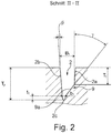
- each groove 2 is delimited by a groove flank 2a on the outside of the tread and a groove flank 2b on the inside of the tread, the groove flanks 2a, 2b to the radial direction at an angle ⁇ ( Fig. 2 ) of up to 10 °, in particular of up to 4 °.
- the groove flanks 2a, 2b can also run in the radial direction.
- each groove 2 has a width B 1 ( Fig. 2 ) from 2.0 mm to 6.0 mm.
- Fig. 3 in combination with Fig. 1 shows, wedge-shaped projections 9 are formed in each tread half in the two further tread grooves 2 on the groove flanks 2a, 2b, which are evenly distributed within the groove 2 at regular intervals over the entire groove extension.
- Two projections 9 are formed on the tread flanks 2a on the inside of the tread and three projections 9 are formed on the flanks 2b on the outside of the tread.
- the projections 9 formed on the groove flank 2a are arranged alternately with the projections 9 formed on the groove flank 2b, the projections 9 lying at the groove ends directly adjoining an oblique groove 1.
- the projections 9 project in plan view from the level of the groove flanks 2a, 2b into the groove 2 such that the two projections 9 formed on the groove flank 2a each protrude into the space between the projections 9 formed on the opposite groove flank 2b.
- a groove-like groove base path 2c thus remains between the projections 9 formed on the mutually opposite groove flanks 2a, 2b.
- Each projection 9 is delimited in the radial direction by an inclined surface 9a, which, like Fig. 2 shows, viewed in cross section of the groove 2, to the radial direction at an angle ⁇ of 10 ° to 70 °, in particular from 30 ° to 45 °, and is inclined such that it starts from a depth T 1 determined in the radial direction of the respective groove flank 2a, 2b into the groove 2 - and to the groove base path 2c - runs.
- the depth T 1 is 20% to 60%, in particular at least 40%, of the profile depth Tp.
- the projections 9 are each delimited by two side surfaces 9b.
- the side surfaces 9b run at an angle of up to 10 ° to the radial direction, but can alternatively also be curved, and in particular are inclined in a plan view of the groove running direction ( Fig. 1 ).
- the three middle projections 9 essentially have the shape of an isosceles trapezium with a base lying on the groove flank 2a, 2b.
- the widest point of the projections 9 with a width of 2.5 mm to 8.0 mm, in particular of at least 5.0 mm, is located on the groove flank 2a, 2b.
- each groove base path 2c has path sections 2'c which are oriented in the running direction of the associated groove 2 and which run between a projection 9 and the respective groove flank 2a, 2b and therefore alternately along the groove flank 2a on the inside of the tread and the groove flank 2b on the outside of the tread. Between the path sections 2'c, path sections 2 "c run, which furthermore run between the projections 9 starting from opposite groove flanks 2a, 2b Fig. 2 shows, the groove base path 2c is delimited in the radial direction by a base 2 "'c, which in the exemplary embodiment shown runs at the level of the profile depth Tp.
- the base 2"' c of the groove base deposit 2c can run at a depth which is at least 90% the profile depth T P , in particular at least 95% of the profile depth T P , is.
- the groove base path 2c has a width b 1 of 0.5 mm to 1.5 mm and radial in relation to the point of the inclined surface 9a which is the lowest in cross section Direction a depth t 1 , which is at least 0.5 mm and at most 60%, in particular at most 30%, of the profile depth Tp.
- the depth t 1 of the groove base path 2c is preferably up to 2.0 mm, particularly preferably up to 1.5 mm.
- the depth t 1 of the groove base path 2c corresponding to the configuration of the projections 9, at least in the region of the path sections 2'c oriented in the running direction.
- the size of the angle ⁇ at which the inclined surfaces 9a run to the radial direction results from the profile depth Tp, the size of the depths T 1 and t 1 and the width B 1 of the groove 2.
- the invention is not limited to the exemplary embodiment described.
- at least two grooves 2 run in each tread half, at least one projection 9 being formed on each groove flank 2a, 2b of the grooves 2.
- the middle blocks 3 have a parallelogram-like shape resulting from the course of the oblique grooves 1 and grooves 2 in plan view.
- the projections 9 can be formed in all grooves 2 or only in some grooves 2.
- the shape and the number of incisions 7, 8 and their positioning within the middle blocks 3 and the shoulder-side blocks 5 may differ from the embodiment shown.
Description
Die Erfindung betrifft einen Fahrzeugluftreifen mit einem laufrichtungsgebunden ausgeführten Laufstreifen, welcher mit über die Laufstreifenbreite V-förmig zueinander verlaufenden Schrägrillen versehen ist, wobei der Laufstreifen Schulterblockreihen mit schulterseitigen Blöcken und einen zentralen Laufstreifenbereich mit mittleren Blöcken aufweist, wobei die mittleren Blöcke und die schulterseitigen Blöcke jeweils mit einer Anzahl von sich in Draufsicht parallel zueinander erstreckenden Einschnitten versehen sind, wobei im zentralen Laufstreifenbereich in jeder Laufstreifenhälfte zwischen in Umfangsrichtung benachbarten Schrägrillen zumindest zwei in Draufsicht gegensinnig zu den Schrägrillen geneigte Nuten mit Nutflanken verlaufen, welche den mittleren Blöcken gemeinsam mit den Schrägrillen in Draufsicht eine in Umfangsrichtung auf Spitzen stehende parallelogrammartige Gestalt verleihen.The invention relates to a pneumatic vehicle tire with a directional tread, which is provided with oblique grooves running across the tread width in a V-shape, the tread having rows of shoulder blocks with shoulder-side blocks and a central tread area with middle blocks, the middle blocks and the shoulder-side blocks each are provided with a number of incisions extending parallel to one another in plan view, with at least two grooves with groove flanks running in the central tread area in each tread half between obliquely adjacent grooves in the circumferential direction, which are inclined in plan view in opposite directions to the oblique grooves and which, together with the oblique grooves, show plan views in the middle blocks give a parallelogram-like shape in the circumferential direction on tips.
Ein derartiger Fahrzeugluftreifen ist beispielsweise aus der
Ein weiterer Fahrzeugluftreifen der eingangs genannten Art ist aus der
Ferner offenbart die
Darüber hinaus ist aus der
Fahrzeugluftreifen der eingangs genannten Art sind insbesondere für das Fahren unter winterlichen Fahrbedingungen geeignet. Für die Fahreigenschaften von Winterreifen ist es günstig, diese mit einem sogenannten "Softcompound"-Laufstreifen zu versehen. Unter einem "Softcompound"-Laufstreifen ist ein solcher Laufstreifen zu verstehen, dessen mit dem Untergrund in Kontakt kommender Laufstreifenbereich aus einem Gummimaterial mit einer Härte von höchstens 60 Shore A besteht. Solche "Softcompound"-Laufstreifen weisen gegenüber härteren Laufstreifen in der Bodenaufstandsfläche eine größere Breite auf, die für die Fahreigenschaften auf schnee- und/oder eisbedeckten Fahrbahnen von Vorteil ist. Die sich bei "Softcompound"-Laufstreifen unter Krafteinwirkung verbiegenden Blöcke behindern beim Fahren auf nasser Fahrbahn jedoch die Wasserdrainage, wodurch die Aquaplaninggefahr erhöht wird.Pneumatic vehicle tires of the type mentioned are particularly suitable for driving under wintry driving conditions. For the driving properties of winter tires, it is beneficial to provide them with a so-called "soft compound" tread. Under A "soft compound" tread is to be understood as a tread whose tread area that comes into contact with the ground consists of a rubber material with a hardness of at most 60 Shore A. Such "soft compound" treads have a greater width in the ground contact area than harder treads, which is advantageous for the driving properties on snow and / or ice-covered roads. The blocks which bend under the action of force in the case of "soft compound" treads, however, obstruct water drainage when driving on wet roads, which increases the risk of aquaplaning.
Der Erfindung liegt daher die Aufgabe zugrunde, einen Fahrzeugluftreifen der eingangs genannten Art derart zu gestalten, dass gute Winterfahreigenschaften, insbesondere ein optimaler Schneegriff, sichergestellt sind, wobei gleichzeitig ein hohes Wasserdrainagevermögen gewährleistet sein soll.The invention is therefore based on the object of designing a pneumatic vehicle tire of the type mentioned at the outset in such a way that good winter driving properties, in particular an optimal snow grip, are ensured, while at the same time ensuring a high water drainage capacity.
Die gestellte Aufgabe wird erfindungsgemäß dadurch gelöst, dass zu den Nuten, welche gegensinnig zu den Schrägrillen geneigte sind, Nuten gehören, an deren Nutflanken zumindest jeweils ein keilförmiger Vorsprung ausgebildet ist, welche Vorsprünge in der Erstreckungsrichtung der Nut betrachtet überlappen, wobei zwischen den von gegenüberliegenden Nutflanken ausgehenden Vorsprüngen und zwischen jedem Vorsprung und der gegenüberliegenden Nutflanke ein Nutgrundpfad mit einer Breite von 0,5 mm bis 1,5 mm verläuft, wobei der Nutgrundpfad in radialer Richtung eine Tiefe von mindestens 0,5 mm und von höchstens 60% der Profiltiefe aufweist.The object is achieved according to the invention in that the grooves, which are inclined in the opposite direction to the oblique grooves, include grooves on the groove flanks of which at least one wedge-shaped projection is formed, which projections overlap when viewed in the direction of extension of the groove, with those between opposite ones Grooved outgoing projections and between each projection and the opposite groove flank a groove base path with a width of 0.5 mm to 1.5 mm, the groove base path in the radial direction having a depth of at least 0.5 mm and a maximum of 60% of the profile depth .
Ein gemäß der Erfindung ausgeführter Laufstreifen weist somit über die Laufstreifenbreite V-förmig zueinander verlaufende Schrägrillen auf, welche als Hauptentwässerungsrillen wirken und den Laufstreifen ein hohes Wasserdrainagevermögen verleihen. Zwischen diesen Schrägrillen verlaufen Nuten, in welchen Vorsprünge positioniert sind, sodass die Nuten jeweils einen schmalen Nutgrundpfad aufweisen. Unter Belastung stützen sich die mittleren Blöcke an den Vorsprüngen und damit auch gegeneinander ab. Diese Abstützung wirkt sich insbesondere bei Softcompound-Laufstreifen stabilisierend auf die mittleren Blöcke aus, welche dadurch ein für die Traktions- und Bremseigenschaften sowie die Seitenführung auf Schneefahrbahnen optimales Biegeverhalten zeigen und zu einer deutlichen Verbesserung dieser Fahreigenschaften beitragen. Die Abstützung bzw. Stabilisierung der mittleren Blöcke trägt ferner dazu bei, dass die in den mittleren Blöcken befindlichen Einschnitte unter Krafteinwirkung länger geöffnet bleiben, sodass die Einschnitte auch in Softcompound-Reifen ihre Wirkung effektiv entfalten. Zusätzlich begünstigen die Vorsprünge sowie insbesondere der schmale Nutgrundpfad beim Fahren auf schneebedeckten Fahrbahnen die Aufnahme von Schnee in den Nuten, sodass durch "Schnee-Schnee"-Reibung zwischen dem Laufstreifen und schneebedeckten Fahrbahnen die Traktions- und die Bremseigenschaften sowie die Seitenführung auf Schnee weiter verbessert sind. Ein erfindungsgemäßer Reifen ist somit hinsichtlich seiner Fahreigenschaften unter winterlichen Fahrbedingungen und hinsichtlich seines Wasserdrainagevermögens, also seiner Aquaplaningeigenschaften, sehr gut ausbalanciert.A tread made according to the invention thus has oblique grooves running towards one another across the tread width, which act as main drainage grooves and give the tread a high water drainage capacity. Grooves, in which projections are positioned, run between these oblique grooves, so that the grooves each have a narrow groove base path. Under load, the middle blocks are supported on the projections and thus also against each other. This support has a stabilizing effect on the middle blocks, in particular in the case of soft compound treads, which thereby show an optimal bending behavior for the traction and braking properties as well as the lateral guidance on snow lanes and to one significantly improve these driving characteristics. The support or stabilization of the middle blocks also helps to keep the cuts in the middle blocks open longer under the action of force, so that the cuts also develop their effect effectively in soft compound tires. In addition, the protrusions and in particular the narrow groove base path favor the absorption of snow in the grooves when driving on snow-covered lanes, so that "snow-snow" friction between the tread and snow-covered lanes further improves traction and braking properties as well as lateral guidance on snow are. A tire according to the invention is thus very well balanced with regard to its driving properties under winter driving conditions and with regard to its water drainage capacity, that is to say its aquaplaning properties.
Gemäß einer Ausführungsvariante der Erfindung ist jeder keilförmige Vorsprung in radialer Richtung durch eine Schrägfläche begrenzt, welche, im Querschnitt der Nut betrachtet, zur radialen Richtung unter einem Winkel von 10° bis 70°, insbesondere von 30° bis 45°, verläuft und derart geneigt ist, dass die Schrägfläche ausgehend von der Nutflanke in Richtung Nutgrundpfad verläuft. Keilförmige Vorsprünge mit solchen Schrägflächen tragen beim Fahren auf schneebedeckter Fahrbahn zu einer guten Verdichtung des Schnees in den Nuten bei, wodurch die Schnee-Schnee-Reibung zwischen Laufstreifen und Fahrbahn verstärkt wird. In diesem Zusammenhang ist es zusätzlich von Vorteil, wenn die Schrägfläche von einer in radialen Richtung ermittelten Tiefe von 20% bis 60%, insbesondere von mindestens 40%, der Profiltiefe ausgehend von der Nutflanke in Richtung Nutgrundpfad verläuft.According to one embodiment variant of the invention, each wedge-shaped projection is delimited in the radial direction by an inclined surface which, viewed in cross section of the groove, extends at an angle of 10 ° to 70 °, in particular from 30 ° to 45 °, to the radial direction and is inclined in this way is that the sloping surface starts from the groove flank in the direction of the groove base path. Wedge-shaped projections with such inclined surfaces contribute to a good compression of the snow in the grooves when driving on snow-covered roads, which increases the snow-snow friction between the tread and the road. In this context, it is additionally advantageous if the inclined surface extends from a depth of 20% to 60%, in particular of at least 40%, in particular of at least 40%, of the profile depth starting from the groove flank in the direction of the groove base path.
Gemäß einer weiteren bevorzugten Ausführungsvariante ist der Nutgrundpfad durch einen Boden begrenzt, welcher auf einem Niveau von mindestens 90% der Profiltiefe, insbesondere mindestens 95% der Profiltiefe, und besonders bevorzugter Weise auf dem Niveau der Profiltiefe verläuft. Durch diese Ausgestaltung sind die nebeneinander liegenden, durch die Nuten voneinander getrennten Blöcke derart entkoppelt, dass sie, insbesondere auch durch den erwähnten Abstützungseffekt der Vorsprünge, ein besonders vorteilhaftes Kippverhalten zeigen. Ferner wird den Nuten durch derartige Nutgrundpfade ein großes Leervolumen verliehen, wodurch eine effektive Entwässerung des Laufstreifens unterstützt wird und das Wasserdrainagevermögen erhöht ist.According to a further preferred embodiment variant, the groove base path is delimited by a floor which runs at a level of at least 90% of the profile depth, in particular at least 95% of the profile depth, and particularly preferably at the level of the profile depth. By means of this configuration, the blocks lying next to one another and separated from one another by the grooves are decoupled in such a way that they exhibit a particularly advantageous tilting behavior, in particular also due to the support effect of the projections mentioned. Furthermore, the grooves through such groove base paths a large empty volume is given, which supports effective drainage of the tread and increases the water drainage capacity.
Gemäß einer weiteren bevorzugten Ausführungsvariante beträgt die Tiefe des Nutgrundpfades bis zu 2,0 mm, bevorzugt bis zu 1,5 mm. Durch die Wahl der Tiefe des Nutgrundpfades in diesen Bereichen sind Softcompound-Laufstreifen aus Gummimaterialien verschiedener Härten besonders gut hinsichtlich der beschriebenen Effekte und Fahreigenschaften optimierbar. Beispielsweise verleiht ein tieferer Nutgrundpfad gegenüber einem seichteren Nutgrundpfad der Nut ein geringeres Leervolumen bzw. eine geringere Querschnittsfläche. Eine solche Nut füllt sich beim Fahren auf Schnee besonders schnell mit Schnee, sodass der Effekt der Schnee-Schnee-Reibung verstärkt ist. Außerdem geht ein tieferer Nutgrundpfad mit einem - bezogen auf das Volumen - größeren Vorsprung einher, welcher wiederdrum den Abstützungseffekt zwischen den Blöcken verstärkt. Nuten mit seichtem Nutgrundpfad können, bedingt durch die größere Querschnittsfläche der Nut, mehr Wasser aufnehmen, sodass das Wasserdrainagevermögen erhöht ist.According to a further preferred embodiment variant, the depth of the groove base path is up to 2.0 mm, preferably up to 1.5 mm. By choosing the depth of the groove base path in these areas, soft compound treads made of rubber materials of different hardness can be optimized particularly well with regard to the effects and driving properties described. For example, a deeper groove base path gives the groove a smaller empty volume or a smaller cross-sectional area than a shallower groove base path. Such a groove fills up particularly quickly with snow when driving on snow, so that the effect of snow-snow friction is reinforced. In addition, a deeper groove base path goes hand in hand with a larger projection in terms of volume, which in turn reinforces the support effect between the blocks. Grooves with a shallow groove base path can absorb more water due to the larger cross-sectional area of the groove, so that the water drainage capacity is increased.
Bevorzugter Weise weist jeder Vorsprung an der Nutflanke an seiner breitesten Stelle eine Breite von 2,5 mm bis 8,0 mm, insbesondere von mindestens 5,0 mm, auf. Insbesondere zur Erzielung ausgeprägter Abstützungseffekte ist eine Mindestbreite von 2,5 mm von Vorteil.Each projection on the groove flank preferably has a width of 2.5 mm to 8.0 mm, in particular of at least 5.0 mm, at its widest point. A minimum width of 2.5 mm is particularly advantageous for achieving pronounced support effects.
Gemäß einer weiteren bevorzugten Ausführungsvariante verlaufen im zentralen Laufstreifenbereich in jeder Laufstreifenhälfte zwischen den in Umfangsrichtung benachbarten Schrägrillen zumindest drei gegensinnig zu den Schrägrillen geneigte Nuten.According to a further preferred embodiment variant, at least three grooves inclined in opposite directions to the oblique grooves run in the tread area in each tread half between the obliquely adjacent grooves in the circumferential direction.
Es ist ferner von Vorteil, wenn in jeder Laufstreifenhälfte zumindest in den beiden weiter laufstreifenaußenseitig verlaufenden Nuten Vorsprünge ausgebildet sind. Dies ist für die Seitenführung auf Schneefahrbahnen von Vorteil.It is also advantageous if protrusions are formed in each tread half, at least in the two grooves running further outside the tread. This is advantageous for the lateral guidance on snow lanes.
Bei einer bevorzugten Ausführungsvariante ist ferner vorgesehen, dass die Anzahl der an der weiter laufstreifenaußenseitig befindlichen Nutflanke der Nuten ausgebildeten Vorsprünge größer ist als die Anzahl der an der weiter laufstreifeninnenseitig befindlichen Nutflanke ausgebildeten Vorsprünge, wobei an der weiter laufstreifenaußenseitig befindlichen Nutflanke insbesondere drei Vorsprünge und an der weiter laufstreifeninnenseitig befindlichen Nutflanke insbesondere zwei Vorsprünge ausgebildet sind. Dies bedeutet, dass vorzugsweise an den bei den einlaufenden Blockkanten der mittleren Blöcke befindlichen Nutflanken drei Vorsprünge ausgebildet sind. Diese drei Vorsprünge stützen die Blöcke vor allem unter der beim Bremsen auftretenden Kraft effektiv gegeneinander ab. Die zwei Vorsprünge an der gegenüberliegenden Nutflanke stützen die Blöcke unter Einwirkung von Traktionskraft gut ab. Diese Ausgestaltung ist insbesondere deshalb von Vorteil, da die beim Bremsen wirkende Kraft deutlich größer ist als die Traktionskraft. Die mittleren Blöcke sind bei dieser Variante somit besonders günstig gegeneinander abgestützt.In a preferred embodiment variant, it is further provided that the number of the projections formed on the groove flank of the grooves located further on the outside of the tread is greater than the number of projections formed on the groove flank located further on the inside of the tread, three projections in particular on the groove flank located further outside and on the groove flank located further inside the tread, in particular two projections are formed. This means that preferably three protrusions are formed on the groove flanks located at the incoming block edges of the middle blocks. These three projections effectively support the blocks against each other, especially under the force that occurs when braking. The two projections on the opposite flank of the groove support the blocks well under the influence of traction. This configuration is particularly advantageous because the force acting when braking is significantly greater than the traction force. In this variant, the middle blocks are supported against each other in a particularly favorable manner.
Gemäß einer weiteren bevorzugten Ausführungsvariante reicht zumindest ein an der einen Nutflanke ausgebildeter Vorsprung in den Zwischenraum zwischen zwei unmittelbar benachbarte, an der gegenüberliegenden Nutflanke ausgebildete Vorsprünge. Dadurch können sich innerhalb der Nuten unmittelbar zueinander benachbarte Vorsprünge zusätzlich gegeneinander abstützen, was insbesondere für die Quersteifigkeit des Profils und die Seitenführung von Vorteil ist.According to a further preferred embodiment variant, at least one projection formed on one groove flank extends into the intermediate space between two immediately adjacent projections formed on the opposite groove flank. As a result, projections that are directly adjacent to one another can additionally be supported against one another within the grooves, which is particularly advantageous for the transverse rigidity of the profile and the lateral guidance.
Eine besonders gleichmäßige Versteifung der mittleren Blöcke wird erreicht, wenn die innerhalb einer Nut befindlichen Vorsprünge in regelmäßigen Abständen über die Erstreckung der Nut angeordnet sind.A particularly uniform stiffening of the middle blocks is achieved if the projections located within a groove are arranged at regular intervals over the extent of the groove.
Gemäß einer weiteren bevorzugten Ausführungsvariante verlaufen die Nuten in Draufsicht zur Umfangsrichtung unter einem Winkel von 10° bis 50°, insbesondere von 25° bis 45°. Derart geneigte Nuten bilden einerseits relativ kurze Verbindungswege zwischen den Schrägrillen, wodurch vom Laufstreifen aufgenommenes Wasser besonders schnell in die Schrägrillen abgeleitet wird. Anderseits kann an diesen Nuten das durch die Schrägrillen zu den Laufstreifenaußenseiten strömende Wasser im Wesentlichen verwirbelungsfrei vorbeiströmen, was zur effektiven Wasserableitung beiträgt. In diesem Zusammenhang ist es ferner von Vorteil, wenn die Schrägrillen im zentralen Laufstreifenbereich in Draufsicht zur Umfangsrichtung unter einem Winkel von 20° bis 70°, vorzugsweise von 40° bis 60°, verlaufen.According to a further preferred embodiment variant, the grooves run in an overhead view to the circumferential direction at an angle of 10 ° to 50 °, in particular of 25 ° to 45 °. Such inclined grooves on the one hand form relatively short connecting paths between the oblique grooves, as a result of which water absorbed by the tread is drained into the oblique grooves particularly quickly. On the other hand, the water flowing through the oblique grooves to the outside of the tread can flow past these grooves essentially without swirling, which contributes to the effective drainage of water. In this context, it is also advantageous if the oblique grooves in the central tread area in plan view to the circumferential direction run at an angle of 20 ° to 70 °, preferably from 40 ° to 60 °.
Gemäß einer weiteren bevorzugten Ausführungsvariante nimmt der zentrale Laufstreifenbereich in axialer Richtung eine Breite von 50% bis 80% der Breite der Bodenaufstandsfläche ein. Gerade in diesem Laufstreifenbereich sind die beschriebenen Effekte von besonderer Bedeutung.According to a further preferred embodiment variant, the central tread area takes up a width of 50% to 80% of the width of the ground contact area in the axial direction. The effects described are particularly important in this tread area.
Bevorzugter Weise weisen die Nuten an den radial äußeren Enden ihrer Nutflanken eine Breite von 2,0 mm bis 6,0 mm auf.The grooves preferably have a width of 2.0 mm to 6.0 mm at the radially outer ends of their groove flanks.
Weitere Merkmale, Vorteile und Einzelheiten der Erfindung werden nun anhand der Zeichnung, die schematisch ein Ausführungsbeispiel der Erfindung zeigt, näher beschrieben. Dabei zeigen
-
Fig. 1 eine Draufsicht auf eine Teilabwicklung eines Laufstreifens eines Fahrzeugluftreifens mit einer Ausführungsvariante der Erfindung, -
Fig. 2 einen Schnitt entlang der Linie II-II derFig. 1 und -
Fig. 3 eine Schrägansicht einer Nut des Laufstreifens gemäß der inFig. 1 durch den Pfeil S gekennzeichneten Sichtrichtung.
-
Fig. 1 2 shows a plan view of a partial development of a tread of a pneumatic vehicle tire with an embodiment variant of the invention, -
Fig. 2 a section along the line II-II ofFig. 1 and -
Fig. 3 an oblique view of a groove of the tread according to the inFig. 1 direction of vision marked by the arrow S.
Erfindungsgemäß ausgeführte Fahrzeugluftreifen sind vorzugsweise Winterreifen in Radialbauart für Personenkraftwagen, Vans oder Light-Trucks.Pneumatic vehicle tires designed according to the invention are preferably radial-type winter tires for passenger cars, vans or light trucks.
Der in
Im zentralen Laufstreifenbereich Z verlaufen die Schrägrillen 1 in Draufsicht unter einem Winkel von 20° bis 70°, vorzugsweise von 40° bis 60°, zur Umfangsrichtung sowie beim gezeigten Ausführungsbeispiel in Draufsicht leicht gebogen. Laufstreifenaußenseitig weist jede Schrägrille 1 einen außerhalb des zentralen Laufstreifenbereiches Z verlaufenden Rillenabschnitt 1a auf, welcher in Draufsicht unter einem von der axialen Richtung um bis zu 20°, insbesondere um bis zu 12°, abweichenden Winkel verläuft.In the central tread area Z, the
In jeder Laufstreifenhälfte verlaufen im zentralen Laufstreifenbereich Z zwischen in Umfangsrichtung benachbarten Schrägrillen 1 jeweils drei Nuten 2, welche in Draufsicht unter einem Winkel α von 10° bis 50°, insbesondere von 25° bis 45°, zur Umfangsrichtung sowie bezogen auf die Umfangsrichtung gegensinnig zu den Schrägrillen 1 verlaufen. Die Nuten 2 begrenzen gemeinsam mit den Schrägrillen 1 im zentralen Laufstreifenbereich Z befindliche in Draufsicht im Wesentlichen parallelogrammförmige mittlere Blöcke 3, welche in Umfangsrichtung auf "Spitzen" stehend angeordnet sind.In each tread half, three
Zwischen in Umfangsrichtung benachbarten Rillenabschnitten 1a der Schrägrillen 1 verläuft jeweils eine Querrille 4, welche beim gezeigten Ausführungsbeispiel in eine der am weitesten laufstreifenaußenseitig verlaufenden Nuten 2 oder an den Kreuzungsbereichen der Nuten 2 mit den Schrägrillen 1 einmündet. Die Querrillen 4, die Rillenabschnitte 1a der Schrägrillen 1 und die am weitesten laufstreifenaußenseitig verlaufenden Nuten 2 begrenzen zu Schulterblockreihen 6 gehörende schulterseitige Blöcke 5. Die schulterseitigen Blöcke 5 sind in der einen Umfangsrichtung jeweils von einer Querrille 4 und in der anderen Umfangsrichtung jeweils von einem Rillenabschnitt 1a begrenzt. Laufstreifeninnenseitig sind die schulterseitigen Blöcke 5 von den laufstreifenaußenseitig verlaufenden Nuten 2 begrenzt, wobei jeder zweite schulterseitige Block 5 innerhalb jeder Schulterblockreihe 6 ferner von einem unmittelbar an den Rillenabschnitt 1a anschließenden Abschnitt einer Schrägrille 1 begrenzt ist.Between each
Jeder mittlere Block 3 und jeder schulterseitige Block 5 ist mit einer Anzahl von Einschnitten 7, 8 versehen, welche über den jeweiligen Block 3, 5 gleichmäßig verteilt sind und sich innerhalb jedes Blockes 3, 5 parallel zueinander erstrecken. Die in den mittleren Blöcken 3 verlaufenden Einschnitte 7 erstrecken sich in Draufsicht unter einem von der axialen Richtung um bis zu 35° abweichenden Winkel oder in axialer Richtung, verlaufen in Draufsicht zick-zack-förmig, alternativ insbesondere wellenförmig, und durchqueren den jeweiligen mittleren Block 3. Die schulterseitigen Blöcke 5 sind jeweils mit zwei oder drei Einschnitten 8 versehen, welche sich in Draufsicht im Wesentlichen parallel zueinander sowie im Wesentlichen parallel zum Rillenabschnitt 1a der Schrägrillen 1 erstrecken, in Draufsicht abschnittsweise trapezartig verlaufen und in eine Schrägrille 1 bzw. in eine Nut 2 einmünden. Die Einschnitte 7, 8 weisen eine Breite von 0,4 mm bis 0,8 mm und in radialer Richtung an ihrer tiefsten Stelle eine Tiefe von mindestens 50% der Profiltiefe auf. Randseitig können die Einschnitte 7, 8 in eine Schrägrille 1 bzw. eine Nut 2 einmündende, seichtere Endabschnitte aufweisen. Innerhalb der Bodenaufstandsfläche weisen die Einschnitte 7, 8 an ihren seichtesten Stellen eine Tiefe von vorzugsweise mindestens 20% der Profiltiefe auf. Die Einschnitte 8 werden zu ihren laufstreifenaußenseitigen Enden in bekannter Weise seichter.Each
Wie
Wie
Die Vorsprünge 9 ragen in Draufsicht gegenüber dem Niveau der Nutflanken 2a, 2b derart in die Nut 2 hinein, dass die beiden an der Nutflanke 2a ausgebildeten Vorsprünge 9 jeweils in den Zwischenraum zwischen die an der gegenüberliegenden Nutflanke 2b ausgebildeten Vorsprünge 9 hineinragen. Am Grund der Nut 2 verbleibt dadurch zwischen den an den einander gegenüberliegenden Nutflanken 2a, 2b ausgebildeten Vorsprüngen 9 ein rillenartiger Nutgrundpfad 2c.The
Jeder Vorsprung 9 ist in radialer Richtung durch eine Schrägfläche 9a begrenzt, welche, wie
Gemäß
Die Größe des Winkels γ, unter welchem die Schrägflächen 9a zur radialen Richtung verlaufen, ergibt sich aus der Profiltiefe Tp, der Größe der Tiefen T1 und t1 sowie der Breite B1 der Nut 2.The size of the angle γ at which the
Die Erfindung ist auf das beschriebene Ausführungsbeispiel nicht beschränkt. Insbesondere verlaufen in jeder Laufstreifenhälfte zumindest zwei Nuten 2, wobei an jeder Nutflanke 2a, 2b der Nuten 2 zumindest ein Vorsprung 9 ausgebildet ist. Die mittleren Blöcke 3 weisen in Draufsicht eine sich aus dem Verlauf der Schrägrillen 1 und Nuten 2 ergebende parallelogrammartige Form auf. Die Vorsprünge 9 können in sämtlichen Nuten 2 oder nur in einigen Nuten 2 ausgebildet sein. Die Gestalt und die Anzahl der Einschnitte 7, 8 sowie deren Positionierung innerhalb der mittleren Blöcke 3 und der schulterseitigen Blöcke 5 können von der gezeigten Ausführung abweichen.The invention is not limited to the exemplary embodiment described. In particular, at least two
- 1 ......................1 ......................
- SchrägrilleOblique groove
- 1a ....................1a ....................
- RillenabschnittGroove section
- 2 ......................2 ......................
- NutGroove
- 2a, 2b...............2a, 2b ...............
- NutflankeFlank
- 2c ....................2c ....................
- NutgrundpfadGroove base path
- 2'c, 2"c ...........2'c, 2 "c ...........
- PfadabschnittPath section
- 2"'c.................2 "'c .................
- Bodenground
- 3 ......................3 ......................
- mittlerer Blockmiddle block
- 4 ......................4 ......................
- QuerrilleCross groove
- 5 ......................5 ......................
- schulterseitige Blockshoulder block
- 6 ......................6 ......................
- SchulterblockreiheShoulder block row
- 7, 8 ..................7, 8 ..................
- Einschnittincision
- 9 ......................9 ......................
- Vorsprunghead Start
- 9a ....................9a ....................
- SchrägflächeSloping surface
- 9b ....................9b ....................
- SeitenflächeSide surface
- B, B1, BZ, b1 ....B, B 1 , B Z , b 1 ....
- Breitewidth
- P1.....................P 1 .....................
- Pfeilarrow
- T1, t1 ................T 1 , t 1 ................
- Tiefedepth
- Tp ....................T p ....................
- ProfiltiefeProfile depth
- Z......................Z ......................
- zentraler Laufstreifenbereichcentral tread area
- α, β, γ ..............α, β, γ ..............
- Winkelangle
Claims (15)
- Vehicle pneumatic tyre having a tread strip of directional configuration which is provided with oblique grooves (1) which run in a V-shaped manner with respect to one another over the tread strip width, the tread strip having shoulder block rows (6) with shoulder-side blocks (5) and a central tread strip region (Z) with central blocks (3), the central blocks (3) and the shoulder-side blocks (5) being provided in each case with a number of sipes (7, 8) which extend parallel to one another in plan view, at least two grooves (2) with groove flanks (2a, 2b), which grooves (2) are inclined in the opposite direction with respect to the oblique grooves (1) in plan view, running in the central tread strip region (Z) in each tread strip half between oblique grooves (1) which are adjacent in the circumferential direction, which grooves (2) impart a parallelogram-like design standing on its tip in the circumferential direction to the central blocks (3) together with the oblique grooves (1) in plan view, characterized in that grooves (2) belong to the grooves (2) which are inclined in the opposite direction with respect to the oblique grooves (1), on the groove flanks (2a, 2b) of which grooves (2) at least in each case one wedge-shaped projection (9) is configured, which projections (9) overlap as viewed in the direction of extent of the groove (2), a groove bottom path (2c) with a width (b1) of from 0.5 mm to 1.5 mm running between the projections (9) which emanate from opposite groove flanks (2a, 2b) and between each projection (9) and the opposite groove flank (2a, 2b), the groove bottom path (2c) having a depth (t1) in the radial direction of at least 0.5 mm and of at most 60% of the profile depth (TP).
- Vehicle pneumatic tyre according to Claim 1, characterized in that each wedge-shaped projection (9) is delimited in the radial direction by way of an oblique face (9a) which, as viewed in the cross section of the groove (2), runs at an angle (γ) with respect to the radial direction of from 10° to 70°, in particular of from 30° to 45°, and is inclined in such a way that, starting from the groove flank (2a, 2b), it runs in the direction of the groove bottom path (2c).
- Vehicle pneumatic tyre according to Claim 2, characterized in that the oblique face (9a) runs in the direction of the groove bottom path (2c), starting from the groove flank (2a, 2b), from a depth (T1) determined in the radial direction of from 20% to 60%, in particular of at least 40%, of the profile depth (TP).
- Vehicle pneumatic tyre according to one of Claims 1 to 3, characterized in that the groove bottom path (2c) is delimited by way of a bottom (2"'c) which runs at a level of at least 90% of the profile depth (TP), in particular at least 95% of the profile depth (TP), and particularly preferably at the level of the profile depth (TP).
- Pneumatic vehicle tyre according to one of Claims 1 to 4, characterized in that the depth (t1) of the groove bottom path (2c) is up to 2.0 mm, preferably up to 1.5 mm.
- Vehicle pneumatic tyre according to one of Claims 1 to 5, characterized in that each projection (9) on the groove flank (2a, 2b) has a width at its widest point of from 2.5 mm to 8.0 mm, in particular of at least 5.0 mm.
- Vehicle pneumatic tyre according to one of Claims 1 to 6, characterized in that at least three grooves (2) which are inclined in the opposite direction with respect to the oblique grooves (1) run in the central tread strip region (Z) in each tread strip half between oblique grooves (1) which are adjacent in the circumferential direction.
- Vehicle pneumatic tyre according to Claim 7, characterized in that projections (9) are configured in each tread strip half at least in the two grooves (2) which are situated further to the tread strip outer side.
- Vehicle pneumatic tyre according to one of Claims 1 to 8, characterized in that each groove (2) has a groove flank (2a) which is situated further to the tread strip outer side and a groove flank (2a) which is situated further to the tread strip inner side, the number of projections (9) which are configured on the groove flank (2a) which is situated further to the tread strip outer side being greater than the number of projections (9) which are configured on the groove flank (2a) which is situated further to the tread strip inner side, and, in particular, three projections (9) being configured on the groove flank (2a) which is situated further to the tread strip outer side and, in particular, two projections (9) being configured on the groove flank (2a) which is situated further to the tread strip inner side.
- Vehicle pneumatic tyre according to Claim 9, characterized in that at least one projection (9) which is configured on the one groove flank (2a, 2b) protrudes into the intermediate space between two immediately adjacent projections (9) which are configured on the opposite groove flank (2a, 2b).
- Vehicle pneumatic tyre according to one of Claims 1 to 10, characterized in that the projections (9) which are situated within a groove (2) are arranged at regular spacings over the extent of the groove (2).
- Vehicle pneumatic tyre according to one of Claims 1 to 11, characterized in that, in plan view, the grooves (2) run at an angle (α) with respect to the circumferential direction of from 10° to 50°, in particular of from 25° to 45°.
- Vehicle pneumatic tyre according to one of Claims 1 to 12, characterized in that, in plan view, the oblique grooves (1) in the central tread strip region (Z) run at an angle with respect to the circumferential direction of from 20° to 70°, preferably of from 40° to 60°.
- Vehicle pneumatic tyre according to one of Claims 1 to 13, characterized in that the central tread strip region (Z) assumes a width (BZ) in the axial direction of from 50% to 80% of the width (B) of the ground contact area.
- Vehicle pneumatic tyre according to one of Claims 1 to 14, characterized in that the grooves (2) have a width (B1) of from 2.0 mm to 6.0 mm at the radially outer ends of their groove flanks (2a, 2b).
Applications Claiming Priority (1)
| Application Number | Priority Date | Filing Date | Title |
|---|---|---|---|
| DE102017211130.5A DE102017211130A1 (en) | 2017-06-30 | 2017-06-30 | Vehicle tires |
Publications (2)
| Publication Number | Publication Date |
|---|---|
| EP3421264A1 EP3421264A1 (en) | 2019-01-02 |
| EP3421264B1 true EP3421264B1 (en) | 2020-06-17 |
Family
ID=61972004
Family Applications (1)
| Application Number | Title | Priority Date | Filing Date |
|---|---|---|---|
| EP18166939.1A Active EP3421264B1 (en) | 2017-06-30 | 2018-04-12 | Pneumatic tyre for a vehicle |
Country Status (2)
| Country | Link |
|---|---|
| EP (1) | EP3421264B1 (en) |
| DE (1) | DE102017211130A1 (en) |
Cited By (1)
| Publication number | Priority date | Publication date | Assignee | Title |
|---|---|---|---|---|
| WO2023274435A1 (en) * | 2021-06-29 | 2023-01-05 | Continental Reifen Deutschland Gmbh | Pneumatic vehicle tyre |
Families Citing this family (1)
| Publication number | Priority date | Publication date | Assignee | Title |
|---|---|---|---|---|
| DE102021205662A1 (en) | 2021-06-03 | 2022-12-08 | Continental Reifen Deutschland Gmbh | Vehicle Pneumatic Tires |
Family Cites Families (8)
| Publication number | Priority date | Publication date | Assignee | Title |
|---|---|---|---|---|
| US3055410A (en) * | 1960-01-29 | 1962-09-25 | Atlas Supply Company | Tires |
| AT400425B (en) * | 1993-01-28 | 1995-12-27 | Semperit Ag | VEHICLE TIRES |
| US7992607B2 (en) * | 2003-12-16 | 2011-08-09 | Bridgestone Corporation | Pneumatic tire for heavy load |
| DE102007016930A1 (en) * | 2007-04-05 | 2008-10-09 | Continental Aktiengesellschaft | Vehicle tires |
| DE102007061148A1 (en) * | 2007-12-17 | 2009-06-18 | Continental Aktiengesellschaft | Vehicle tires |
| DE102010061086A1 (en) * | 2010-12-07 | 2012-06-14 | Continental Reifen Deutschland Gmbh | Vehicle tires |
| DE102014223599A1 (en) * | 2014-11-19 | 2016-05-19 | Continental Reifen Deutschland Gmbh | Vehicle tires |
| DE102015224288A1 (en) * | 2015-12-04 | 2017-06-08 | Continental Reifen Deutschland Gmbh | Vehicle tires |
-
2017
- 2017-06-30 DE DE102017211130.5A patent/DE102017211130A1/en active Pending
-
2018
- 2018-04-12 EP EP18166939.1A patent/EP3421264B1/en active Active
Non-Patent Citations (1)
| Title |
|---|
| None * |
Cited By (1)
| Publication number | Priority date | Publication date | Assignee | Title |
|---|---|---|---|---|
| WO2023274435A1 (en) * | 2021-06-29 | 2023-01-05 | Continental Reifen Deutschland Gmbh | Pneumatic vehicle tyre |
Also Published As
| Publication number | Publication date |
|---|---|
| EP3421264A1 (en) | 2019-01-02 |
| DE102017211130A1 (en) | 2019-01-03 |
Similar Documents
| Publication | Publication Date | Title |
|---|---|---|
| DE102007061148A1 (en) | Vehicle tires | |
| EP3256334B1 (en) | Pneumatic tyre for a vehicle | |
| EP3300926B1 (en) | Pneumatic tyres for a vehicle | |
| WO2018158021A1 (en) | Pneumatic vehicle tire | |
| DE102010060946A1 (en) | Vehicle tires | |
| EP3031628A1 (en) | Pneumatic tyres for a vehicle | |
| EP3421264B1 (en) | Pneumatic tyre for a vehicle | |
| DE102008044921A1 (en) | Vehicle tires | |
| WO2017092896A1 (en) | Pneumatic vehicle tires | |
| DE202007019375U1 (en) | Vehicle tires | |
| EP2138329B1 (en) | Tire tread for pneumatic tire | |
| DE102008029659A1 (en) | Vehicle tires | |
| EP3383675B1 (en) | Pneumatic vehicle tires | |
| EP3300925B1 (en) | Pneumatic tyres for a vehicle | |
| EP3173253B1 (en) | Pneumatic tyres for a vehicle | |
| EP3256335B1 (en) | Pneumatic tyre for a vehicle | |
| EP3441241A1 (en) | Pneumatic tyres for a vehicle | |
| EP3645318B1 (en) | Pneumatic vehicle tires | |
| EP3551477B1 (en) | Vehicle tires | |
| DE102008029658A1 (en) | Vehicle tires | |
| EP2860049B1 (en) | Pneumatic tyres for a vehicle | |
| EP3079925B1 (en) | Pneumatic vehicle tire | |
| EP3715148B1 (en) | Pneumatic tyre | |
| EP3888951B1 (en) | Pneumatic tyre | |
| DE102019210431A1 (en) | Pneumatic vehicle tires |
Legal Events
| Date | Code | Title | Description |
|---|---|---|---|
| PUAI | Public reference made under article 153(3) epc to a published international application that has entered the european phase |
Free format text: ORIGINAL CODE: 0009012 |
|
| STAA | Information on the status of an ep patent application or granted ep patent |
Free format text: STATUS: THE APPLICATION HAS BEEN PUBLISHED |
|
| AK | Designated contracting states |
Kind code of ref document: A1 Designated state(s): AL AT BE BG CH CY CZ DE DK EE ES FI FR GB GR HR HU IE IS IT LI LT LU LV MC MK MT NL NO PL PT RO RS SE SI SK SM TR |
|
| AX | Request for extension of the european patent |
Extension state: BA ME |
|
| STAA | Information on the status of an ep patent application or granted ep patent |
Free format text: STATUS: REQUEST FOR EXAMINATION WAS MADE |
|
| 17P | Request for examination filed |
Effective date: 20190702 |
|
| RBV | Designated contracting states (corrected) |
Designated state(s): AL AT BE BG CH CY CZ DE DK EE ES FI FR GB GR HR HU IE IS IT LI LT LU LV MC MK MT NL NO PL PT RO RS SE SI SK SM TR |
|
| RIC1 | Information provided on ipc code assigned before grant |
Ipc: B60C 11/03 20060101ALI20200113BHEP Ipc: B60C 11/13 20060101AFI20200113BHEP Ipc: B60C 11/12 20060101ALI20200113BHEP |
|
| GRAP | Despatch of communication of intention to grant a patent |
Free format text: ORIGINAL CODE: EPIDOSNIGR1 |
|
| STAA | Information on the status of an ep patent application or granted ep patent |
Free format text: STATUS: GRANT OF PATENT IS INTENDED |
|
| INTG | Intention to grant announced |
Effective date: 20200302 |
|
| GRAS | Grant fee paid |
Free format text: ORIGINAL CODE: EPIDOSNIGR3 |
|
| GRAA | (expected) grant |
Free format text: ORIGINAL CODE: 0009210 |
|
| STAA | Information on the status of an ep patent application or granted ep patent |
Free format text: STATUS: THE PATENT HAS BEEN GRANTED |
|
| AK | Designated contracting states |
Kind code of ref document: B1 Designated state(s): AL AT BE BG CH CY CZ DE DK EE ES FI FR GB GR HR HU IE IS IT LI LT LU LV MC MK MT NL NO PL PT RO RS SE SI SK SM TR |
|
| REG | Reference to a national code |
Ref country code: GB Ref legal event code: FG4D Free format text: NOT ENGLISH |
|
| REG | Reference to a national code |
Ref country code: CH Ref legal event code: EP |
|
| REG | Reference to a national code |
Ref country code: DE Ref legal event code: R096 Ref document number: 502018001663 Country of ref document: DE |
|
| REG | Reference to a national code |
Ref country code: IE Ref legal event code: FG4D Free format text: LANGUAGE OF EP DOCUMENT: GERMAN |
|
| REG | Reference to a national code |
Ref country code: AT Ref legal event code: REF Ref document number: 1280867 Country of ref document: AT Kind code of ref document: T Effective date: 20200715 |
|
| REG | Reference to a national code |
Ref country code: SE Ref legal event code: TRGR |
|
| PG25 | Lapsed in a contracting state [announced via postgrant information from national office to epo] |
Ref country code: LT Free format text: LAPSE BECAUSE OF FAILURE TO SUBMIT A TRANSLATION OF THE DESCRIPTION OR TO PAY THE FEE WITHIN THE PRESCRIBED TIME-LIMIT Effective date: 20200617 Ref country code: GR Free format text: LAPSE BECAUSE OF FAILURE TO SUBMIT A TRANSLATION OF THE DESCRIPTION OR TO PAY THE FEE WITHIN THE PRESCRIBED TIME-LIMIT Effective date: 20200918 Ref country code: FI Free format text: LAPSE BECAUSE OF FAILURE TO SUBMIT A TRANSLATION OF THE DESCRIPTION OR TO PAY THE FEE WITHIN THE PRESCRIBED TIME-LIMIT Effective date: 20200617 |
|
| REG | Reference to a national code |
Ref country code: NO Ref legal event code: T2 Effective date: 20200617 |
|
| REG | Reference to a national code |
Ref country code: LT Ref legal event code: MG4D |
|
| REG | Reference to a national code |
Ref country code: NL Ref legal event code: MP Effective date: 20200617 |
|
| PG25 | Lapsed in a contracting state [announced via postgrant information from national office to epo] |
Ref country code: LV Free format text: LAPSE BECAUSE OF FAILURE TO SUBMIT A TRANSLATION OF THE DESCRIPTION OR TO PAY THE FEE WITHIN THE PRESCRIBED TIME-LIMIT Effective date: 20200617 Ref country code: HR Free format text: LAPSE BECAUSE OF FAILURE TO SUBMIT A TRANSLATION OF THE DESCRIPTION OR TO PAY THE FEE WITHIN THE PRESCRIBED TIME-LIMIT Effective date: 20200617 Ref country code: RS Free format text: LAPSE BECAUSE OF FAILURE TO SUBMIT A TRANSLATION OF THE DESCRIPTION OR TO PAY THE FEE WITHIN THE PRESCRIBED TIME-LIMIT Effective date: 20200617 Ref country code: BG Free format text: LAPSE BECAUSE OF FAILURE TO SUBMIT A TRANSLATION OF THE DESCRIPTION OR TO PAY THE FEE WITHIN THE PRESCRIBED TIME-LIMIT Effective date: 20200917 |
|
| RAP2 | Party data changed (patent owner data changed or rights of a patent transferred) |
Owner name: CONTINENTAL REIFEN DEUTSCHLAND GMBH |
|
| PG25 | Lapsed in a contracting state [announced via postgrant information from national office to epo] |
Ref country code: NL Free format text: LAPSE BECAUSE OF FAILURE TO SUBMIT A TRANSLATION OF THE DESCRIPTION OR TO PAY THE FEE WITHIN THE PRESCRIBED TIME-LIMIT Effective date: 20200617 Ref country code: AL Free format text: LAPSE BECAUSE OF FAILURE TO SUBMIT A TRANSLATION OF THE DESCRIPTION OR TO PAY THE FEE WITHIN THE PRESCRIBED TIME-LIMIT Effective date: 20200617 |
|
| PG25 | Lapsed in a contracting state [announced via postgrant information from national office to epo] |
Ref country code: RO Free format text: LAPSE BECAUSE OF FAILURE TO SUBMIT A TRANSLATION OF THE DESCRIPTION OR TO PAY THE FEE WITHIN THE PRESCRIBED TIME-LIMIT Effective date: 20200617 Ref country code: CZ Free format text: LAPSE BECAUSE OF FAILURE TO SUBMIT A TRANSLATION OF THE DESCRIPTION OR TO PAY THE FEE WITHIN THE PRESCRIBED TIME-LIMIT Effective date: 20200617 Ref country code: PT Free format text: LAPSE BECAUSE OF FAILURE TO SUBMIT A TRANSLATION OF THE DESCRIPTION OR TO PAY THE FEE WITHIN THE PRESCRIBED TIME-LIMIT Effective date: 20201019 Ref country code: ES Free format text: LAPSE BECAUSE OF FAILURE TO SUBMIT A TRANSLATION OF THE DESCRIPTION OR TO PAY THE FEE WITHIN THE PRESCRIBED TIME-LIMIT Effective date: 20200617 Ref country code: EE Free format text: LAPSE BECAUSE OF FAILURE TO SUBMIT A TRANSLATION OF THE DESCRIPTION OR TO PAY THE FEE WITHIN THE PRESCRIBED TIME-LIMIT Effective date: 20200617 Ref country code: IT Free format text: LAPSE BECAUSE OF FAILURE TO SUBMIT A TRANSLATION OF THE DESCRIPTION OR TO PAY THE FEE WITHIN THE PRESCRIBED TIME-LIMIT Effective date: 20200617 Ref country code: SM Free format text: LAPSE BECAUSE OF FAILURE TO SUBMIT A TRANSLATION OF THE DESCRIPTION OR TO PAY THE FEE WITHIN THE PRESCRIBED TIME-LIMIT Effective date: 20200617 |
|
| PG25 | Lapsed in a contracting state [announced via postgrant information from national office to epo] |
Ref country code: PL Free format text: LAPSE BECAUSE OF FAILURE TO SUBMIT A TRANSLATION OF THE DESCRIPTION OR TO PAY THE FEE WITHIN THE PRESCRIBED TIME-LIMIT Effective date: 20200617 Ref country code: SK Free format text: LAPSE BECAUSE OF FAILURE TO SUBMIT A TRANSLATION OF THE DESCRIPTION OR TO PAY THE FEE WITHIN THE PRESCRIBED TIME-LIMIT Effective date: 20200617 Ref country code: IS Free format text: LAPSE BECAUSE OF FAILURE TO SUBMIT A TRANSLATION OF THE DESCRIPTION OR TO PAY THE FEE WITHIN THE PRESCRIBED TIME-LIMIT Effective date: 20201017 |
|
| REG | Reference to a national code |
Ref country code: DE Ref legal event code: R097 Ref document number: 502018001663 Country of ref document: DE |
|
| PLBE | No opposition filed within time limit |
Free format text: ORIGINAL CODE: 0009261 |
|
| STAA | Information on the status of an ep patent application or granted ep patent |
Free format text: STATUS: NO OPPOSITION FILED WITHIN TIME LIMIT |
|
| PG25 | Lapsed in a contracting state [announced via postgrant information from national office to epo] |
Ref country code: DK Free format text: LAPSE BECAUSE OF FAILURE TO SUBMIT A TRANSLATION OF THE DESCRIPTION OR TO PAY THE FEE WITHIN THE PRESCRIBED TIME-LIMIT Effective date: 20200617 |
|
| 26N | No opposition filed |
Effective date: 20210318 |
|
| PG25 | Lapsed in a contracting state [announced via postgrant information from national office to epo] |
Ref country code: SI Free format text: LAPSE BECAUSE OF FAILURE TO SUBMIT A TRANSLATION OF THE DESCRIPTION OR TO PAY THE FEE WITHIN THE PRESCRIBED TIME-LIMIT Effective date: 20200617 |
|
| PG25 | Lapsed in a contracting state [announced via postgrant information from national office to epo] |
Ref country code: MC Free format text: LAPSE BECAUSE OF FAILURE TO SUBMIT A TRANSLATION OF THE DESCRIPTION OR TO PAY THE FEE WITHIN THE PRESCRIBED TIME-LIMIT Effective date: 20200617 |
|
| PG25 | Lapsed in a contracting state [announced via postgrant information from national office to epo] |
Ref country code: LU Free format text: LAPSE BECAUSE OF NON-PAYMENT OF DUE FEES Effective date: 20210412 |
|
| REG | Reference to a national code |
Ref country code: BE Ref legal event code: MM Effective date: 20210430 |
|
| PG25 | Lapsed in a contracting state [announced via postgrant information from national office to epo] |
Ref country code: FR Free format text: LAPSE BECAUSE OF NON-PAYMENT OF DUE FEES Effective date: 20210430 Ref country code: LI Free format text: LAPSE BECAUSE OF NON-PAYMENT OF DUE FEES Effective date: 20210430 Ref country code: CH Free format text: LAPSE BECAUSE OF NON-PAYMENT OF DUE FEES Effective date: 20210430 |
|
| PG25 | Lapsed in a contracting state [announced via postgrant information from national office to epo] |
Ref country code: IE Free format text: LAPSE BECAUSE OF NON-PAYMENT OF DUE FEES Effective date: 20210412 |
|
| PG25 | Lapsed in a contracting state [announced via postgrant information from national office to epo] |
Ref country code: IS Free format text: LAPSE BECAUSE OF FAILURE TO SUBMIT A TRANSLATION OF THE DESCRIPTION OR TO PAY THE FEE WITHIN THE PRESCRIBED TIME-LIMIT Effective date: 20201017 |
|
| PG25 | Lapsed in a contracting state [announced via postgrant information from national office to epo] |
Ref country code: BE Free format text: LAPSE BECAUSE OF NON-PAYMENT OF DUE FEES Effective date: 20210430 |
|
| GBPC | Gb: european patent ceased through non-payment of renewal fee |
Effective date: 20220412 |
|
| PG25 | Lapsed in a contracting state [announced via postgrant information from national office to epo] |
Ref country code: GB Free format text: LAPSE BECAUSE OF NON-PAYMENT OF DUE FEES Effective date: 20220412 |
|
| PG25 | Lapsed in a contracting state [announced via postgrant information from national office to epo] |
Ref country code: CY Free format text: LAPSE BECAUSE OF FAILURE TO SUBMIT A TRANSLATION OF THE DESCRIPTION OR TO PAY THE FEE WITHIN THE PRESCRIBED TIME-LIMIT Effective date: 20200617 |
|
| PG25 | Lapsed in a contracting state [announced via postgrant information from national office to epo] |
Ref country code: HU Free format text: LAPSE BECAUSE OF FAILURE TO SUBMIT A TRANSLATION OF THE DESCRIPTION OR TO PAY THE FEE WITHIN THE PRESCRIBED TIME-LIMIT; INVALID AB INITIO Effective date: 20180412 |
|
| PGFP | Annual fee paid to national office [announced via postgrant information from national office to epo] |
Ref country code: NO Payment date: 20230421 Year of fee payment: 6 Ref country code: DE Payment date: 20230430 Year of fee payment: 6 |
|
| PGFP | Annual fee paid to national office [announced via postgrant information from national office to epo] |
Ref country code: SE Payment date: 20230420 Year of fee payment: 6 Ref country code: AT Payment date: 20230420 Year of fee payment: 6 |
|
| REG | Reference to a national code |
Ref country code: DE Ref legal event code: R081 Ref document number: 502018001663 Country of ref document: DE Owner name: CONTINENTAL REIFEN DEUTSCHLAND GMBH, DE Free format text: FORMER OWNER: CONTINENTAL REIFEN DEUTSCHLAND GMBH, 30165 HANNOVER, DE |