EP2644275A1 - Jaw crusher - Google Patents
Jaw crusher Download PDFInfo
- Publication number
- EP2644275A1 EP2644275A1 EP20120162137 EP12162137A EP2644275A1 EP 2644275 A1 EP2644275 A1 EP 2644275A1 EP 20120162137 EP20120162137 EP 20120162137 EP 12162137 A EP12162137 A EP 12162137A EP 2644275 A1 EP2644275 A1 EP 2644275A1
- Authority
- EP
- European Patent Office
- Prior art keywords
- liner
- jaw crusher
- side liner
- width
- jaw
- Prior art date
- Legal status (The legal status is an assumption and is not a legal conclusion. Google has not performed a legal analysis and makes no representation as to the accuracy of the status listed.)
- Granted
Links
- 230000001681 protective effect Effects 0.000 claims description 5
- 241000826860 Trapezium Species 0.000 claims description 4
- 230000007423 decrease Effects 0.000 claims description 4
- 239000000463 material Substances 0.000 description 7
- 230000005484 gravity Effects 0.000 description 2
- 238000000926 separation method Methods 0.000 description 2
- 238000005299 abrasion Methods 0.000 description 1
- 239000011435 rock Substances 0.000 description 1
- 238000003466 welding Methods 0.000 description 1
Images



Classifications
-
- B—PERFORMING OPERATIONS; TRANSPORTING
- B02—CRUSHING, PULVERISING, OR DISINTEGRATING; PREPARATORY TREATMENT OF GRAIN FOR MILLING
- B02C—CRUSHING, PULVERISING, OR DISINTEGRATING IN GENERAL; MILLING GRAIN
- B02C1/00—Crushing or disintegrating by reciprocating members
- B02C1/02—Jaw crushers or pulverisers
- B02C1/04—Jaw crushers or pulverisers with single-acting jaws
-
- B—PERFORMING OPERATIONS; TRANSPORTING
- B02—CRUSHING, PULVERISING, OR DISINTEGRATING; PREPARATORY TREATMENT OF GRAIN FOR MILLING
- B02C—CRUSHING, PULVERISING, OR DISINTEGRATING IN GENERAL; MILLING GRAIN
- B02C1/00—Crushing or disintegrating by reciprocating members
- B02C1/02—Jaw crushers or pulverisers
- B02C1/10—Shape or construction of jaws
-
- B—PERFORMING OPERATIONS; TRANSPORTING
- B02—CRUSHING, PULVERISING, OR DISINTEGRATING; PREPARATORY TREATMENT OF GRAIN FOR MILLING
- B02C—CRUSHING, PULVERISING, OR DISINTEGRATING IN GENERAL; MILLING GRAIN
- B02C23/00—Auxiliary methods or auxiliary devices or accessories specially adapted for crushing or disintegrating not provided for in preceding groups or not specially adapted to apparatus covered by a single preceding group
- B02C23/04—Safety devices
Definitions
- the present invention relates to a jaw crusher and in particular, although not exclusively, to a jaw crusher having protective side liners and at least one security projection to prevent the side liners falling from their mounting position.
- Jaw crusher units typically comprise a fixed jaw and a movable jaw that define a crushing zone therebetween and a drive mechanism operative to rock the movable jaw back and forth in order to crush material in the crushing zone.
- the crushing zone defined between the fixed jaw and the movable jaw is generally convergent towards its lower discharge end so that crushable material fed to the upper and wider end of the zone is then capable of falling downward under gravity while being subject to repeated cycles of crushing movement in response to the cyclical motion of the movable jaw.
- the crushed material is then discharged under gravity through the narrower lower discharge end onto a conveyor belt for onward processing or final discharge from the crusher unit to a suitable stock pile.
- replaceable wear plates are typically fitted to the impact or crushing faces of the fixed and movable jaws. Additionally, the side walls which extend between and either side of the fixed and movable jaws and further define the crushing zone, are generally fitted with side liners.
- the wear plates and side liners a typically made from a hardened material which has maximum abrasion resistance and are designed to be replaceable.
- Example jaw crushers fitted with removable wear plates and side liners are disclosed in US 3,140,057 ; US 3,984,058 and US 2009/0152387 .
- one objective of the present invention is to provide apparatus to inhibit and in particular prevent side liners, mounted on the side walls adjacent to the fixed and movable jaws, from falling downwardly in the event that they are dislodged from their mounting position during use.
- the objective is achieved by a stop or security projection extending from the side wall at the region of the crushing zone, to one side of a respective side liner. In the event that the side liner does become dislodged, its downward movement is arrested by contact with the capture projection such that apparatus and components below the crushing zone are protected from impact damage.
- a jaw crusher comprising: a substantially fixed jaw and an apposed movable jaw, each jaw having a respective crushing face; a pair of opposed side walls extending between the fixed and movable jaws either side of each crushing face; a crushing zone defined by the fixed and movable jaws and the opposed side walls, the crushing zone having an upper region and a lower region; at least one side liner removably mounted at each of the side walls, the side liner having a length extending in a direction between the upper and lower regions of the crushing zone and a corresponding width defined by two lengthwise converging width edges wherein the width of the side liner decreases along its length; the jaw crusher characterised by: at least one capture projection extending from at least one of the side walls and positioned to one side of a respective side liner adjacent to one of the width edges, the capture projection configured to stop the side liner falling in a downward direction from the crushing zone in the event of the side liner becoming dislodged from the
- At least one of the width edges is continuously substantially straight or curved between an upper corner and a lower corner of the side liner.
- the capture projection is elongate and comprises a length and a width wherein at least a region along the length is substantially aligned with the length of the side liner. More preferably still, the capture projection is curved, bent or angled along its length. Preferably, at least a portion of the capture projection is curved, bent or angled in a direction away from the width edge of the side liner.
- the capture projection is in non-contact with the width edge of the side liner to provide a spatial gap between the capture projection and the width edge.
- at least a portion of the capture projection is in touching contact with the width edge of the side liner.
- the capture projection is welded at the side wall or is mounted at the side wall via anchorage screws, bolts or pins.
- the capture projection is removably mounted at the side walls.
- the side liner comprises substantially straight width edges extending the full length of the side liner between respective upper and lower corners, the capture projection positioned to one side of one of the straight width edges.
- a thickness by which the capture projection extends from the side wall is less than, equal to or greater than a thickness by which the side liner extends from the side wall.
- the capture projection is positioned substantially to one side of the movable jaw relative to the fixed jaw.
- the capture projection is adjustably mounted at the side wall.
- the capture projection comprises a trapezium or triangular geometry.
- the width edge adjacent the capture projection is substantially devoid of notches, recesses or indents along its length.
- the jaw crusher comprises a plurality of capture projections, each one of the plurality of capture projections positioned to one side of a width edge of a respective side liner.
- protective apparatus for a jaw crusher having side liners
- the apparatus comprising: a side liner capture device comprising a body projectable into a crushing zone of the jaw crusher from at least one side wall of the crushing zone, the side wall extending to one side and between a fixed jaw and a movable jaw; wherein the body is mountable at one side of a removable side liner mounted on the side wall adjacent one of a pair of width edges of the side liner at a region of the side liner where the width edges converge in a lengthwise direction of the side liner such that at least a portion of the body is positionable directly below at least a portion of the side liner adjacent the width edge; wherein the portion of the body is configured to abut the portion of the width edge and prevent the side liner falling in a downward direction from the crushing zone in the event of the side liner becoming dislodged from its mounted position at the side wall.
- Figure 1 is a perspective view of a jaw crusher unit 100 having a frame 108 upon which is mounted a substantially planar fixed jaw 104.
- a substantially planar movable jaw 105 is mounted eccentrically at a rotatable shaft 107 (extending from underneath an end cap 109) and is positioned separated and opposed to fixed jaw 104.
- the orientation of fixed jaw 104 and movable jaw 105 relative to one another is convergent along their respective lengths such that a separation distance between a crushing face 203 of fixed jaw 104 and a corresponding crushing face 203 of movable jaw 105 decreases in the downward lengthwise direction.
- a suitable wear plate 202 is removably attached to crushing face 203 of fixed jaw 104 and a corresponding wear plate 201 is removably attached to crushing face 203 of movable jaw 105.
- Two elongate side walls 102 are mounted at frame 108 and are aligned substantially perpendicular to a plane of fixed jaw 104. The side walls 102 extends either side of fixed jaw 104 and movable jaw 105 which collectively define a crushing zone 103.
- the opposed fixed and movable jaws 104, 105 are oriented to be inclined relative to one another and are spaced further apart at their respective upper ends than their lower ends. Accordingly, the crushing zone 103 is convergent from an upper feed region 204 to a lower discharge region 205.
- a pair of pulley wheels 101 are mounted either end of shaft 107 at an external facing side of side walls 102 being external to the crushing zone 103.
- Movable Jaw 105 is thereby configured for gyroscopic or eccentric motion with respect of fixed jaw 104 as pulley wheels 101 and shaft 107 are rotated via a suitable drive belt (not shown) attached to a drive motor (not shown). This movement of jaw 105 provides the necessary crushing action for material within zone 103 between the opposed wear plates 201 and 202. Material to be crushed is introduced into zone 103 via the open upper region 204 where it is crushed between jaws 104, 105 and subsequently discharged via the open lower region 205.
- a plurality of removably mounted side liners 106 are attached to each side wall 102 at the region of crushing zone 103.
- Side liners 106 extend the full length and width of crushing zone 103 between upper and lower regions 204, 205 and each of the opposed jaws 104,105.
- side liners 106 comprise a generally trapezium geometry having a main length extending over the crushing zone 103 between upper region 204 and lower region 205.
- Each side liner 106 also comprises a width extending perpendicular to its length and the lengthwise orientation of crushing zone 103. According to the trapezium geometry, the width of each side liner 106 decreases lengthwise from the upper 204 to lower 205 regions.
- each side liner 106 comprises two non-parallel width edges 200 that define the width of side liner 106 along its length.
- Each side liner 106 is arranged such that edges 301 converge in a downward direction from upper region 204 to lower region 205.
- the angled alignment of edges 301 is approximately parallel to the angled alignment of fixed jaw 104 and movable jaw 105.
- Each side liner 106 is mounted at each respective side wall 102 via a plurality of anchorage bolts 206 extending through side liner 106 and anchored at side wall 102.
- one side liner 106 is mounted at each side wall 102 and extends from the lower 205 to upper 204 regions of zone 103 so as to ensure that each side wall 102 is not exposed and is protected fully in use.
- each liner 106 may be divided lengthwise into two sections one above the other, where the respective side edges 301 of both the upper and lower liners 106 are substantially parallel.
- a capture projection 300 is attached to each side wall 102 and is positioned adjacent and to one side of a respective side liner 106. However, for clarity, only one capture projection 300 is illustrated.
- Each capture projection 300 is substantially elongate and comprises a first end 400 and a second end 402. According to the preferred embodiment, capture projection 300 is curved or bent along its length between ends 400, 402 such that a first length edge 403 is shorter than a second length edge 401.
- the capture projection 300 is orientated on side wall 102 such that the longest length edge 401 is positioned immediately opposed and closest to the width edge 301 of side liner 106 at the region of (to the side of) movable jaw 105.
- Capture projection 300 is attached to side wall 102 by welding.
- the projection 300 may be attached using suitable anchorages such as bolts, screws or pins similar to those used to attach the side liners 106 to side walls 102.
- Each projection 300 is positioned adjacent to the respective liner 106 so as to create a narrow spatial gap between opposed edges 401 and 301. This gap may typically be in the range of 0 to 50 mm at the closest point such that the projection 300 will always contact the liner 106 in the event of it becoming dislodged.
- Each projection 300 is curved along its length and aligned on each side wall 102 such that at least a portion (a lower region) of its length is aligned substantially parallel with the movable jaw 105 starting from end 400. The remaining (upper length) portion of projection 300 is then angled, curved or bent away from width edge 301 so as to increase the separation gap between opposed edges 301, 401 in a direction from lower region 205 to upper region 204 of crushing zone 103.
- the thickness of each projection 300 is slightly less than a thickness of each side liner 106 so as to not interfere with the motion of movable jaw 105 during operation of the crusher.
- Figure 5 illustrates the unwanted dislodgement of liner 106 from side wall 102, due to a failure of mountings 206.
- projection 300 acts to stop the liner 106 from falling from the region of zone 103 by abutment between opposed edges 301, 401.
- This abutment occurs as a region of liner 106 is positioned above a region of projection 300 in a vertical plane, parallel to the plane of each side wall 102.
- liner 106 is orientated to extend over projection 106 in the vertical plane due to the width of liner 106 being greater at its upper end than its lower end.
- a width of each projection 300 along its length is sufficient to provide the required integrity to withstand the impact and weight of liner 106 in the event of capture following its dislodgement from side wall 102.
- a length-to-width ratio of projection 300 is in the range 3 to 4:1.
- each projection 300 is positioned to one side of a respective liner 106 below its mid-length region, that is, adjacent a lower half of liner 106 closest to the discharge end 205 of zone 103.
- each projection 300 may be positioned above or at this mid length region.
- each projection 300 may be positioned at the respective side walls 102 so as to be in touching contact with a respective side liner 106 during normal operation of the crusher 100.
- a portion of the longest length edge 401 of projection 300 may contact a region along the respective width edge 301 of liner 106.
- a plurality of capture projections 300 may be positioned adjacent any single respective side liner 106 for example at an upper and a lower position along the length of liner 106. Additionally, and according to further embodiments, each capture projection 300 may be movably mounted at each respective side wall 102 so that its position relative to side liner 106 and in particular width edge 301 may be adjusted. According to further embodiments, each capture projection 300 is removably mounted at each respective side wall 102.
Landscapes
- Engineering & Computer Science (AREA)
- Food Science & Technology (AREA)
- Mechanical Engineering (AREA)
- Crushing And Grinding (AREA)
- Disintegrating Or Milling (AREA)
Abstract
Description
- The present invention relates to a jaw crusher and in particular, although not exclusively, to a jaw crusher having protective side liners and at least one security projection to prevent the side liners falling from their mounting position.
- Jaw crusher units typically comprise a fixed jaw and a movable jaw that define a crushing zone therebetween and a drive mechanism operative to rock the movable jaw back and forth in order to crush material in the crushing zone.
- The crushing zone defined between the fixed jaw and the movable jaw is generally convergent towards its lower discharge end so that crushable material fed to the upper and wider end of the zone is then capable of falling downward under gravity while being subject to repeated cycles of crushing movement in response to the cyclical motion of the movable jaw. The crushed material is then discharged under gravity through the narrower lower discharge end onto a conveyor belt for onward processing or final discharge from the crusher unit to a suitable stock pile.
- To protect the main operative components of the crusher, replaceable wear plates are typically fitted to the impact or crushing faces of the fixed and movable jaws. Additionally, the side walls which extend between and either side of the fixed and movable jaws and further define the crushing zone, are generally fitted with side liners. The wear plates and side liners a typically made from a hardened material which has maximum abrasion resistance and are designed to be replaceable.
- Example jaw crushers fitted with removable wear plates and side liners are disclosed in
US 3,140,057 ;US 3,984,058 andUS 2009/0152387 . - However, during use it is not uncommon for the protective side liners to be dislodged from their mounting position due to the continued impact with the crushed material. Once dislodged, the side liners fall downwardly into the crusher unit and damage underlying components. Inconvenient repair is then required. There is therefore a need for a jaw crusher unit that addresses these disadvantages.
- Accordingly, one objective of the present invention is to provide apparatus to inhibit and in particular prevent side liners, mounted on the side walls adjacent to the fixed and movable jaws, from falling downwardly in the event that they are dislodged from their mounting position during use. In particular, the objective is achieved by a stop or security projection extending from the side wall at the region of the crushing zone, to one side of a respective side liner. In the event that the side liner does become dislodged, its downward movement is arrested by contact with the capture projection such that apparatus and components below the crushing zone are protected from impact damage.
- According to a first aspect of the present invention that is provided a jaw crusher comprising: a substantially fixed jaw and an apposed movable jaw, each jaw having a respective crushing face; a pair of opposed side walls extending between the fixed and movable jaws either side of each crushing face; a crushing zone defined by the fixed and movable jaws and the opposed side walls, the crushing zone having an upper region and a lower region; at least one side liner removably mounted at each of the side walls, the side liner having a length extending in a direction between the upper and lower regions of the crushing zone and a corresponding width defined by two lengthwise converging width edges wherein the width of the side liner decreases along its length; the jaw crusher characterised by: at least one capture projection extending from at least one of the side walls and positioned to one side of a respective side liner adjacent to one of the width edges, the capture projection configured to stop the side liner falling in a downward direction from the crushing zone in the event of the side liner becoming dislodged from the side wall.
- Preferably, at least one of the width edges is continuously substantially straight or curved between an upper corner and a lower corner of the side liner.
- More preferably, the capture projection is elongate and comprises a length and a width wherein at least a region along the length is substantially aligned with the length of the side liner. More preferably still, the capture projection is curved, bent or angled along its length. Preferably, at least a portion of the capture projection is curved, bent or angled in a direction away from the width edge of the side liner.
- Optionally, the capture projection is in non-contact with the width edge of the side liner to provide a spatial gap between the capture projection and the width edge. Alternatively, at least a portion of the capture projection is in touching contact with the width edge of the side liner.
- Preferably, the capture projection is welded at the side wall or is mounted at the side wall via anchorage screws, bolts or pins. Optionally, the capture projection is removably mounted at the side walls.
- Optionally, the side liner comprises substantially straight width edges extending the full length of the side liner between respective upper and lower corners, the capture projection positioned to one side of one of the straight width edges. Optionally, a thickness by which the capture projection extends from the side wall is less than, equal to or greater than a thickness by which the side liner extends from the side wall.
- Preferably, the capture projection is positioned substantially to one side of the movable jaw relative to the fixed jaw. Optionally, the capture projection is adjustably mounted at the side wall. Optionally, the capture projection comprises a trapezium or triangular geometry.
- Preferably, the width edge adjacent the capture projection is substantially devoid of notches, recesses or indents along its length. Preferably, the jaw crusher comprises a plurality of capture projections, each one of the plurality of capture projections positioned to one side of a width edge of a respective side liner.
- According to a further aspect of the present invention that is provided protective apparatus for a jaw crusher having side liners, the apparatus comprising: a side liner capture device comprising a body projectable into a crushing zone of the jaw crusher from at least one side wall of the crushing zone, the side wall extending to one side and between a fixed jaw and a movable jaw; wherein the body is mountable at one side of a removable side liner mounted on the side wall adjacent one of a pair of width edges of the side liner at a region of the side liner where the width edges converge in a lengthwise direction of the side liner such that at least a portion of the body is positionable directly below at least a portion of the side liner adjacent the width edge; wherein the portion of the body is configured to abut the portion of the width edge and prevent the side liner falling in a downward direction from the crushing zone in the event of the side liner becoming dislodged from its mounted position at the side wall.
- A specific implementation of the present invention will now be described by way example only and with reference to the following drawings:
-
Figure 1 is a perspective view of a jaw crusher unit according to a specific implementation of the present invention; -
Figure 2 is further perspective view of the jaw crusher unit ofFigure 1 with selected components to one side of the crushing zone removed for image clarity; -
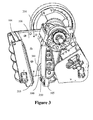
Figure 3 is a further perspective view of the jaw crusher unit ofFigure 2 showing selected components in which the side walls that, in part, define the crushing zone are protected with side liners which are, in turn, prevented from falling downward from the crushing zone by a capture projection extending from the side wall to one side of the side liner according to a specific implementation of the present invention; -
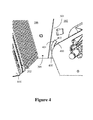
Figure 4 is a further magnified perspective view of the capture projection and jaw crusher ofFigure 3 . -
Figure 5 is further perspective view of components of the jaw crusher ofFigure 4 in which the side liner has become dislodged from its mounting position at one of the side walls and is maintained in position at the crushing zone by contact with the capture projection. -
Figure 1 is a perspective view of ajaw crusher unit 100 having aframe 108 upon which is mounted a substantially planar fixedjaw 104. A substantially planarmovable jaw 105 is mounted eccentrically at a rotatable shaft 107 (extending from underneath an end cap 109) and is positioned separated and opposed to fixedjaw 104. The orientation offixed jaw 104 andmovable jaw 105 relative to one another is convergent along their respective lengths such that a separation distance between a crushingface 203 offixed jaw 104 and a corresponding crushingface 203 ofmovable jaw 105 decreases in the downward lengthwise direction. Asuitable wear plate 202 is removably attached to crushingface 203 of fixedjaw 104 and acorresponding wear plate 201 is removably attached to crushingface 203 ofmovable jaw 105. Twoelongate side walls 102 are mounted atframe 108 and are aligned substantially perpendicular to a plane of fixedjaw 104. Theside walls 102 extends either side offixed jaw 104 andmovable jaw 105 which collectively define a crushingzone 103. - The opposed fixed and
movable jaws zone 103 is convergent from anupper feed region 204 to alower discharge region 205. - A pair of
pulley wheels 101 are mounted either end ofshaft 107 at an external facing side ofside walls 102 being external to the crushingzone 103. Movable Jaw 105 is thereby configured for gyroscopic or eccentric motion with respect of fixedjaw 104 aspulley wheels 101 andshaft 107 are rotated via a suitable drive belt (not shown) attached to a drive motor (not shown). This movement ofjaw 105 provides the necessary crushing action for material withinzone 103 between theopposed wear plates zone 103 via the openupper region 204 where it is crushed betweenjaws lower region 205. - A plurality of removably mounted
side liners 106 are attached to eachside wall 102 at the region of crushingzone 103.Side liners 106 extend the full length and width of crushingzone 103 between upper andlower regions zone 103 is convergent lengthwise,side liners 106 comprise a generally trapezium geometry having a main length extending over the crushingzone 103 betweenupper region 204 andlower region 205. Eachside liner 106 also comprises a width extending perpendicular to its length and the lengthwise orientation ofcrushing zone 103. According to the trapezium geometry, the width of eachside liner 106 decreases lengthwise from the upper 204 to lower 205 regions. - According the preferred embodiment, each
side liner 106 comprises twonon-parallel width edges 200 that define the width ofside liner 106 along its length. Eachside liner 106 is arranged such thatedges 301 converge in a downward direction fromupper region 204 tolower region 205. In particular, the angled alignment ofedges 301 is approximately parallel to the angled alignment offixed jaw 104 andmovable jaw 105. Eachside liner 106 is mounted at eachrespective side wall 102 via a plurality of anchorage bolts 206 extending throughside liner 106 and anchored atside wall 102. According to the preferred embodiment, oneside liner 106 is mounted at eachside wall 102 and extends from the lower 205 to upper 204 regions ofzone 103 so as to ensure that eachside wall 102 is not exposed and is protected fully in use. According to further embodiments eachliner 106 may be divided lengthwise into two sections one above the other, where the respective side edges 301 of both the upper andlower liners 106 are substantially parallel. - A
capture projection 300 is attached to eachside wall 102 and is positioned adjacent and to one side of arespective side liner 106. However, for clarity, only onecapture projection 300 is illustrated. Eachcapture projection 300 is substantially elongate and comprises afirst end 400 and asecond end 402. According to the preferred embodiment,capture projection 300 is curved or bent along its length between ends 400, 402 such that afirst length edge 403 is shorter than asecond length edge 401. Thecapture projection 300 is orientated onside wall 102 such that thelongest length edge 401 is positioned immediately opposed and closest to thewidth edge 301 ofside liner 106 at the region of (to the side of)movable jaw 105. -
Capture projection 300 is attached toside wall 102 by welding. Alternatively, theprojection 300 may be attached using suitable anchorages such as bolts, screws or pins similar to those used to attach theside liners 106 toside walls 102. - Each
projection 300 is positioned adjacent to therespective liner 106 so as to create a narrow spatial gap betweenopposed edges projection 300 will always contact theliner 106 in the event of it becoming dislodged. Eachprojection 300 is curved along its length and aligned on eachside wall 102 such that at least a portion (a lower region) of its length is aligned substantially parallel with themovable jaw 105 starting fromend 400. The remaining (upper length) portion ofprojection 300 is then angled, curved or bent away fromwidth edge 301 so as to increase the separation gap betweenopposed edges lower region 205 toupper region 204 of crushingzone 103. According to the preferred embodiment, the thickness of eachprojection 300 is slightly less than a thickness of eachside liner 106 so as to not interfere with the motion ofmovable jaw 105 during operation of the crusher. -
Figure 5 illustrates the unwanted dislodgement ofliner 106 fromside wall 102, due to a failure of mountings 206. In this event,projection 300 acts to stop theliner 106 from falling from the region ofzone 103 by abutment betweenopposed edges liner 106 is positioned above a region ofprojection 300 in a vertical plane, parallel to the plane of eachside wall 102. Inparticular liner 106 is orientated to extend overprojection 106 in the vertical plane due to the width ofliner 106 being greater at its upper end than its lower end. Additionally, a width of eachprojection 300 along its length is sufficient to provide the required integrity to withstand the impact and weight ofliner 106 in the event of capture following its dislodgement fromside wall 102. Approximately, a length-to-width ratio ofprojection 300 is in the range 3 to 4:1. - According to the preferred embodiment, each
projection 300 is positioned to one side of arespective liner 106 below its mid-length region, that is, adjacent a lower half ofliner 106 closest to thedischarge end 205 ofzone 103. However, according to further embodiments, eachprojection 300 may be positioned above or at this mid length region. - According to further embodiments, each
projection 300 may be positioned at therespective side walls 102 so as to be in touching contact with arespective side liner 106 during normal operation of thecrusher 100. In particular, a portion of thelongest length edge 401 ofprojection 300 may contact a region along therespective width edge 301 ofliner 106. - According to further embodiments, a plurality of
capture projections 300 may be positioned adjacent any singlerespective side liner 106 for example at an upper and a lower position along the length ofliner 106. Additionally, and according to further embodiments, eachcapture projection 300 may be movably mounted at eachrespective side wall 102 so that its position relative toside liner 106 and inparticular width edge 301 may be adjusted. According to further embodiments, eachcapture projection 300 is removably mounted at eachrespective side wall 102.
Claims (15)
- A jaw crusher (100) comprising:a substantially fixed jaw (104) and an apposed movable jaw (105);a pair of opposed side walls (102) extending either side and between the fixed (104) and movable (105) jaws;a crushing zone (103) defined by the fixed (104) and movable (105) jaws and the opposed side walls (102), the crushing zone (103) having an upper region (204) and a lower region (205);at least one side liner (106) removably mounted at each of the side walls (102), the side liner (106) having a length extending in a direction between the upper (204) and lower (205) regions of the crushing zone (103) and a corresponding width defined by two lengthwise converging width edges (301) wherein the width of the side liner (106) decreases along its length;the jaw crusher (100) characterised by:at least one capture projection (300) extending from at least one of the side walls (102) and positioned to one side of a respective side liner (106) adjacent to one of the width edges (301), the capture projection (300) configured to abut the width edge (301) and prevent the side liner (106) falling in a downward direction from the crushing zone (103) in the event of the side liner (106) becoming dislodged from the side wall (102).
- The jaw crusher (100) as claimed in claim 1 wherein at least one of the width edges (301) is continuously substantially straight or curved between an upper corner and a lower corner of the side liner (106).
- The jaw crusher (100) as claimed in claims 1 or 2 wherein the capture projection (300) is elongate and comprises a length and a width wherein at least a region along the length is substantially aligned with the length of the side liner (106).
- The jaw crusher (100) as claimed in claim 3 wherein the capture projection (300) is curved, bent or angled along its length.
- The jaw crusher (100) as claimed in any preceding claim wherein the capture projection (300) is in non-contact with the width edge (301) of the side liner (106) to provide a spatial gap between the capture projection (300) and the width edge (301).
- The jaw crusher (100) as claimed it any preceding claim wherein the capture projection (300) is welded at the side wall (102) or is mounted at the side wall (102) via anchorage screws, bolts or pins.
- The jaw crusher (100) as claimed in any preceding claim wherein the capture projection (300) is removably mounted at the side wall (102).
- The jaw crusher (100) as claimed in any preceding claim wherein the side liner (106) comprises substantially straight width edges (301) extending the full length of the side liner (106) between respective upper and lower corners, the capture projection (300) positioned to one side of one of the straight width edges (301).
- The jaw crusher (100) as claimed in claim 4 wherein at least a portion of the capture projection (300) is curved, bend or angled in a direction away from the width edge (301) of the side liner (106).
- The jaw crusher (100) as claimed in any preceding claim wherein the capture projection (300) is positioned substantially to one side of the movable jaw (105) relative to the fixed jaw (104).
- The jaw crusher (100) as claimed in any preceding claim wherein the capture projection (300) is adjustably mounted at the side wall (102).
- The jaw crusher (100) as claimed in any preceding claim wherein the side liner (106) comprises a trapezium or triangular geometry.
- The jaw crusher (100) as claimed in any preceding claim comprising a plurality of capture projections (300), each one of the plurality of capture projections (300) positioned to one side of a width edge (301) of a respective side liner (106).
- A protective capture device for a side liner (106) of a jaw crusher (100) according to anyone of the preceding claims.
- Protective apparatus for a jaw crusher (100) having side liners (106), the apparatus comprising:a side liner capture device (300) comprising a body projectable into a crushing zone (103) of the jaw crusher (100) from at least one side wall (102) of the crushing zone (103), the side wall (102) extending to one side and between a fixed jaw (104) and a movable jaw (105);wherein the body is mountable at one side of a removable side liner (106) mounted on the side wall (102) adjacent one of a pair of width edges (301) of the side liner (106) at a region of the side liner (106) where the width edges (301) converge in a lengthwise direction of the side liner (106) such that at least a portion of the body is positionable directly below at least a portion of the side liner (106) adjacent the width edge (301);wherein the portion of the body is configured to abut the portion of the width edge (301) and prevent the side liner (106) falling in a downward direction from the crushing zone (103) in the event of the side liner (106) becoming dislodged from its mounted position at the side wall (102).
Priority Applications (10)
| Application Number | Priority Date | Filing Date | Title |
|---|---|---|---|
| EP12162137.9A EP2644275B1 (en) | 2012-03-29 | 2012-03-29 | Jaw crusher |
| CN201380017433.1A CN104203413B (en) | 2012-03-29 | 2013-03-15 | Jaw Crusher |
| BR112014023944A BR112014023944A8 (en) | 2012-03-29 | 2013-03-15 | JAW CRUSHER |
| AU2013242180A AU2013242180A1 (en) | 2012-03-29 | 2013-03-15 | Jaw crusher |
| RU2014143542A RU2014143542A (en) | 2012-03-29 | 2013-03-15 | JACK CRUSHER |
| CA2866340A CA2866340A1 (en) | 2012-03-29 | 2013-03-15 | Jaw crusher |
| PCT/EP2013/055314 WO2013143871A1 (en) | 2012-03-29 | 2013-03-15 | Jaw crusher |
| US14/388,365 US20150048189A1 (en) | 2012-03-29 | 2013-03-15 | Jaw crusher |
| ZA2014/06647A ZA201406647B (en) | 2012-03-29 | 2014-09-10 | Jaw crusher |
| CL2014002546A CL2014002546A1 (en) | 2012-03-29 | 2014-09-25 | Jaw crusher comprising the fixed jaw and a juxtaposed mobile jaw, a pair of opposite side walls extending to either side and between the fixed and mobile jaws, a crushing zone defined by the fixed and mobile jaws, at least one mounted side lining of removable form in each of the side walls because at least one projection of capture extending from at least one of the side walls. |
Applications Claiming Priority (1)
| Application Number | Priority Date | Filing Date | Title |
|---|---|---|---|
| EP12162137.9A EP2644275B1 (en) | 2012-03-29 | 2012-03-29 | Jaw crusher |
Publications (2)
| Publication Number | Publication Date |
|---|---|
| EP2644275A1 true EP2644275A1 (en) | 2013-10-02 |
| EP2644275B1 EP2644275B1 (en) | 2015-10-07 |
Family
ID=47884340
Family Applications (1)
| Application Number | Title | Priority Date | Filing Date |
|---|---|---|---|
| EP12162137.9A Not-in-force EP2644275B1 (en) | 2012-03-29 | 2012-03-29 | Jaw crusher |
Country Status (10)
| Country | Link |
|---|---|
| US (1) | US20150048189A1 (en) |
| EP (1) | EP2644275B1 (en) |
| CN (1) | CN104203413B (en) |
| AU (1) | AU2013242180A1 (en) |
| BR (1) | BR112014023944A8 (en) |
| CA (1) | CA2866340A1 (en) |
| CL (1) | CL2014002546A1 (en) |
| RU (1) | RU2014143542A (en) |
| WO (1) | WO2013143871A1 (en) |
| ZA (1) | ZA201406647B (en) |
Cited By (1)
| Publication number | Priority date | Publication date | Assignee | Title |
|---|---|---|---|---|
| CN111715385A (en) * | 2020-07-02 | 2020-09-29 | 杭州大嘴兽科技有限公司 | A jaw crusher for solid waste treatment |
Families Citing this family (4)
| Publication number | Priority date | Publication date | Assignee | Title |
|---|---|---|---|---|
| CN106999939A (en) * | 2014-12-16 | 2017-08-01 | 山特维克知识产权股份有限公司 | Many driving disintegrating machines |
| USD872141S1 (en) | 2018-08-10 | 2020-01-07 | Superior Industries, Inc. | Jaw crusher forward wall |
| CN112473786A (en) * | 2020-11-13 | 2021-03-12 | 鹤岗市征楠煤化工有限公司 | High-efficient coal cinder breaker |
| US12576406B2 (en) | 2022-06-03 | 2026-03-17 | Superior Industries, Inc. | Jaw crusher systems, methods, and apparatus |
Citations (5)
| Publication number | Priority date | Publication date | Assignee | Title |
|---|---|---|---|---|
| US2701107A (en) * | 1950-05-22 | 1955-02-01 | Louis W Johnson | Rock crushing machine |
| US3140057A (en) | 1962-02-26 | 1964-07-07 | Iowa Mfg Co Cedar Rapids | Crusher jaw plates |
| US3984058A (en) | 1975-11-26 | 1976-10-05 | Barber-Greene Company | Means for holding dies in a jaw crusher |
| US6126101A (en) * | 1999-03-20 | 2000-10-03 | Cedarapids, Inc. | Double wedge key plates for a jaw crusher |
| US20090152387A1 (en) | 2005-08-29 | 2009-06-18 | Tooru Nakayama | Jaw crusher and self-traveling crusher |
Family Cites Families (13)
| Publication number | Priority date | Publication date | Assignee | Title |
|---|---|---|---|---|
| US1774159A (en) * | 1929-08-31 | 1930-08-26 | American Road Machinery Compan | Rock crusher |
| US2065784A (en) * | 1933-12-11 | 1936-12-29 | Charles J Zillgitt | Lever jaw crusher |
| US2065612A (en) * | 1935-02-01 | 1936-12-29 | Rasmussen John | Rock crusher |
| US2341105A (en) * | 1939-03-13 | 1944-02-08 | John R Kueneman | Crusher |
| US2352970A (en) * | 1942-10-16 | 1944-07-04 | Iowa Mfg Company | Crusher |
| US2453596A (en) * | 1944-06-09 | 1948-11-09 | Allis Chalmers Mfg Co | Liner plate for jaw crushers |
| DE1012146B (en) * | 1954-11-10 | 1957-07-11 | Kloeckner Humboldt Deutz Ag | Jaw crusher with eccentric drive and adjustable abutment |
| US3360206A (en) * | 1965-08-09 | 1967-12-26 | Eilers Karl Fritz | Rock crusher |
| US5323976A (en) * | 1992-09-03 | 1994-06-28 | Johnson Louis W | Lift line connection for rock crusher components |
| GB0027127D0 (en) * | 2000-11-04 | 2000-12-20 | Extec Ind Plc | Jaw crusher unit |
| JP3788427B2 (en) * | 2002-12-26 | 2006-06-21 | 河 龍干 | Jaw crusher |
| CN101342503A (en) * | 2008-08-18 | 2009-01-14 | 江苏华宏科技股份有限公司 | Novel direct drive hydraulic jaw crusher |
| CN102380435A (en) * | 2010-09-04 | 2012-03-21 | 湖北枝江峡江矿山机械有限责任公司 | Jaw crusher with V-shaped crushing cavity |
-
2012
- 2012-03-29 EP EP12162137.9A patent/EP2644275B1/en not_active Not-in-force
-
2013
- 2013-03-15 US US14/388,365 patent/US20150048189A1/en not_active Abandoned
- 2013-03-15 AU AU2013242180A patent/AU2013242180A1/en not_active Abandoned
- 2013-03-15 CA CA2866340A patent/CA2866340A1/en not_active Abandoned
- 2013-03-15 CN CN201380017433.1A patent/CN104203413B/en not_active Expired - Fee Related
- 2013-03-15 WO PCT/EP2013/055314 patent/WO2013143871A1/en not_active Ceased
- 2013-03-15 RU RU2014143542A patent/RU2014143542A/en not_active Application Discontinuation
- 2013-03-15 BR BR112014023944A patent/BR112014023944A8/en not_active IP Right Cessation
-
2014
- 2014-09-10 ZA ZA2014/06647A patent/ZA201406647B/en unknown
- 2014-09-25 CL CL2014002546A patent/CL2014002546A1/en unknown
Patent Citations (5)
| Publication number | Priority date | Publication date | Assignee | Title |
|---|---|---|---|---|
| US2701107A (en) * | 1950-05-22 | 1955-02-01 | Louis W Johnson | Rock crushing machine |
| US3140057A (en) | 1962-02-26 | 1964-07-07 | Iowa Mfg Co Cedar Rapids | Crusher jaw plates |
| US3984058A (en) | 1975-11-26 | 1976-10-05 | Barber-Greene Company | Means for holding dies in a jaw crusher |
| US6126101A (en) * | 1999-03-20 | 2000-10-03 | Cedarapids, Inc. | Double wedge key plates for a jaw crusher |
| US20090152387A1 (en) | 2005-08-29 | 2009-06-18 | Tooru Nakayama | Jaw crusher and self-traveling crusher |
Cited By (3)
| Publication number | Priority date | Publication date | Assignee | Title |
|---|---|---|---|---|
| CN111715385A (en) * | 2020-07-02 | 2020-09-29 | 杭州大嘴兽科技有限公司 | A jaw crusher for solid waste treatment |
| CN113275067A (en) * | 2020-07-02 | 2021-08-20 | 杭州大嘴兽科技有限公司 | Jaw crusher for solid waste treatment |
| CN113275068A (en) * | 2020-07-02 | 2021-08-20 | 杭州大嘴兽科技有限公司 | Jaw crusher for solid waste treatment |
Also Published As
| Publication number | Publication date |
|---|---|
| ZA201406647B (en) | 2016-10-26 |
| EP2644275B1 (en) | 2015-10-07 |
| WO2013143871A1 (en) | 2013-10-03 |
| CL2014002546A1 (en) | 2015-07-10 |
| BR112014023944A8 (en) | 2017-07-25 |
| BR112014023944A2 (en) | 2017-06-20 |
| US20150048189A1 (en) | 2015-02-19 |
| CA2866340A1 (en) | 2013-10-03 |
| RU2014143542A (en) | 2016-05-20 |
| AU2013242180A1 (en) | 2014-09-25 |
| CN104203413A (en) | 2014-12-10 |
| CN104203413B (en) | 2016-12-07 |
Similar Documents
| Publication | Publication Date | Title |
|---|---|---|
| EP2644275B1 (en) | Jaw crusher | |
| EP3248685A2 (en) | Roller crusher having at least one roller comprising a flange | |
| RU2212938C2 (en) | Jawbreaker | |
| AU2013203833C1 (en) | Roller crusher having at least one roller comprising a flange | |
| CN105813755B (en) | Locking member, locking device, jaw crusher, mineral material processing facility and the elasticity for adjusting wear parts method | |
| JP5009047B2 (en) | Impact crusher set adjustment device | |
| WO2014195066A1 (en) | Crushing jaw with plate retainer | |
| EP2669012B1 (en) | Jaw crusher support frame | |
| KR20070119212A (en) | Jaw crusher with shock absorber | |
| EP3558531B1 (en) | Jaw plate retainer | |
| KR20190107386A (en) | Safety apparatus for jaw crusher | |
| EP2990119A1 (en) | Crushing jaw with jaw plate retainer | |
| US11583864B2 (en) | Crusher assembly for a jaw crusher | |
| EP3307439B1 (en) | System and method to minimize fine material produced during crushing of frangible material | |
| US20160361720A1 (en) | System and method to minimize fine material produced during crushing of frangible material | |
| EP2653223A1 (en) | Securing device in a jaw crusher | |
| US20200016601A1 (en) | Jaw plate for a jaw crusher | |
| CN103285971A (en) | Impact flat hammer crusher |
Legal Events
| Date | Code | Title | Description |
|---|---|---|---|
| PUAI | Public reference made under article 153(3) epc to a published international application that has entered the european phase |
Free format text: ORIGINAL CODE: 0009012 |
|
| 17P | Request for examination filed |
Effective date: 20120329 |
|
| AK | Designated contracting states |
Kind code of ref document: A1 Designated state(s): AL AT BE BG CH CY CZ DE DK EE ES FI FR GB GR HR HU IE IS IT LI LT LU LV MC MK MT NL NO PL PT RO RS SE SI SK SM TR |
|
| AX | Request for extension of the european patent |
Extension state: BA ME |
|
| RBV | Designated contracting states (corrected) |
Designated state(s): AL AT BE BG CH CY CZ DE DK EE ES FI FR GB GR HR HU IE IS IT LI LT LU LV MC MK MT NL NO PL PT RO RS SE SI SK SM TR |
|
| GRAP | Despatch of communication of intention to grant a patent |
Free format text: ORIGINAL CODE: EPIDOSNIGR1 |
|
| INTG | Intention to grant announced |
Effective date: 20150522 |
|
| RIC1 | Information provided on ipc code assigned before grant |
Ipc: B02C 1/04 20060101AFI20150508BHEP Ipc: B02C 23/04 20060101ALI20150508BHEP |
|
| GRAS | Grant fee paid |
Free format text: ORIGINAL CODE: EPIDOSNIGR3 |
|
| GRAA | (expected) grant |
Free format text: ORIGINAL CODE: 0009210 |
|
| AK | Designated contracting states |
Kind code of ref document: B1 Designated state(s): AL AT BE BG CH CY CZ DE DK EE ES FI FR GB GR HR HU IE IS IT LI LT LU LV MC MK MT NL NO PL PT RO RS SE SI SK SM TR |
|
| REG | Reference to a national code |
Ref country code: GB Ref legal event code: FG4D |
|
| REG | Reference to a national code |
Ref country code: AT Ref legal event code: REF Ref document number: 753406 Country of ref document: AT Kind code of ref document: T Effective date: 20151015 Ref country code: CH Ref legal event code: EP |
|
| REG | Reference to a national code |
Ref country code: IE Ref legal event code: FG4D |
|
| REG | Reference to a national code |
Ref country code: DE Ref legal event code: R096 Ref document number: 602012011263 Country of ref document: DE |
|
| REG | Reference to a national code |
Ref country code: SE Ref legal event code: TRGR |
|
| REG | Reference to a national code |
Ref country code: NO Ref legal event code: T2 Effective date: 20151007 |
|
| REG | Reference to a national code |
Ref country code: FR Ref legal event code: PLFP Year of fee payment: 5 |
|
| REG | Reference to a national code |
Ref country code: NL Ref legal event code: MP Effective date: 20151007 |
|
| REG | Reference to a national code |
Ref country code: AT Ref legal event code: MK05 Ref document number: 753406 Country of ref document: AT Kind code of ref document: T Effective date: 20151007 |
|
| REG | Reference to a national code |
Ref country code: LT Ref legal event code: MG4D |
|
| PG25 | Lapsed in a contracting state [announced via postgrant information from national office to epo] |
Ref country code: HR Free format text: LAPSE BECAUSE OF FAILURE TO SUBMIT A TRANSLATION OF THE DESCRIPTION OR TO PAY THE FEE WITHIN THE PRESCRIBED TIME-LIMIT Effective date: 20151007 Ref country code: IT Free format text: LAPSE BECAUSE OF FAILURE TO SUBMIT A TRANSLATION OF THE DESCRIPTION OR TO PAY THE FEE WITHIN THE PRESCRIBED TIME-LIMIT Effective date: 20151007 Ref country code: LT Free format text: LAPSE BECAUSE OF FAILURE TO SUBMIT A TRANSLATION OF THE DESCRIPTION OR TO PAY THE FEE WITHIN THE PRESCRIBED TIME-LIMIT Effective date: 20151007 Ref country code: IS Free format text: LAPSE BECAUSE OF FAILURE TO SUBMIT A TRANSLATION OF THE DESCRIPTION OR TO PAY THE FEE WITHIN THE PRESCRIBED TIME-LIMIT Effective date: 20160207 Ref country code: NL Free format text: LAPSE BECAUSE OF FAILURE TO SUBMIT A TRANSLATION OF THE DESCRIPTION OR TO PAY THE FEE WITHIN THE PRESCRIBED TIME-LIMIT Effective date: 20151007 Ref country code: ES Free format text: LAPSE BECAUSE OF FAILURE TO SUBMIT A TRANSLATION OF THE DESCRIPTION OR TO PAY THE FEE WITHIN THE PRESCRIBED TIME-LIMIT Effective date: 20151007 |
|
| PGFP | Annual fee paid to national office [announced via postgrant information from national office to epo] |
Ref country code: DE Payment date: 20160322 Year of fee payment: 5 Ref country code: TR Payment date: 20160224 Year of fee payment: 5 Ref country code: NO Payment date: 20160309 Year of fee payment: 5 |
|
| PG25 | Lapsed in a contracting state [announced via postgrant information from national office to epo] |
Ref country code: PT Free format text: LAPSE BECAUSE OF FAILURE TO SUBMIT A TRANSLATION OF THE DESCRIPTION OR TO PAY THE FEE WITHIN THE PRESCRIBED TIME-LIMIT Effective date: 20160208 Ref country code: PL Free format text: LAPSE BECAUSE OF FAILURE TO SUBMIT A TRANSLATION OF THE DESCRIPTION OR TO PAY THE FEE WITHIN THE PRESCRIBED TIME-LIMIT Effective date: 20151007 Ref country code: LV Free format text: LAPSE BECAUSE OF FAILURE TO SUBMIT A TRANSLATION OF THE DESCRIPTION OR TO PAY THE FEE WITHIN THE PRESCRIBED TIME-LIMIT Effective date: 20151007 Ref country code: RS Free format text: LAPSE BECAUSE OF FAILURE TO SUBMIT A TRANSLATION OF THE DESCRIPTION OR TO PAY THE FEE WITHIN THE PRESCRIBED TIME-LIMIT Effective date: 20151007 Ref country code: AT Free format text: LAPSE BECAUSE OF FAILURE TO SUBMIT A TRANSLATION OF THE DESCRIPTION OR TO PAY THE FEE WITHIN THE PRESCRIBED TIME-LIMIT Effective date: 20151007 Ref country code: GR Free format text: LAPSE BECAUSE OF FAILURE TO SUBMIT A TRANSLATION OF THE DESCRIPTION OR TO PAY THE FEE WITHIN THE PRESCRIBED TIME-LIMIT Effective date: 20160108 |
|
| PGFP | Annual fee paid to national office [announced via postgrant information from national office to epo] |
Ref country code: SE Payment date: 20160311 Year of fee payment: 5 Ref country code: FR Payment date: 20160208 Year of fee payment: 5 Ref country code: FI Payment date: 20160309 Year of fee payment: 5 Ref country code: GB Payment date: 20160323 Year of fee payment: 5 |
|
| REG | Reference to a national code |
Ref country code: DE Ref legal event code: R097 Ref document number: 602012011263 Country of ref document: DE |
|
| PG25 | Lapsed in a contracting state [announced via postgrant information from national office to epo] |
Ref country code: CZ Free format text: LAPSE BECAUSE OF FAILURE TO SUBMIT A TRANSLATION OF THE DESCRIPTION OR TO PAY THE FEE WITHIN THE PRESCRIBED TIME-LIMIT Effective date: 20151007 |
|
| PLBE | No opposition filed within time limit |
Free format text: ORIGINAL CODE: 0009261 |
|
| STAA | Information on the status of an ep patent application or granted ep patent |
Free format text: STATUS: NO OPPOSITION FILED WITHIN TIME LIMIT |
|
| PG25 | Lapsed in a contracting state [announced via postgrant information from national office to epo] |
Ref country code: SK Free format text: LAPSE BECAUSE OF FAILURE TO SUBMIT A TRANSLATION OF THE DESCRIPTION OR TO PAY THE FEE WITHIN THE PRESCRIBED TIME-LIMIT Effective date: 20151007 Ref country code: RO Free format text: LAPSE BECAUSE OF FAILURE TO SUBMIT A TRANSLATION OF THE DESCRIPTION OR TO PAY THE FEE WITHIN THE PRESCRIBED TIME-LIMIT Effective date: 20151007 Ref country code: EE Free format text: LAPSE BECAUSE OF FAILURE TO SUBMIT A TRANSLATION OF THE DESCRIPTION OR TO PAY THE FEE WITHIN THE PRESCRIBED TIME-LIMIT Effective date: 20151007 Ref country code: BE Free format text: LAPSE BECAUSE OF NON-PAYMENT OF DUE FEES Effective date: 20160331 Ref country code: DK Free format text: LAPSE BECAUSE OF FAILURE TO SUBMIT A TRANSLATION OF THE DESCRIPTION OR TO PAY THE FEE WITHIN THE PRESCRIBED TIME-LIMIT Effective date: 20151007 Ref country code: SM Free format text: LAPSE BECAUSE OF FAILURE TO SUBMIT A TRANSLATION OF THE DESCRIPTION OR TO PAY THE FEE WITHIN THE PRESCRIBED TIME-LIMIT Effective date: 20151007 |
|
| 26N | No opposition filed |
Effective date: 20160708 |
|
| PG25 | Lapsed in a contracting state [announced via postgrant information from national office to epo] |
Ref country code: MC Free format text: LAPSE BECAUSE OF FAILURE TO SUBMIT A TRANSLATION OF THE DESCRIPTION OR TO PAY THE FEE WITHIN THE PRESCRIBED TIME-LIMIT Effective date: 20151007 Ref country code: LU Free format text: LAPSE BECAUSE OF FAILURE TO SUBMIT A TRANSLATION OF THE DESCRIPTION OR TO PAY THE FEE WITHIN THE PRESCRIBED TIME-LIMIT Effective date: 20160329 |
|
| REG | Reference to a national code |
Ref country code: CH Ref legal event code: PL |
|
| PG25 | Lapsed in a contracting state [announced via postgrant information from national office to epo] |
Ref country code: SI Free format text: LAPSE BECAUSE OF FAILURE TO SUBMIT A TRANSLATION OF THE DESCRIPTION OR TO PAY THE FEE WITHIN THE PRESCRIBED TIME-LIMIT Effective date: 20151007 |
|
| REG | Reference to a national code |
Ref country code: IE Ref legal event code: MM4A |
|
| PG25 | Lapsed in a contracting state [announced via postgrant information from national office to epo] |
Ref country code: BE Free format text: LAPSE BECAUSE OF FAILURE TO SUBMIT A TRANSLATION OF THE DESCRIPTION OR TO PAY THE FEE WITHIN THE PRESCRIBED TIME-LIMIT Effective date: 20151007 |
|
| PG25 | Lapsed in a contracting state [announced via postgrant information from national office to epo] |
Ref country code: IE Free format text: LAPSE BECAUSE OF NON-PAYMENT OF DUE FEES Effective date: 20160329 Ref country code: LI Free format text: LAPSE BECAUSE OF NON-PAYMENT OF DUE FEES Effective date: 20160331 Ref country code: CH Free format text: LAPSE BECAUSE OF NON-PAYMENT OF DUE FEES Effective date: 20160331 |
|
| PG25 | Lapsed in a contracting state [announced via postgrant information from national office to epo] |
Ref country code: MT Free format text: LAPSE BECAUSE OF FAILURE TO SUBMIT A TRANSLATION OF THE DESCRIPTION OR TO PAY THE FEE WITHIN THE PRESCRIBED TIME-LIMIT Effective date: 20151007 |
|
| REG | Reference to a national code |
Ref country code: DE Ref legal event code: R119 Ref document number: 602012011263 Country of ref document: DE |
|
| REG | Reference to a national code |
Ref country code: NO Ref legal event code: MMEP |
|
| PG25 | Lapsed in a contracting state [announced via postgrant information from national office to epo] |
Ref country code: FI Free format text: LAPSE BECAUSE OF NON-PAYMENT OF DUE FEES Effective date: 20170329 |
|
| REG | Reference to a national code |
Ref country code: SE Ref legal event code: EUG |
|
| GBPC | Gb: european patent ceased through non-payment of renewal fee |
Effective date: 20170329 |
|
| PG25 | Lapsed in a contracting state [announced via postgrant information from national office to epo] |
Ref country code: SE Free format text: LAPSE BECAUSE OF NON-PAYMENT OF DUE FEES Effective date: 20170330 |
|
| REG | Reference to a national code |
Ref country code: FR Ref legal event code: ST Effective date: 20171130 |
|
| PG25 | Lapsed in a contracting state [announced via postgrant information from national office to epo] |
Ref country code: NO Free format text: LAPSE BECAUSE OF NON-PAYMENT OF DUE FEES Effective date: 20170331 Ref country code: DE Free format text: LAPSE BECAUSE OF NON-PAYMENT OF DUE FEES Effective date: 20171003 Ref country code: FR Free format text: LAPSE BECAUSE OF NON-PAYMENT OF DUE FEES Effective date: 20170331 |
|
| PG25 | Lapsed in a contracting state [announced via postgrant information from national office to epo] |
Ref country code: GB Free format text: LAPSE BECAUSE OF NON-PAYMENT OF DUE FEES Effective date: 20170329 |
|
| PG25 | Lapsed in a contracting state [announced via postgrant information from national office to epo] |
Ref country code: HU Free format text: LAPSE BECAUSE OF FAILURE TO SUBMIT A TRANSLATION OF THE DESCRIPTION OR TO PAY THE FEE WITHIN THE PRESCRIBED TIME-LIMIT; INVALID AB INITIO Effective date: 20120329 Ref country code: CY Free format text: LAPSE BECAUSE OF FAILURE TO SUBMIT A TRANSLATION OF THE DESCRIPTION OR TO PAY THE FEE WITHIN THE PRESCRIBED TIME-LIMIT Effective date: 20151007 |
|
| PG25 | Lapsed in a contracting state [announced via postgrant information from national office to epo] |
Ref country code: MT Free format text: LAPSE BECAUSE OF FAILURE TO SUBMIT A TRANSLATION OF THE DESCRIPTION OR TO PAY THE FEE WITHIN THE PRESCRIBED TIME-LIMIT Effective date: 20160331 Ref country code: MK Free format text: LAPSE BECAUSE OF FAILURE TO SUBMIT A TRANSLATION OF THE DESCRIPTION OR TO PAY THE FEE WITHIN THE PRESCRIBED TIME-LIMIT Effective date: 20151007 |
|
| PG25 | Lapsed in a contracting state [announced via postgrant information from national office to epo] |
Ref country code: BG Free format text: LAPSE BECAUSE OF FAILURE TO SUBMIT A TRANSLATION OF THE DESCRIPTION OR TO PAY THE FEE WITHIN THE PRESCRIBED TIME-LIMIT Effective date: 20151007 |
|
| PG25 | Lapsed in a contracting state [announced via postgrant information from national office to epo] |
Ref country code: AL Free format text: LAPSE BECAUSE OF FAILURE TO SUBMIT A TRANSLATION OF THE DESCRIPTION OR TO PAY THE FEE WITHIN THE PRESCRIBED TIME-LIMIT Effective date: 20151007 |
|
| PG25 | Lapsed in a contracting state [announced via postgrant information from national office to epo] |
Ref country code: TR Free format text: LAPSE BECAUSE OF NON-PAYMENT OF DUE FEES Effective date: 20170329 |