EP2644246A1 - Luftfilter, der mit Mitteln zum Zusammenbau seiner Filterelemente ausgestattet ist - Google Patents
Luftfilter, der mit Mitteln zum Zusammenbau seiner Filterelemente ausgestattet ist Download PDFInfo
- Publication number
- EP2644246A1 EP2644246A1 EP13161247.5A EP13161247A EP2644246A1 EP 2644246 A1 EP2644246 A1 EP 2644246A1 EP 13161247 A EP13161247 A EP 13161247A EP 2644246 A1 EP2644246 A1 EP 2644246A1
- Authority
- EP
- European Patent Office
- Prior art keywords
- filter elements
- filter
- elements
- housing
- assembly means
- Prior art date
- Legal status (The legal status is an assumption and is not a legal conclusion. Google has not performed a legal analysis and makes no representation as to the accuracy of the status listed.)
- Granted
Links
- 238000013519 translation Methods 0.000 claims abstract description 20
- 238000001914 filtration Methods 0.000 claims abstract description 12
- 239000002184 metal Substances 0.000 claims abstract description 7
- 230000005489 elastic deformation Effects 0.000 claims description 4
- 238000002347 injection Methods 0.000 claims description 4
- 239000007924 injection Substances 0.000 claims description 4
- 238000003780 insertion Methods 0.000 claims description 4
- 230000037431 insertion Effects 0.000 claims description 4
- 238000006073 displacement reaction Methods 0.000 abstract description 8
- 241000446313 Lamella Species 0.000 description 10
- 238000004873 anchoring Methods 0.000 description 5
- 230000001154 acute effect Effects 0.000 description 3
- 238000013459 approach Methods 0.000 description 2
- 230000000295 complement effect Effects 0.000 description 2
- 238000012795 verification Methods 0.000 description 2
- 230000000712 assembly Effects 0.000 description 1
- 238000000429 assembly Methods 0.000 description 1
- 239000000284 extract Substances 0.000 description 1
- 238000000605 extraction Methods 0.000 description 1
- 238000012423 maintenance Methods 0.000 description 1
- 238000012986 modification Methods 0.000 description 1
- 230000004048 modification Effects 0.000 description 1
- 238000000926 separation method Methods 0.000 description 1
- 230000035939 shock Effects 0.000 description 1
- 238000004513 sizing Methods 0.000 description 1
- 239000007787 solid Substances 0.000 description 1
- 230000005236 sound signal Effects 0.000 description 1
Images

Classifications
-
- B—PERFORMING OPERATIONS; TRANSPORTING
- B01—PHYSICAL OR CHEMICAL PROCESSES OR APPARATUS IN GENERAL
- B01D—SEPARATION
- B01D46/00—Filters or filtering processes specially modified for separating dispersed particles from gases or vapours
- B01D46/0002—Casings; Housings; Frame constructions
- B01D46/0005—Mounting of filtering elements within casings, housings or frames
-
- B—PERFORMING OPERATIONS; TRANSPORTING
- B01—PHYSICAL OR CHEMICAL PROCESSES OR APPARATUS IN GENERAL
- B01D—SEPARATION
- B01D46/00—Filters or filtering processes specially modified for separating dispersed particles from gases or vapours
- B01D46/24—Particle separators, e.g. dust precipitators, using rigid hollow filter bodies
- B01D46/2403—Particle separators, e.g. dust precipitators, using rigid hollow filter bodies characterised by the physical shape or structure of the filtering element
- B01D46/2411—Filter cartridges
-
- B—PERFORMING OPERATIONS; TRANSPORTING
- B01—PHYSICAL OR CHEMICAL PROCESSES OR APPARATUS IN GENERAL
- B01D—SEPARATION
- B01D46/00—Filters or filtering processes specially modified for separating dispersed particles from gases or vapours
- B01D46/56—Filters or filtering processes specially modified for separating dispersed particles from gases or vapours with multiple filtering elements, characterised by their mutual disposition
- B01D46/58—Filters or filtering processes specially modified for separating dispersed particles from gases or vapours with multiple filtering elements, characterised by their mutual disposition connected in parallel
- B01D46/60—Filters or filtering processes specially modified for separating dispersed particles from gases or vapours with multiple filtering elements, characterised by their mutual disposition connected in parallel arranged concentrically or coaxially
-
- B—PERFORMING OPERATIONS; TRANSPORTING
- B01—PHYSICAL OR CHEMICAL PROCESSES OR APPARATUS IN GENERAL
- B01D—SEPARATION
- B01D2265/00—Casings, housings or mounting for filters specially adapted for separating dispersed particles from gases or vapours
- B01D2265/02—Non-permanent measures for connecting different parts of the filter
- B01D2265/028—Snap, latch or clip connecting means
Definitions
- the present invention relates to the field of air filters in the field of aviation, and more specifically to the assembly means of air filters in several parts.
- Air filters in the field of aviation must meet specific congestion constraints, which makes it difficult to handle and set up the various components.
- filtering elements which are arranged in a housing because of the recoil stresses necessary for their handling; a single element could not be handled easily.
- the operator must indeed access filter elements that remain in the bottom of the housing for maintenance or replacement operations that require their extraction from the housing, which is not easy in the case of an elongated housing or in the lack of specific adapted tools.
- said assembly means comprise two means arranged facing each other on said two filtering elements arranged in the housing, said means each comprising an end attached to a filter element, and a free end having a head portion comprising an engagement surface, so that said means deform elastically during the approach of said filter elements so that the heads of said assembly means pass beyond one another, the elastic return of said means engaging their surfaces of engagement so that they cooperate and ensure the connection of the filter elements in translation in said longitudinal direction.
- Each of said head portions then comprises a positioning surface adapted to cooperate in order to guide the displacement and the elastic deformation of the sections.
- the assembly means are for example metal profiles, or made by plastic injection.
- each of the filter elements comprises at least one assembly means at each of its ends.
- Each of the filter elements then typically comprises two assembly means at each of its ends and arranged symmetrically.
- the assembly means are then typically identical.
- said filter elements have an internal cavity extending over the entire length of said filter elements, the assembly means of each of the filter elements being disposed in the internal cavity of each of the filter elements.
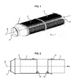
- the figure 1 shows a view of an air filter 1 comprising a housing 2 in which are housed two filter elements 3 and 4.
- the housing 2 has an elongated shape in a longitudinal direction marked on the figure 1 by a longitudinal axis Z.
- longitudinal direction means the longitudinal direction of the housing, wherein the filter elements can slide in said housing.
- a proximal end 21 of the housing 2 is defined, which is adapted to be connected to conduits of a filtration system, and a distal end 22 can be opened to extract the filter elements 3 and 4 located in the housing 2 this distal end 22 can be closed, for example by means of a lid.
- a lid advantageously closes the internal volume of the filter element 4 adjacent to the distal end 22 in a sealed manner.
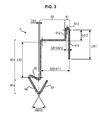
- the figure 2 schematically shows the arrangement of the filter elements 3 and 4 in the housing 2.
- the first filter element 3 which has been inserted into the housing 2 via its distal end 22 and pushed towards the proximal end 21, and the second filter element 4 which is inserted into the housing 2 via its distal end 22, the arrow in the figure showing the displacement of the second filter element 4.
- a user inserts the second filter element 4 in the housing 2, he moves it in the longitudinal direction of the housing 2 towards its proximal end 21, which will also push the first filter element 3 which had been inserted previously in the housing 2 towards this proximal end 21, until it comes to a stop.
- the distal end 22 of the housing 2 is then typically closed with a lid (not shown) as previously mentioned.
- the user opens the distal end 22 of the housing 2, then extracts the second filter element 4, and then the first filter element 3.
- the distance between the distal end 22 of the housing 2 and the filter element 3 disposed at the bottom of the housing 2 may be greater than the length of a user's arm, thus making it gripping. very complex without tools.
- the air filter as presented and comprises assembly means 5 disposed on the filter elements 3 and 4. It is identified by references 53 and 54 the assembly means respectively disposed on the first filter element 3 and the second filter element 4.
- the assembly means 5 are adapted to engage when the two filter elements 3 and 4 which are provided are arranged in the housing 2, to allow the first filter element 3 to be extracted with the second filter element 4, while can be easily disengaged by a user.
- association of the filter elements 3 and 4 in translation in the longitudinal direction Z of the housing 2, it is meant that the displacement of one of the filter elements 3 or 4 also causes a displacement of the other of the filter elements 3 or 4 , it being understood that a deflection is possible, resulting for example from a functional clearance between the assembly means.
- the figure 3 details the structure of an embodiment of assembly means 5.
- the assembly means 5 is for example formed of a metal plate having a width equal to 24 mm, a thickness equal to 0.3 mm and folded as described below.
- the support 62 is here formed of a single rectilinear segment, dimensioned so as to define a spacing E63-611 equal to 10 mm between the first segment 611 of the anchoring section 61 and the strip 63.
- This rectilinear segment is connected to the second segment 612 of the anchoring section 61 by a bend forming an angle of 90 °.
- the leaf spring 63 is formed of a single rectilinear segment, having a length L63 equal to 13.2 mm, connected to the support 62 by a bend forming an angle of 90 °.
- the engagement portion 65 of the head 64 is formed of a rectilinear segment, connected to the spring blade 63 by a bend so as to form an acute angle with said leaf spring 63, that is to say so as to the angle formed by said engagement portion 65 and said leaf spring 63 is strictly less than 90 °.
- This engagement portion 65 is then connected by a bend to the first head segment 66, which is here formed by a rectilinear segment extending towards the plane defined by said lamella 63, and connected by an elbow to the second head segment. 67 by a bend so that these two head segments 66 and 67 form an angle A66-67 equal to 60 °.
- the intersection of these two head segments 66 and 67 is for example in a plane parallel to the plane defined by the lamella 63, at a distance D63 from the lamella 63 equal to 0.5 mm.
- the assembly means 5 as shown can be made by means of shaped sheet metal, but they can also be produced by plastic injection.
- the geometry of the assembly means 5 is then adapted, in particular the head 64 which is then typically full, as well as the support 62.
- FIGS. 4 to 10 show an example of operation of such assembly means 5, during a combination and then a distance of two filter elements 3 and 4 as previously presented along the longitudinal axis Z of a housing 2 in which they are arranged .
- the figure 4 has two filter elements 3 and 4 provided with assembly means 53 and 54 respectively, these two filter elements not then being in contact.
- the figure 5 illustrates the approximation of these filter elements 3 and 4, until contact between their respective assembly means 53 and 54.
- the figure 8 illustrates the abutment of the two filter elements 3 and 4; the head of one of the filter elements has passed beyond the head of the other filter element.
- This configuration typically corresponds to the operational mode of the filter 1, that is to say that the two filter elements 3 and 4 are arranged in the housing 2 sealingly closed at its distal end 22; the assembly means 53 and 54 are then not biased along the Z axis.
- FIGS. 9 and 10 then illustrate a gradual removal of the two filter elements 3 and 4; it is noted that the heads of the two assembly means 53 and 54 cooperate to connect the filter elements 3 and 4.
- the second head segment of one of the assembly means cooperates with the engagement portion of the other assembly means for preventing the separation of the filter elements 3 and 4 during a displacement in the longitudinal direction Z.
- a user can make several movements, for example a translation in a direction perpendicular to the longitudinal direction Z.
- the user can also rotate one of the filter elements with respect to the longitudinal direction Z in order to separate the two filter elements 3 and 4.
- the user can thus fully take out the second filter element 4 from the housing 2, disengage it from the first filter element 3 for example by a translation adapted along a direction perpendicular to the longitudinal direction Z of the housing 2, and then remove the first filter element 3 from the housing 2, this first filter element then being easily accessible since near the distal end 22 of the housing 2.
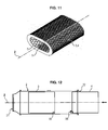
- the figure 11 illustrates an example of positioning of assembly means 5 in a filter element.
- the filter element as presented has a hollow cylinder shape along a longitudinal axis Z, its outer contour being delimited by a flange.
- the assembly means 5 are here arranged so as to project from one of the longitudinal ends of the filter element, inside the filter element.
- the filtering element comprises two symmetrically arranged connecting means 5, so that by combining two identical filter elements, the engagement takes place without require a verification of the orientation of the filter element around its Z axis, that is to say that the user does not have to check the "top” or "bottom” of the filter element.
- Symmetrical arrangement means any configuration of two assembly means 5 located symmetrically with respect to the central axis of the filter element, in this case the longitudinal axis Z.
- the assembly means 5 are aligned vertically, symmetrically with respect to the axis of the filter element, thus making it possible to ensure that by putting two identical filtering elements end to end with their assembly means 5 will be in vis-à-vis in order to cooperate. We can then also align them in a horizontal plane, symmetrically with respect to the axis of the filter element; more generally, the assembly means 5 are typically aligned symmetrically with respect to one of the main planes of the filter element in which they are arranged.
- the assembly means will advantageously be arranged in order to ensure that two identical assembly means can not be in facing relation.
- assembly means 5 at each end of each of the filter elements, so as not to require verification of the direction of insertion of these filter elements into the housing.
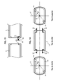
- the figure 12 illustrates an example of another embodiment of the assembly means 5.
- the assembly means 5 comprise a first assembly means 55 formed of a flange on the flange forming the structure of the filter element 3, or more generally a protruding element protruding from the inner surface of the filter element 3, and a second assembly means 56 for example similar to the assembly means presented above with reference to the Figures 2 to 11 this second assembly means 56 can be made for example by plastic injection or by means of a metal sheet.
- the flange may be specifically arranged or integrated in the geometry of the filter element, for example be formed by the inner edge of the flange forming the structure of the filter element.
- the second assembly means 56 engages the first assembly means 55 so that the two filter elements 3 and 4 are associated in their displacement in the longitudinal direction Z, and more specifically that the removal of the filter element 4 of the housing 2 also causes the removal of the filter element 3.
- the engagement of the assembly means 55 and 56 is effected via the head 64 of the assembly means 56 which passes beyond the rim forming the assembly means 55, the cooperation between the flange and the head thereby achieving the combination of the two filter elements 3 and 4.
- the rim then advantageously has a height adapted so that its end is substantially smaller than the top of the head 64 of the second assembly means 56, so that it cooperates with the second segment 67 of the head 64 as previously described so that the head 64 passes beyond the rim.
- the user moves in a direction substantially perpendicular to the longitudinal axis Z so that the two assembly means 55 and 56 are disengage, typically that the head 64 of the second assembly means 56 passes over the flange forming the first assembly means 55. The user can then remove the filter element 4 and the filter element 3 individually.
- the figure 13 presents another variant of assembly means 5 according to the embodiment illustrated in FIG. figure 12 .
- the two filter elements 3 and 4 here have a flange comprising a rim extending over the entire contour of the inner periphery of each of their ends, thus forming the first assembly means 55.
- One of the filter elements comprises a complementary assembly means 56; typically a clip or hook having a projecting head 64 and adapted to pass beyond the rim 55 and thus to engage the two filter elements 3 and 4.
- the assembly means 56 has a solid triangular section head, thus having a face forming an engaging surface 65 with the flange 55.
- the figure 14 illustrates an example of arrangement of such assembly means 5 on a filter element.
- the filter element here comprises two assembly means 56 of clip or hook type at each of its ends, symmetrically with respect to the central axis Z of the filter element, and offset by an angle ⁇ with respect to the direction vertical Y, this angle ⁇ being for example between 10 and 45 °.
- the device as described thus allows simplified handling of filter elements of an air filter disposed in an elongated housing, without requiring expensive modifications of the air filter components.
Applications Claiming Priority (1)
| Application Number | Priority Date | Filing Date | Title |
|---|---|---|---|
| FR1252794A FR2988621B1 (fr) | 2012-03-28 | 2012-03-28 | Filtre a air muni de moyens d'assemblage de ses elements filtrants |
Publications (2)
| Publication Number | Publication Date |
|---|---|
| EP2644246A1 true EP2644246A1 (de) | 2013-10-02 |
| EP2644246B1 EP2644246B1 (de) | 2018-01-17 |
Family
ID=47915127
Family Applications (1)
| Application Number | Title | Priority Date | Filing Date |
|---|---|---|---|
| EP13161247.5A Active EP2644246B1 (de) | 2012-03-28 | 2013-03-27 | Luftfilter, der mit Mitteln zum Zusammenbau seiner Filterelemente ausgestattet ist |
Country Status (2)
| Country | Link |
|---|---|
| EP (1) | EP2644246B1 (de) |
| FR (1) | FR2988621B1 (de) |
Cited By (1)
| Publication number | Priority date | Publication date | Assignee | Title |
|---|---|---|---|---|
| EP3834908A1 (de) | 2019-12-10 | 2021-06-16 | Donaldson Company, Inc. | Luftfilterelement und luftfilter damit |
Citations (5)
| Publication number | Priority date | Publication date | Assignee | Title |
|---|---|---|---|---|
| GB2265842A (en) * | 1992-04-10 | 1993-10-13 | Pall Corp | Connector for sealing stacked filter elements |
| DE19826032A1 (de) * | 1998-06-10 | 1999-12-16 | Hydac Filtertechnik Gmbh | Baukastensystem zum Aufbau von Filterelementen unterschiedlicher Baugrößen |
| EP1199093A1 (de) * | 2000-10-18 | 2002-04-24 | ARGO GmbH für Fluidtechnik | Filterelement |
| DE102004033822A1 (de) * | 2004-07-13 | 2006-02-02 | Mahle Filtersysteme Gmbh | Ringfilterelement mit axial begrenzt voneinander trennbaren Teilabschnitten |
| DE102010027150A1 (de) * | 2010-07-14 | 2012-01-19 | Mann + Hummel Gmbh | Filterelement und Filtermodul |
-
2012
- 2012-03-28 FR FR1252794A patent/FR2988621B1/fr active Active
-
2013
- 2013-03-27 EP EP13161247.5A patent/EP2644246B1/de active Active
Patent Citations (5)
| Publication number | Priority date | Publication date | Assignee | Title |
|---|---|---|---|---|
| GB2265842A (en) * | 1992-04-10 | 1993-10-13 | Pall Corp | Connector for sealing stacked filter elements |
| DE19826032A1 (de) * | 1998-06-10 | 1999-12-16 | Hydac Filtertechnik Gmbh | Baukastensystem zum Aufbau von Filterelementen unterschiedlicher Baugrößen |
| EP1199093A1 (de) * | 2000-10-18 | 2002-04-24 | ARGO GmbH für Fluidtechnik | Filterelement |
| DE102004033822A1 (de) * | 2004-07-13 | 2006-02-02 | Mahle Filtersysteme Gmbh | Ringfilterelement mit axial begrenzt voneinander trennbaren Teilabschnitten |
| DE102010027150A1 (de) * | 2010-07-14 | 2012-01-19 | Mann + Hummel Gmbh | Filterelement und Filtermodul |
Cited By (2)
| Publication number | Priority date | Publication date | Assignee | Title |
|---|---|---|---|---|
| EP3834908A1 (de) | 2019-12-10 | 2021-06-16 | Donaldson Company, Inc. | Luftfilterelement und luftfilter damit |
| WO2021119059A1 (en) | 2019-12-10 | 2021-06-17 | Donaldson Company, Inc. | Air filter element and air filter comprising same |
Also Published As
| Publication number | Publication date |
|---|---|
| EP2644246B1 (de) | 2018-01-17 |
| FR2988621B1 (fr) | 2017-05-19 |
| FR2988621A1 (fr) | 2013-10-04 |
Similar Documents
| Publication | Publication Date | Title |
|---|---|---|
| FR2889268A1 (fr) | Ensemble de fixation temporaire de deux elements, procede de montage d'une garniture interieure de portiere de vehicule et panneau de portiere realise selon ce procede de montage | |
| EP1850017B1 (de) | Selbstsperrende Verbindung zwischen einem Flachteil und einer Stange mit kugelförmigem Ende | |
| WO2015086974A1 (fr) | Element moulant comportant un moyen d'assemblage particulier | |
| EP0216669B1 (de) | Verbindungssystem für plattenförmige Elemente von halbsteifem Material und Anwendung zum Verriegeln von Kreuzfächern für Flaschenkasten in montierter Lage | |
| WO2014096634A1 (fr) | Panneaux acoustiques amovibles pour carter de turboreacteur | |
| EP1998413A1 (de) | Schutzvorrichtung für Steckelemente eines Verbinders | |
| EP2644246B1 (de) | Luftfilter, der mit Mitteln zum Zusammenbau seiner Filterelemente ausgestattet ist | |
| WO2009109729A1 (fr) | Boitier pour support multimedias et/ou support de donnees | |
| EP0496657B1 (de) | Montagevorrichtung für ein Gehäuse, insbesondere einer Heizung und/oder einer Klimaanlage, an der Karosserie eines Kraftfahrzeugs | |
| WO2006131607A1 (fr) | Dispositif de reprise d'efforts pour cables de connecteur electrique | |
| EP3016786A1 (de) | Werkzeug und verfahren zur schwächung einer kontur einer dünnen plastikkarte | |
| CH689276A5 (fr) | Classeur à levier. | |
| EP2839087B1 (de) | Ratschenverriegelungssystem | |
| EP1927495A1 (de) | Vorrichtung zur Befestigung von festen Scheiben an Passagierfahrzeugen | |
| FR2888275A1 (fr) | Dispositif de centrage d'une porte coulissante, notamment pour vehicule automobile. | |
| FR2783779A1 (fr) | Dispositif de fixation amovible d'une plaque sur un support, et procede de mise en oeuvre s'y rapportant | |
| EP2013048B1 (de) | Streifenvorrichtung mit einem haftmaterial sowie verfahren zu dessen befestigung in einem fahrzeug | |
| EP1466788A1 (de) | Sicherheitssperrvorrichtung mit Anti-Rückstosseffekt, für ein Anbauteil des Karosseriebleches eines Fahrzeuges | |
| FR3080109A1 (fr) | Dispositif decapsuleur - recapsuleur | |
| EP2814702B1 (de) | Axelfixierungssystem eines kraftfahrzeugteils | |
| EP1623933B1 (de) | Distanzstück für Glasplatten | |
| FR2913462A1 (fr) | Filtre a air muni d' agrafes de fixation | |
| EP3201480B1 (de) | Anordnung mit einem befestigungssystem zwischen einem bauteil auf einem kraftfahrzeug und fahrwerk eines kraftfahrzeugs und dem bauteil | |
| FR3021258A3 (fr) | Plot de suspension pour element de suspension d'une ligne d'echappement de vehicule automobile | |
| EP2243674B1 (de) | Servomotor und sein Montageverfahren |
Legal Events
| Date | Code | Title | Description |
|---|---|---|---|
| PUAI | Public reference made under article 153(3) epc to a published international application that has entered the european phase |
Free format text: ORIGINAL CODE: 0009012 |
|
| AK | Designated contracting states |
Kind code of ref document: A1 Designated state(s): AL AT BE BG CH CY CZ DE DK EE ES FI FR GB GR HR HU IE IS IT LI LT LU LV MC MK MT NL NO PL PT RO RS SE SI SK SM TR |
|
| AX | Request for extension of the european patent |
Extension state: BA ME |
|
| 17P | Request for examination filed |
Effective date: 20140326 |
|
| RBV | Designated contracting states (corrected) |
Designated state(s): AL AT BE BG CH CY CZ DE DK EE ES FI FR GB GR HR HU IE IS IT LI LT LU LV MC MK MT NL NO PL PT RO RS SE SI SK SM TR |
|
| 17Q | First examination report despatched |
Effective date: 20160616 |
|
| RAP1 | Party data changed (applicant data changed or rights of an application transferred) |
Owner name: SAFRAN FILTRATION SYSTEMS |
|
| GRAP | Despatch of communication of intention to grant a patent |
Free format text: ORIGINAL CODE: EPIDOSNIGR1 |
|
| INTG | Intention to grant announced |
Effective date: 20170816 |
|
| GRAS | Grant fee paid |
Free format text: ORIGINAL CODE: EPIDOSNIGR3 |
|
| GRAA | (expected) grant |
Free format text: ORIGINAL CODE: 0009210 |
|
| AK | Designated contracting states |
Kind code of ref document: B1 Designated state(s): AL AT BE BG CH CY CZ DE DK EE ES FI FR GB GR HR HU IE IS IT LI LT LU LV MC MK MT NL NO PL PT RO RS SE SI SK SM TR |
|
| REG | Reference to a national code |
Ref country code: GB Ref legal event code: FG4D Free format text: NOT ENGLISH |
|
| REG | Reference to a national code |
Ref country code: CH Ref legal event code: EP |
|
| REG | Reference to a national code |
Ref country code: IE Ref legal event code: FG4D Free format text: LANGUAGE OF EP DOCUMENT: FRENCH |
|
| REG | Reference to a national code |
Ref country code: AT Ref legal event code: REF Ref document number: 964031 Country of ref document: AT Kind code of ref document: T Effective date: 20180215 |
|
| REG | Reference to a national code |
Ref country code: DE Ref legal event code: R096 Ref document number: 602013032269 Country of ref document: DE |
|
| REG | Reference to a national code |
Ref country code: FR Ref legal event code: PLFP Year of fee payment: 6 |
|
| REG | Reference to a national code |
Ref country code: NL Ref legal event code: MP Effective date: 20180117 |
|
| REG | Reference to a national code |
Ref country code: LT Ref legal event code: MG4D |
|
| REG | Reference to a national code |
Ref country code: AT Ref legal event code: MK05 Ref document number: 964031 Country of ref document: AT Kind code of ref document: T Effective date: 20180117 |
|
| PG25 | Lapsed in a contracting state [announced via postgrant information from national office to epo] |
Ref country code: NL Free format text: LAPSE BECAUSE OF FAILURE TO SUBMIT A TRANSLATION OF THE DESCRIPTION OR TO PAY THE FEE WITHIN THE PRESCRIBED TIME-LIMIT Effective date: 20180117 |
|
| PG25 | Lapsed in a contracting state [announced via postgrant information from national office to epo] |
Ref country code: FI Free format text: LAPSE BECAUSE OF FAILURE TO SUBMIT A TRANSLATION OF THE DESCRIPTION OR TO PAY THE FEE WITHIN THE PRESCRIBED TIME-LIMIT Effective date: 20180117 Ref country code: LT Free format text: LAPSE BECAUSE OF FAILURE TO SUBMIT A TRANSLATION OF THE DESCRIPTION OR TO PAY THE FEE WITHIN THE PRESCRIBED TIME-LIMIT Effective date: 20180117 Ref country code: CY Free format text: LAPSE BECAUSE OF FAILURE TO SUBMIT A TRANSLATION OF THE DESCRIPTION OR TO PAY THE FEE WITHIN THE PRESCRIBED TIME-LIMIT Effective date: 20180117 Ref country code: ES Free format text: LAPSE BECAUSE OF FAILURE TO SUBMIT A TRANSLATION OF THE DESCRIPTION OR TO PAY THE FEE WITHIN THE PRESCRIBED TIME-LIMIT Effective date: 20180117 Ref country code: HR Free format text: LAPSE BECAUSE OF FAILURE TO SUBMIT A TRANSLATION OF THE DESCRIPTION OR TO PAY THE FEE WITHIN THE PRESCRIBED TIME-LIMIT Effective date: 20180117 Ref country code: NO Free format text: LAPSE BECAUSE OF FAILURE TO SUBMIT A TRANSLATION OF THE DESCRIPTION OR TO PAY THE FEE WITHIN THE PRESCRIBED TIME-LIMIT Effective date: 20180417 |
|
| PG25 | Lapsed in a contracting state [announced via postgrant information from national office to epo] |
Ref country code: PL Free format text: LAPSE BECAUSE OF FAILURE TO SUBMIT A TRANSLATION OF THE DESCRIPTION OR TO PAY THE FEE WITHIN THE PRESCRIBED TIME-LIMIT Effective date: 20180117 Ref country code: AT Free format text: LAPSE BECAUSE OF FAILURE TO SUBMIT A TRANSLATION OF THE DESCRIPTION OR TO PAY THE FEE WITHIN THE PRESCRIBED TIME-LIMIT Effective date: 20180117 Ref country code: RS Free format text: LAPSE BECAUSE OF FAILURE TO SUBMIT A TRANSLATION OF THE DESCRIPTION OR TO PAY THE FEE WITHIN THE PRESCRIBED TIME-LIMIT Effective date: 20180117 Ref country code: BG Free format text: LAPSE BECAUSE OF FAILURE TO SUBMIT A TRANSLATION OF THE DESCRIPTION OR TO PAY THE FEE WITHIN THE PRESCRIBED TIME-LIMIT Effective date: 20180417 Ref country code: GR Free format text: LAPSE BECAUSE OF FAILURE TO SUBMIT A TRANSLATION OF THE DESCRIPTION OR TO PAY THE FEE WITHIN THE PRESCRIBED TIME-LIMIT Effective date: 20180418 Ref country code: IS Free format text: LAPSE BECAUSE OF FAILURE TO SUBMIT A TRANSLATION OF THE DESCRIPTION OR TO PAY THE FEE WITHIN THE PRESCRIBED TIME-LIMIT Effective date: 20180517 Ref country code: SE Free format text: LAPSE BECAUSE OF FAILURE TO SUBMIT A TRANSLATION OF THE DESCRIPTION OR TO PAY THE FEE WITHIN THE PRESCRIBED TIME-LIMIT Effective date: 20180117 Ref country code: LV Free format text: LAPSE BECAUSE OF FAILURE TO SUBMIT A TRANSLATION OF THE DESCRIPTION OR TO PAY THE FEE WITHIN THE PRESCRIBED TIME-LIMIT Effective date: 20180117 |
|
| PG25 | Lapsed in a contracting state [announced via postgrant information from national office to epo] |
Ref country code: MT Free format text: LAPSE BECAUSE OF FAILURE TO SUBMIT A TRANSLATION OF THE DESCRIPTION OR TO PAY THE FEE WITHIN THE PRESCRIBED TIME-LIMIT Effective date: 20180117 |
|
| REG | Reference to a national code |
Ref country code: DE Ref legal event code: R097 Ref document number: 602013032269 Country of ref document: DE |
|
| PG25 | Lapsed in a contracting state [announced via postgrant information from national office to epo] |
Ref country code: AL Free format text: LAPSE BECAUSE OF FAILURE TO SUBMIT A TRANSLATION OF THE DESCRIPTION OR TO PAY THE FEE WITHIN THE PRESCRIBED TIME-LIMIT Effective date: 20180117 Ref country code: RO Free format text: LAPSE BECAUSE OF FAILURE TO SUBMIT A TRANSLATION OF THE DESCRIPTION OR TO PAY THE FEE WITHIN THE PRESCRIBED TIME-LIMIT Effective date: 20180117 Ref country code: EE Free format text: LAPSE BECAUSE OF FAILURE TO SUBMIT A TRANSLATION OF THE DESCRIPTION OR TO PAY THE FEE WITHIN THE PRESCRIBED TIME-LIMIT Effective date: 20180117 |
|
| REG | Reference to a national code |
Ref country code: CH Ref legal event code: PL |
|
| PLBE | No opposition filed within time limit |
Free format text: ORIGINAL CODE: 0009261 |
|
| STAA | Information on the status of an ep patent application or granted ep patent |
Free format text: STATUS: NO OPPOSITION FILED WITHIN TIME LIMIT |
|
| PG25 | Lapsed in a contracting state [announced via postgrant information from national office to epo] |
Ref country code: SK Free format text: LAPSE BECAUSE OF FAILURE TO SUBMIT A TRANSLATION OF THE DESCRIPTION OR TO PAY THE FEE WITHIN THE PRESCRIBED TIME-LIMIT Effective date: 20180117 Ref country code: SM Free format text: LAPSE BECAUSE OF FAILURE TO SUBMIT A TRANSLATION OF THE DESCRIPTION OR TO PAY THE FEE WITHIN THE PRESCRIBED TIME-LIMIT Effective date: 20180117 Ref country code: DK Free format text: LAPSE BECAUSE OF FAILURE TO SUBMIT A TRANSLATION OF THE DESCRIPTION OR TO PAY THE FEE WITHIN THE PRESCRIBED TIME-LIMIT Effective date: 20180117 Ref country code: MC Free format text: LAPSE BECAUSE OF FAILURE TO SUBMIT A TRANSLATION OF THE DESCRIPTION OR TO PAY THE FEE WITHIN THE PRESCRIBED TIME-LIMIT Effective date: 20180117 |
|
| 26N | No opposition filed |
Effective date: 20181018 |
|
| REG | Reference to a national code |
Ref country code: IE Ref legal event code: MM4A |
|
| PG25 | Lapsed in a contracting state [announced via postgrant information from national office to epo] |
Ref country code: LU Free format text: LAPSE BECAUSE OF NON-PAYMENT OF DUE FEES Effective date: 20180327 |
|
| PG25 | Lapsed in a contracting state [announced via postgrant information from national office to epo] |
Ref country code: IE Free format text: LAPSE BECAUSE OF NON-PAYMENT OF DUE FEES Effective date: 20180327 |
|
| PG25 | Lapsed in a contracting state [announced via postgrant information from national office to epo] |
Ref country code: CH Free format text: LAPSE BECAUSE OF NON-PAYMENT OF DUE FEES Effective date: 20180331 Ref country code: SI Free format text: LAPSE BECAUSE OF FAILURE TO SUBMIT A TRANSLATION OF THE DESCRIPTION OR TO PAY THE FEE WITHIN THE PRESCRIBED TIME-LIMIT Effective date: 20180117 Ref country code: LI Free format text: LAPSE BECAUSE OF NON-PAYMENT OF DUE FEES Effective date: 20180331 |
|
| PG25 | Lapsed in a contracting state [announced via postgrant information from national office to epo] |
Ref country code: TR Free format text: LAPSE BECAUSE OF FAILURE TO SUBMIT A TRANSLATION OF THE DESCRIPTION OR TO PAY THE FEE WITHIN THE PRESCRIBED TIME-LIMIT Effective date: 20180117 |
|
| PG25 | Lapsed in a contracting state [announced via postgrant information from national office to epo] |
Ref country code: PT Free format text: LAPSE BECAUSE OF FAILURE TO SUBMIT A TRANSLATION OF THE DESCRIPTION OR TO PAY THE FEE WITHIN THE PRESCRIBED TIME-LIMIT Effective date: 20180117 Ref country code: HU Free format text: LAPSE BECAUSE OF FAILURE TO SUBMIT A TRANSLATION OF THE DESCRIPTION OR TO PAY THE FEE WITHIN THE PRESCRIBED TIME-LIMIT; INVALID AB INITIO Effective date: 20130327 |
|
| PG25 | Lapsed in a contracting state [announced via postgrant information from national office to epo] |
Ref country code: MK Free format text: LAPSE BECAUSE OF NON-PAYMENT OF DUE FEES Effective date: 20180117 |
|
| PGFP | Annual fee paid to national office [announced via postgrant information from national office to epo] |
Ref country code: FR Payment date: 20230222 Year of fee payment: 11 Ref country code: CZ Payment date: 20230224 Year of fee payment: 11 |
|
| PGFP | Annual fee paid to national office [announced via postgrant information from national office to epo] |
Ref country code: IT Payment date: 20230221 Year of fee payment: 11 Ref country code: BE Payment date: 20230221 Year of fee payment: 11 |
|
| PGFP | Annual fee paid to national office [announced via postgrant information from national office to epo] |
Ref country code: DE Payment date: 20240220 Year of fee payment: 12 Ref country code: CZ Payment date: 20240226 Year of fee payment: 12 Ref country code: GB Payment date: 20240221 Year of fee payment: 12 |