EP2644089A1 - Estimation de pression sanguine à l'aide d'un dispositif à main - Google Patents
Estimation de pression sanguine à l'aide d'un dispositif à main Download PDFInfo
- Publication number
- EP2644089A1 EP2644089A1 EP13161986.8A EP13161986A EP2644089A1 EP 2644089 A1 EP2644089 A1 EP 2644089A1 EP 13161986 A EP13161986 A EP 13161986A EP 2644089 A1 EP2644089 A1 EP 2644089A1
- Authority
- EP
- European Patent Office
- Prior art keywords
- detection signals
- blood pressure
- points
- sensor
- time
- Prior art date
- Legal status (The legal status is an assumption and is not a legal conclusion. Google has not performed a legal analysis and makes no representation as to the accuracy of the status listed.)
- Granted
Links
- 230000036772 blood pressure Effects 0.000 title claims abstract description 50
- 238000001514 detection method Methods 0.000 claims abstract description 103
- 238000000034 method Methods 0.000 claims abstract description 61
- 238000000718 qrs complex Methods 0.000 claims abstract description 30
- 238000012545 processing Methods 0.000 claims abstract description 28
- 238000002565 electrocardiography Methods 0.000 claims abstract description 24
- 238000012544 monitoring process Methods 0.000 claims abstract description 24
- 230000036541 health Effects 0.000 claims abstract description 23
- 230000003287 optical effect Effects 0.000 claims abstract description 19
- 230000004044 response Effects 0.000 claims abstract description 14
- 239000008280 blood Substances 0.000 claims abstract description 9
- 210000004369 blood Anatomy 0.000 claims abstract description 9
- 238000005286 illumination Methods 0.000 claims description 34
- 238000009530 blood pressure measurement Methods 0.000 claims description 10
- 230000008569 process Effects 0.000 claims description 10
- 238000001914 filtration Methods 0.000 claims description 5
- 238000005259 measurement Methods 0.000 claims description 5
- 238000012935 Averaging Methods 0.000 claims description 2
- 238000012417 linear regression Methods 0.000 claims description 2
- 230000006870 function Effects 0.000 description 17
- 238000007626 photothermal therapy Methods 0.000 description 11
- 210000003811 finger Anatomy 0.000 description 10
- 238000013507 mapping Methods 0.000 description 10
- 229920002215 polytrimethylene terephthalate Polymers 0.000 description 10
- 238000004590 computer program Methods 0.000 description 7
- 230000015654 memory Effects 0.000 description 7
- 230000000694 effects Effects 0.000 description 6
- 238000003860 storage Methods 0.000 description 5
- 238000012546 transfer Methods 0.000 description 5
- 210000004247 hand Anatomy 0.000 description 4
- 238000012986 modification Methods 0.000 description 4
- 230000004048 modification Effects 0.000 description 4
- 230000002123 temporal effect Effects 0.000 description 4
- 230000008901 benefit Effects 0.000 description 3
- 230000035487 diastolic blood pressure Effects 0.000 description 3
- 230000035488 systolic blood pressure Effects 0.000 description 3
- 210000003813 thumb Anatomy 0.000 description 3
- 208000001871 Tachycardia Diseases 0.000 description 2
- 230000003044 adaptive effect Effects 0.000 description 2
- QVGXLLKOCUKJST-UHFFFAOYSA-N atomic oxygen Chemical compound [O] QVGXLLKOCUKJST-UHFFFAOYSA-N 0.000 description 2
- 230000002457 bidirectional effect Effects 0.000 description 2
- 210000004204 blood vessel Anatomy 0.000 description 2
- 230000008859 change Effects 0.000 description 2
- 238000004891 communication Methods 0.000 description 2
- 239000004020 conductor Substances 0.000 description 2
- 238000009826 distribution Methods 0.000 description 2
- 230000008520 organization Effects 0.000 description 2
- 229910052760 oxygen Inorganic materials 0.000 description 2
- 239000001301 oxygen Substances 0.000 description 2
- 238000007781 pre-processing Methods 0.000 description 2
- 230000001681 protective effect Effects 0.000 description 2
- 230000026676 system process Effects 0.000 description 2
- 230000006794 tachycardia Effects 0.000 description 2
- 238000012360 testing method Methods 0.000 description 2
- 230000001052 transient effect Effects 0.000 description 2
- 230000006442 vascular tone Effects 0.000 description 2
- 206010003210 Arteriosclerosis Diseases 0.000 description 1
- 206010003658 Atrial Fibrillation Diseases 0.000 description 1
- 230000003213 activating effect Effects 0.000 description 1
- 230000001154 acute effect Effects 0.000 description 1
- 210000000709 aorta Anatomy 0.000 description 1
- 208000011775 arteriosclerosis disease Diseases 0.000 description 1
- 210000001367 artery Anatomy 0.000 description 1
- 208000006218 bradycardia Diseases 0.000 description 1
- 230000036471 bradycardia Effects 0.000 description 1
- 239000000872 buffer Substances 0.000 description 1
- 238000000354 decomposition reaction Methods 0.000 description 1
- 206010012601 diabetes mellitus Diseases 0.000 description 1
- 238000011156 evaluation Methods 0.000 description 1
- 238000002474 experimental method Methods 0.000 description 1
- 230000005294 ferromagnetic effect Effects 0.000 description 1
- 210000002683 foot Anatomy 0.000 description 1
- 230000010247 heart contraction Effects 0.000 description 1
- 230000010365 information processing Effects 0.000 description 1
- 230000005291 magnetic effect Effects 0.000 description 1
- 238000010339 medical test Methods 0.000 description 1
- 230000005055 memory storage Effects 0.000 description 1
- 239000012811 non-conductive material Substances 0.000 description 1
- 238000005457 optimization Methods 0.000 description 1
- 230000000737 periodic effect Effects 0.000 description 1
- JTJMJGYZQZDUJJ-UHFFFAOYSA-N phencyclidine Chemical compound C1CCCCN1C1(C=2C=CC=CC=2)CCCCC1 JTJMJGYZQZDUJJ-UHFFFAOYSA-N 0.000 description 1
- 238000012913 prioritisation Methods 0.000 description 1
- 238000007430 reference method Methods 0.000 description 1
- 230000034225 regulation of ventricular cardiomyocyte membrane depolarization Effects 0.000 description 1
- 238000009877 rendering Methods 0.000 description 1
- 239000004065 semiconductor Substances 0.000 description 1
- 238000004904 shortening Methods 0.000 description 1
- 239000000126 substance Substances 0.000 description 1
- 238000006467 substitution reaction Methods 0.000 description 1
- 125000002308 sulbenicilloyl group Chemical group C(=O)(O)[C@@H]1N[C@H](SC1(C)C)[C@@H](C(=O)*)NC(C(S(=O)(=O)O)C1=CC=CC=C1)=O 0.000 description 1
Images


Classifications
-
- A—HUMAN NECESSITIES
- A61—MEDICAL OR VETERINARY SCIENCE; HYGIENE
- A61B—DIAGNOSIS; SURGERY; IDENTIFICATION
- A61B5/00—Measuring for diagnostic purposes; Identification of persons
- A61B5/02—Detecting, measuring or recording pulse, heart rate, blood pressure or blood flow; Combined pulse/heart-rate/blood pressure determination; Evaluating a cardiovascular condition not otherwise provided for, e.g. using combinations of techniques provided for in this group with electrocardiography or electroauscultation; Heart catheters for measuring blood pressure
- A61B5/021—Measuring pressure in heart or blood vessels
- A61B5/02108—Measuring pressure in heart or blood vessels from analysis of pulse wave characteristics
- A61B5/02125—Measuring pressure in heart or blood vessels from analysis of pulse wave characteristics of pulse wave propagation time
-
- A—HUMAN NECESSITIES
- A61—MEDICAL OR VETERINARY SCIENCE; HYGIENE
- A61B—DIAGNOSIS; SURGERY; IDENTIFICATION
- A61B5/00—Measuring for diagnostic purposes; Identification of persons
- A61B5/02—Detecting, measuring or recording pulse, heart rate, blood pressure or blood flow; Combined pulse/heart-rate/blood pressure determination; Evaluating a cardiovascular condition not otherwise provided for, e.g. using combinations of techniques provided for in this group with electrocardiography or electroauscultation; Heart catheters for measuring blood pressure
- A61B5/021—Measuring pressure in heart or blood vessels
-
- A—HUMAN NECESSITIES
- A61—MEDICAL OR VETERINARY SCIENCE; HYGIENE
- A61B—DIAGNOSIS; SURGERY; IDENTIFICATION
- A61B5/00—Measuring for diagnostic purposes; Identification of persons
- A61B5/145—Measuring characteristics of blood in vivo, e.g. gas concentration, pH value; Measuring characteristics of body fluids or tissues, e.g. interstitial fluid, cerebral tissue
- A61B5/1455—Measuring characteristics of blood in vivo, e.g. gas concentration, pH value; Measuring characteristics of body fluids or tissues, e.g. interstitial fluid, cerebral tissue using optical sensors, e.g. spectral photometrical oximeters
-
- A—HUMAN NECESSITIES
- A61—MEDICAL OR VETERINARY SCIENCE; HYGIENE
- A61B—DIAGNOSIS; SURGERY; IDENTIFICATION
- A61B5/00—Measuring for diagnostic purposes; Identification of persons
- A61B5/24—Detecting, measuring or recording bioelectric or biomagnetic signals of the body or parts thereof
- A61B5/25—Bioelectric electrodes therefor
- A61B5/279—Bioelectric electrodes therefor specially adapted for particular uses
- A61B5/28—Bioelectric electrodes therefor specially adapted for particular uses for electrocardiography [ECG]
- A61B5/282—Holders for multiple electrodes
-
- A—HUMAN NECESSITIES
- A61—MEDICAL OR VETERINARY SCIENCE; HYGIENE
- A61B—DIAGNOSIS; SURGERY; IDENTIFICATION
- A61B5/00—Measuring for diagnostic purposes; Identification of persons
- A61B5/24—Detecting, measuring or recording bioelectric or biomagnetic signals of the body or parts thereof
- A61B5/316—Modalities, i.e. specific diagnostic methods
- A61B5/318—Heart-related electrical modalities, e.g. electrocardiography [ECG]
- A61B5/346—Analysis of electrocardiograms
- A61B5/349—Detecting specific parameters of the electrocardiograph cycle
- A61B5/363—Detecting tachycardia or bradycardia
-
- A—HUMAN NECESSITIES
- A61—MEDICAL OR VETERINARY SCIENCE; HYGIENE
- A61B—DIAGNOSIS; SURGERY; IDENTIFICATION
- A61B5/00—Measuring for diagnostic purposes; Identification of persons
- A61B5/72—Signal processing specially adapted for physiological signals or for diagnostic purposes
- A61B5/7235—Details of waveform analysis
- A61B5/7239—Details of waveform analysis using differentiation including higher order derivatives
Definitions
- Figs. 1A-1C illustrate hand-held devices according to various embodiments of the invention
- Figs. 2A-2B illustrate hand-held devices according to various embodiments of the invention
- Figs. 3A-3B illustrate hand-held devices according to various embodiments of the invention
- Fig. 3C illustrates a portion of the hand-held device of any of figures 1A-1C , 2A-2B and 3A-3B , according to an embodiment of the invention
- Figs. 4A-4C illustrate a hybrid sensor according to various embodiments of the invention
- Figs. 5A-5C illustrate a hybrid sensor according to various embodiments of the invention
- Fig. 6 illustrates a method according to an embodiment of the invention.
- Fig. 7 illustrates a method according to an embodiment of the invention
- Figs. 8-12 illustrate various signals according to various embodiments of the invention.
- Figs. 13-14 illustrate various signals according to various embodiments of the invention.
- FIGS 15-17 illustrate various methods according to various embodiments of the invention.
- HR Heart Rate BE Backend of a hand-held device It can be a server which among other tasks runs the algoritlun on data which was sent from the hand-held device.
- QRS A waveform presented in an ECG during ventricular depolarization RR interval Distance (time) between sequential QRS complexes - two consecutive R waves
- PTT Pulse Transient Time Time between the occurrence of the QRS complex and the corresponding PPG pulse.
- Tachycardia A rapid heart rate, especially one above 100 beats per minute in an adult
- the hand-held device can include one or more sensors that are integrated with a smart phone, a media player, a game console, a communication device, a mobile phone, a palm computer and the like.
- the device is hand-held in the sense that it can be held by one or two hands of a user.
- the user can hold the hand-held device with one hand, the device can be attached to a user or to another user accessory but the user can be requested to hold the hand-held device by one or two hands when performing at least one medical examination.
- the shape of the hand-held device can be rectangular (as illustrated in f igures 1A-1B , 2A-2B and 3A-3B ) but can have other shapes such as an oval shape, elliptical shape, a polygon shape and the like.
- the hand-held device can include multiple medical sensors that may include electrodes, optical elements, infra-red elements, chemical sensors and the like.
- One or more of these sensors can be a hybrid sensor that can include different types of sensing elements such as electrodes and light sensing elements.
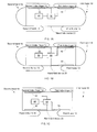
- Figures 1A, 1B, 1C , 2A, 2B , 3A and 3C illustrate various examples of hand-held devices 20 that are contacted by users.
- the following table illustrates the mapping between fingers and sensors (30, 40, 40', 50, 50' 50") that should be contacted by the user, according to various embodiments of the invention.
- Second hand 19 1st index finger 12 1 st thumb 13 2nd index finger 14 2nd thumb 15 1A 40 30 1B 40 50 30 1C 30 50 40 2A 40 50 30 60 2B 40 30 50, 50' 3A 40, 40' 50, 50', 50" 30 60 3B 30 50, 50' 40
- Figure 1A illustrates a hand-held device 20 that is being held by two hands (18 and 19) of a user.
- the hand-held device 20 may include: (a) a first sensor 40 that is positioned such as to be contacted by a first hand 18 of a user when the user holds the hand-held device 20; (b) a second sensor 30 that is positioned such as to be contacted by a second hand 19 of the user when the user holds the hand-held device; and (c) a health monitoring module 90 arranged to process detections signals from the electrodes and from the light detector such as to provide processed signals that are indicative of a state of the user.
- the health monitoring module 90 can perform the entire processing, can perform a partial processing and then send (or assist in sending) the partially processed signals to another entity (such as the main processor of the hand held device, a remote processing entity, a medical hub, a hospital etc) to be further processed.
- the health monitoring module 90 can be dedicated for medical processing or can be also allocated to other tasks.
- the health monitoring module 90 can be a general purpose processor or a digital signals processor, it can control the functionality of the hand-held device 20.
- Either one of the first sensor 40 and the second sensor 30 can be placed on (or embedded with) an edge or a surface of the hand-held device 20 so that once the user touches that edge or surface, the user may touch the first sensor 40.
- Figures 1A and 1B illustrate the first sensor 40 and the second sensor 30 as belonging to a top side of the hand-held device 20 while figure 1C illustrates the first sensor 40 and the second sensor 30 as belonging to a bottom side of the hand-held device 20.
- the first and second sensors 40 and 30 can be located at the same side of the hand-held device 20, can be positioned at different sides and even opposite sides of the hand-held device 20.
- first sensor 40 can be positioned at a top side of the hand-held device 20 while the second sensor 30 can be positioned at a bottom side, a sidewall, a back side or even at the front panel of the hand-held device 20.
- FIG 1A also illustrates the hand-held device 20 as including a man machine interface (MMI) element 80.
- MMI element 80 can be a screen, a keyboard, a microphone, a loudspeaker, a touch screen and the like.
- This MMI element 80 can be much bigger than is being illustrated in Figure 1A . It can span across the entire (or almost entire) hand held device 20.
- one or more sensor is connected to the application processor of the hand held device.
- the MMI element 80 can provide to the user instructions to be followed during the medical test. For example, the MMI element 80 can request a user to contact one or more sensors, to limit the movement of the user, to change position or try to clean an electrode if it is detected that a certain electrode does not receive goon enough (too noisy or too weak) signals, and the like. The MMI element 80 can display or otherwise make the user aware of the outcome of the medical evaluation.
- At least one sensor out of the first sensor 40 and the second sensor 30 can be a hybrid sensor that may include an electrode, an illumination element and a light detector.
- a hybrid sensor denoted 70
- FIGS. 4A-4C and 5A-5C Non-limiting examples of a hybrid sensor (denoted 70) are shown in figures 4A-4C and 5A-5C .
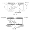
- the hand-held device 20 can include more than two sensors. It can include for example, a third sensor such as third sensor 50 of figures 1B and 1C , 2A, 2b , 3A and 3B .
- the hand-held device 20 can include a fourth sensor, such as fourth sensor 60 of figures 2A , 3A and 50' of figure 3B .
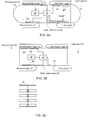
- the hand-held device 20 can include a fifth sensor, such as fifth sensor 40' of figure 3A , can include a sixth sensor such as sixth sensor 50' of figure 3A and can include a seventh sensor such as seventh sensor 50" of figure 3A .
- the number of sensors of the hand-held device can exceed seven.
- the sensors can be positioned such that each sensor is touched by a different finger of the user (as illustrated in figures 1A, 1B, 1C , 2A, 2B ) although multiple sensors can be positioned such as to be touched by the same finger of the user (as illustrated in figures 3A and 3B ).
- the number of sensors that can be touched by the same finger can be two, three or more.
- FIG. 3C illustrates a portion of the hand-held device of any of figures 1A-1C , 2A-2B and 3A-3B , according to an embodiment of the invention.
- Figure 3A illustrates that a sensor (such as second sensor 30) is coupled to the health processing module 90 via analog circuits such as amplifier 92, mixed signal circuits such as analog to digital converter (ADC) 94 and memory unit 96. Electrical detection signals from an electrode of the second sensor 30 are amplified to amplifier 92 to provide amplified detection signals. The amplified detection signals can converted to digital detection signals that can be stored in memory unit 96 and/or processed by health monitoring module 90.
- ADC analog to digital converter
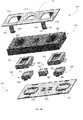
- Figures 4A and 4B are top and side views of a hybrid sensor 70 according to an embodiment of the invention.
- the hybrid sensor 70 includes an electrode 120 that has apertures - light illumination apertures 110(1)- 110(K) and light collection apertures 100(1)-100(N).
- the user or more specifically a finger of the user that touches the electrode (or is positioned above these apertures) is illuminated by light generated by illumination elements 210(1)-210(K) and directed through the light illumination apertures 110(1)- 110(K).
- Light (scattered and/or reflected) from the finger passes through the light collection apertures 100(1)- 100(N) and is detected by light detectors 200(1)- 200(N).
- N and K are positive integers. N may differ from K but N may be equal K.
- the electrode 120 is illustrated as including a conductive portion 120(1) that is supported by another portion 120(2).
- FIGS. 4A and 4C illustrate a linear array of illumination elements and light detectors it is noted that the light detectors and light detectors can be arranged in other manners- for example, as a rectangular array - as illustrated by the two row array of figure 4A .
- the illumination elements and the light detectors can be arranged in an interleaved manner (as illustrated in figures 4A, 4B , 5A , 5B , and 5C ) but can be arranged in other manners.
- Light from an illumination element can be collected by one or more light detectors.
- Figures 5A-5C illustrate a pair of light detectors per a single illumination element but the ratio can differ from 1:2. If there are more than one illumination elements then the number of light detectors associated with a single illumination element can differ from one illumination element to the other or can be equal to each other.
- Figures 5A-5C provide a top view, an exploded view and a cross sectional view of a hybrid sensor 70 according to an embodiment of the invention.
- the hybrid sensor 70 includes: (a) a conductive portion 310 of an electrode, (b) an additional portion 320 of the electrode, (c) protective shields 331 and 332, (d) illumination element 350, (e) light detectors 340 and 360, and (f) electrical circuit 370.
- the electrical circuit 370 can be a rigid or flexible electrical board that provides electrical connectivity (for power supply, control signals and communications) to the illumination element 350 and to light detectors 340 and 360.
- the electrical circuit 370 can be connected to a power supply source and to the health monitoring processor.
- the conductive portion of the electrode 310 is positioned above other parts of the hybrid sensor 70. It has an upper surface 311 that defines a light illumination aperture 313 that is positioned between two light collection apertures 312 and 314.
- the upper surface 311 is connected to four supporting legs, each supporting leg is conductive and include a vertical plate 315 and a horizontal plate 316.
- the horizontal plate 316 can be connected to the board 371 of the electrical circuit 370.
- the electrical circuit 370 can have slits in which each leg can be inserted to that the horizontal plate 316 can be positioned below the board 317 and can be used for assisting in fastening the elements of the hybrid sensor 70 to each other.
- the additional portion 320 of the electrode can provide mechanical support to the conductive portion 310 and can defined spaces (322, 323 and 324) that are positioned below apertures 312, 313 and 314 and allow light to be directed towards the user (through space 323) and be collected (via spaces 322 and 324).
- the additional portion can be made of non-conductive material.
- Protective shields 331 and 332, and light detectors 340 and 360 can be placed within spaces 322 and 324 while illumination element 350 can be placed within space 323.
- Each one of light detectors 340 and 360 and illumination element 350 can conductors (such as 342, 352 and 362) to provide electrical connectivity with conductors (372, 373 and 374) of the board 371.
- the hand-held device 20 can activate one sensor or multiple sensors and can correlate or otherwise use detections signals from one sensor to evaluate detection signals from another sensor.
- the electrode 310 can provide signals that are characterized by a low signal to noise ratio and thus various waveforms such as the QRS complex can be hard to detect.
- the light detector 350 can sense light that is indicative of a movement of the blood vessels of the user that corresponds to the QRS complex and this detection can be used for defining a time window in which to search for the QRS complex at the signals of the electrode.
- the time window is time shifted from the appearance of the QRS complex at the light detector signal due to a known delay between the generation of the RQS complex pulse and appearance of a movement that reflects the blood wave at the user's finger.
- Figure 6 is a flow chart of a method 700 according to an embodiment of the invention.
- Method 700 for monitoring a state of a user may start by stage 710 of receiving detection signals from multiple sensors; wherein the multiple sensors comprise a first sensor that is positioned such as to be contacted by a first hand of a user when the user holds the hand-held device and a second sensor that is positioned such as to be contacted by a second hand of the user when the user holds the hand-held device; wherein at least one sensor of the first sensor and the second sensor is a hybrid sensor that comprises an electrode, an illumination element and a light detector.
- Stage 710 may be followed by stage 720 of processing, by a health monitoring module, the detections signals from at least the electrode and from the light detector such as to provide processed signals that are indicative of a state of the user.
- the hand-held device 20 that executes method 700 can be any of the mentioned above hand-held devices.
- stage 710 can include at least one of the following:
- stage 720 can include at least one of the following:
- Method 700 can include stage 730 of controlling the operation of the electrode and of the illumination elements.
- Stage 730 may include activating the illumination element and the light detector of the hybrid sensor while collecting detection signals from the electrode.
- Stage 730 may include ignoring detection signals from the electrode while measuring a blood oxygen saturation of the user.
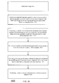
- FIG. 7 illustrates method 800 according to an embodiment of the invention.
- Method 800 may start by stage 810 of processing, by a health monitoring module, detection signals of a light detector of a hybrid sensor to detect a blood vessel movement representative of a QRS complex.
- the hybrid sensor includes one or more electrodes, one or more illumination elements and one or more light detectors.
- Stage 810 is followed by stage 820 of defining, by the health monitoring module, an expected timing of a detection of a QRS complex in the detection signals of the electrode.
- Stage 820 may be followed by stage 830 of searching for the QRS complex in detection signals of the electrode that are detected in proximity to the expected timing of detection.
- a non-limiting example of an execution of method 800 can be found in figure 6 .
- the method may include detecting QRS complexes on ECG signal, detecting pulsing activities on PPG signals, phase matching and at lease zero optimization stages out of (a) optimal estimation of HR for Bradycardia and Tachycardia detection, and (b) Optimal estimation of HRV for AFIB detection.
- the Detection of QRS complexes on ECG signal may include receiving detection signals from one or more electrodes and then differentiating the detection signals in order to get QRS complex slope data.
- the resultant signal (Yn) is compared to a set of adaptive thresholds to make the final decision (together with the noise detection results).
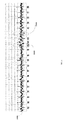
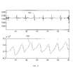
- the detection of pulsing activity on PPG signal may include preprocessing and peak detection.
- the preprocessing may include filtering the PPG signal (for example using a finite impulse response filter with 128 taps between 0.5 and 4 Hz.
- the outcome of this filtering is a filtered signal.
- the filtered signal is represented by line 902 and the PPG signal is represented by curves 901.
- the filtered signal 902 shows a pulsing activity where each pulse corresponds to a single heartbeat.
- the peak detection includes detecting peaks which correspond to each heartbeat. These peaks are identified by testing whether within each N samples the maximum value appears on sample N/2. N is adjusted so small maxima are not found.
- the dots 903 of filtered signal 902 represent some of these peaks. The number of those peaks within a given minute will give the HR in beat per minute (BPM) units,
- Figure9 illustrates an ECG signal 1001.
- a first ellipse 1002 shows a false detection of a QRS complex.
- a second ellipse 1003 shows a missed QRS complex.
- False and negative detections may be are removed by fitting a polynomial model (for example- of a third order3) to the RR sequence.
- the RR sequence is generated by taking the difference in time between two consecutive QRS complexes. A missed QRS complex within the sequence will create a large entry whereas a false detection will create a rather small entry into the sequence.
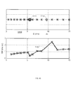
- Figure 10 shows a sequence of detection time for QRS complexes.
- the top graph 1100 shows the timing of each QRS.
- the circle 1111 marks a false detection and the magenta asterisk 1112 corresponds to a false detection (the complex was not found).
- the bottom graph 1120 shows the RR sequence. It is evident that the false detection (1111) leads to a momentary decrease in RR value. The miss detected QRS complex (1112) led to a large value in the RR sequence.
- the method can perform one or more iterations of:
- Stages 1 - 4 can be repeated until no out layers are found.
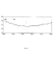
- Figure 12 illustrates an example of a RR sequence 1201 and an estimated RR sequence (eRR) 1202.
- the estimated phase and optimal RR interval can be derived for the remaining sequence of R (after removing lErr and sErr - see above).
- the optimal RR interval can be:
- angle (n) e by the power of (j*2*Pi*R(n)/(RRopt).
- the optimal RR and angle is evaluated or both the QRS complexes and the PPG output.
- the two outputs are then compared.
- L is the likelihood function between a single sample (of Angle PPG ) in this case and the distribution of Angle QRS .
- L X , N u ⁇ ⁇ 1 2 ⁇ ⁇ ⁇ e - X - ⁇ 2 ⁇ ⁇ 2
- FIG 12 illustrates the ECG signal 1301, the PPG 1302, as a function of time. It is evident that every ECG QRS complex matches with a peak in the PPG signal.
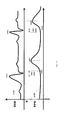
- Figure 13 illustrates filtered ECG and filtered PPG signals according to an embodiment of the invention.
- Curve 1410 represents the filtered ECG signals and it includes two peaks (second points in time) 1411 and 1412.
- Curve 1420 represents the filtered PPG signals and it includes two peaks 1422 and 1523 and two start points (first points in time) 1421 and 1423 that represent the beginning of the pulse.
- This figure shows two PTTs- a first PTT 1401 is the difference between points in time 1411 and 1421 and the second PTT is the difference between points in time 1412 and 1423.
- Figure 14 illustrates filtered ECG, filtered PPG signals and a derivative of the filtered PPG signals according to an embodiment of the invention.
- Curve 1520 represents the filtered ECG signals and it includes peaks (second points in time) such as peak 1521.
- Curve 1510 represents the filtered PPG signals and it includes starts (foots) of pulses (first points in time) such as 1511.
- First point in time 1511 occurs when the value of the derivative of the filtered PPG signals equals zero (at point 1521 of curve 1530).
- a blood pressure indicator can be indicative of a blood pressure of a person including but not limited to a mean blood pressure, a diastolic blood pressure a systolic blood pressure and the like.
- the value of the blood pressure indicator can be the value of the blood pressure of the person or may differ from the value of the blood pressure of the person.
- the value of the blood pressure indicator can represent the pulse transfer time (PTT) of the person.
- PTT pulse transfer time
- the blood pressure can be responsive to various variables in addition to the PTT so that in some cases changes in values of blood pressure indicators may provide an indication of changes in the blood pressure - even if the exact value of the blood pressure is not known.
- Figure 15 illustrates method 1600 for providing a blood pressure indicator according to an embodiment of the invention.
- Method 1600 may start by an initialization stage 1610. During stage 1610 the relationship between the PTT and the blood pressure can be determined. Additionally such information about the relationship between the PTT and the blood pressure can be received. The information can be a mapping function or one or more correlation coefficients.
- Figure 17 illustrates a method 1700 for calibration during which such information can be obtained.
- the initialization stage 1610 may include placing a mobile device in proximity to a person in order to monitor a body area of the person.
- the mobile device may include sensors such as a non-invasive optical plethysmography sensor and a non-invasive Electrocardiography sensor.
- the placement may include allowing a person to contact the mobile phone.
- Stage 1610 may be followed by stage 1620 of obtaining multiple first detection signals from the non-invasive optical plethysmography sensor that monitors a body area of the person and obtaining multiple second detection signals from the non-invasive Electrocardiography sensor.
- Stage 1620 can be executed by any of the devices illustrated above.
- Stage 1620 may be followed by stages 1630 and 1640.
- Stage 1630 may include processing, by a health monitoring module, the multiple first detection signals to detect first points in time that correspond to arrivals of blood pulses to the body area that is monitored by the non-invasive optical plethysmography sensor.
- Stage 1630 may include at least one out of : (a) low-pass filtering the multiple first detection signals to provide multiple first filtered detection signals; (b) calculating a derivative of the first filtered detection signals and detecting the first points in time in response to values of the derivative; (c) calculating the derivative of the first filtered detection signals by applying a least squares parabolic differential filter; (d) detecting first points in time be having a value that is a predetermined fraction (or within a predetermined fraction range) of the maximal value of the maximal filtered first detection signals.
- Stage 1640 may include processing the multiple second detection signals to detect second points in time that correspond to peaks of QRS complexes.
- Stages 1630 and 1640 may be followed by stage 1650 of calculating at least one blood pressure indicator in response to at least one timing difference (PTT) between at least a single pair of first and second points in time that are associated with a same heartbeat.
- PTT timing difference
- Stage 1650 may include at least one of the following stages: (a) calculating a blood pressure indicator per each PTT, (b) calculating a blood pressure indicator per multiple PTTs, (c) comparing different blood pressure indicators to provide an indication of a trend of changes in a blood pressure of the person, (c) calculating the blood pressure indicator in response to at least one correlation coefficient that correlates between one or more PTTs and the one or more PTTs.
- Stage 1650 may be followed by stage 1660 of displaying, storing or communicating the at least one blood pressure indicator.
- Figure 16 illustrates method 1700 according to an embodiment of the invention.
- Method 1700 can be executed randomly, in a pseudo-random manner, in a periodic manner (every few hours, every few days, every few weeks%), in response to events (such as an occurrence of unacceptable measurement errors) and the like.
- Method 1700 may start by stages 1710 and 1720. Stages 1710 and 1720 are executed during a calibration period. According to an embodiment of the invention stages 1710 and 1720 may be repeated for multiple calibration periods.
- Stage 1710 may include obtaining blood pressure measurement results by a blood pressure monitor such as blood pressure monitor that has a cuff.
- Stage 1720 may include obtaining first and second detection signals obtained, during the multiple calibration periods, from a non-invasive optical plethysmography sensor and from a non-invasive Electrocardiography sensor. These non-invasive sensors may belong to mobile device that differs from the blood pressure monitor.
- Stages 1710 and 1720 may be followed by stage 1730 of processing the blood pressure measurement results and the first and second detection signals to determine a relationship between Pulse Transient Time (PTT) values and blood pressure values.
- PTT Pulse Transient Time
- the PTTs are calculated by processing the first and second detection signals while the blood pressure values are taken from the blood pressure measurement results.
- the relationship can be represented by at least one correlation coefficient, by a mapping function and the like.
- the mapping function can be liner or non-linear.
- mapping function includes:
- Stages 1710 and 1720 may be repeated multiple times, over multiple calibration periods and stage 1730 may include (a) stage 1731 of calculating, multiple PTT related values, one PTT related value per calibration period; and (b) stage 1732 of calculating the at least one correlation coefficient by applying a linear regression process on the multiple PTT related values and on the multiple blood pressure measurement results.
- a PTT related value can be the PTT itself, or can be an outcome of processing one or more PTTs obtained during one or more calibration values.
- a single PTT related value can be calculated (during stage 1730) per a single calibration period by a process that may include: (a) selecting (stage 1733) two or more PTTs out of multiple PTTs related to the calibration period, and (b) applying (stage 1734) a function such as an averaging function on the selected two or more PTTs to provide the single PTT related value.
- the selecting may include clustering the PTTs values, and selecting the two or more PTT values that form a cluster that includes PTT values that are relatively close to each other.
- the selecting may include ignoring PTTs if their values is outside an allowable range of timing difference values.
- Figure 17 illustrates method 1800 according to an embodiment of the invention.
- Method 1800 may start by initialization stage 1810 that may resemble stage 1610 of method 1600.
- Stage 1810 may be followed by stage 1820 of obtaining multiple first detection signals from a non-invasive optical plethysmography sensor that monitors a body area of the person and obtaining multiple second detection signals from a non-invasive Electrocardiography sensor.
- the non-invasive optical plethysmography sensor and the non-invasive Electrocardiography sensor belong to a mobile device.
- Stage 1810 may include calculating the mapping function based upon blood pressure measurement results obtained by a blood pressure monitor that differs from the mobile device. Stage 1810 may include any of the stages of method 1700.
- the mapping function can be a linear or non-linear mapping function.
- Stage 1820 may be followed by stage 1830 of calculating, by the mobile device, multiple pulse transfer times in response to the first and second detection signals.
- Stage 1830 may be followed by stage 1840 of applying a mapping function on at least one pulse transfer time to provide at least one value of the blood pressure of the person.
- Stage 1820 may include processing the multiple first detection signals to detect first points in time that correspond to arrivals of blood pulses to the body area that is monitored by the non-invasive optical plethysmography sensor; processing the multiple second detection signals to detect second points in time that correspond to peaks of QRS complexes; and calculating at least one timing difference between at least a single pair of first and second points in time that are associated with a same heartbeat.
- Stage 1820 may include processing the first and second detection signals to find points in time that differ from the first points and the second points in time.
- Non-transitory computer readable medium that can store instructions for executing any of the mentioned above methods or any combination of any two or more stages of any of the mentioned above methods.
- the invention may also be implemented in a computer program for running on a computer system, at least including code portions for performing steps of a method according to the invention when run on a programmable apparatus, such as a computer system or enabling a programmable apparatus to perform functions of a device or system according to the invention.
- a computer program is a list of instructions such as a particular application program and/or an operating system.
- the computer program may for instance include one or more of: a subroutine, a function, a procedure, an object method, an object implementation, an executable application, an applet, a servlet, a source code, an object code, a shared library/dynamic load library and/or other sequence of instructions designed for execution on a computer system.
- the computer program may be stored internally on a non-transitory computer readable medium. All or some of the computer program may be provided on computer readable media permanently, removably or remotely coupled to an information processing system.
- the computer readable media may include, for example and without limitation, any number of the following: magnetic storage media including disk and tape storage media; optical storage media such as compact disk media (e.g., CD-ROM, CD-R, etc.) and digital video disk storage media; nonvolatile memory storage media including semiconductor-based memory units such as FLASH memory, EEPROM, EPROM, ROM; ferromagnetic digital memories; MRAM; volatile storage media including registers, buffers or caches, main memory, RAM, etc.
- a computer process typically includes an executing (running) program or portion of a program, current program values and state information, and the resources used by the operating system to manage the execution of the process.
- An operating system is the software that manages the sharing of the resources of a computer and provides programmers with an interface used to access those resources.
- An operating system processes system data and user input, and responds by allocating and managing tasks and internal system resources as a service to users and programs of the system.
- the computer system may for instance include at least one processing unit, associated memory and a number of input/output (I/O) devices.
- I/O input/output
- the computer system processes information according to the computer program and produces resultant output information via I/O devices.
- connections as discussed herein may be any type of connection suitable to transfer signals from or to the respective nodes, units or devices, for example via intermediate devices. Accordingly, unless implied or stated otherwise, the connections may for example be direct connections or indirect connections.
- the connections may be illustrated or described in reference to being a single connection, a plurality of connections, unidirectional connections, or bidirectional connections. However, different embodiments may vary the implementation of the connections. For example, separate unidirectional connections may be used rather than bidirectional connections and vice versa.
- plurality of connections may be replaced with a single connection that transfers multiple signals serially or in a time multiplexed manner. Likewise, single connections carrying multiple signals may be separated out into various different connections carrying subsets of these signals. Therefore, many options exist for transferring signals.
- Each signal described herein may be designed as positive or negative logic.
- the signal In the case of a negative logic signal, the signal is active low where the logically true state corresponds to a logic level zero.
- the signal In the case of a positive logic signal, the signal is active high where the logically true state corresponds to a logic level one.
- any of the signals described herein may be designed as either negative or positive logic signals. Therefore, in alternate embodiments, those signals described as positive logic signals may be implemented as negative logic signals, and those signals described as negative logic signals may be implemented as positive logic signals.
- assert or “set” and “negate” (or “deassert” or “clear”) are used herein when referring to the rendering of a signal, status bit, or similar apparatus into its logically true or logically false state, respectively. If the logically true state is a logic level one, the logically false state is a logic level zero. And if the logically true state is a logic level zero, the logically false state is a logic level one.
- logic blocks are merely illustrative and that alternative embodiments may merge logic blocks or circuit elements or impose an alternate decomposition of functionality upon various logic blocks or circuit elements.
- architectures depicted herein are merely exemplary, and that in fact many other architectures may be implemented which achieve the same functionality.
- any arrangement of components to achieve the same functionality is effectively “associated” such that the desired functionality is achieved.
- any two components herein combined to achieve a particular functionality may be seen as “associated with” each other such that the desired functionality is achieved, irrespective of architectures or intermedial components.
- any two components so associated can also be viewed as being “operably connected,” or “operably coupled,” to each other to achieve the desired functionality.
- the illustrated examples may be implemented as circuitry located on a single integrated circuit or within a same device.
- the examples may be implemented as any number of separate integrated circuits or separate devices interconnected with each other in a suitable manner.
- the examples, or portions thereof may implemented as soft or code representations of physical circuitry or of logical representations convertible into physical circuitry, such as in a hardware description language of any appropriate type.
- the invention is not limited to physical devices or units implemented in non-programmable hardware but can also be applied in programmable devices or units able to perform the desired device functions by operating in accordance with suitable program code, such as mainframes, minicomputers, servers, workstations, personal computers, notepads, personal digital assistants, electronic games, automotive and other embedded systems, cell phones and various other wireless devices, commonly denoted in this application as 'computer systems'.
- suitable program code such as mainframes, minicomputers, servers, workstations, personal computers, notepads, personal digital assistants, electronic games, automotive and other embedded systems, cell phones and various other wireless devices, commonly denoted in this application as 'computer systems'.
- any reference signs placed between parentheses shall not be construed as limiting the claim.
- the word 'comprising' does not exclude the presence of other elements or steps then those listed in a claim.
- the terms "a” or "an,” as used herein, are defined as one or more than one.
Landscapes
- Health & Medical Sciences (AREA)
- Life Sciences & Earth Sciences (AREA)
- Cardiology (AREA)
- Physics & Mathematics (AREA)
- Engineering & Computer Science (AREA)
- Molecular Biology (AREA)
- Animal Behavior & Ethology (AREA)
- Pathology (AREA)
- Veterinary Medicine (AREA)
- Biomedical Technology (AREA)
- Heart & Thoracic Surgery (AREA)
- Medical Informatics (AREA)
- Public Health (AREA)
- Surgery (AREA)
- Biophysics (AREA)
- General Health & Medical Sciences (AREA)
- Physiology (AREA)
- Vascular Medicine (AREA)
- Spectroscopy & Molecular Physics (AREA)
- Optics & Photonics (AREA)
- Artificial Intelligence (AREA)
- Computer Vision & Pattern Recognition (AREA)
- Psychiatry (AREA)
- Signal Processing (AREA)
- Measuring Pulse, Heart Rate, Blood Pressure Or Blood Flow (AREA)
Priority Applications (2)
| Application Number | Priority Date | Filing Date | Title |
|---|---|---|---|
| DK16002744.7T DK3205263T3 (da) | 2012-03-29 | 2013-04-02 | Blodtryksestimation ved hjælp af håndholdt apparat |
| EP16002744.7A EP3205263B1 (fr) | 2012-03-29 | 2013-04-02 | Estimation de pression sanguine à l'aide d'un dispositif à main |
Applications Claiming Priority (2)
| Application Number | Priority Date | Filing Date | Title |
|---|---|---|---|
| US13/433,608 US9693697B2 (en) | 2012-03-29 | 2012-03-29 | Hand-held device having health monitoring capabilities |
| US13/733,235 US20140031646A1 (en) | 2012-03-29 | 2013-01-03 | Blood pressure estimation using a hand-held device |
Related Child Applications (1)
| Application Number | Title | Priority Date | Filing Date |
|---|---|---|---|
| EP16002744.7A Division EP3205263B1 (fr) | 2012-03-29 | 2013-04-02 | Estimation de pression sanguine à l'aide d'un dispositif à main |
Publications (2)
| Publication Number | Publication Date |
|---|---|
| EP2644089A1 true EP2644089A1 (fr) | 2013-10-02 |
| EP2644089B1 EP2644089B1 (fr) | 2016-12-28 |
Family
ID=48047861
Family Applications (2)
| Application Number | Title | Priority Date | Filing Date |
|---|---|---|---|
| EP16002744.7A Active EP3205263B1 (fr) | 2012-03-29 | 2013-04-02 | Estimation de pression sanguine à l'aide d'un dispositif à main |
| EP13161986.8A Active EP2644089B1 (fr) | 2012-03-29 | 2013-04-02 | Estimation de pression sanguine à l'aide d'un dispositif à main |
Family Applications Before (1)
| Application Number | Title | Priority Date | Filing Date |
|---|---|---|---|
| EP16002744.7A Active EP3205263B1 (fr) | 2012-03-29 | 2013-04-02 | Estimation de pression sanguine à l'aide d'un dispositif à main |
Country Status (4)
| Country | Link |
|---|---|
| US (1) | US20140031646A1 (fr) |
| EP (2) | EP3205263B1 (fr) |
| DK (2) | DK2644089T3 (fr) |
| WO (1) | WO2013144968A1 (fr) |
Cited By (4)
| Publication number | Priority date | Publication date | Assignee | Title |
|---|---|---|---|---|
| WO2015061166A1 (fr) * | 2013-10-25 | 2015-04-30 | Qualcomm Incorporated | Système et procédé d'obtention de mesures de fonctions corporelles au moyen d'un dispositif mobile |
| WO2015061783A1 (fr) * | 2013-10-25 | 2015-04-30 | Qualcomm Incorporated | Système et procédé pour obtenir des mesures de fonctions corporelles à l'aide d'un dispositif mobile |
| WO2016035441A1 (fr) * | 2014-09-03 | 2016-03-10 | オムロンヘルスケア株式会社 | Dispositif de régulation de débit et appareil de mesure de pression artérielle |
| WO2017028011A1 (fr) * | 2015-08-14 | 2017-02-23 | 华为技术有限公司 | Procédé et dispositif de traitement de données de mesure de pression sanguine |
Families Citing this family (12)
| Publication number | Priority date | Publication date | Assignee | Title |
|---|---|---|---|---|
| US8983583B2 (en) | 2006-10-18 | 2015-03-17 | Medicomp, Inc. | Cardiac event monitoring system |
| WO2015171764A1 (fr) | 2014-05-06 | 2015-11-12 | Alivecor, Inc. | Dispositif de surveillance de la tension artérielle |
| EP3087915B1 (fr) | 2015-04-27 | 2022-02-09 | Tata Consultancy Services Limited | Procédé et système de nettoyage de bruit de signaux photopléthysmographiques pour d'estimation de pression du sang |
| WO2017088156A1 (fr) * | 2015-11-26 | 2017-06-01 | 华为技术有限公司 | Procédé de mesure de paramètre de pression sanguine et équipement destiné à un utilisateur |
| US11051765B2 (en) * | 2015-12-31 | 2021-07-06 | Shanghai Oxi Technology Co., Ltd | Health status detecting system and method for detecting health status |
| US20170262987A1 (en) * | 2016-03-09 | 2017-09-14 | Xerox Corporation | Method and apparatus for non-contact estimation of pulse transmit time |
| US10722125B2 (en) * | 2016-10-31 | 2020-07-28 | Livemetric (Medical) S.A. | Blood pressure signal acquisition using a pressure sensor array |
| US10524776B2 (en) * | 2016-11-08 | 2020-01-07 | Arthrex, Inc. | Soft suture anchor assembly with barbed suture and attached tissue fixation disk |
| EP3366203B1 (fr) | 2017-02-23 | 2019-12-25 | Tata Consultancy Services Limited | Procédé et système d'estimation de la pression artérielle sans brassard faisant appel aux caractéristiques du photopléthysmogramme et au temps de transit du pouls |
| US20210137386A1 (en) * | 2018-09-14 | 2021-05-13 | Anhui Huami Information Technology Co., Ltd. | Photoplethysmograph device and electronic apparatus |
| CN114305358B (zh) * | 2021-02-24 | 2023-04-14 | 心永(北京)科技有限公司 | 血压测量模型的标定方法、装置、计算机设备和存储介质 |
| CN115211851A (zh) * | 2022-07-27 | 2022-10-21 | 北京超思电子技术有限责任公司 | 测量设备、方法及存储介质 |
Citations (9)
| Publication number | Priority date | Publication date | Assignee | Title |
|---|---|---|---|---|
| EP0821910A2 (fr) * | 1996-08-01 | 1998-02-04 | Colin Corporation | Appareil de surveillance de la pression sanguine |
| US20050261593A1 (en) * | 2004-05-20 | 2005-11-24 | Zhang Yuan T | Methods for measuring blood pressure with automatic compensations |
| US20070185393A1 (en) * | 2006-02-03 | 2007-08-09 | Triage Wireless, Inc. | System for measuring vital signs using an optical module featuring a green light source |
| EP1977688A2 (fr) * | 2007-04-04 | 2008-10-08 | LG Electronics Inc. | Appareil et procédé de surveillance de la pression artérielle |
| US20100081946A1 (en) * | 2008-09-26 | 2010-04-01 | Qualcomm Incorporated | Method and apparatus for non-invasive cuff-less blood pressure estimation using pulse arrival time and heart rate with adaptive calibration |
| US20100160798A1 (en) * | 2007-06-12 | 2010-06-24 | Sotera Wireless, Inc. | BODY-WORN SYSTEM FOR MEASURING CONTINUOUS NON-INVASIVE BLOOD PRESSURE (cNIBP) |
| US20100160793A1 (en) * | 2008-12-23 | 2010-06-24 | Industrial Technology Research Institute | Biosignal measurement modules and methods |
| WO2010087986A2 (fr) * | 2009-01-30 | 2010-08-05 | Simpkins Cuthbert O | Fluide de ressuscitation |
| US20100222652A1 (en) * | 2007-09-07 | 2010-09-02 | Ok Kyung Cho | Diagnostic sensor unit |
Family Cites Families (10)
| Publication number | Priority date | Publication date | Assignee | Title |
|---|---|---|---|---|
| JPH0532082Y2 (fr) * | 1988-07-26 | 1993-08-18 | ||
| US5316008A (en) * | 1990-04-06 | 1994-05-31 | Casio Computer Co., Ltd. | Measurement of electrocardiographic wave and sphygmus |
| JP3213278B2 (ja) * | 1998-05-12 | 2001-10-02 | 日本コーリン株式会社 | 非観血連続血圧推定装置 |
| WO2001054575A1 (fr) * | 2000-01-26 | 2001-08-02 | Vsm Medtech Ltd. | Procede et appareil de controle continu de la pression arterielle |
| EP1388321A1 (fr) * | 2002-08-09 | 2004-02-11 | Instrumentarium Oyj | Procédé et systeme de mesure continue et non invasive de la pression sanguine |
| JP2008536545A (ja) * | 2005-03-21 | 2008-09-11 | ヘルス−スマート リミテッド | 連続血圧モニタリングのためのシステム |
| US8574162B2 (en) * | 2008-06-30 | 2013-11-05 | Nellcor Puritan Bennett Ireland | Systems and methods for detecting pulses |
| US8313439B2 (en) * | 2009-03-20 | 2012-11-20 | Massachusetts Institute Of Technology | Calibration of pulse transit time measurements to arterial blood pressure using external arterial pressure applied along the pulse transit path |
| CA2780005A1 (fr) * | 2009-11-12 | 2011-05-19 | Nellcor Puritan Bennett Llc | Systemes et procedes pour capteurs physiologiques combines |
| EP2347706A1 (fr) * | 2010-01-14 | 2011-07-27 | Microlife Intellectual Property GmbH | Dispositif et procédé pour mesurer la tension artérielle |
-
2013
- 2013-01-03 US US13/733,235 patent/US20140031646A1/en not_active Abandoned
- 2013-04-02 EP EP16002744.7A patent/EP3205263B1/fr active Active
- 2013-04-02 EP EP13161986.8A patent/EP2644089B1/fr active Active
- 2013-04-02 DK DK13161986.8T patent/DK2644089T3/en active
- 2013-04-02 WO PCT/IL2013/050302 patent/WO2013144968A1/fr active Application Filing
- 2013-04-02 DK DK16002744.7T patent/DK3205263T3/da active
Patent Citations (9)
| Publication number | Priority date | Publication date | Assignee | Title |
|---|---|---|---|---|
| EP0821910A2 (fr) * | 1996-08-01 | 1998-02-04 | Colin Corporation | Appareil de surveillance de la pression sanguine |
| US20050261593A1 (en) * | 2004-05-20 | 2005-11-24 | Zhang Yuan T | Methods for measuring blood pressure with automatic compensations |
| US20070185393A1 (en) * | 2006-02-03 | 2007-08-09 | Triage Wireless, Inc. | System for measuring vital signs using an optical module featuring a green light source |
| EP1977688A2 (fr) * | 2007-04-04 | 2008-10-08 | LG Electronics Inc. | Appareil et procédé de surveillance de la pression artérielle |
| US20100160798A1 (en) * | 2007-06-12 | 2010-06-24 | Sotera Wireless, Inc. | BODY-WORN SYSTEM FOR MEASURING CONTINUOUS NON-INVASIVE BLOOD PRESSURE (cNIBP) |
| US20100222652A1 (en) * | 2007-09-07 | 2010-09-02 | Ok Kyung Cho | Diagnostic sensor unit |
| US20100081946A1 (en) * | 2008-09-26 | 2010-04-01 | Qualcomm Incorporated | Method and apparatus for non-invasive cuff-less blood pressure estimation using pulse arrival time and heart rate with adaptive calibration |
| US20100160793A1 (en) * | 2008-12-23 | 2010-06-24 | Industrial Technology Research Institute | Biosignal measurement modules and methods |
| WO2010087986A2 (fr) * | 2009-01-30 | 2010-08-05 | Simpkins Cuthbert O | Fluide de ressuscitation |
Non-Patent Citations (1)
| Title |
|---|
| FREI ET AL: "Least squares acceleration filtering for the estimation of signal derivatives and sharpness at extrema [and application to biological signals]", IEEE TRANSACTIONS ON BIOMEDICAL ENGINEERING, vol. 46, no. 8, 1 January 1999 (1999-01-01), pages 971 - 977, XP055065235, ISSN: 0018-9294, DOI: 10.1109/10.775407 * |
Cited By (17)
| Publication number | Priority date | Publication date | Assignee | Title |
|---|---|---|---|---|
| US10694957B2 (en) | 2013-10-25 | 2020-06-30 | Qualcomm Incorporated | System and method for obtaining bodily function measurements using a mobile device |
| JP2016537063A (ja) * | 2013-10-25 | 2016-12-01 | クアルコム,インコーポレイテッド | モバイルデバイスを用いて身体機能測定値を得るためのシステムおよび方法 |
| US11931132B2 (en) | 2013-10-25 | 2024-03-19 | Qualcomm Incorporated | System and method for obtaining bodily function measurements using a mobile device |
| US11918323B2 (en) | 2013-10-25 | 2024-03-05 | Qualcomm Incorporated | System and method for obtaining bodily function measurements using a mobile device |
| US10052035B2 (en) | 2013-10-25 | 2018-08-21 | Qualcomm Incorporated | System and method for obtaining bodily function measurements using a mobile device |
| WO2015061783A1 (fr) * | 2013-10-25 | 2015-04-30 | Qualcomm Incorporated | Système et procédé pour obtenir des mesures de fonctions corporelles à l'aide d'un dispositif mobile |
| WO2015061166A1 (fr) * | 2013-10-25 | 2015-04-30 | Qualcomm Incorporated | Système et procédé d'obtention de mesures de fonctions corporelles au moyen d'un dispositif mobile |
| US10478075B2 (en) | 2013-10-25 | 2019-11-19 | Qualcomm Incorporated | System and method for obtaining bodily function measurements using a mobile device |
| US11020012B2 (en) | 2014-09-03 | 2021-06-01 | Omron Healthcare Co., Ltd. | Flow rate control apparatus and blood pressure monitor |
| WO2016035441A1 (fr) * | 2014-09-03 | 2016-03-10 | オムロンヘルスケア株式会社 | Dispositif de régulation de débit et appareil de mesure de pression artérielle |
| CN106795976B (zh) * | 2014-09-03 | 2019-05-28 | 欧姆龙健康医疗事业株式会社 | 流量控制装置以及血压计 |
| CN106795976A (zh) * | 2014-09-03 | 2017-05-31 | 欧姆龙健康医疗事业株式会社 | 流量控制装置以及血压计 |
| JP2016053394A (ja) * | 2014-09-03 | 2016-04-14 | オムロンヘルスケア株式会社 | 流量制御装置および血圧計 |
| CN107072555A (zh) * | 2015-08-14 | 2017-08-18 | 华为技术有限公司 | 一种血压测量数据的处理方法及装置 |
| WO2017028011A1 (fr) * | 2015-08-14 | 2017-02-23 | 华为技术有限公司 | Procédé et dispositif de traitement de données de mesure de pression sanguine |
| CN107072555B (zh) * | 2015-08-14 | 2021-10-01 | 华为技术有限公司 | 一种血压测量数据的校准方法及装置 |
| US20180078156A1 (en) * | 2015-08-14 | 2018-03-22 | Huawei Technologies Co., Ltd. | Blood Pressure Measurement Data Processing Method and Apparatus |
Also Published As
| Publication number | Publication date |
|---|---|
| DK2644089T3 (en) | 2017-03-20 |
| WO2013144968A1 (fr) | 2013-10-03 |
| DK3205263T3 (da) | 2019-08-19 |
| EP3205263A1 (fr) | 2017-08-16 |
| EP2644089B1 (fr) | 2016-12-28 |
| US20140031646A1 (en) | 2014-01-30 |
| EP3205263B1 (fr) | 2019-06-19 |
Similar Documents
| Publication | Publication Date | Title |
|---|---|---|
| EP3205263B1 (fr) | Estimation de pression sanguine à l'aide d'un dispositif à main | |
| US10631742B2 (en) | Hand-held device having health monitoring capabilities | |
| US11931132B2 (en) | System and method for obtaining bodily function measurements using a mobile device | |
| US10531808B2 (en) | Method of detecting the wearing limb of a wearable electronic device | |
| Chowdhury et al. | Real-time robust heart rate estimation from wrist-type PPG signals using multiple reference adaptive noise cancellation | |
| US10052035B2 (en) | System and method for obtaining bodily function measurements using a mobile device | |
| Shirmohammadi et al. | Instrumentation and measurement in medical, biomedical, and healthcare systems | |
| CN100518630C (zh) | 指环式生理信息监测装置 | |
| RU2683205C1 (ru) | Система и способ электрокардиографического мониторинга | |
| Yang et al. | Estimation and validation of arterial blood pressure using photoplethysmogram morphology features in conjunction with pulse arrival time in large open databases | |
| KR101536361B1 (ko) | 심전도 신호 분석 방법 및 그를 이용한 심전도 장치 | |
| CN109998498A (zh) | 电子设备 | |
| Yu et al. | An unobtrusive stress recognition system for the smart office | |
| CN111419219A (zh) | Ppg心搏信号的预处理方法、装置及房颤检测设备 | |
| US10433745B1 (en) | Handheld ECG monitoring system with fault detection | |
| CN210697620U (zh) | 一种全自动穿戴式心血管健康诊断手环 | |
| US20170164856A1 (en) | Sensing of a user's physiological context using a hand-held device | |
| WO2020100135A2 (fr) | Système de surveillance d'ecg portatif avec détection de défaillance |
Legal Events
| Date | Code | Title | Description |
|---|---|---|---|
| PUAI | Public reference made under article 153(3) epc to a published international application that has entered the european phase |
Free format text: ORIGINAL CODE: 0009012 |
|
| AK | Designated contracting states |
Kind code of ref document: A1 Designated state(s): AL AT BE BG CH CY CZ DE DK EE ES FI FR GB GR HR HU IE IS IT LI LT LU LV MC MK MT NL NO PL PT RO RS SE SI SK SM TR |
|
| AX | Request for extension of the european patent |
Extension state: BA ME |
|
| 17P | Request for examination filed |
Effective date: 20140331 |
|
| RBV | Designated contracting states (corrected) |
Designated state(s): AL AT BE BG CH CY CZ DE DK EE ES FI FR GB GR HR HU IE IS IT LI LT LU LV MC MK MT NL NO PL PT RO RS SE SI SK SM TR |
|
| 17Q | First examination report despatched |
Effective date: 20141126 |
|
| GRAP | Despatch of communication of intention to grant a patent |
Free format text: ORIGINAL CODE: EPIDOSNIGR1 |
|
| INTG | Intention to grant announced |
Effective date: 20160711 |
|
| GRAS | Grant fee paid |
Free format text: ORIGINAL CODE: EPIDOSNIGR3 |
|
| GRAA | (expected) grant |
Free format text: ORIGINAL CODE: 0009210 |
|
| AK | Designated contracting states |
Kind code of ref document: B1 Designated state(s): AL AT BE BG CH CY CZ DE DK EE ES FI FR GB GR HR HU IE IS IT LI LT LU LV MC MK MT NL NO PL PT RO RS SE SI SK SM TR |
|
| REG | Reference to a national code |
Ref country code: GB Ref legal event code: FG4D |
|
| REG | Reference to a national code |
Ref country code: CH Ref legal event code: EP |
|
| REG | Reference to a national code |
Ref country code: AT Ref legal event code: REF Ref document number: 856601 Country of ref document: AT Kind code of ref document: T Effective date: 20170115 |
|
| REG | Reference to a national code |
Ref country code: IE Ref legal event code: FG4D |
|
| REG | Reference to a national code |
Ref country code: DE Ref legal event code: R096 Ref document number: 602013015797 Country of ref document: DE |
|
| PG25 | Lapsed in a contracting state [announced via postgrant information from national office to epo] |
Ref country code: LV Free format text: LAPSE BECAUSE OF FAILURE TO SUBMIT A TRANSLATION OF THE DESCRIPTION OR TO PAY THE FEE WITHIN THE PRESCRIBED TIME-LIMIT Effective date: 20161228 |
|
| REG | Reference to a national code |
Ref country code: CH Ref legal event code: NV Representative=s name: RIEDERER HASLER AND PARTNER PATENTANWAELTE AG, CH |
|
| REG | Reference to a national code |
Ref country code: DK Ref legal event code: T3 Effective date: 20170315 |
|
| REG | Reference to a national code |
Ref country code: SE Ref legal event code: TRGR |
|
| REG | Reference to a national code |
Ref country code: NL Ref legal event code: FP |
|
| REG | Reference to a national code |
Ref country code: LT Ref legal event code: MG4D |
|
| PG25 | Lapsed in a contracting state [announced via postgrant information from national office to epo] |
Ref country code: GR Free format text: LAPSE BECAUSE OF FAILURE TO SUBMIT A TRANSLATION OF THE DESCRIPTION OR TO PAY THE FEE WITHIN THE PRESCRIBED TIME-LIMIT Effective date: 20170329 Ref country code: LT Free format text: LAPSE BECAUSE OF FAILURE TO SUBMIT A TRANSLATION OF THE DESCRIPTION OR TO PAY THE FEE WITHIN THE PRESCRIBED TIME-LIMIT Effective date: 20161228 |
|
| REG | Reference to a national code |
Ref country code: NO Ref legal event code: T2 Effective date: 20161228 |
|
| PG25 | Lapsed in a contracting state [announced via postgrant information from national office to epo] |
Ref country code: RS Free format text: LAPSE BECAUSE OF FAILURE TO SUBMIT A TRANSLATION OF THE DESCRIPTION OR TO PAY THE FEE WITHIN THE PRESCRIBED TIME-LIMIT Effective date: 20161228 Ref country code: HR Free format text: LAPSE BECAUSE OF FAILURE TO SUBMIT A TRANSLATION OF THE DESCRIPTION OR TO PAY THE FEE WITHIN THE PRESCRIBED TIME-LIMIT Effective date: 20161228 |
|
| PG25 | Lapsed in a contracting state [announced via postgrant information from national office to epo] |
Ref country code: RO Free format text: LAPSE BECAUSE OF FAILURE TO SUBMIT A TRANSLATION OF THE DESCRIPTION OR TO PAY THE FEE WITHIN THE PRESCRIBED TIME-LIMIT Effective date: 20161228 Ref country code: CZ Free format text: LAPSE BECAUSE OF FAILURE TO SUBMIT A TRANSLATION OF THE DESCRIPTION OR TO PAY THE FEE WITHIN THE PRESCRIBED TIME-LIMIT Effective date: 20161228 Ref country code: EE Free format text: LAPSE BECAUSE OF FAILURE TO SUBMIT A TRANSLATION OF THE DESCRIPTION OR TO PAY THE FEE WITHIN THE PRESCRIBED TIME-LIMIT Effective date: 20161228 Ref country code: IS Free format text: LAPSE BECAUSE OF FAILURE TO SUBMIT A TRANSLATION OF THE DESCRIPTION OR TO PAY THE FEE WITHIN THE PRESCRIBED TIME-LIMIT Effective date: 20170428 Ref country code: SK Free format text: LAPSE BECAUSE OF FAILURE TO SUBMIT A TRANSLATION OF THE DESCRIPTION OR TO PAY THE FEE WITHIN THE PRESCRIBED TIME-LIMIT Effective date: 20161228 |
|
| PG25 | Lapsed in a contracting state [announced via postgrant information from national office to epo] |
Ref country code: IT Free format text: LAPSE BECAUSE OF FAILURE TO SUBMIT A TRANSLATION OF THE DESCRIPTION OR TO PAY THE FEE WITHIN THE PRESCRIBED TIME-LIMIT Effective date: 20161228 Ref country code: PT Free format text: LAPSE BECAUSE OF FAILURE TO SUBMIT A TRANSLATION OF THE DESCRIPTION OR TO PAY THE FEE WITHIN THE PRESCRIBED TIME-LIMIT Effective date: 20170428 Ref country code: ES Free format text: LAPSE BECAUSE OF FAILURE TO SUBMIT A TRANSLATION OF THE DESCRIPTION OR TO PAY THE FEE WITHIN THE PRESCRIBED TIME-LIMIT Effective date: 20161228 Ref country code: BG Free format text: LAPSE BECAUSE OF FAILURE TO SUBMIT A TRANSLATION OF THE DESCRIPTION OR TO PAY THE FEE WITHIN THE PRESCRIBED TIME-LIMIT Effective date: 20170328 Ref country code: SM Free format text: LAPSE BECAUSE OF FAILURE TO SUBMIT A TRANSLATION OF THE DESCRIPTION OR TO PAY THE FEE WITHIN THE PRESCRIBED TIME-LIMIT Effective date: 20161228 Ref country code: PL Free format text: LAPSE BECAUSE OF FAILURE TO SUBMIT A TRANSLATION OF THE DESCRIPTION OR TO PAY THE FEE WITHIN THE PRESCRIBED TIME-LIMIT Effective date: 20161228 |
|
| REG | Reference to a national code |
Ref country code: DE Ref legal event code: R097 Ref document number: 602013015797 Country of ref document: DE |
|
| PLBE | No opposition filed within time limit |
Free format text: ORIGINAL CODE: 0009261 |
|
| STAA | Information on the status of an ep patent application or granted ep patent |
Free format text: STATUS: NO OPPOSITION FILED WITHIN TIME LIMIT |
|
| 26N | No opposition filed |
Effective date: 20170929 |
|
| REG | Reference to a national code |
Ref country code: IE Ref legal event code: MM4A |
|
| REG | Reference to a national code |
Ref country code: FR Ref legal event code: ST Effective date: 20171229 |
|
| PG25 | Lapsed in a contracting state [announced via postgrant information from national office to epo] |
Ref country code: MC Free format text: LAPSE BECAUSE OF FAILURE TO SUBMIT A TRANSLATION OF THE DESCRIPTION OR TO PAY THE FEE WITHIN THE PRESCRIBED TIME-LIMIT Effective date: 20161228 Ref country code: FR Free format text: LAPSE BECAUSE OF NON-PAYMENT OF DUE FEES Effective date: 20170502 |
|
| PG25 | Lapsed in a contracting state [announced via postgrant information from national office to epo] |
Ref country code: LU Free format text: LAPSE BECAUSE OF NON-PAYMENT OF DUE FEES Effective date: 20170402 Ref country code: SI Free format text: LAPSE BECAUSE OF FAILURE TO SUBMIT A TRANSLATION OF THE DESCRIPTION OR TO PAY THE FEE WITHIN THE PRESCRIBED TIME-LIMIT Effective date: 20161228 |
|
| PG25 | Lapsed in a contracting state [announced via postgrant information from national office to epo] |
Ref country code: IE Free format text: LAPSE BECAUSE OF NON-PAYMENT OF DUE FEES Effective date: 20170402 |
|
| PG25 | Lapsed in a contracting state [announced via postgrant information from national office to epo] |
Ref country code: MT Free format text: LAPSE BECAUSE OF NON-PAYMENT OF DUE FEES Effective date: 20170402 |
|
| PG25 | Lapsed in a contracting state [announced via postgrant information from national office to epo] |
Ref country code: HU Free format text: LAPSE BECAUSE OF FAILURE TO SUBMIT A TRANSLATION OF THE DESCRIPTION OR TO PAY THE FEE WITHIN THE PRESCRIBED TIME-LIMIT; INVALID AB INITIO Effective date: 20130402 |
|
| PG25 | Lapsed in a contracting state [announced via postgrant information from national office to epo] |
Ref country code: CY Free format text: LAPSE BECAUSE OF NON-PAYMENT OF DUE FEES Effective date: 20161228 |
|
| PG25 | Lapsed in a contracting state [announced via postgrant information from national office to epo] |
Ref country code: MK Free format text: LAPSE BECAUSE OF FAILURE TO SUBMIT A TRANSLATION OF THE DESCRIPTION OR TO PAY THE FEE WITHIN THE PRESCRIBED TIME-LIMIT Effective date: 20161228 |
|
| PG25 | Lapsed in a contracting state [announced via postgrant information from national office to epo] |
Ref country code: TR Free format text: LAPSE BECAUSE OF FAILURE TO SUBMIT A TRANSLATION OF THE DESCRIPTION OR TO PAY THE FEE WITHIN THE PRESCRIBED TIME-LIMIT Effective date: 20161228 |
|
| REG | Reference to a national code |
Ref country code: AT Ref legal event code: UEP Ref document number: 856601 Country of ref document: AT Kind code of ref document: T Effective date: 20161228 |
|
| PG25 | Lapsed in a contracting state [announced via postgrant information from national office to epo] |
Ref country code: AL Free format text: LAPSE BECAUSE OF FAILURE TO SUBMIT A TRANSLATION OF THE DESCRIPTION OR TO PAY THE FEE WITHIN THE PRESCRIBED TIME-LIMIT Effective date: 20161228 |
|
| PGFP | Annual fee paid to national office [announced via postgrant information from national office to epo] |
Ref country code: NL Payment date: 20240425 Year of fee payment: 12 |
|
| PGFP | Annual fee paid to national office [announced via postgrant information from national office to epo] |
Ref country code: GB Payment date: 20240423 Year of fee payment: 12 |
|
| PGFP | Annual fee paid to national office [announced via postgrant information from national office to epo] |
Ref country code: DE Payment date: 20240429 Year of fee payment: 12 |
|
| PGFP | Annual fee paid to national office [announced via postgrant information from national office to epo] |
Ref country code: DK Payment date: 20240425 Year of fee payment: 12 |
|
| PGFP | Annual fee paid to national office [announced via postgrant information from national office to epo] |
Ref country code: CH Payment date: 20240501 Year of fee payment: 12 |
|
| PGFP | Annual fee paid to national office [announced via postgrant information from national office to epo] |
Ref country code: AT Payment date: 20240417 Year of fee payment: 12 |
|
| PGFP | Annual fee paid to national office [announced via postgrant information from national office to epo] |
Ref country code: NO Payment date: 20240418 Year of fee payment: 12 Ref country code: FI Payment date: 20240425 Year of fee payment: 12 |
|
| PGFP | Annual fee paid to national office [announced via postgrant information from national office to epo] |
Ref country code: SE Payment date: 20240429 Year of fee payment: 12 Ref country code: BE Payment date: 20240425 Year of fee payment: 12 |