EP2644072A2 - Wet and dry vacuum cleaner - Google Patents
Wet and dry vacuum cleaner Download PDFInfo
- Publication number
- EP2644072A2 EP2644072A2 EP13161265.7A EP13161265A EP2644072A2 EP 2644072 A2 EP2644072 A2 EP 2644072A2 EP 13161265 A EP13161265 A EP 13161265A EP 2644072 A2 EP2644072 A2 EP 2644072A2
- Authority
- EP
- European Patent Office
- Prior art keywords
- conduit
- filter
- airflow
- disc
- vacuum device
- Prior art date
- Legal status (The legal status is an assumption and is not a legal conclusion. Google has not performed a legal analysis and makes no representation as to the accuracy of the status listed.)
- Withdrawn
Links
- 230000007246 mechanism Effects 0.000 claims description 24
- 238000004891 communication Methods 0.000 claims description 18
- 239000012530 fluid Substances 0.000 claims description 16
- 239000011236 particulate material Substances 0.000 abstract description 2
- 239000000356 contaminant Substances 0.000 abstract 1
- 239000000428 dust Substances 0.000 abstract 1
- 238000000605 extraction Methods 0.000 abstract 1
- 239000003570 air Substances 0.000 description 65
- 238000004140 cleaning Methods 0.000 description 30
- 238000010926 purge Methods 0.000 description 8
- 238000001816 cooling Methods 0.000 description 7
- 230000008878 coupling Effects 0.000 description 4
- 238000010168 coupling process Methods 0.000 description 4
- 238000005859 coupling reaction Methods 0.000 description 4
- 238000002955 isolation Methods 0.000 description 4
- 238000000034 method Methods 0.000 description 4
- 230000008569 process Effects 0.000 description 4
- 239000002245 particle Substances 0.000 description 3
- 238000010276 construction Methods 0.000 description 2
- 239000002826 coolant Substances 0.000 description 2
- 238000003780 insertion Methods 0.000 description 2
- 230000037431 insertion Effects 0.000 description 2
- 239000000463 material Substances 0.000 description 2
- 239000002184 metal Substances 0.000 description 2
- 229910052751 metal Inorganic materials 0.000 description 2
- 238000012986 modification Methods 0.000 description 2
- 230000004048 modification Effects 0.000 description 2
- 238000000926 separation method Methods 0.000 description 2
- 125000006850 spacer group Chemical group 0.000 description 2
- 230000003068 static effect Effects 0.000 description 2
- 238000011144 upstream manufacturing Methods 0.000 description 2
- RYGMFSIKBFXOCR-UHFFFAOYSA-N Copper Chemical compound [Cu] RYGMFSIKBFXOCR-UHFFFAOYSA-N 0.000 description 1
- 229910000831 Steel Inorganic materials 0.000 description 1
- 239000012080 ambient air Substances 0.000 description 1
- 230000000712 assembly Effects 0.000 description 1
- 238000000429 assembly Methods 0.000 description 1
- 230000008901 benefit Effects 0.000 description 1
- 239000004020 conductor Substances 0.000 description 1
- 229910052802 copper Inorganic materials 0.000 description 1
- 239000010949 copper Substances 0.000 description 1
- 230000000593 degrading effect Effects 0.000 description 1
- 238000010586 diagram Methods 0.000 description 1
- 230000003467 diminishing effect Effects 0.000 description 1
- 230000005484 gravity Effects 0.000 description 1
- 238000007373 indentation Methods 0.000 description 1
- 238000003825 pressing Methods 0.000 description 1
- 230000003014 reinforcing effect Effects 0.000 description 1
- 230000000284 resting effect Effects 0.000 description 1
- 238000007665 sagging Methods 0.000 description 1
- 238000007789 sealing Methods 0.000 description 1
- 230000035939 shock Effects 0.000 description 1
- 239000007787 solid Substances 0.000 description 1
- 239000010959 steel Substances 0.000 description 1
- XLYOFNOQVPJJNP-UHFFFAOYSA-N water Substances O XLYOFNOQVPJJNP-UHFFFAOYSA-N 0.000 description 1
Images














Classifications
-
- A—HUMAN NECESSITIES
- A47—FURNITURE; DOMESTIC ARTICLES OR APPLIANCES; COFFEE MILLS; SPICE MILLS; SUCTION CLEANERS IN GENERAL
- A47L—DOMESTIC WASHING OR CLEANING; SUCTION CLEANERS IN GENERAL
- A47L9/00—Details or accessories of suction cleaners, e.g. mechanical means for controlling the suction or for effecting pulsating action; Storing devices specially adapted to suction cleaners or parts thereof; Carrying-vehicles specially adapted for suction cleaners
- A47L9/20—Means for cleaning filters
-
- A—HUMAN NECESSITIES
- A47—FURNITURE; DOMESTIC ARTICLES OR APPLIANCES; COFFEE MILLS; SPICE MILLS; SUCTION CLEANERS IN GENERAL
- A47L—DOMESTIC WASHING OR CLEANING; SUCTION CLEANERS IN GENERAL
- A47L7/00—Suction cleaners adapted for additional purposes; Tables with suction openings for cleaning purposes; Containers for cleaning articles by suction; Suction cleaners adapted to cleaning of brushes; Suction cleaners adapted to taking-up liquids
- A47L7/0004—Suction cleaners adapted to take up liquids, e.g. wet or dry vacuum cleaners
-
- A—HUMAN NECESSITIES
- A47—FURNITURE; DOMESTIC ARTICLES OR APPLIANCES; COFFEE MILLS; SPICE MILLS; SUCTION CLEANERS IN GENERAL
- A47L—DOMESTIC WASHING OR CLEANING; SUCTION CLEANERS IN GENERAL
- A47L5/00—Structural features of suction cleaners
- A47L5/12—Structural features of suction cleaners with power-driven air-pumps or air-compressors, e.g. driven by motor vehicle engine vacuum
- A47L5/22—Structural features of suction cleaners with power-driven air-pumps or air-compressors, e.g. driven by motor vehicle engine vacuum with rotary fans
- A47L5/36—Suction cleaners with hose between nozzle and casing; Suction cleaners for fixing on staircases; Suction cleaners for carrying on the back
- A47L5/365—Suction cleaners with hose between nozzle and casing; Suction cleaners for fixing on staircases; Suction cleaners for carrying on the back of the vertical type, e.g. tank or bucket type
-
- A—HUMAN NECESSITIES
- A47—FURNITURE; DOMESTIC ARTICLES OR APPLIANCES; COFFEE MILLS; SPICE MILLS; SUCTION CLEANERS IN GENERAL
- A47L—DOMESTIC WASHING OR CLEANING; SUCTION CLEANERS IN GENERAL
- A47L9/00—Details or accessories of suction cleaners, e.g. mechanical means for controlling the suction or for effecting pulsating action; Storing devices specially adapted to suction cleaners or parts thereof; Carrying-vehicles specially adapted for suction cleaners
- A47L9/0072—Mechanical means for controlling the suction or for effecting pulsating action
-
- A—HUMAN NECESSITIES
- A47—FURNITURE; DOMESTIC ARTICLES OR APPLIANCES; COFFEE MILLS; SPICE MILLS; SUCTION CLEANERS IN GENERAL
- A47L—DOMESTIC WASHING OR CLEANING; SUCTION CLEANERS IN GENERAL
- A47L9/00—Details or accessories of suction cleaners, e.g. mechanical means for controlling the suction or for effecting pulsating action; Storing devices specially adapted to suction cleaners or parts thereof; Carrying-vehicles specially adapted for suction cleaners
- A47L9/009—Carrying-vehicles; Arrangements of trollies or wheels; Means for avoiding mechanical obstacles
-
- A—HUMAN NECESSITIES
- A47—FURNITURE; DOMESTIC ARTICLES OR APPLIANCES; COFFEE MILLS; SPICE MILLS; SUCTION CLEANERS IN GENERAL
- A47L—DOMESTIC WASHING OR CLEANING; SUCTION CLEANERS IN GENERAL
- A47L9/00—Details or accessories of suction cleaners, e.g. mechanical means for controlling the suction or for effecting pulsating action; Storing devices specially adapted to suction cleaners or parts thereof; Carrying-vehicles specially adapted for suction cleaners
- A47L9/10—Filters; Dust separators; Dust removal; Automatic exchange of filters
- A47L9/106—Dust removal
-
- A—HUMAN NECESSITIES
- A47—FURNITURE; DOMESTIC ARTICLES OR APPLIANCES; COFFEE MILLS; SPICE MILLS; SUCTION CLEANERS IN GENERAL
- A47L—DOMESTIC WASHING OR CLEANING; SUCTION CLEANERS IN GENERAL
- A47L9/00—Details or accessories of suction cleaners, e.g. mechanical means for controlling the suction or for effecting pulsating action; Storing devices specially adapted to suction cleaners or parts thereof; Carrying-vehicles specially adapted for suction cleaners
- A47L9/10—Filters; Dust separators; Dust removal; Automatic exchange of filters
- A47L9/16—Arrangement or disposition of cyclones or other devices with centrifugal action
- A47L9/1683—Dust collecting chambers; Dust collecting receptacles
-
- A—HUMAN NECESSITIES
- A47—FURNITURE; DOMESTIC ARTICLES OR APPLIANCES; COFFEE MILLS; SPICE MILLS; SUCTION CLEANERS IN GENERAL
- A47L—DOMESTIC WASHING OR CLEANING; SUCTION CLEANERS IN GENERAL
- A47L9/00—Details or accessories of suction cleaners, e.g. mechanical means for controlling the suction or for effecting pulsating action; Storing devices specially adapted to suction cleaners or parts thereof; Carrying-vehicles specially adapted for suction cleaners
- A47L9/32—Handles
Definitions
- the present invention is directed toward a construction site or tool shop vacuum and, in particular, to a vacuum including a filter system and an airflow arrangement that periodically cleans the filter system during operation.
- Tool shop vacuum cleaners are designed to collect debris from a work area or connected tool via suction.
- Such vacuums typically include a tank and motor that drives an impeller to generate an airstream within the tank. Since the airstream includes debris, care must be taken to prevent the debris from reaching the motor and causing damage.
- conventional systems further include a filter positioned upstream from the motor to capture debris as the contaminated airflow passes through the tank. Over time, however, the debris accumulates on the filter, restricting airflow and hampering performance. For example, a filter initially enabling airflow of approximately 80 cfm may begin degrading within minutes of operation, diminishing airflow capacity to approximately 10 cfm. Consequently, conventional vacuum systems require regular cleaning or replacement of the filter. This process requires a user to stop vacuum operation, open the tank, and remove the filter for cleaning or replacement. This is a time-intensive process that interrupts workflow.
- the present invention is directed toward a construction site shop vacuum including a tank and a lid coupled to the tank.
- a separator plate is disposed within the vacuum such that the lid generally defines a motor chamber and the tank generally defines a collection chamber.
- the motor chamber houses a motor assembly, which is supported by the separator plate.
- the collection chamber oriented upstream from the motor assembly, houses a filter system suspended from the separator plate.
- the separator plate includes conduits that permit airflow between the collection and motor chambers. Airflow between the chambers is controlled utilizing a valve assembly that selectively opens and closes the conduits.
- valve assembly operates in a first mode, in which contaminated airflow is drawn into the collection chamber, passing through the filter system in a first direction.
- the filter medium of the filter system captures debris present in the airflow, cleaning the air passing therethrough.
- the filtered airflow is then directed into the motor chamber, exiting the vacuum as exhaust.
- the valve assembly further operates in a second mode, in which at least a portion of the filtered airflow is redirected from the motor chamber back into the collection chamber. Specifically, the airflow is directed through the filter system in a second direction to expel debris that has accumulated on the filter medium. With this configuration, the media of the filter system are periodically cleaned during operation of the vacuum.
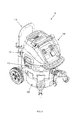
- a vacuum system 10 in accordance with an embodiment of the invention includes a body 100 having a tank portion 105 coupled to a head or lid portion 110 via one or more latch devices 112, as well as an optional handle assembly 115.
- the tank 105 may possess any dimensions and shapes suitable for its described purpose.
- the tank 105 is generally cylindrical. In another embodiment, it may possesses a generally frustoconical shape.
- the tank 105 includes a curved side wall 205, a closed lower end or bottom 207 and an open upper end or mouth 210.
- the interior surface of the tank bottom 207 may be generally concave, possessing a slightly upward curve to, e.g., prevent the tank from sagging when filled with a predetermined amount of debris.
- the tank mouth 210 defines a rim 212 configured to engage a corresponding shoulder forming the separator plate 900 ( FIG. 9A ) inserted into the tank.
- the tank rim 212 is may protrude radially outward from the side wall 205, thereby forming a lip 213 about the mouth 210 of the tank 105.
- the tank 105 defines an open cavity or collection chamber 214 operable to collect and store debris drawn therein.
- the tank 105 further includes a forward handle 215 extending radially from the exterior surface of the side wall 205 (e.g., from the tank lip 213), and a rearward bracket 217 extending radially from the exterior surface of the side wall 205 at a location that is generally diametrically opposed from the forward handle position 215 (e.g., the bracket is oriented approximately 180° from the handle).
- the bracket 217 which couples the handle assembly 115 to the tank portion 105, includes an elongated housing section 220, a first sleeve 222A disposed along one side of the housing section, and a second sleeve 222B disposed along the opposite side of the housing section.
- Each sleeve 222A, 222B is configured to receive an arm 405A, 405B ( FIG. 4A ) of the handle assembly 115.
- the bracket housing section 220 cooperates with the housing section 420 of the handle assembly 115 to define a housing for a handle lock mechanism, with the bracket housing section 220 forming the upper portion of the lock mechanism housing, and the handle assembly housing section 420 forming the lower portion of the lock mechanism housing.
- the bracket housing section 220 includes an opening 225 through which the actuator 430 ( FIG. 4D ) of the lock mechanism protrudes (discussed in greater detail below).
- the tank portion 105 further may further include one or more latch receptacles formed into the side wall 205.
- the side wall 205 includes a first latch receptacle 227A spaced (e.g., diametrically opposed) from a second latch receptacle 227B, each being disposed proximate tank rim 212.
- Each latch receptacle 227A, 227B is defined by a pair of opposed, spaced projections 230A, 230B located along the circumference of the tank 105.
- Each projection 230A, 230B extends downward (axially) from the tank mouth 210, along the exterior surface of the side wall 205.
- Each latch receptacle 227A, 227B receives a corresponding latch device 112 operable to couple the tank 105 to the separator plate 900 (discussed in greater detail below).
- the vacuum 10 further includes a transport assembly that enables movement of the vacuum over a surface.
- the vacuum 10 may include on or more wheel assemblies that couple to the tank 105.
- the tank 105 includes a plurality of notches or slots 235A, 235B, 235C, 235D angularly spaced about the tank bottom 207.
- Each notch 235A - 235D is recessed into the side wall 205, being contoured to receive a corresponding connector on a wheel assembly.
- the notch 235A - 235D defines a dove tail, having a narrow neck portion 240 and a widened base portion 245 contoured to mate with a similarly shaped pin on the wheel assembly (discussed in greater detail below).
- Each notch 235A - 235D further includes a female coupling member or socket 250 (e.g., a generally cylindrical socket) adapted to receive a corresponding male coupling member disposed on the wheel assembly connector.
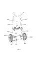
- the wheel assembly may be in the form of a caster 305 including a top plate or support 310 and a wheel 315 disposed along distal section of the support.
- the wheel 315 is rotatably mounted to a fork 320 that, in turn, is pivotally coupled to the support 310 via a central pin 322.
- the proximal section of the support 310 includes a connector 325 adapted to mate with one of the notches 235A - 235D formed into the tank 105.
- the connector 325 is a pin extending axially from the proximal end of the support 310.
- the pin is contoured, including a narrow neck portion 330 (corresponding with the neck portion 240 of the notch 235A - 235D) and a widened base or end portion 335 (corresponding with the base portion 245 of the notch).
- a male coupling member or post 340 e.g., a cylindrical post
- the tank socket 250 may further include threaded channel operable to engage a threaded fastener that passes through the post 340, securing the caster 305 within the notch 235A - 235D. Connection of the caster 305 to the tank 105 is best seen in FIG. 5 .
- the tank 105 further includes an intake port 255 formed into the side wall 205 (along the forward portion of the side wall).
- a vacuum connector 260 secured to the exterior side of the intake port 255, couples to a hose connector 265, which, in turn, couples to a flexible tube (e.g., a hose) utilized to capture debris.
- An exterior cap 270 tethered to the vacuum connector 260, may be utilized to seal the port.
- the intake port, vacuum connector, hose connector, flexible tube, and cap may possess any shape and dimensions suitable for its intended purpose.
- any of the intake port, vacuum connector, hose connector, flexible tube, and cap may be generally circular and/or cylindrical.
- An inlet device 600 ( FIG. 6A ) may be secured to the interior side of the intake port 255 (discussed in greater detail below).
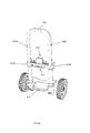
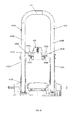
- the handle assembly 115 includes a base member 400, a first upright arm 405A extending upward from the base, a second upright arm 405B laterally spaced from the first upright arm 405B, and a gripping member 410 connecting the first arm to the second arm.
- the first 405A and second 405B arms, as well as the handle 410 may possess any shape and dimensions, and may be formed of any materials suitable for their described purpose.
- the handle arms 405A, 405B and the gripping member 410 may be generally tubular and/or cylindrical.
- the handle arms 405A, 405B and gripping member 410 may be formed of steel tubing. In other embodiments, plastic may completely form, or may form portions of, the handle assembly.
- Each handle arm 405A, 405B includes a lower or proximal portion 412A secured to the base member 400 and an upper or distal portion 412B telescopically coupled to the proximal arm portion such that the distal arm portion nests within the proximal arm portion.
- the height of the gripping member 410 may be adjusted with respect to the base member 400.
- the handle assembly 115 may reconfigured from a first, collapsed position (as shown in the figures) to a second, extended position (not illustrated).
- the gripping member 410 is secured at a desired vertical or telescopic position via an arm lock mechanism 415 that cooperates with a plurality of apertures longitudinally (vertically) spaced along the arms 405A, 405B.
- the distal portions 412B of the arms 405A, 405B may include a first set of arm apertures 417A disposed proximate the longitudinal center of the arm proximal portion 412B, as well as a second set of arm apertures 417B disposed proximate the lower end of the arm proximal portion 412B (seen best in FIG. 4B ).
- the handle assembly housing section 420 cooperates with the bracket housing section 220 to form a lock mechanism housing that houses the lock mechanism 415.
- the handle assembly housing section 420 includes a first sleeve 422A and a second sleeve 422B laterally spaced from the first sleeve.
- the first sleeve 422A of the handle assembly housing section 420 is configured to align with the first sleeve 222A of the bracket housing section 220.
- the second sleeve 422B of the handle assembly housing section 420 aligns with the second sleeve 222B of the bracket housing section 220.
- the handle assembly housing section 420 further includes a guide block 425 centrally disposed within the housing section.
- the guide block 425 is a generally planar element extending distally from the lower surface of the housing section interior.
- a post 427 extends distally (upward) from the distal end of the guide block 425.
- the post 427 couples to a biasing member 475 such as a spring that biases the actuator 430 in its normal position (discussed in greater detail below).
- the outer surface of the handle assembly housing section 420 may be contoured with features such as finger indentations to aid in the gripping of the housing during operation of the lock mechanism.
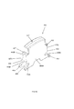
- the actuator 430 possesses a generally U-shaped configuration defined by an engagement portion 432 and a carriage portion 435.
- the transverse dimension of the engagement portion 432 may be less than the transverse dimension of the carriage portion 435. That is, the carriage portion 435 may be wider than the engagement portion 432 to form a shoulder or stop 437.
- the actuator 430 is trapped within the bracket housing section 220, and the extension of the actuator through the opening 225 is limited by contact between the shoulder 437 and the housing section 420. That is, only the engagement portion 432 extends through the opening 225 since the shoulder 437 serves as a stop, preventing the extension of the actuator from the opening 225 beyond the shoulder.
- the carriage portion 435 includes a first or forward wall 440A and a second or rearward wall 440B that cooperate to define a cavity 442 therebetween.
- the cavity 442 receives the guide block 425 to permit the axial repositioning of the actuator 430 along the guide block 425.
- the walls 440A, 440B of the carriage portion 435 each includes aligned, tapered (e.g., V-shaped) slots 445A, 445B disposed along each lateral side 447A, 447B of the carriage portion 435.
- the slots 445 are defined by an upper projection 450 protruding slightly from the lateral side 447A, 447B of the engagement portion 432, and a lower finger 452 extending angularly from the lateral side at a distance greater than that of the projection 450.
- the lock mechanism 415 further includes a first lever 455A and a second lever 455B operable to rotate within the lock mechanism housing.
- the levers 455A, 455B are generally L-shaped, including a hub 457, a first or horizontal arm 460, and a second or vertical arm 462 oriented generally orthogonal to the first arm.
- the hub 457 defines a central pivot point P about which each lever 455A, 455B pivots.
- the first arm 460 of each lever 455A, 455B is contoured to mate with the slots 445 of the actuator 430.
- the distal end of the first arm 460 may be enlarged such that spans the opening between forward 440A and rearward walls 440B, extending from the slot 445A formed into the forward wall 440A to the slot 445B formed into the rearward wall 440B.
- the movement of the actuator 430 i.e., the axial/vertical movement of the carriage portion 435 along the guide block 425) causes a corresponding rotation of each lever 455A, 455B about its pivot point P.
- the second arm 462 of the first 455A and second 455B levers are configured to drive locking pins that engage the arms of the handle assembly 115.
- the first lever 455A is in communication with a first locking pin 465A
- the second lever 455B is in communication with a second locking pin 465B.
- the first locking pin 465A extends from the first lateral side 447A of the actuator carriage portion 435 to the first arm 405A.
- the second locking pin 465B extends from the second lateral side 447B of the actuator carriage portion 435 to the second arm 405B.
- the distal (arm facing) portion of each pin 465A, 465B engages the arm apertures 417A, 417B formed into the arm 405A, 405B as discussed above.
- Each locking pin 465A, 465B is retractable, being configured to translate (move without rotation) along its longitudinal axis. Specifically, each locking pin 465A, 465B moves from a first, retracted position, in which it is drawn toward the actuator 430, to a second, extended position, in which the locking pin is driven outward from the actuator and the distal portion of the pin engages the aperture of 417A, 417B its associated arm 405A, 405B. As noted above, the second arm 460 of each lever 455A, 455B is in communication with the locking pins 465A, 465B. Specifically, each locking pin 465A, 465B includes a socket 470A, 470B disposed at an intermediate pin location.
- each second lever arm 462 is received within a socket 470A, 470B, linking the lever 455A, 455B to the locking pin 465A, 465B. Consequently, rotation of the lever 455A, 455B drives the movement of its associated locking 465A, 465B from the first pin position to the second pin position, and vice versa.
- the operation of the lock mechanism 415 is explained with reference to FIGS. 4F and 4G .
- the actuator 430 is spring biased in its normal (e.g. upward) position by a biasing member 475 (e.g., a spring).
- a biasing member 475 e.g., a spring
- the locking pins 465A, 465B are oriented in their extended position, in which the distal end of each pin extends through the aperture 417A, 417B formed into the arm distal portion 412B.
- movement of the distal arm portion 412B with respect to the proximal arm portion 412A is prevented, locking the handle 410 at a first vertical height.
- the actuator 430 is engaged by pressing the engagement portion 432 downward (indicated by arrow F) to overcome the biasing force of the biasing member 475.
- the carriage portion 435 is driven axially downward, sliding along the guide member 425.
- the first arms 460 captured within the carriage slots 445A, 445B, are driven downward, rotating the levers 455A, 455B about their pivot points P. From the viewpoint of FIGS. 4F and 4G , when the actuator 430 is urged downward, the first lever 455A rotates clockwise, while the second lever 455B rotates counterclockwise.
- This rotation further causes second arms 462 to rotate inward (toward the actuator 430), thereby driving the locking pins 465A, 465B inward, from the extended pin position to the retracted pin position (indicated by arrow T). That is, the distal portion of each locking pin 465A, 465B disengages the aperture 417A, 417B of its corresponding arm 405A, 405B. In the disengaged position, the distal arm portion 412B is free to telescope into and out of the proximal arm portion 412A, and the height of the handle 410 with respect to the base 400 (indicated by arrow M) may be adjusted.
- the distal arm portion 412B may telescope outward from a first arm position, in which the locking pins 465A, 465B are aligned with the first arm apertures 417A, to a second arm position, in which the locking pins are aligned with the second arm apertures 417B.
- Releasing the engagement portion 432 permits the biasing member 475 to return the actuator 430 to its normal position, driving the carriage portion 435 upward and rotating the levers 455A, 455B in an opposite direction.
- This rotation of the levers 455A, 455B moves the locking pins 465A, 465B from the retracted pin position to the extended pin position, driving the locking pins outward locking the handle 410 at a second vertical height.
- the base member 400 may further include wheels 480A, 480B (e.g., dolly wheels mounted on a common axle) and connectors 485A, 485B adapted to mate with notches 235C, 235D formed into the tank 105, as shown in FIG. 5 .
- wheels 480A, 480B e.g., dolly wheels mounted on a common axle
- connectors 485A, 485B adapted to mate with notches 235C, 235D formed into the tank 105, as shown in FIG. 5 .
- the tank 105 further includes an inlet device adapted to direct the flow of air and debris entering the collection chamber.
- the inlet device 600 includes a stem portion 605 coupled to the intake port 255 and a baffle portion 610 including a closed distal end 615 with a curved fin 620 and a window 625 formed into the side wall of the baffle.
- the stem portion 605 may be generally cylindrical, extending radially inward from the side wall 205 inner surface.
- the baffle portion 610 is configured to deflect incoming air and debris as it travels through the conduit.
- the baffle 610 via the fin 620, alters the travel path of contaminated fluid (air/water with debris) approximately 90° such that the fluid is directed radially outward, toward the side wall 205 of the tank 105.
- the inlet device 600 further includes an electrostatic charge system operable to connect the inlet device to the ground of the main power supply.
- Contaminated fluid e.g., debris-laden air
- the vacuum system 10 may further include an electrostatic discharge device that connects the electrical ground of the vacuum to the hose system.
- the electrostatic discharge device includes a support or extension 630 coupled to a conductive member 635 (e.g., a flat copper spring) having a proximal portion 645 and a distal portion 650.
- a first metal fastener 640 connects the conductive member 635 to the support 630.
- a second metal fastener 655 connects the distal portion 650 of the conductive member 635 to the separator plate 900, with the conductive member being disposed within a protrusion 990 extending downward from the separator plate ( FIG. 9C ).
- the inlet device 600 may be formed of an electrically conductive material (e.g., electrically conductive plastic). With this configuration, the static discharge system creates an electrically conductive path that allows static charge from the hose, the hose connector, etc., to travel through the intake device, along the extension, up through the conductive member and to the main electrical ground.
- the interior of the tank 105 may further be keyed such that the separator plate 900 (discussed below) couples to the tank in a single rotational orientation.
- the interior surface 670 of the tank side wall 205 includes a first guide rib or element 675A and a second guide rib or element 675B.
- the guide elements 675A, 675B which extend radially inward from the side wall interior surface 670, are disposed at predetermined angular positions along the side wall 205 such that the guide elements align with slots formed into the forward legs 907A, 970B of the separator plate 900 ( FIG. 9C ).
- the separator plate 900 may be inserted into the tank cavity in a predetermined orientation, with platform of the being disposed in a particular rotational position with respect to the collection chamber (i.e., one in which the slot formed into each of the two forward legs of the separator plate align with a corresponding guide element 675A, 675B, discussed in greater detail below).
- the vacuum head 110 includes a shell 705 including axial connection posts 707 disposed at predetermined locations along head interior surface. Each head post 707 aligns with a corresponding post 917 disposed on the separator plate 900 ( FIG. 9A ).
- the distal end of plate post 917 may include a receptacle that receives the distal end of the head post 707.
- a fastener may pass through the posts 707, 917 to secure the vacuum head 110 to the separator plate 900.
- the vacuum head 110 further includes a pair of opposed handle openings or cut-outs 710A, 710B formed into the shell 705.
- Each handle cut-out 710A, 710B defined by a downward-extending wall 712, defines a cavity within the vacuum head 110 that receives the hook portion of the latch device 112, as well as exposes a portion of the separator plate such that it may be engaged by the hook portion (explained in greater detail below).
- each cut-out 710A, 710B When coupled to the tank, each cut-out 710A, 710B generally aligns with an associated latch receptacle 227A, 227B.
- the vacuum head 110 may further include one or more vents disposed at predetermined locations along the shell.
- the vacuum head 110 includes a first or vacuum discharge vent 715A (aligned with the vacuum exhaust), a second or motor intake vent 715B (aligned with the motor air intake), and a third or motor discharge vent 715C (aligned with the motor exhaust).
- Each vent 715A, 715B, 715C is in fluid communication with a corresponding system to permit the flow of air into and/or out of the vacuum head 110.
- Each vent 710A - 710C includes an open chute 716 formed into the shell 705 that receives a corresponding louver assembly 717.
- each louver assembly 717 may slide axially into and out of the open chute 716.
- the louvers 717 may be configured to direct air any desired direction.
- the head 110 further houses the electrical and electronic components of the vacuum system 10; consequently, it includes a control panel or dashboard 720 and one or more actuators 725 (e.g., a control knob) operable to control the operational parameters of the device, including, but not limited to, power (ON/OFF) and the fan speed of the motor.
- the dashboard may further include an outlet 727 to which a power cord may be connected.
- the electrical components may be controlled via a circuit board 729 mounted to the interior surface of the dashboard 720.
- the head 110 further includes a handle or gripping member 730 to aid in separation of the head 110 from the tank portion 105.
- the first lateral side 735A of the handle 730 includes a first lateral extension 740A.
- the second lateral side 735B of the handle 730 includes a second lateral extension 740B.
- Each lateral extension 740A, 740B may be generally arcuate, curving downward along its outer end.
- the handle 730 provides a coupling area that enables the wrapping of a cord around the handle (e.g., the electrical cord of the vacuum system 10).
- a latch device 112 couples the separator plate 900 to the tank 105.
- a latch device 112 includes a gripping member or body 805 and a locking mechanism 810 coupled to the inner (tank facing) side of the gripping member.
- the latch body 805 includes a lower handle portion 815 and an upper hook portion 820 configured to engage a lip disposed on the separator plate 900.
- the exterior side of the gripping member 805 further includes an extension 825 extending angularly outward from the upper end of the handle portion 815.
- the locking mechanism 810 may be any conventional lock mechanism suitable for its described purpose.
- the locking mechanism 810 may include a pivot member 830 pivotally coupled via a lower pin 835A to the handle portion 815 (by way of handle apertures 837) and pivotally coupled to a bracket 840 via an upper pin 835B (by way of bracket apertures 842).
- the bracket 840 is coupled to the tank 105 via plate member 845.
- the bracket 840 and the plate member 845 include connection holes 847 that receive fasteners such as bolts.
- the pivot member 830 is biased via a biasing member 850 (e.g., a spring) configured to draw the hook portion 820 downward when the gripping member 805 is positioned in its normal, locked position.
- a biasing member 850 e.g., a spring
- the latch device 112 begins in its normal, locked position, in which hook portion 820 is positioned within a handle cut out 710A, 710B such that the hook portion 820 engages the lip 920A, 920B of the separator plate 900 ( FIG. 9A ).
- the handle portion 215, moreover, is positioned within a latch receptacle 227A, 227B.
- the separator plate is drawn downward by the hook portion 820, being held into engagement with the tank rim 212.
- the lower end of the handle portion 815 is pivoted outward (away from the tank 105, indicated by arrow Z) to overcome the biasing force of spring 850 in the locking mechanism 810.
- the gripping member 805 is moved from its normal, locked position to its unlocked position (not illustrated).
- the hook portion 820 is no longer held taut against lip 920A, 920B on the separator plate 900.
- the hook portion 820 may be manipulated further by grasping the extension 825 maneuvering it to completely disengage the hook portion 820 from the lip 920A, 920B and/or repositioning the gripping member 805 such that it clears the handle cut-outs 710A, 710B formed into the lid 100.
- the reverse process is followed, with the hook portion 820 being positioned on the lip, e.g., via manipulation of the extension 825, and the handle portion 815 being rotated inward (toward the tank) to draw the hook portion 820 downward into tight contact with the lip 920A, 920B.
- a separator plate 900 engages the tank rim 212, separating the tank cavity 214 (the collection chamber) from the cavity of the vacuum head 110 (also called a motor chamber).
- the separator plate 900 includes a platform 905 (e.g., a generally circulate plate) and one or more leg members 907A-907D.
- the platform 905 includes an upper (head facing) surface 910 and a lower (tank facing) surface 912.
- the shaped and dimensions of the platform 905 may be any suitable for its described purpose.
- the platform 905 may be substantially planar and possess a generally circular shape.
- the upper surface 910 of the platform 905 may further include one or more connection posts 917 that engage (e.g., mate, receive, etc.) corresponding connection posts 707 extending from the vacuum head 110. Fasteners may extend through the connection posts 707, 917 to secure the lid 110 to the separator plate 900.
- a pair of diametrically opposed lips 920A, 920B extends axially (upward) from the perimetral wall 915 to provide an engagement member for each of the latch devices 112, as described above.
- the platform 905 may further include one or more reinforcing ribs 921 spanning the platform upper surface 910 to enhance the strength of the platform.
- the leg members 907A - 907D extending distally from the platform lower surface 912, are configured to elevate the platform 905 and, in particular, to suspend the filter system above a supporting surface when the separator is placed directly upon the supporting surface. That is the length of the legs is selected to prevent the filters from contacting the ground when the separator plate 900 and/or head 110 is removed from the tank and set on a surface (seen in FIGS. 7E and 15A ).
- the leg members 907A - 907D are located proximate the outer edge of the separator plate, being disposed a predetermined angular positions thereon.
- the leg members 907A - 907D are configured to key the separator plate 900 to the tank 105 such that the separator plate is oriented in a specific rotational position when inserted into the tank 105.
- the platform 905 includes a first forward leg 907A, a second forward leg 907B, a first rearward leg 907C, and a second rearward leg 907D.
- Each leg 907A - 907D includes a proximal leg portion 922 and a distal leg portion 925.
- the proximal leg portion 922 of the forward legs 907A, 907B includes a notch 927 (e.g., a tapered (V-shaped) notch) configured to receive the guide element 675A, 675B protruding from the interior surface 670 of the tank 105.
- a notch 927 e.g., a tapered (V-shaped) notch
- the guide element 675A, 675B is positioned at predetermined positions along the tank.
- the notch 927 aligns with each of the tank guide elements 675A. 675B such that the first guide element 675A is received within the notch of the first forward leg 907A and the second guide element 675B is received within the notch of the second forward leg 907B.
- the notch 927A of first leg member 907A must be aligned with the first guide element 675A and the notch 927B of the second leg member 907B must be aligned with the second guide element 675B.
- the forward (notched) leg members 907A, 907B not be aligned with their corresponding guide elements 675A, 675B (i.e., should the rotational position of the separator plate 900 differ from the normal/predetermined position such that no leg or an unnotched leg is aligned with the guide elements), insertion of the separator plate 900 into the tank cavity 214 will be prohibited.
- the separator plate 900 further includes a conduit system to enable the flow of air between the tank 105 (the collection chamber 214) and the head 110 (the motor chamber).
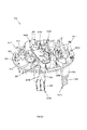
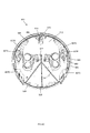
- the platform 905 of the separator plate 900 includes a central, raised platform or deck 902 with a first conduit pair 935 and a second conduit pair 940.
- the first conduit pair 935 includes a first (forward) suction conduit or port 935A and a first (rearward) cleaning conduit or port 935B.
- the second conduit pair 940 includes a second (forward) suction conduit or port 940A and a second (rearward) cleaning conduit or port 940B.
- the conduits 935A, 935B of the first conduit pair 935 are positioned such that the conduits are disposed over the first filter 1505A ( FIG.15 ) of the filter system, while the conduits 940A, 940B of the second conduit pair 940 are positioned such that they are disposed over the second filter 1505B of the filter system (i.e., each filter is in fluid communication with a conduit pair).
- each conduit 935A, 935B, 940A, 940B may possess any shape and dimensions suitable for their described purpose.
- each conduit 935A, 935B, 940A, 940B may be generally cylindrical.
- Each conduit moreover, may include a conduit baffle operable to direct the airflow in a predetermined direction.
- the suction conduit 935A, 940A may include an inboard conduit baffle 942A that curves radially inward with respect to the platform 905 to direct the air inboard, while the cleaning conduits 935B, 940B may include an outboard conduit baffle 942B that curves radially outward to direct air outboard (toward the perimeter of the platform).
- the upper surface 910 of the platform 905 further includes first 945A, second 945B, and third 945C support walls that cooperate to support the airflow assembly.
- the first support wall 945A extends upward from the upper surface 910 of the platform 905, being oriented between the suction 935A, 940A and the cleaning 935B, 940B conduits.
- the second support wall 945B is disposed proximate the cleaning conduits 940A, 940B (i.e., is disposed outboard with respect to the first support wall).
- the third support wall 945C moreover, is positioned outboard from the second support wall 945B.
- Each support walls 945A - 945C is spaced from its adjacent support wall to define a cavity therebetween.
- first 945A and second 945B support walls define a fan cavity 950 that receives the fan of the airflow assembly.
- the second 945B and third 945C support walls cooperate to define a motor cavity 955 that receives the motor of the airflow assembly.
- Each support wall 945A, 945B, 945C includes a cut-out section 947 that receives and supports various components of the airflow assembly.
- the second and third support walls cooperate to support the motor of the airflow assembly, with the motor resting within the cut-out section.
- the motor cavity 955 further includes areas 957 for supporting valve solenoid switches (discussed in greater detail below).
- the separator plate 900 further includes a pair of opposed motor intake walls 958 extending from the third support wall 945C to the perimetral wall 915.
- the motor intake walls 958 cooperate with a motor shroud 1205 ( FIG. 12A ) to define a motor air intake area 960 that aligns with second head vent 715B.
- opposed walls 962 cooperate with the motor shroud 1205 to define a motor exhaust area 965 that aligns with third head vent 715C.
- a deflection wall or baffle 970 extends upward from platform upper surface 910 (e.g., the height of the wall may be substantially equal to or greater than the height of the deck 902).
- the platform baffle 970 is positioned between the deck 902 and the perimetral wall 915.
- the platform baffle 970 gradually curves such that it extends from a position along a lateral side of the deck 902 to a position along the forward side of the deck.
- the platform baffle 970 is operable to direct cooling air exhausted by the manifold 1305 ( FIG. 13A ) toward electronics housed within the head 110, thereby cooling the electronics (discussed in greater detail below).
- the platform 905 further includes a first yoke 975A located proximate the first cleaning conduit 935B and a second yoke 975B located proximate the second cleaning conduit 940B.
- Each yoke 975A, 975B supports an associated butterfly valve 1005A, 1005B ( FIG. 10A ) of the valve assembly to enable rotation of the valve on the yoke (discussed in greater detail below).
- the platform lower surface 912 is best seen in FIG. 9C .
- platform lower surface 912 includes a recessed area 977 generally corresponding with the raised deck 902 of the platform upper surface 910.
- the perimetral wall 915 of the platform upper surface 910 moreover, defines a shoulder 980 on the platform lower surface 912.
- An axial wall 982 extends downward from the lower surface shoulder 980, being disposed slightly inboard from the circumference of the separator plate 900.
- the axial wall 982 ( FIG. 8C ) is wrapped with a generally U-shaped sealing member or gasket 983 configured to contact the rim 212 of the tank 105 and thereby fluidly seal the joint between the tank rim 212 and the shoulder 980.
- a series of downward-extending, angled fins 985 may be angularly spaced about the platform 905, being located near the outer edge of the platform, proximate the shoulder 980.
- the fins 985 serve as guides during the insertion of the separator plate 900 into the tank cavity 214.
- a bracket 990 is also disposed on the platform lower surface 912 that receives the conductive member 635 of the electrostatic discharge device. As shown, the conductive member 635 is coupled to the platform 905 via the conductive fastener 655.
- a valve assembly disposed on platform upper surface 910, opens and closes one or more of the separator conduits 935A, 935B, 940A, 940B to selectively permit fluid (air) therethrough.
- the valve assembly 1000 includes a first solenoid 1002A in communication with to a first butterfly valve 1005A and a second solenoid 1002B in communication with to a second butterfly valve 1005B.
- the first butterfly valve 1005A is supported by the first platform yoke 975A, while the second butterfly valve is supported by the second platform yoke 975B.
- valve assembly 1000 is positioned on the separator plate 900, with each solenoid 1002A, 1002B being positioned within areas 957 as described above.
- the solenoids 1002A, 1002B may be secured to the platform 905 by a cover or bridge 1040 coupled thereto.
- the first butterfly valve 1005A selectively permits airflow through the first conduit pair 935A, 935B.
- the second butterfly valve 1005B selectively permits airflow through the second conduit pair 940A, 940B.
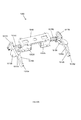
- Each butterfly valve 1005A, 1005B includes an elongated shaft 1010A, 1010B supporting a first or distal disc 1015A and a second or proximal disc 1015B longitudinally spaced along the shaft and rotationally offset from the distal disc by, e.g., approximately 45°.
- the proximal end of the shaft 1010A, 1010B is connected to a crank arm 1017A, 1017B, which, in turn, is pivotally coupled to a linking member 1020A, 1020B via a pivot pin 1022A, 1022B.
- the linking member 1020A, 1020B is repositioned via a plunger 1025A, 1025B that is driven by the solenoid 1002A, 1002B. Specifically, the plunger 1025A, 1025B reciprocates axially to rotate the discs.
- the linking member 1020A, 1020B may further include a downward-extending, curved support or ski 1030A, 1030B configured to slide along the platform upper surface 910 as the plunger 1025A, 1025B reciprocates.
- each solenoid 1002A, 1002B may be selectively engaged to rotate the shaft 1010A, 1010B about its longitudinal axis in a clockwise or counter clockwise direction.
- the degree of rotation includes, but is not limited to, approximately 45°.
- the valve assembly 1000 may selectively position each disc 1015A, 1015B with respect to its associated conduit 935A, 935B, 940A, 940B to enable the passage of fluid (e.g., air) therethrough.
- the valve assembly 1000 rotationally positions the discs 1015A, 1015B in a first position, in which the suction conduits 935A, 940A are opened and the cleaning conduits 935B, 940B are closed. That is, the butterfly valve 1005A, 1005B positions the shaft 1010A, 1010B such that the first disc 1015A is oriented generally transverse to the opening defined by the suction conduit 935A, 940A (as illustrated in FIG.
- the valves 1005A, 1005B may rotationally position the discs 1015A, 1015B in a second (reversed) position, in which the suction conduits 935A, 940A are closed and the cleaning conduits 935B, 940B are opened.
- the conduits 935A, 935B, 940A, 940B and discs 1015A, 1015B are configured such that air flowing through the conduit creates a balanced system in which the forces on the butterfly valve 1005A, 1005B are equally applied across both surfaces of the disc 1015A, 1015B (indicated by arrows F1 and F2).
- the downward force (F1 upper) on one side of the rotating axis is generally equal to the downward force (F2 upper) on the other side of the axis. Therefore, a pressure on the top side of the disk does not significantly increase the force necessary to toggle the valve.
- the conduit structure enables the use of a lower power solenoid since valve rotation does not require overcoming a significant eccentric force applied to the disc 1015A, 1015B by the air in or airflow through the conduit.
- the airflow assembly housed within the motor chamber defined by head 110 and supported on the upper platform surface 910, generates air pressure (positive and/or negative), within the vacuum device 10, as well directs the flow of air within the head 110.
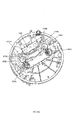
- the airflow assembly includes an airflow generating device 1102 having a centrifugal fan 1105 driven by a motor 1107.
- the fan 1105 includes an annular housing or baffle 1110 and a plurality of slots 1112 disposed about the perimeter of the housing.
- the slots 1112 may be angled (e.g., offset and/or nonparallel to the rotational axis of the housing) to direct air in a predetermined direction.
- the airflow generating device 1102 may further include a forward gasket 1122 coupled to the forward (inboard facing) side of the fan 1105, and a manifold spacer 1125 coupled to the rearward side of the fan.
- the motor 1107 may include any type of motor suitable for its described purpose.
- the motor 1107 may include a universal series motor with a central channel 1127.
- the motor 1107 is configured to drive (e.g., rotate) the fan 1105 in a clockwise and/or counterclockwise direction, as well as to draw cooling air into the motor channel 1127.
- the motor 1107 rotates the fan 1105 in a predetermined direction to generate a negative pressure within the vacuum device 10, which, in turn, generates a suction airstream (an intake airstream) that enters the tank portion 105 via the inlet port 255.
- the forward side of the motor 1107 may be coupled to the rearward (outboard facing) side of the fan 1105, and a rearward gasket 1130 may be coupled to the outboard side of the motor.
- the airflow generating device 1102 is oriented on the separator plate platform 905 such that it is located between the butterfly valves 1005A, 1005B, with the fan 1105 and manifold spacer 1125 being positioned within the fan cavity 950 of the platform 905, as well as aligned with the cut out section 947 formed into the first 945A and second 945B walls.
- the motor 1107 moreover, is position within motor cavity 955 such that the motor channel 1127 is aligned with the cut-out sections formed into the second 945B and third 945C platform walls.
- the fan 1105 is oriented such that its rotational axis R is oriented generally horizontally, i.e., such that the rotational axis is generally parallel to the platform 905 of the separator plate 900.
- the fan rotational axis R is oriented generally transverse (e.g. orthogonal) to the longitudinal axis of a filter 1505A, 1505B ( FIG. 15 ).
- the air intake direction of the fan 1105 may be oriented generally transverse (e.g., generally orthogonal) to the airflow passing through the conduit pairs 935, 940.
- the motor 1107 is housed in a motor shroud 1205 defining a motor air intake port 1210 and a motor air outlet or exhaust port 1220.
- the motor shroud 1205 separates the cooling airstream generated by the motor from the vacuum airstream.
- the intake port 1210 cooperates with walls 958 on the platform 905 to define the motor intake area 960 as described above.
- the exhaust port 1220 cooperates with the walls 962 on the platform upper surface 910 to define the motor exhaust area 965 as described above.
- the ambient air is drawn into the motor air intake 1210, travels over the motor (cooling it), and is then exhausted via motor air exhaust 1220.
- the airflow assembly further includes a manifold operable to direct the airflow in predetermined directions.
- the manifold includes a plurality of chambers that function as baffles, cooperating to direct airflow in predetermined directions.
- the manifold 1305 includes a forward inlet chamber 1310, an intermediate fan discharge chamber 1315, and a rearward exhaust chamber 1320.
- the exhaust chamber 1320 includes an exhaust port 1325 to permit exhaust of the filtered air from the manifold 1305.
- the fan discharge chamber 1315 includes a first window or opening 1330 configured to permit the flow of fluid between the fan discharge chamber 1315 and the exhaust chamber 1320.
- the fan discharge chamber 1315 includes a second window or opening 1335 including an interior deflector 1337 extending angularly inward into the fan discharge chamber such that directs a portion of the air flowing downstream, through the manifold out of the manifold and into the cavity defined by the head 110.
- the inlet chamber 1310 is positioned over the suction conduits 935A, 940A, the discharge chamber 1315 is positioned over the fan 1105 and the cleaning conduits 935B, 940B, and the exhaust chamber 1320 is positioned over the motor shroud 1205.
- the operation of the manifold 1305 is discussed in greater detail below.
- the vacuum device 10 includes a filter assembly that captures particles within the contaminated airstream entering the tank 105, cleaning the airstream as the airstream flows through the body 100 of the vacuum device 10.
- the filter assembly 1500 includes a first filter 1505A and a second filter 1505B.
- the filters 1505A, 1505B may be coupled to the platform lower surface 912, being generally radially aligned along opposite sides of plate center point and suspended above the floor of the tank 105. Additionally, as best seen in FIG.
- each filter 1505A, 1505B is in communication with both conduits 935A, 935B, 940A, 940B forming a conduit pair 935, 940 (i.e., the first filter 1505A is in fluid communication with the first conduit pair 935, while second filter 1505B is in fluid communication with second conduit pair 940).
- each filter 1505A, 1505B may include a substantially rigid, inner cage 1605 generally concentrically disposed within a core member or outer cage 1610.
- the inner cage 1605 which houses a ball float 1612, may be generally cylindrical.
- the outer cage 1610 which formed of wire screen, may possess a generally frustoconical shape.
- the outer cage is generally rigid, providing stiffness from end to end such that it can be threadingly tightened along one of the ends to an end cap. Specifically, the lower (narrower) terminus of the outer cage 1610 couples to a lower end cap 1615, while the upper (wider) terminus of the outer cage couples to an upper end cap 1620.
- the lower end cap 1615 may be in form of a solid, circular plate with an exterior wall extending upward from the plate and extending about its periphery, as well as an inner wall or rib 1622 concentric with the outer wall and configured to engage the core member 1610 lower end.
- the upper end cap 1620 may be generally annular, including a plurality of ratchet teeth 1625 disposed along on its upper side (being angularly spaced about the perimeter of the cap).
- the inner channel 1630 of the upper end cap 1620 moreover, is threaded to mate with corresponding threads on a filter mount 1635 (discussed in greater detail below).
- a filter medium 1640 operable to remove particulates from the airstream is mounted on the outer cage 1610.
- the filter medium 1640 may in the form of a sleeve including a hollow channel 1642 defined by the interior surface of a wall 1643 and a plurality of longitudinal fins 1644 angularly spaced about the exterior surface of the wall.
- the filter medium 1640 may possess a shape and dimensions that enable it to contour to the exterior surface of the outer cage 1610 (e.g., the filter may be generally frustoconical).
- the filter medium 1640 may possess an upper (wide end) diameter of approximately 6.4 inches, a lower (narrow end diameter) of approximately 5.25 inches, and a length (height) of approximately 5.2 inches. It should be understood that the filter medium 1640 may possess any suitable shape and dimensions, and may be formed of any material an have any structure suitable for its described purpose.
- the filter mount 1635 secured to the lower surface 912 of the separator plate 900 (e.g., via fasteners), couples to the upper end cap 1620.
- the filter mount 1635 includes a seat member 1655 (e.g., a ball seat), a base 1660, and a threaded plug 1665 that engages the threads of the inner channel 1630 of the upper end cap 1620.
- a channel 1670 is formed into the filter mount 1635 to permit airflow from the filter to its associated conduit pair 935, 940.
- the operation of the vacuum device 10 is explained with references to FIGS. 17A - 17C and FIGS. 18A - 18C.
- the motor 1107 is activated (e.g., via controls 725 on dashboard 720), rotating the fan 1105.
- the fan 1105 creates a vacuum (suction) airflow within the body 100 of the vacuum device 10.
- the butterfly values 1005A, 1005B are positioned in their normal, full suction position. In this position, the vacuum device 10 generates suction airflow that is filtered through the filter medium 1640 of each filter 1505A, 1505B.
- the butterfly valves 1005A, 1005B are set such that both the first suction conduit 935A and the second suction conduit 940A are opened, and both the first cleaning conduit 935B and the second cleaning conduit 940B are closed.
- the fan 1105 draws contaminated air A1 including debris (particulate material) into the tank 105 (e.g., via an inlet/hose).
- the contaminated air A1 travels through the collection chamber 214 and is drawn toward the filters 1505A, 1505B.
- the air passes through the filter medium 1640 in a first filter direction, with the air entering the filter medium via the medium exterior surface.
- the filtered air A2 passes through the suction conduit 935A, 940A, i.e., from the collection chamber defined by the tank 105 and into the motor chamber defined by the vacuum head 110. Specifically, the filtered air A2 enters the manifold 1305 of the air assembly disposed within the motor chamber, entering the inlet chamber 1310. The filtered air A2 is drawn into the fan central aperture 1115 and is directed radially outward therefrom as fan exhaust or discharge air A3 (indicated by arrows). The discharge air A3 is directed, via the slots 1112, into the manifold discharge chamber 1315.
- the cleaner conduits 935B, 940B are closed/sealed; consequently, a portion of the discharge air A3 is directed from the discharge chamber 1315, through the first window 1330, and into the exhaust chamber 1320. Additionally, a portion of the discharge air A3 is deflected by manifold deflector 1337 such that it passes through the second window 1335. As such, a portion of the discharge air A3 exits the manifold 1305 (and the vacuum system 10) as manifold exhaust air A4 via manifold exhaust outlet 1325. Additionally, a portion of the discharge air is recycled as electronics coolant A3', exiting the manifold 1305 and returning to the motor chamber defined by the head 110 to cool electronics housed in the head (discussed in greater detail below).
- the filter medium 1640 of the first filter 1505A is purged of debris.
- the first butterfly valve 1005A is engaged to reorient the valve from its normal position to its purge position. Specifically, the first rod 1010A is rotated such that distal disc 1015A covers/seals the first suction conduit 935A and the proximal disc 1015B is positioned such that it is oriented generally transverse to the opening of the first cleaning conduit 935B. In this configuration, the first cleaning conduit 935B is opened, while the first suction conduit 935A is closed/sealed.
- the second butterfly valve 1005B remains in its normal position as described above, with the second suction conduit 940A being opened and the second cleaning conduit 940B being closed/sealed.
- the suction airflow through the first filter 1505A ceases. That is, contaminated air A1 no longer passes through the filter medium 1640 of the first filter 1505A via the filter medium exterior surface. Suction airflow through the second filter 1505B, however, is maintained.
- the filtered air A2 from the second filter 1505B enters the manifold 1305, where it is drawn into the fan 1105 and expelled through fan slots 1112 as discharge air A3.
- the discharge air A3 enters the central channel of the first filter 1505A (as defined by the inner cage 1605) and is forced radially outward, passing through the filter medium 1640 in a second filter direction. As shown in FIG. 18B , this outward airflow functions as a purging airflow effective to dislodge at least a portion of the debris and/or particles 1800 previously attached to and/or embedded within the filter medium 1640. Any remaining discharge air A3 (i.e., and discharge air not directed into the cleaning conduit 935B) is directed as indicated above, being expelled from the tank as either manifold exhaust A4 or being recycled as electronics coolant A3'.
- the filter medium 1640 of the second filter 1505B is purged.
- the same operation described above with regard to the first filter 1505A occurs with the second filter 1505B.
- the first butterfly valve 1005A is returned to its normal position, in which the first suction conduit 935A is opened and first cleaning conduit 935B is sealed/closed.
- the second butterfly valve 1005B is engaged, moving the valve from its normal position to a purge position, in which the second suction conduit 940A is closed and the second cleaning conduit 940B is opened.
- discharge airflow A3 drawn into the manifold 1305 as filtered air is either directed into the second cleaning conduit 940B, out of the head 1010 via the manifold exhaust chamber 1320, or back into the head 1010 via second window 1035.
- the discharge air A3 that is directed through the cleaning conduit passes through the filter medium 1640 of the second filter 1505B in a second direction (opposite the first direction), thereby purging the filter medium of debris captured thereon.
- the amount of time for the purge is not particularly limited.
- the airflow system may operate in the suction mode for a first predetermined period of time and in the purging/cleaning mode for a second predetermined period of time, with the second period of time being less than the first period.
- the valve system cycles, generating suction air for approximately 30 seconds, and then generating purge air for approximately 0.3 seconds, alternately purging the first filter 1505A and the second filter 705B. This process continues, with the filters 1505A, 1505B alternately being purged in approximately every 20 seconds.
- cooling air A5 for the motor 1007 is drawn in through the motor intake port 1210 of the motor shroud 1205, where it is directed across the motor, cooling it, and then out through motor exhaust 1220 as motor exhaust air A5'.
- the motor airflow A5, A5' remains separate from the vacuum airflow A1, A2, A3, A3', A4 vacuum filtered air, with the motor shroud preventing the motor air A5, A5' from entering the manifold 1305.
- FIG. 20 illustrates an electrical schematic for the vacuum device 10 in accordance with an embodiment of the invention.
- the electrical system 2000 includes a microprocessor 2005 in communication with the motor via motor connect 2010, as well as the butterfly valves 1005, 1005B via a solenoid connect 2015, which, in turn, is in communication with solenoid switches 1002A, 1002B.
- the system 2000 may further include a pressure or flow sensor 2020 operable to indicate when the intake airflow A1 is reaches (e.g., is above or below) a predetermined threshold value. By way of example, it may indicate when the airflow pressure or flow velocity is below a specified value, thereby notifying the user that the filters must be removed for manual cleaning or replacement.
Landscapes
- Engineering & Computer Science (AREA)
- Mechanical Engineering (AREA)
- Filters For Electric Vacuum Cleaners (AREA)
Abstract
The present invention is directed to a vacuum (10) including a dust extraction system. The system includes a filter assembly (1500), an airflow generation assembly (1002), and valve assembly (1000). The airflow generation assembly (1002) is configured to draw contaminated air toward the filter assembly (1500) and exhaust filtered air as a discharge stream. The filter assembly (1500) is configured to remove contaminants from the contaminated airflow by capturing particulate material suspended within the airflow. The valve assembly (1000) is configured to selectively direct filtered airflow into the filter assembly (1500) such that the filtered air stream cleans the filter (1505A, 1505B).

Description
- The present invention is directed toward a construction site or tool shop vacuum and, in particular, to a vacuum including a filter system and an airflow arrangement that periodically cleans the filter system during operation.
- Tool shop vacuum cleaners (e.g., wet-dry vacuums) are designed to collect debris from a work area or connected tool via suction. Such vacuums typically include a tank and motor that drives an impeller to generate an airstream within the tank. Since the airstream includes debris, care must be taken to prevent the debris from reaching the motor and causing damage. In light of this, conventional systems further include a filter positioned upstream from the motor to capture debris as the contaminated airflow passes through the tank. Over time, however, the debris accumulates on the filter, restricting airflow and hampering performance. For example, a filter initially enabling airflow of approximately 80 cfm may begin degrading within minutes of operation, diminishing airflow capacity to approximately 10 cfm. Consequently, conventional vacuum systems require regular cleaning or replacement of the filter. This process requires a user to stop vacuum operation, open the tank, and remove the filter for cleaning or replacement. This is a time-intensive process that interrupts workflow.
- Thus, it would be desirable to provide an airflow arrangement configured to clean a filter during operation, thereby increasing filter life and extending time between manual cleaning of the filter, as well as filter replacement.
- The present invention is directed toward a construction site shop vacuum including a tank and a lid coupled to the tank. A separator plate is disposed within the vacuum such that the lid generally defines a motor chamber and the tank generally defines a collection chamber. The motor chamber houses a motor assembly, which is supported by the separator plate. The collection chamber, oriented upstream from the motor assembly, houses a filter system suspended from the separator plate. The separator plate includes conduits that permit airflow between the collection and motor chambers. Airflow between the chambers is controlled utilizing a valve assembly that selectively opens and closes the conduits.
- Specifically, the valve assembly operates in a first mode, in which contaminated airflow is drawn into the collection chamber, passing through the filter system in a first direction. The filter medium of the filter system captures debris present in the airflow, cleaning the air passing therethrough. The filtered airflow is then directed into the motor chamber, exiting the vacuum as exhaust.
- The valve assembly further operates in a second mode, in which at least a portion of the filtered airflow is redirected from the motor chamber back into the collection chamber. Specifically, the airflow is directed through the filter system in a second direction to expel debris that has accumulated on the filter medium. With this configuration, the media of the filter system are periodically cleaned during operation of the vacuum.
-
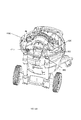
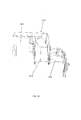
FIG. 1A illustrates a front perspective view of a vacuum in accordance with an embodiment of the invention. -
FIG. 1B illustrates a rear perspective view of the vacuum device shown inFIG. 1A . -
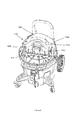
FIG. 2A illustrates a front perspective view of the tank of the vacuum device, shown in isolation. -
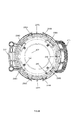
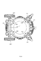
FIG. 2B illustrates a bottom plan view of the tank shown inFIG. 2A . -
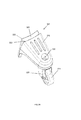
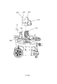
FIG. 3A illustrates a front perspective view of a wheel assembly in accordance with an embodiment of the invention, shown in isolation. -
FIG. 3B illustrates a rear perspective view of the wheel assembly shown inFIG. 3A . -
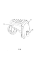
FIG. 4A illustrates a front perspective view of a handle assembly in accordance with an embodiment of the invention, shown in isolation. -
FIG. 4B illustrates a rear perspective view of the handle assembly shown inFIG. 4A . -
FIG. 4C illustrates a handle lock mechanism of the handle assembly, showing selected components disposed within a housing. A portion of which is remove for clarity. -
FIG. 4D illustrates an isolated view of the actuator of the handle assembly lock mechanism in accordance with an embodiment of the invention. -
FIG. 4E illustrates a rear, cross-sectional view of the handle assembly, with the wheels removed for clarity. -
FIGS. 4F and4G illustrate cross sectional views of the handle assembly lock mechanism, showing operation of the lock mechanism. -
FIG. 5 illustrates a bottom plan view of the vacuum device ofFIG. 1A . -
FIG. 6A illustrates an interior view of the tank, showing an inlet device in accordance with an embodiment of the present invention. -
FIG. 6B illustrates an isolated view of the inlet device shown inFIG. 6A . -
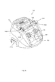
FIG. 7A illustrates a front perspective view of the vacuum head in accordance with an embodiment of the invention. -
FIG. 7B illustrates a rear perspective view of the vacuum head shown inFIG. 7A . -
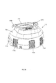
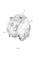
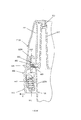
FIGS. 7C and7D illustrate bottom perspective views of the vacuum head shown inFIG. 7A . -
FIGS. 7E and7F illustrate the vacuum head shown inFIG. 7A , further attached to the separator plate. -
FIG. 8A illustrates a front perspective view of a latch device in accordance with an embodiment of the invention. -
FIG. 8B illustrates an exploded view of the latch device shown inFIG. 8A -
FIG. 8C illustrates a partial cross-sectional view of the vacuum system, showing the operation of the latch device shown inFIG. 8A . -
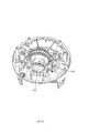
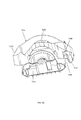
FIG. 9A illustrates an isolated view of a separator plate in accordance with an embodiment of the invention. -
FIG. 9B illustrates a top perspective view of the separator plate shown inFIG. 9A . -
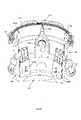
FIG. 9C illustrates a bottom perspective view of the separator plate shown inFIG. 9A . -
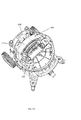
FIG. 10A illustrates a top perspective view of a valve assembly in accordance to an embodiment of the invention, the valve assembly being mounted on the separator plate ofFIG. 9A . -
FIG. 10B illustrates an isolated, front perspective view of the valve assembly shown inFIG. 10A . -
FIG. 10C illustrates an isolated, rear perspective view of the valve assembly shown inFIG. 10A . -
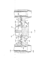
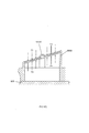
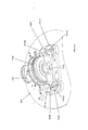
FIG. 10D illustrates a cross sectional view of a conduit and a valve of the valve assembly, showing the forces acting upon a disc. -
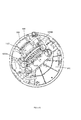
FIG. 11A illustrates an isolated view of an airflow assembly in accordance with an embodiment of the invention. -
FIGS. 11B and11C illustrate perspective views of the airflow assembly ofFIG. 11A mounted on the separator plate shown inFIG. 9A . -
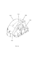
FIGS. 12A and12B illustrate the vacuum system with the vacuum head and manifold removed, showing a motor shroud mounted on the separator plate ofFIG. 9A . -
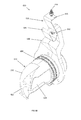
FIG. 13A illustrates a front perspective view of a manifold in accordance with an embodiment of the invention, shown in isolation. -
FIG. 13B illustrates a cross sectional view of the manifold shown inFIG. 13A . -
FIG. 13C illustrates a bottom perspective view of the manifold shown inFIG. 13A . -
FIG. 14A illustrates an exploded view of the tank and the manifold of the vacuum system, showing the positional relationship between the manifold and the separator plate ofFIG. 9A . -
FIGS. 14B and14C illustrate perspective views of vacuum system with the vacuum head removed for clarity, showing the manifold ofFIG. 13A mounted on the separator plate ofFIG. 9A . -
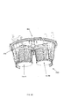
FIG. 15A illustrates a perspective view of a filter assembly in accordance with an embodiment of the invention, shown mounted on the separator plate ofFIG. 9A . -
FIG. 15B illustrates a cross sectional view of the filter assembly shown inFIG. 15A . -
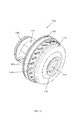
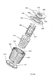
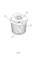
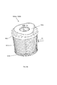
FIG. 16A illustrates an exploded view of a filter device in accordance with an embodiment of the invention. -
FIG. 16B illustrates a perspective view of the filter device shown inFIG. 16A . -
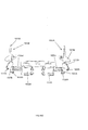
FIGS. 17A- 17C illustrate schematic views showing the operation of the airflow assembly. -
FIGS. 18A and18B illustrate a schematic views showing airflow through the filter device. -
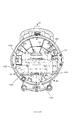
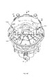
FIGS. 19A and19B illustrate a schematic views showing airflow through the airflow assembly. -
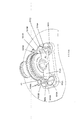
FIG. 20 illustrates an electrical diagram in accordance with an embodiment of the invention. - Like reference numerals have been used to identify like elements throughout this disclosure.
- Referring to
FIGS. 1A and1B , avacuum system 10 in accordance with an embodiment of the invention (e.g., a wet/dry vacuum cleaner) includes abody 100 having atank portion 105 coupled to a head orlid portion 110 via one ormore latch devices 112, as well as anoptional handle assembly 115. Thetank 105 may possess any dimensions and shapes suitable for its described purpose. In an embodiment, thetank 105 is generally cylindrical. In another embodiment, it may possesses a generally frustoconical shape. In the embodiment illustrated inFIGS. 2A and2B , thetank 105 includes acurved side wall 205, a closed lower end orbottom 207 and an open upper end ormouth 210. The interior surface of thetank bottom 207 may be generally concave, possessing a slightly upward curve to, e.g., prevent the tank from sagging when filled with a predetermined amount of debris. Thetank mouth 210 defines arim 212 configured to engage a corresponding shoulder forming the separator plate 900 (FIG. 9A ) inserted into the tank. Thetank rim 212 is may protrude radially outward from theside wall 205, thereby forming alip 213 about themouth 210 of thetank 105. With this configuration, thetank 105 defines an open cavity orcollection chamber 214 operable to collect and store debris drawn therein. - The
tank 105 further includes aforward handle 215 extending radially from the exterior surface of the side wall 205 (e.g., from the tank lip 213), and arearward bracket 217 extending radially from the exterior surface of theside wall 205 at a location that is generally diametrically opposed from the forward handle position 215 (e.g., the bracket is oriented approximately 180° from the handle). Thebracket 217, which couples thehandle assembly 115 to thetank portion 105, includes anelongated housing section 220, afirst sleeve 222A disposed along one side of the housing section, and asecond sleeve 222B disposed along the opposite side of the housing section. Eachsleeve arm FIG. 4A ) of thehandle assembly 115. Thebracket housing section 220 cooperates with thehousing section 420 of thehandle assembly 115 to define a housing for a handle lock mechanism, with thebracket housing section 220 forming the upper portion of the lock mechanism housing, and the handleassembly housing section 420 forming the lower portion of the lock mechanism housing. Thebracket housing section 220 includes anopening 225 through which the actuator 430 (FIG. 4D ) of the lock mechanism protrudes (discussed in greater detail below). - The
tank portion 105 further may further include one or more latch receptacles formed into theside wall 205. In an embodiment, theside wall 205 includes afirst latch receptacle 227A spaced (e.g., diametrically opposed) from asecond latch receptacle 227B, each being disposedproximate tank rim 212. Eachlatch receptacle projections tank 105. Eachprojection tank mouth 210, along the exterior surface of theside wall 205. Eachlatch receptacle corresponding latch device 112 operable to couple thetank 105 to the separator plate 900 (discussed in greater detail below). - The
vacuum 10 further includes a transport assembly that enables movement of the vacuum over a surface. By way of example, thevacuum 10 may include on or more wheel assemblies that couple to thetank 105. Referring to the embodiment shown inFIG. 2B , thetank 105 includes a plurality of notches orslots tank bottom 207. Eachnotch 235A - 235D is recessed into theside wall 205, being contoured to receive a corresponding connector on a wheel assembly. Specifically, thenotch 235A - 235D defines a dove tail, having anarrow neck portion 240 and a widenedbase portion 245 contoured to mate with a similarly shaped pin on the wheel assembly (discussed in greater detail below). Eachnotch 235A - 235D further includes a female coupling member or socket 250 (e.g., a generally cylindrical socket) adapted to receive a corresponding male coupling member disposed on the wheel assembly connector. - Referring to
FIGS. 3A - 3C, the wheel assembly may be in the form of acaster 305 including a top plate orsupport 310 and awheel 315 disposed along distal section of the support. Thewheel 315 is rotatably mounted to afork 320 that, in turn, is pivotally coupled to thesupport 310 via acentral pin 322. The proximal section of thesupport 310 includes aconnector 325 adapted to mate with one of thenotches 235A - 235D formed into thetank 105. In the illustrated embodiment, theconnector 325 is a pin extending axially from the proximal end of thesupport 310. The pin is contoured, including a narrow neck portion 330 (corresponding with theneck portion 240 of thenotch 235A - 235D) and a widened base or end portion 335 (corresponding with thebase portion 245 of the notch). A male coupling member or post 340 (e.g., a cylindrical post), extending from theend portion 335 of theconnector 325, is received by thetank socket 250. Thetank socket 250 may further include threaded channel operable to engage a threaded fastener that passes through thepost 340, securing thecaster 305 within thenotch 235A - 235D. Connection of thecaster 305 to thetank 105 is best seen inFIG. 5 . - Referring back to
FIG. 2A , thetank 105 further includes anintake port 255 formed into the side wall 205 (along the forward portion of the side wall). Avacuum connector 260, secured to the exterior side of theintake port 255, couples to ahose connector 265, which, in turn, couples to a flexible tube (e.g., a hose) utilized to capture debris. Anexterior cap 270, tethered to thevacuum connector 260, may be utilized to seal the port. The intake port, vacuum connector, hose connector, flexible tube, and cap may possess any shape and dimensions suitable for its intended purpose. By way of example, any of the intake port, vacuum connector, hose connector, flexible tube, and cap may be generally circular and/or cylindrical. An inlet device 600 (FIG. 6A ) may be secured to the interior side of the intake port 255 (discussed in greater detail below). - Referring to
FIGS. 4A - 4G , thehandle assembly 115 includes abase member 400, a firstupright arm 405A extending upward from the base, a secondupright arm 405B laterally spaced from the firstupright arm 405B, and a grippingmember 410 connecting the first arm to the second arm. The first 405A and second 405B arms, as well as thehandle 410, may possess any shape and dimensions, and may be formed of any materials suitable for their described purpose. By way of example, thehandle arms member 410 may be generally tubular and/or cylindrical. By way of further example, thehandle arms member 410 may be formed of steel tubing. In other embodiments, plastic may completely form, or may form portions of, the handle assembly. - Each
handle arm proximal portion 412A secured to thebase member 400 and an upper ordistal portion 412B telescopically coupled to the proximal arm portion such that the distal arm portion nests within the proximal arm portion. With this configuration, the height of the grippingmember 410 may be adjusted with respect to thebase member 400. Specifically, thehandle assembly 115 may reconfigured from a first, collapsed position (as shown in the figures) to a second, extended position (not illustrated). The grippingmember 410 is secured at a desired vertical or telescopic position via anarm lock mechanism 415 that cooperates with a plurality of apertures longitudinally (vertically) spaced along thearms distal portions 412B of thearms arm apertures 417A disposed proximate the longitudinal center of the armproximal portion 412B, as well as a second set ofarm apertures 417B disposed proximate the lower end of the armproximal portion 412B (seen best inFIG. 4B ). - As explained above, the handle
assembly housing section 420 cooperates with thebracket housing section 220 to form a lock mechanism housing that houses thelock mechanism 415. Referring toFIG. 4C , the handleassembly housing section 420 includes afirst sleeve 422A and asecond sleeve 422B laterally spaced from the first sleeve. Thefirst sleeve 422A of the handleassembly housing section 420 is configured to align with thefirst sleeve 222A of thebracket housing section 220. Similarly, thesecond sleeve 422B of the handleassembly housing section 420 aligns with thesecond sleeve 222B of thebracket housing section 220. - The handle
assembly housing section 420 further includes aguide block 425 centrally disposed within the housing section. Theguide block 425 is a generally planar element extending distally from the lower surface of the housing section interior. Apost 427 extends distally (upward) from the distal end of theguide block 425. Thepost 427 couples to a biasingmember 475 such as a spring that biases theactuator 430 in its normal position (discussed in greater detail below). The outer surface of the handleassembly housing section 420 may be contoured with features such as finger indentations to aid in the gripping of the housing during operation of the lock mechanism. - Referring to the embodiment illustrated in
FIG. 4D , theactuator 430 possesses a generally U-shaped configuration defined by anengagement portion 432 and acarriage portion 435. The transverse dimension of theengagement portion 432 may be less than the transverse dimension of thecarriage portion 435. That is, thecarriage portion 435 may be wider than theengagement portion 432 to form a shoulder or stop 437. With this configuration, theactuator 430 is trapped within thebracket housing section 220, and the extension of the actuator through theopening 225 is limited by contact between theshoulder 437 and thehousing section 420. That is, only theengagement portion 432 extends through theopening 225 since theshoulder 437 serves as a stop, preventing the extension of the actuator from theopening 225 beyond the shoulder. - The
carriage portion 435 includes a first orforward wall 440A and a second orrearward wall 440B that cooperate to define acavity 442 therebetween. Thecavity 442 receives theguide block 425 to permit the axial repositioning of theactuator 430 along theguide block 425. Thewalls carriage portion 435 each includes aligned, tapered (e.g., V-shaped)slots lateral side carriage portion 435. The slots 445 are defined by anupper projection 450 protruding slightly from thelateral side engagement portion 432, and alower finger 452 extending angularly from the lateral side at a distance greater than that of theprojection 450. - Referring to
FIG. 4C , thelock mechanism 415 further includes afirst lever 455A and asecond lever 455B operable to rotate within the lock mechanism housing. Thelevers hub 457, a first orhorizontal arm 460, and a second orvertical arm 462 oriented generally orthogonal to the first arm. Thehub 457 defines a central pivot point P about which eachlever first arm 460 of eachlever actuator 430. By way of example, the distal end of thefirst arm 460 may be enlarged such that spans the opening betweenforward 440A andrearward walls 440B, extending from theslot 445A formed into theforward wall 440A to theslot 445B formed into therearward wall 440B. With this configuration, the movement of the actuator 430 (i.e., the axial/vertical movement of thecarriage portion 435 along the guide block 425) causes a corresponding rotation of eachlever - The
second arm 462 of the first 455A and second 455B levers are configured to drive locking pins that engage the arms of thehandle assembly 115. Specifically, thefirst lever 455A is in communication with afirst locking pin 465A and thesecond lever 455B is in communication with asecond locking pin 465B. Thefirst locking pin 465A extends from the firstlateral side 447A of theactuator carriage portion 435 to thefirst arm 405A. Similarly, thesecond locking pin 465B extends from the secondlateral side 447B of theactuator carriage portion 435 to thesecond arm 405B. The distal (arm facing) portion of eachpin arm apertures arm - Each locking
pin pin actuator 430, to a second, extended position, in which the locking pin is driven outward from the actuator and the distal portion of the pin engages the aperture of 417A, 417B its associatedarm second arm 460 of eachlever pin socket second lever arm 462 is received within asocket lever locking pin lever - The operation of the
lock mechanism 415 is explained with reference toFIGS. 4F and4G . Theactuator 430 is spring biased in its normal (e.g. upward) position by a biasing member 475 (e.g., a spring). In this normal position, the locking pins 465A, 465B are oriented in their extended position, in which the distal end of each pin extends through theaperture distal portion 412B. In this configuration, movement of thedistal arm portion 412B with respect to theproximal arm portion 412A is prevented, locking thehandle 410 at a first vertical height. Theactuator 430 is engaged by pressing theengagement portion 432 downward (indicated by arrow F) to overcome the biasing force of the biasingmember 475. As a result, thecarriage portion 435 is driven axially downward, sliding along theguide member 425. In turn, thefirst arms 460, captured within thecarriage slots levers FIGS. 4F and4G , when theactuator 430 is urged downward, thefirst lever 455A rotates clockwise, while thesecond lever 455B rotates counterclockwise. - This rotation further causes
second arms 462 to rotate inward (toward the actuator 430), thereby driving the locking pins 465A, 465B inward, from the extended pin position to the retracted pin position (indicated by arrow T). That is, the distal portion of each lockingpin aperture corresponding arm distal arm portion 412B is free to telescope into and out of theproximal arm portion 412A, and the height of thehandle 410 with respect to the base 400 (indicated by arrow M) may be adjusted. By way of example, thedistal arm portion 412B may telescope outward from a first arm position, in which the locking pins 465A, 465B are aligned with thefirst arm apertures 417A, to a second arm position, in which the locking pins are aligned with thesecond arm apertures 417B. Releasing theengagement portion 432 permits the biasingmember 475 to return theactuator 430 to its normal position, driving thecarriage portion 435 upward and rotating thelevers levers handle 410 at a second vertical height. - Referring back to
FIG. 4A , thebase member 400 may further includewheels connectors notches tank 105, as shown inFIG. 5 . - As mentioned above, the
tank 105 further includes an inlet device adapted to direct the flow of air and debris entering the collection chamber. Referring toFIGS. 6A - 6C, theinlet device 600 includes astem portion 605 coupled to theintake port 255 and abaffle portion 610 including a closeddistal end 615 with acurved fin 620 and awindow 625 formed into the side wall of the baffle. Thestem portion 605 may be generally cylindrical, extending radially inward from theside wall 205 inner surface. Thebaffle portion 610 is configured to deflect incoming air and debris as it travels through the conduit. By way of example, thebaffle 610, via thefin 620, alters the travel path of contaminated fluid (air/water with debris) approximately 90° such that the fluid is directed radially outward, toward theside wall 205 of thetank 105. - The
inlet device 600 further includes an electrostatic charge system operable to connect the inlet device to the ground of the main power supply. Contaminated fluid (e.g., debris-laden air) moving through the hose, the hose connector, the vacuum connector, and/or the inlet device often produces a build-up of electrostatic discharge in thevacuum system 10. This poses of risk of electrical shock to the user. Consequently, thevacuum system 10 may further include an electrostatic discharge device that connects the electrical ground of the vacuum to the hose system. The electrostatic discharge device includes a support orextension 630 coupled to a conductive member 635 (e.g., a flat copper spring) having aproximal portion 645 and adistal portion 650. Afirst metal fastener 640 connects theconductive member 635 to thesupport 630. - A
second metal fastener 655, moreover, connects thedistal portion 650 of theconductive member 635 to theseparator plate 900, with the conductive member being disposed within aprotrusion 990 extending downward from the separator plate (FIG. 9C ). Theinlet device 600, moreover, may be formed of an electrically conductive material (e.g., electrically conductive plastic). With this configuration, the static discharge system creates an electrically conductive path that allows static charge from the hose, the hose connector, etc., to travel through the intake device, along the extension, up through the conductive member and to the main electrical ground. - The interior of the
tank 105 may further be keyed such that the separator plate 900 (discussed below) couples to the tank in a single rotational orientation. Referring specifically toFIG. 6A , theinterior surface 670 of thetank side wall 205 includes a first guide rib orelement 675A and a second guide rib orelement 675B. Theguide elements interior surface 670, are disposed at predetermined angular positions along theside wall 205 such that the guide elements align with slots formed into theforward legs 907A, 970B of the separator plate 900 (FIG. 9C ). As such, theseparator plate 900 may be inserted into the tank cavity in a predetermined orientation, with platform of the being disposed in a particular rotational position with respect to the collection chamber (i.e., one in which the slot formed into each of the two forward legs of the separator plate align with acorresponding guide element - Referring to
FIGS. 7A and7B , thevacuum head 110 includes ashell 705 including axial connection posts 707 disposed at predetermined locations along head interior surface. Eachhead post 707 aligns with acorresponding post 917 disposed on the separator plate 900 (FIG. 9A ). The distal end ofplate post 917 may include a receptacle that receives the distal end of thehead post 707. A fastener may pass through theposts vacuum head 110 to theseparator plate 900. Thevacuum head 110 further includes a pair of opposed handle openings or cut-outs shell 705. Each handle cut-out 710A, 710B, defined by a downward-extendingwall 712, defines a cavity within thevacuum head 110 that receives the hook portion of thelatch device 112, as well as exposes a portion of the separator plate such that it may be engaged by the hook portion (explained in greater detail below). When coupled to the tank, each cut-out 710A, 710B generally aligns with an associatedlatch receptacle - The
vacuum head 110 may further include one or more vents disposed at predetermined locations along the shell. In the illustrated embodiment, thevacuum head 110 includes a first or vacuum discharge vent 715A (aligned with the vacuum exhaust), a second ormotor intake vent 715B (aligned with the motor air intake), and a third ormotor discharge vent 715C (aligned with the motor exhaust). Eachvent vacuum head 110. Eachvent 710A - 710C includes anopen chute 716 formed into theshell 705 that receives acorresponding louver assembly 717. By way of example, eachlouver assembly 717 may slide axially into and out of theopen chute 716. Thelouvers 717 may be configured to direct air any desired direction. - The
head 110 further houses the electrical and electronic components of thevacuum system 10; consequently, it includes a control panel ordashboard 720 and one or more actuators 725 (e.g., a control knob) operable to control the operational parameters of the device, including, but not limited to, power (ON/OFF) and the fan speed of the motor. The dashboard may further include anoutlet 727 to which a power cord may be connected. The electrical components may be controlled via a circuit board 729 mounted to the interior surface of thedashboard 720. - The
head 110 further includes a handle or grippingmember 730 to aid in separation of thehead 110 from thetank portion 105. The firstlateral side 735A of thehandle 730 includes a firstlateral extension 740A. Similarly, the secondlateral side 735B of thehandle 730 includes a secondlateral extension 740B. Eachlateral extension handle 730 provides a coupling area that enables the wrapping of a cord around the handle (e.g., the electrical cord of the vacuum system 10). - As noted above, one or
more latch devices 112 couples theseparator plate 900 to thetank 105. Referring toFIGS. 8A - 8C , alatch device 112 includes a gripping member orbody 805 and alocking mechanism 810 coupled to the inner (tank facing) side of the gripping member. Thelatch body 805 includes alower handle portion 815 and anupper hook portion 820 configured to engage a lip disposed on theseparator plate 900. The exterior side of the grippingmember 805 further includes anextension 825 extending angularly outward from the upper end of thehandle portion 815. - The
locking mechanism 810 may be any conventional lock mechanism suitable for its described purpose. By way of example, thelocking mechanism 810 may include apivot member 830 pivotally coupled via alower pin 835A to the handle portion 815 (by way of handle apertures 837) and pivotally coupled to abracket 840 via anupper pin 835B (by way of bracket apertures 842). Thebracket 840, in turn, is coupled to thetank 105 viaplate member 845. Thebracket 840 and theplate member 845 include connection holes 847 that receive fasteners such as bolts. Thepivot member 830 is biased via a biasing member 850 (e.g., a spring) configured to draw thehook portion 820 downward when the grippingmember 805 is positioned in its normal, locked position. - In operation, the
latch device 112 begins in its normal, locked position, in whichhook portion 820 is positioned within a handle cut out 710A, 710B such that thehook portion 820 engages thelip FIG. 9A ). Thehandle portion 215, moreover, is positioned within alatch receptacle hook portion 820, being held into engagement with thetank rim 212. To release thelatch device 112, the lower end of thehandle portion 815 is pivoted outward (away from thetank 105, indicated by arrow Z) to overcome the biasing force ofspring 850 in thelocking mechanism 810. In this manner, the grippingmember 805 is moved from its normal, locked position to its unlocked position (not illustrated). In the unlocked position, thehook portion 820 is no longer held taut againstlip separator plate 900. Thehook portion 820 may be manipulated further by grasping theextension 825 maneuvering it to completely disengage thehook portion 820 from thelip member 805 such that it clears the handle cut-outs lid 100. - To secure the
latch device 112, the reverse process is followed, with thehook portion 820 being positioned on the lip, e.g., via manipulation of theextension 825, and thehandle portion 815 being rotated inward (toward the tank) to draw thehook portion 820 downward into tight contact with thelip - Referring to
FIGS. 9A - 9C , aseparator plate 900 engages thetank rim 212, separating the tank cavity 214 (the collection chamber) from the cavity of the vacuum head 110 (also called a motor chamber). Theseparator plate 900 includes a platform 905 (e.g., a generally circulate plate) and one ormore leg members 907A-907D. Theplatform 905 includes an upper (head facing)surface 910 and a lower (tank facing)surface 912. The shaped and dimensions of theplatform 905 may be any suitable for its described purpose. By way of example, theplatform 905 may be substantially planar and possess a generally circular shape. Aperimetral wall 915, protruding upward from the platformupper surface 910, extends about the circumference of theplatform 905. As noted above, theupper surface 910 of theplatform 905 may further include one ormore connection posts 917 that engage (e.g., mate, receive, etc.) corresponding connection posts 707 extending from thevacuum head 110. Fasteners may extend through the connection posts 707, 917 to secure thelid 110 to theseparator plate 900. A pair of diametricallyopposed lips perimetral wall 915 to provide an engagement member for each of thelatch devices 112, as described above. Theplatform 905 may further include one or more reinforcingribs 921 spanning the platformupper surface 910 to enhance the strength of the platform. - The
leg members 907A - 907D, extending distally from the platformlower surface 912, are configured to elevate theplatform 905 and, in particular, to suspend the filter system above a supporting surface when the separator is placed directly upon the supporting surface. That is the length of the legs is selected to prevent the filters from contacting the ground when theseparator plate 900 and/orhead 110 is removed from the tank and set on a surface (seen inFIGS. 7E and15A ). Theleg members 907A - 907D are located proximate the outer edge of the separator plate, being disposed a predetermined angular positions thereon. - The
leg members 907A - 907D, moreover, are configured to key theseparator plate 900 to thetank 105 such that the separator plate is oriented in a specific rotational position when inserted into thetank 105. As shown in the figures, theplatform 905 includes a firstforward leg 907A, a secondforward leg 907B, a firstrearward leg 907C, and a secondrearward leg 907D. Eachleg 907A - 907D includes aproximal leg portion 922 and adistal leg portion 925. Theproximal leg portion 922 of theforward legs guide element interior surface 670 of thetank 105. As explained above, theguide element tank guide elements 675A. 675B such that thefirst guide element 675A is received within the notch of the firstforward leg 907A and thesecond guide element 675B is received within the notch of the secondforward leg 907B. Consequently, in order for theseparator plate 900 to be inserted into the tank cavity, thenotch 927A offirst leg member 907A must be aligned with thefirst guide element 675A and thenotch 927B of thesecond leg member 907B must be aligned with thesecond guide element 675B. Should the forward (notched)leg members corresponding guide elements separator plate 900 differ from the normal/predetermined position such that no leg or an unnotched leg is aligned with the guide elements), insertion of theseparator plate 900 into thetank cavity 214 will be prohibited. - The
separator plate 900 further includes a conduit system to enable the flow of air between the tank 105 (the collection chamber 214) and the head 110 (the motor chamber). In the embodiment illustrated, theplatform 905 of theseparator plate 900 includes a central, raised platform ordeck 902 with a first conduit pair 935 and a second conduit pair 940. The first conduit pair 935 includes a first (forward) suction conduit orport 935A and a first (rearward) cleaning conduit orport 935B. Similarly, the second conduit pair 940 includes a second (forward) suction conduit orport 940A and a second (rearward) cleaning conduit orport 940B. Theconduits first filter 1505A (FIG.15 ) of the filter system, while theconduits second filter 1505B of the filter system (i.e., each filter is in fluid communication with a conduit pair). - The
conduits conduit FIG. 9A , thesuction conduit inboard conduit baffle 942A that curves radially inward with respect to theplatform 905 to direct the air inboard, while the cleaningconduits outboard conduit baffle 942B that curves radially outward to direct air outboard (toward the perimeter of the platform). - The
upper surface 910 of theplatform 905 further includes first 945A, second 945B, and third 945C support walls that cooperate to support the airflow assembly. As shown, thefirst support wall 945A extends upward from theupper surface 910 of theplatform 905, being oriented between thesuction cleaning second support wall 945B is disposed proximate thecleaning conduits third support wall 945C, moreover, is positioned outboard from thesecond support wall 945B. Eachsupport walls 945A - 945C is spaced from its adjacent support wall to define a cavity therebetween. Specifically, the first 945A and second 945B support walls define afan cavity 950 that receives the fan of the airflow assembly. Similarly, the second 945B and third 945C support walls cooperate to define amotor cavity 955 that receives the motor of the airflow assembly. Eachsupport wall section 947 that receives and supports various components of the airflow assembly. By way of example, the second and third support walls cooperate to support the motor of the airflow assembly, with the motor resting within the cut-out section. Themotor cavity 955 further includesareas 957 for supporting valve solenoid switches (discussed in greater detail below). - The
separator plate 900 further includes a pair of opposedmotor intake walls 958 extending from thethird support wall 945C to theperimetral wall 915. Themotor intake walls 958 cooperate with a motor shroud 1205 (FIG. 12A ) to define a motorair intake area 960 that aligns withsecond head vent 715B. Similarly, opposedwalls 962 cooperate with themotor shroud 1205 to define amotor exhaust area 965 that aligns withthird head vent 715C. - A deflection wall or baffle 970 extends upward from platform upper surface 910 (e.g., the height of the wall may be substantially equal to or greater than the height of the deck 902). The
platform baffle 970 is positioned between thedeck 902 and theperimetral wall 915. Theplatform baffle 970 gradually curves such that it extends from a position along a lateral side of thedeck 902 to a position along the forward side of the deck. Theplatform baffle 970 is operable to direct cooling air exhausted by the manifold 1305 (FIG. 13A ) toward electronics housed within thehead 110, thereby cooling the electronics (discussed in greater detail below). - The
platform 905 further includes afirst yoke 975A located proximate thefirst cleaning conduit 935B and asecond yoke 975B located proximate thesecond cleaning conduit 940B. Eachyoke butterfly valve FIG. 10A ) of the valve assembly to enable rotation of the valve on the yoke (discussed in greater detail below). - The platform
lower surface 912 is best seen inFIG. 9C . As shown, platformlower surface 912 includes a recessedarea 977 generally corresponding with the raiseddeck 902 of the platformupper surface 910. Theperimetral wall 915 of the platformupper surface 910, moreover, defines ashoulder 980 on the platformlower surface 912. Anaxial wall 982 extends downward from thelower surface shoulder 980, being disposed slightly inboard from the circumference of theseparator plate 900. The axial wall 982 (FIG. 8C ) is wrapped with a generally U-shaped sealing member orgasket 983 configured to contact therim 212 of thetank 105 and thereby fluidly seal the joint between thetank rim 212 and theshoulder 980. - A series of downward-extending,
angled fins 985 may be angularly spaced about theplatform 905, being located near the outer edge of the platform, proximate theshoulder 980. Thefins 985 serve as guides during the insertion of theseparator plate 900 into thetank cavity 214. Abracket 990 is also disposed on the platformlower surface 912 that receives theconductive member 635 of the electrostatic discharge device. As shown, theconductive member 635 is coupled to theplatform 905 via theconductive fastener 655. - A valve assembly, disposed on platform
upper surface 910, opens and closes one or more of theseparator conduits FIGS. 10A - 10C , thevalve assembly 1000 includes afirst solenoid 1002A in communication with to afirst butterfly valve 1005A and asecond solenoid 1002B in communication with to asecond butterfly valve 1005B. Thefirst butterfly valve 1005A is supported by thefirst platform yoke 975A, while the second butterfly valve is supported by thesecond platform yoke 975B. As seen inFIG. 10A , thevalve assembly 1000 is positioned on theseparator plate 900, with eachsolenoid areas 957 as described above. Thesolenoids platform 905 by a cover orbridge 1040 coupled thereto. - The
first butterfly valve 1005A selectively permits airflow through thefirst conduit pair second butterfly valve 1005B selectively permits airflow through thesecond conduit pair butterfly valve elongated shaft distal disc 1015A and a second orproximal disc 1015B longitudinally spaced along the shaft and rotationally offset from the distal disc by, e.g., approximately 45°. - The proximal end of the
shaft arm member pivot pin member plunger solenoid plunger member ski upper surface 910 as theplunger ski plunger solenoid solenoid shaft - As a result, the
valve assembly 1000 may selectively position eachdisc conduit valve assembly 1000 rotationally positions thediscs suction conduits conduits butterfly valve shaft first disc 1015A is oriented generally transverse to the opening defined by thesuction conduit FIG. 10A ), thereby permitting airflow between the tank 105 (the collection chamber 214) and the head 110 (the motor chamber). Thesecond disc 1015B, meanwhile, is positioned such that the disc completely covers the opening of thecleaning conduit head 110 to thetank 105. Alternatively,, thevalves discs suction conduits conduits - As shown in
FIG. 10D , theconduits discs butterfly valve disc valve disc - An airflow assembly, housed within the motor chamber defined by
head 110 and supported on theupper platform surface 910, generates air pressure (positive and/or negative), within thevacuum device 10, as well directs the flow of air within thehead 110. Referring toFIGS. 11A - 11C , the airflow assembly includes anairflow generating device 1102 having acentrifugal fan 1105 driven by amotor 1107. Thefan 1105 includes an annular housing orbaffle 1110 and a plurality ofslots 1112 disposed about the perimeter of the housing. Theslots 1112 may be angled (e.g., offset and/or nonparallel to the rotational axis of the housing) to direct air in a predetermined direction. With this configuration, air is drawn into thecentral channel 1115 and is directed radially outward (from the fan rotational axis) through theslots 1112. Theairflow generating device 1102 may further include aforward gasket 1122 coupled to the forward (inboard facing) side of thefan 1105, and amanifold spacer 1125 coupled to the rearward side of the fan. Themotor 1107 may include any type of motor suitable for its described purpose. By way of example, themotor 1107 may include a universal series motor with acentral channel 1127. Themotor 1107 is configured to drive (e.g., rotate) thefan 1105 in a clockwise and/or counterclockwise direction, as well as to draw cooling air into themotor channel 1127. In an embodiment, themotor 1107 rotates thefan 1105 in a predetermined direction to generate a negative pressure within thevacuum device 10, which, in turn, generates a suction airstream (an intake airstream) that enters thetank portion 105 via theinlet port 255. As illustrated, the forward side of themotor 1107 may be coupled to the rearward (outboard facing) side of thefan 1105, and arearward gasket 1130 may be coupled to the outboard side of the motor. - Referring to
FIGS. 11B and11C , theairflow generating device 1102 is oriented on theseparator plate platform 905 such that it is located between thebutterfly valves fan 1105 andmanifold spacer 1125 being positioned within thefan cavity 950 of theplatform 905, as well as aligned with the cut outsection 947 formed into the first 945A and second 945B walls. Themotor 1107, moreover, is position withinmotor cavity 955 such that themotor channel 1127 is aligned with the cut-out sections formed into the second 945B and third 945C platform walls. In a preferred embodiment, thefan 1105 is oriented such that its rotational axis R is oriented generally horizontally, i.e., such that the rotational axis is generally parallel to theplatform 905 of theseparator plate 900. Stated another way, the fan rotational axis R is oriented generally transverse (e.g. orthogonal) to the longitudinal axis of afilter FIG. 15 ). As such, the air intake direction of thefan 1105 may be oriented generally transverse (e.g., generally orthogonal) to the airflow passing through the conduit pairs 935, 940. - Referring to
FIGS. 12A and12B , themotor 1107 is housed in amotor shroud 1205 defining a motorair intake port 1210 and a motor air outlet orexhaust port 1220. Themotor shroud 1205 separates the cooling airstream generated by the motor from the vacuum airstream. Theintake port 1210 cooperates withwalls 958 on theplatform 905 to define themotor intake area 960 as described above. Similarly, theexhaust port 1220 cooperates with thewalls 962 on the platformupper surface 910 to define themotor exhaust area 965 as described above. In operation, the ambient air is drawn into themotor air intake 1210, travels over the motor (cooling it), and is then exhausted viamotor air exhaust 1220. - The airflow assembly further includes a manifold operable to direct the airflow in predetermined directions. The manifold includes a plurality of chambers that function as baffles, cooperating to direct airflow in predetermined directions. Referring to
FIGS. 13A - 13C , themanifold 1305 includes aforward inlet chamber 1310, an intermediatefan discharge chamber 1315, and arearward exhaust chamber 1320. Theexhaust chamber 1320 includes anexhaust port 1325 to permit exhaust of the filtered air from themanifold 1305. In addition, thefan discharge chamber 1315 includes a first window oropening 1330 configured to permit the flow of fluid between thefan discharge chamber 1315 and theexhaust chamber 1320. Additionally, thefan discharge chamber 1315 includes a second window oropening 1335 including aninterior deflector 1337 extending angularly inward into the fan discharge chamber such that directs a portion of the air flowing downstream, through the manifold out of the manifold and into the cavity defined by thehead 110. - Referring to
FIGS. 14A - 14C , once coupled to theseparation plate 900, theinlet chamber 1310 is positioned over thesuction conduits discharge chamber 1315 is positioned over thefan 1105 and the cleaningconduits exhaust chamber 1320 is positioned over themotor shroud 1205. The operation of the manifold 1305 is discussed in greater detail below. - The
vacuum device 10 includes a filter assembly that captures particles within the contaminated airstream entering thetank 105, cleaning the airstream as the airstream flows through thebody 100 of thevacuum device 10. In the embodiment illustrated inFIGS. 15A and15B , thefilter assembly 1500 includes afirst filter 1505A and asecond filter 1505B. Thefilters lower surface 912, being generally radially aligned along opposite sides of plate center point and suspended above the floor of thetank 105. Additionally, as best seen inFIG. 15B , eachfilter conduits first filter 1505A is in fluid communication with the first conduit pair 935, whilesecond filter 1505B is in fluid communication with second conduit pair 940). - Referring to embodiment illustrated in
FIGS. 16A and16B , eachfilter inner cage 1605 generally concentrically disposed within a core member orouter cage 1610. Theinner cage 1605, which houses aball float 1612, may be generally cylindrical. Theouter cage 1610, which formed of wire screen, may possess a generally frustoconical shape. The outer cage is generally rigid, providing stiffness from end to end such that it can be threadingly tightened along one of the ends to an end cap. Specifically, the lower (narrower) terminus of theouter cage 1610 couples to alower end cap 1615, while the upper (wider) terminus of the outer cage couples to anupper end cap 1620. Thelower end cap 1615 may be in form of a solid, circular plate with an exterior wall extending upward from the plate and extending about its periphery, as well as an inner wall orrib 1622 concentric with the outer wall and configured to engage thecore member 1610 lower end. Theupper end cap 1620 may be generally annular, including a plurality ofratchet teeth 1625 disposed along on its upper side (being angularly spaced about the perimeter of the cap). Theinner channel 1630 of theupper end cap 1620, moreover, is threaded to mate with corresponding threads on a filter mount 1635 (discussed in greater detail below). - A
filter medium 1640 operable to remove particulates from the airstream is mounted on theouter cage 1610. As shown, thefilter medium 1640 may in the form of a sleeve including ahollow channel 1642 defined by the interior surface of awall 1643 and a plurality oflongitudinal fins 1644 angularly spaced about the exterior surface of the wall. Thefilter medium 1640 may possess a shape and dimensions that enable it to contour to the exterior surface of the outer cage 1610 (e.g., the filter may be generally frustoconical). By way of specific example, thefilter medium 1640 may possess an upper (wide end) diameter of approximately 6.4 inches, a lower (narrow end diameter) of approximately 5.25 inches, and a length (height) of approximately 5.2 inches. It should be understood that thefilter medium 1640 may possess any suitable shape and dimensions, and may be formed of any material an have any structure suitable for its described purpose. - The
filter mount 1635, secured to thelower surface 912 of the separator plate 900 (e.g., via fasteners), couples to theupper end cap 1620. Thefilter mount 1635 includes a seat member 1655 (e.g., a ball seat), abase 1660, and a threadedplug 1665 that engages the threads of theinner channel 1630 of theupper end cap 1620. Achannel 1670 is formed into thefilter mount 1635 to permit airflow from the filter to its associated conduit pair 935, 940. - The operation of the
vacuum device 10 is explained with references toFIGS. 17A - 17C andFIGS. 18A - 18C. Themotor 1107 is activated (e.g., viacontrols 725 on dashboard 720), rotating thefan 1105. Thefan 1105 creates a vacuum (suction) airflow within thebody 100 of thevacuum device 10. Referring toFIGS. 17A and18A , in a first operational mode, the butterfly values 1005A, 1005B are positioned in their normal, full suction position. In this position, thevacuum device 10 generates suction airflow that is filtered through thefilter medium 1640 of eachfilter butterfly valves first suction conduit 935A and thesecond suction conduit 940A are opened, and both thefirst cleaning conduit 935B and thesecond cleaning conduit 940B are closed. As a result, thefan 1105 draws contaminated air A1 including debris (particulate material) into the tank 105 (e.g., via an inlet/hose). The contaminated air A1 travels through thecollection chamber 214 and is drawn toward thefilters filter medium 1640 in a first filter direction, with the air entering the filter medium via the medium exterior surface. As the contaminated air A1 passes through thefilter medium 1640 of thefilters tank 105, while smaller debris becomes attached and/or embedded within thefilter medium 1640. This airstream, now filtered air A2, passes upward, through the central channel of the filter (as defined by inner cage 1605) and toward thesuction conduit - The filtered air A2 passes through the
suction conduit tank 105 and into the motor chamber defined by thevacuum head 110. Specifically, the filtered air A2 enters themanifold 1305 of the air assembly disposed within the motor chamber, entering theinlet chamber 1310. The filtered air A2 is drawn into the fancentral aperture 1115 and is directed radially outward therefrom as fan exhaust or discharge air A3 (indicated by arrows). The discharge air A3 is directed, via theslots 1112, into themanifold discharge chamber 1315. Thecleaner conduits discharge chamber 1315, through thefirst window 1330, and into theexhaust chamber 1320. Additionally, a portion of the discharge air A3 is deflected bymanifold deflector 1337 such that it passes through thesecond window 1335. As such, a portion of the discharge air A3 exits the manifold 1305 (and the vacuum system 10) as manifold exhaust air A4 viamanifold exhaust outlet 1325. Additionally, a portion of the discharge air is recycled as electronics coolant A3', exiting themanifold 1305 and returning to the motor chamber defined by thehead 110 to cool electronics housed in the head (discussed in greater detail below). - Referring to
FIGS. 17B and18B , in a second operational mode, thefilter medium 1640 of thefirst filter 1505A is purged of debris. In this mode, thefirst butterfly valve 1005A is engaged to reorient the valve from its normal position to its purge position. Specifically, thefirst rod 1010A is rotated such thatdistal disc 1015A covers/seals thefirst suction conduit 935A and theproximal disc 1015B is positioned such that it is oriented generally transverse to the opening of thefirst cleaning conduit 935B. In this configuration, thefirst cleaning conduit 935B is opened, while thefirst suction conduit 935A is closed/sealed. Thesecond butterfly valve 1005B remains in its normal position as described above, with thesecond suction conduit 940A being opened and thesecond cleaning conduit 940B being closed/sealed. - In this configuration, the suction airflow through the
first filter 1505A ceases. That is, contaminated air A1 no longer passes through thefilter medium 1640 of thefirst filter 1505A via the filter medium exterior surface. Suction airflow through thesecond filter 1505B, however, is maintained. The filtered air A2 from thesecond filter 1505B enters the manifold 1305, where it is drawn into thefan 1105 and expelled throughfan slots 1112 as discharge air A3. With thecleaning conduit 935B in its opened position, at least a portion of the discharge air A3 is directed downward, into thefirst cleaning conduit 935B (indicated by arrow). The discharge air A3 enters the central channel of thefirst filter 1505A (as defined by the inner cage 1605) and is forced radially outward, passing through thefilter medium 1640 in a second filter direction. As shown inFIG. 18B , this outward airflow functions as a purging airflow effective to dislodge at least a portion of the debris and/orparticles 1800 previously attached to and/or embedded within thefilter medium 1640. Any remaining discharge air A3 (i.e., and discharge air not directed into thecleaning conduit 935B) is directed as indicated above, being expelled from the tank as either manifold exhaust A4 or being recycled as electronics coolant A3'. - In a third operational mode, the
filter medium 1640 of thesecond filter 1505B is purged. The same operation described above with regard to thefirst filter 1505A occurs with thesecond filter 1505B. Referring toFIGS. 17C and18B , thefirst butterfly valve 1005A is returned to its normal position, in which thefirst suction conduit 935A is opened andfirst cleaning conduit 935B is sealed/closed. In addition, thesecond butterfly valve 1005B is engaged, moving the valve from its normal position to a purge position, in which thesecond suction conduit 940A is closed and thesecond cleaning conduit 940B is opened. Similar to that described above, discharge airflow A3 drawn into the manifold 1305 as filtered air is either directed into thesecond cleaning conduit 940B, out of the head 1010 via themanifold exhaust chamber 1320, or back into the head 1010 via second window 1035. The discharge air A3 that is directed through the cleaning conduit passes through thefilter medium 1640 of thesecond filter 1505B in a second direction (opposite the first direction), thereby purging the filter medium of debris captured thereon. - The amount of time for the purge is not particularly limited. By way of example, the airflow system may operate in the suction mode for a first predetermined period of time and in the purging/cleaning mode for a second predetermined period of time, with the second period of time being less than the first period. In an embodiment, the valve system cycles, generating suction air for approximately 30 seconds, and then generating purge air for approximately 0.3 seconds, alternately purging the
first filter 1505A and the second filter 705B. This process continues, with thefilters - Referring to
FIGS. 19A and19B , during operation, cooling air A5 for the motor 1007 is drawn in through themotor intake port 1210 of themotor shroud 1205, where it is directed across the motor, cooling it, and then out throughmotor exhaust 1220 as motor exhaust air A5'. As mentioned above, the motor airflow A5, A5' remains separate from the vacuum airflow A1, A2, A3, A3', A4 vacuum filtered air, with the motor shroud preventing the motor air A5, A5' from entering themanifold 1305. -
FIG. 20 illustrates an electrical schematic for thevacuum device 10 in accordance with an embodiment of the invention. As shown, theelectrical system 2000 includes amicroprocessor 2005 in communication with the motor viamotor connect 2010, as well as thebutterfly valves 1005, 1005B via asolenoid connect 2015, which, in turn, is in communication withsolenoid switches system 2000 may further include a pressure orflow sensor 2020 operable to indicate when the intake airflow A1 is reaches (e.g., is above or below) a predetermined threshold value. By way of example, it may indicate when the airflow pressure or flow velocity is below a specified value, thereby notifying the user that the filters must be removed for manual cleaning or replacement. - While the present invention has been described in detail and with reference to specific embodiments thereof, it will be apparent to one skilled in the art that various changes and modifications can be made therein without departing from the spirit and scope thereof. Thus, it is intended that the present invention covers the modifications and variations of this invention provided they come within the scope of the appended claims and their equivalents. It is to be understood that terms such as "top", "bottom", "front", "rear", "side", "height", "length", "width", "upper", "lower", "interior", "exterior", and the like as may be used herein, merely describe points of reference and do not limit the present invention to any particular orientation or configuration.
Claims (15)
- A vacuum device comprising:a tank portion including a collection chamber;a head portion including an airflow chamber;a filter disposed within the tank collection chamber;an airflow assembly disposed within the airflow chamber, the airflow assembly including:an airflow generating device operable to generate airflow within the vacuum device such that an intake airstream is drawn into the collection chamber via an air inlet and an exhaust airstream is exhausted from the airflow chamber via an exhaust outlet,a first conduit in fluid communication with the filter, the first conduit directing airflow between the collection and airflow chambers, anda second conduit in fluid communication with the filter, the second conduit directing airflow between the airflow and collection chambers; anda valve assembly operable to selectively permit the airflow through either the first conduit or the second conduit.
- The vacuum device of claim 1, wherein:the filter defines a central filter axis;the device operates in a first mode, in which air is drawn inward, toward the filter axis; andthe device further operates in a second mode, in which air is directed outward, away from the filter axis.
- The vacuum device of claim 2, wherein:the device operates in the first mode for a first period of time;the device operates in the second mode for a second period of time; andthe second period of time differs from the first period of time.
- The vacuum device of claim 1, wherein:the airflow generating device comprises a fan rotating about a fan rotational axis; andthe fan rotational axis is oriented generally orthogonal to the filter axis.
- The vacuum device of claim 1, wherein the valve assembly comprises a butterfly valve including a first disc configured to selectively open and close the first conduit and a second disc operable to selectively open and close the second conduit.
- The vacuum device of claim 1, wherein:the filter is a first filter;the first and second conduits are in fluid communication with the first filter;the valve assembly is a first valve assembly; andthe vacuum device further comprises:a second filter disposed within the collection tank,a third conduit in fluid communication with the second filter,a fourth conduit in fluid communication with the second filter, anda second valve assembly operable to selectively permit suction airflow through the third conduit and the exhaust airstream through the fourth conduit.
- A vacuum device comprising:a body comprising a collection chamber and an airflow chamber;a separator disposed within the body, the separator separating the collection chamber from the airflow chamber, wherein the separator plate comprises:a platform including a first conduit adjacent a second conduit, each conduit providing fluid communication between the collection chamber and the airflow chamber, andan air generating device disposed on the separator platform; anda filter assembly disposed within the collection chamber,wherein contaminated air enters the collection chamber of the body, passes through the filter, and enters the airflow chamber as filtered air via the first conduit.
- The vacuum device of claim 7, wherein the filter assembly comprises a central channel coupled to the separator platform such that the central channel is generally aligned with the first and second conduits.
- The vacuum device of claim 7, further comprising a switch mechanism configured to selectively open and close each of the first and second conduits.
- The vacuum device of claim 9, wherein the switch mechanism comprises a butterfly valve including a first disc disposed over the first conduit and a second disc disposed over the second conduit, wherein the first disc is rotationally offset from the second disc.
- The vacuum device of claim 7, wherein the first and second discs are connected to a rod rotated from a first position, in which the first conduit is opened and the second conduit is closed, to a second position, in which the first conduit is closed and the second conduit is opened.
- The vacuum device of claim 7, wherein:the filter assembly is a first filter assembly;the separator platform further comprises a third conduit disposed adjacent a fourth conduit;the vacuum device further comprises a second filter assembly disposed within the collection chamber; andthe contaminated air further passes through the second filter assembly to enter the airflow chamber as filtered air via the third conduit.
- The vacuum device of claim 7, comprising a switch mechanism is further configured to selectively open and close each of the platform conduits.
- The vacuum device of claim 14, wherein the switch mechanism comprises:a first butterfly valve including a first disc disposed over the first conduit and a second disc disposed over the second conduit;a second butterfly valve including a third disc disposed over the third conduit and a fourth disc disposed over the fourth conduit; anda switch control operable to control the first and second butterfly valves to selectively open and close the platform conduits.
- The vacuum device of claim 14, wherein:the first butterfly valves comprises a first rod;the first disc and the second disc are mounted on the first rod such that the first disc is rotationally offset from the second disc;the second butterfly valve comprises a second rod; andthe third disc and the fourth disc are mounted on the second rod such that the third disc is rotationally offset from the fourth disc.
Applications Claiming Priority (1)
| Application Number | Priority Date | Filing Date | Title |
|---|---|---|---|
| US13/431,302 US9271620B2 (en) | 2012-03-27 | 2012-03-27 | Vacuum |
Publications (1)
| Publication Number | Publication Date |
|---|---|
| EP2644072A2 true EP2644072A2 (en) | 2013-10-02 |
Family
ID=47915622
Family Applications (1)
| Application Number | Title | Priority Date | Filing Date |
|---|---|---|---|
| EP13161265.7A Withdrawn EP2644072A2 (en) | 2012-03-27 | 2013-03-27 | Wet and dry vacuum cleaner |
Country Status (2)
| Country | Link |
|---|---|
| US (2) | US9271620B2 (en) |
| EP (1) | EP2644072A2 (en) |
Cited By (10)
| Publication number | Priority date | Publication date | Assignee | Title |
|---|---|---|---|---|
| EP2982284A3 (en) * | 2014-06-20 | 2016-03-02 | Black & Decker Inc. | Suction cleaner |
| US9408509B2 (en) | 2012-03-27 | 2016-08-09 | Black & Decker Inc. | Vacuum |
| WO2019161901A1 (en) * | 2018-02-22 | 2019-08-29 | Alfred Kärcher SE & Co. KG | Vacuum appliance having a filter-cleaning device and a plurality of closure elements |
| US10729299B2 (en) | 2016-01-19 | 2020-08-04 | Festool Gmbh | Suction device |
| EP4000488A1 (en) | 2020-11-19 | 2022-05-25 | Black & Decker Inc. | A wet-dry vacuum device assembly and pump accessory thereof |
| GB2601141A (en) | 2020-11-19 | 2022-05-25 | Black & Decker Inc | A wet-dry vacuum device assembly and pump accessory therefor |
| GB2604393A (en) | 2021-03-05 | 2022-09-07 | Black & Decker Inc | A wet-dry vacuum device assembly and pump accessory therefor |
| EP4145026A1 (en) | 2021-09-02 | 2023-03-08 | Black & Decker, Inc. | Seal |
| EP4203758B1 (en) | 2020-09-23 | 2025-02-19 | Globe (Jiangsu) Co., Ltd. | Fan assembly and vacuum cleaner with fan assembly |
| EP4275564B1 (en) | 2022-05-09 | 2025-02-26 | Bissell Inc. | Handheld extraction cleaner with liquid movement mitigation |
Families Citing this family (24)
| Publication number | Priority date | Publication date | Assignee | Title |
|---|---|---|---|---|
| US9271620B2 (en) * | 2012-03-27 | 2016-03-01 | Daryl S. Meredith | Vacuum |
| USD715505S1 (en) * | 2013-07-04 | 2014-10-14 | Alfred Kaercher Gmbh & Co. Kg | Vacuum cleaner |
| US9320397B2 (en) * | 2013-07-10 | 2016-04-26 | Shop Vac Corporation | Vacuum cleaner with sliding latch |
| US20160340849A1 (en) * | 2015-05-18 | 2016-11-24 | M-B-W, Inc. | Vibration isolator for a pneumatic pole or backfill tamper |
| US10615670B2 (en) * | 2015-06-05 | 2020-04-07 | Ingersoll-Rand Industrial U.S., Inc. | Power tool user interfaces |
| WO2016196899A1 (en) | 2015-06-05 | 2016-12-08 | Ingersoll-Rand Company | Power tool housings |
| JP6886787B2 (en) * | 2016-08-03 | 2021-06-16 | 東芝ライフスタイル株式会社 | Electrical equipment and vacuum cleaner |
| US10448797B2 (en) | 2016-10-19 | 2019-10-22 | Tti (Macao Commercial Offshore) Limited | Vacuum cleaner |
| US9981214B2 (en) * | 2016-12-16 | 2018-05-29 | Skitter & Squirt Adventures, Llc | System and method for backflushing a vacuum filter |
| GB201700637D0 (en) | 2017-01-13 | 2017-03-01 | Black & Decker Inc | Dust collection box |
| CN111491710B (en) * | 2017-12-14 | 2021-12-24 | 工机控股株式会社 | Dust collector |
| USD875333S1 (en) * | 2018-04-30 | 2020-02-11 | Emerson Electric Co. | Wet/dry vacuum cleaner with handle |
| USD901112S1 (en) | 2018-04-30 | 2020-11-03 | Emerson Electric Co. | Wet/dry vacuum cleaner |
| USD877433S1 (en) * | 2018-05-01 | 2020-03-03 | Shop Vac Corporation | Vacuum cleaner |
| CN109171552B (en) * | 2018-09-27 | 2024-05-03 | 天佑电器(苏州)有限公司 | Cleaning tool |
| USD950173S1 (en) * | 2019-05-03 | 2022-04-26 | Black & Decker Inc. | Vacuum cleaner |
| USD959073S1 (en) * | 2019-05-03 | 2022-07-26 | Black & Decker Inc. | Vacuum cleaner |
| USD933914S1 (en) * | 2019-05-03 | 2021-10-19 | Black & Decker Inc. | Vacuum cleaner |
| USD946839S1 (en) * | 2019-05-03 | 2022-03-22 | Black & Decker Inc. | Vacuum cleaner |
| USD932495S1 (en) * | 2019-05-08 | 2021-10-05 | 31 Inc. | Cradle for portable device |
| DE102020113521A1 (en) * | 2020-05-19 | 2021-11-25 | Alfred Kärcher SE & Co. KG | Suction device |
| USD947475S1 (en) * | 2020-08-11 | 2022-03-29 | Sprintus Gmbh | Vacuum |
| WO2022109107A1 (en) | 2020-11-19 | 2022-05-27 | Milwaukee Electric Tool Corporation | Portable dust extractor |
| US20230263353A1 (en) * | 2022-02-24 | 2023-08-24 | Milwaukee Electric Tool Corporation | Static discharge mitigation of vacuum cleaners |
Family Cites Families (45)
| Publication number | Priority date | Publication date | Assignee | Title |
|---|---|---|---|---|
| DE10449C (en) | H. SCHMIDT in Berlin C, Neue Königstr. 45 III | Apparatus for cutting out patterned edges in all kinds of fabrics | ||
| DE556619C (en) | 1931-07-28 | 1932-08-16 | Polysius A G G | Suction hose filter |
| DE595686C (en) | 1931-12-25 | 1934-04-23 | Inventia Patent Verwert Ges | vacuum cleaner |
| DE589733C (en) | 1932-01-19 | 1933-12-16 | Carl Eckert | Vacuum cleaner with multiple filters |
| US2660457A (en) * | 1950-04-14 | 1953-11-24 | Adelaide H Mallon | Telescopic handle |
| FR1296708A (en) | 1961-05-12 | 1962-06-22 | Method and devices for unclogging filters placed in fluid circuits operating under pressure or under vacuum | |
| US3277633A (en) | 1963-06-10 | 1966-10-11 | David K Smoot | Self-cleaning filter mechanism |
| DE1757515C3 (en) | 1968-05-17 | 1974-11-21 | Standard Filterbau Dr. E. Andreas Kg, 4400 Muenster | Filter with flushing air shock cleaning |
| US3541764A (en) | 1968-10-23 | 1970-11-24 | Nils Osten Astrom | Multi-stage dust separator |
| US3645400A (en) | 1970-08-28 | 1972-02-29 | Terence John Floyd | Self-cleaning filter apparatus |
| US4171208A (en) * | 1977-10-03 | 1979-10-16 | Clarke-Gravely Corporation | Vacuum cleaner including diverter valve |
| US4618352A (en) | 1982-10-22 | 1986-10-21 | Nelson Robert T | Dust collector |
| FI71660C (en) | 1983-12-16 | 1990-11-11 | Martti Ilmari Ollila | SUGARE. |
| US4841595A (en) * | 1987-08-07 | 1989-06-27 | The Kent Company | Vacuum pump-out system for wet/dry vacuum cleaner |
| US5013333A (en) | 1990-04-13 | 1991-05-07 | Tennant Company | Unattended air cleaning system for surface maintenance machine |
| DE4138223C1 (en) | 1991-11-21 | 1993-02-18 | Alfred Kaercher Gmbh & Co, 7057 Winnenden, De | Vacuum cleaner with cleaning unit for filter - has separate filters closing through holes in parallel between dust collector and suction unit |
| US5943732A (en) * | 1993-01-15 | 1999-08-31 | The Hoover Company | Door valve for utility vacuum cleaners |
| BG99545A (en) | 1995-04-03 | 1998-09-30 | Институт по органична химия с център по фитохимия при БАН | Method for the preparation of dihydroartemisininsemisuccinate |
| US7113971B1 (en) | 1996-08-05 | 2006-09-26 | Canon Kabushiki Kaisha | Communication method and apparatus, server and client on network, and program codes realizing communication thereof |
| EP0962934B1 (en) | 1997-12-16 | 2003-06-04 | Matsushita Electric Industrial Co., Ltd. | Disk cartridge |
| DE19961308A1 (en) | 1999-12-18 | 2001-07-12 | Wap Reinigungssysteme | Process and device for filter cleaning of a vacuum cleaner with filter chamber subdivision |
| DE10101218B4 (en) | 2001-01-12 | 2005-08-25 | Wap Reinigungssysteme Gmbh & Co | A vacuum cleaner |
| DE10101219C9 (en) | 2001-01-12 | 2018-05-17 | Nilfisk-Advance A/S | A vacuum cleaner |
| DE10107924A1 (en) | 2001-02-13 | 2002-09-05 | Huettlin Gmbh | Device for treating particulate material |
| AT410403B (en) | 2001-07-12 | 2003-04-25 | Scheuch Gmbh | METHOD AND DEVICE FOR CLEANING FILTERS FOR DUST-EXHAUST GASES |
| EP1495706B1 (en) * | 2003-07-10 | 2013-05-01 | Black & Decker Inc. | Vacuum cleaner |
| US7082640B2 (en) | 2003-07-18 | 2006-08-01 | Christy, Inc. | Ambient air backflushed filter vacuum |
| SE0401183D0 (en) | 2003-12-04 | 2004-05-06 | Electrolux Ab | Filter cleaning system for a vacuum cleaner |
| DE202004013914U1 (en) | 2004-04-14 | 2005-09-01 | Oase Gmbh | wet vacuum cleaner |
| DE102005017568B4 (en) | 2005-04-11 | 2024-04-25 | Alfred Kärcher SE & Co. KG | Vacuum cleaner |
| US20070174993A1 (en) * | 2006-02-02 | 2007-08-02 | Dever Kerry L | Filter cleaning system for floor cleaning apparatus |
| WO2007146444A1 (en) | 2006-06-15 | 2007-12-21 | Electrolux Home Care Products, Ltd. | Filter cleaning system for a vacuum cleaner |
| PL2046184T3 (en) | 2006-07-29 | 2014-06-30 | Kaercher Gmbh & Co Kg Alfred | Method for cleaning the filters of a vacuum cleaner and vacuum cleaner for carrying out the method |
| DK2049001T3 (en) | 2006-07-29 | 2014-01-13 | Kaercher Gmbh & Co Kg Alfred | DUSTS WITH FILTER SELF CLEANING DEVICE |
| DK2046182T3 (en) | 2006-07-29 | 2014-08-18 | Kaercher Gmbh & Co Kg Alfred | Vacuum cleaner with self-cleaning filter device |
| EP2046183B1 (en) | 2006-07-29 | 2010-09-01 | Alfred Kärcher GmbH & Co. KG | Method for cleaning the filters of a vacuum cleaner and vacuum cleaner for carrying out the method |
| JP4255132B2 (en) | 2006-10-18 | 2009-04-15 | 株式会社東芝 | Electric vacuum cleaner |
| ITMI20071121A1 (en) | 2007-06-01 | 2008-12-02 | Guido Valentini | "DUST ASPIRATOR WITH AUTOMATIC FILTER CLEANING" |
| US8029584B2 (en) | 2007-06-06 | 2011-10-04 | Castronovo Charles A | Vacuum cleaners with self-cleaning filtration, and other self-cleaning filters |
| SE0702005L (en) | 2007-09-07 | 2008-12-16 | Electrolux Ab | Vacuum cleaner |
| US8393050B2 (en) * | 2009-10-28 | 2013-03-12 | Robert M. Witter | Portable cyclonic dust collector/vacuum cleaner |
| DE202010012821U1 (en) | 2010-09-18 | 2010-12-16 | Nilfisk-Advance A/S | Filter cleaning for vacuum cleaner with external fan |
| DE202011002455U1 (en) | 2011-02-07 | 2011-03-31 | Krahnen Gmbh | Filter device and suction with filter device |
| US9408509B2 (en) * | 2012-03-27 | 2016-08-09 | Black & Decker Inc. | Vacuum |
| US9271620B2 (en) * | 2012-03-27 | 2016-03-01 | Daryl S. Meredith | Vacuum |
-
2012
- 2012-03-27 US US13/431,302 patent/US9271620B2/en active Active
-
2013
- 2013-03-27 EP EP13161265.7A patent/EP2644072A2/en not_active Withdrawn
-
2016
- 2016-02-12 US US15/043,114 patent/US20160227974A1/en not_active Abandoned
Non-Patent Citations (1)
| Title |
|---|
| None |
Cited By (12)
| Publication number | Priority date | Publication date | Assignee | Title |
|---|---|---|---|---|
| US9408509B2 (en) | 2012-03-27 | 2016-08-09 | Black & Decker Inc. | Vacuum |
| EP2982284A3 (en) * | 2014-06-20 | 2016-03-02 | Black & Decker Inc. | Suction cleaner |
| US10729299B2 (en) | 2016-01-19 | 2020-08-04 | Festool Gmbh | Suction device |
| WO2019161901A1 (en) * | 2018-02-22 | 2019-08-29 | Alfred Kärcher SE & Co. KG | Vacuum appliance having a filter-cleaning device and a plurality of closure elements |
| EP4203758B1 (en) | 2020-09-23 | 2025-02-19 | Globe (Jiangsu) Co., Ltd. | Fan assembly and vacuum cleaner with fan assembly |
| EP4000488A1 (en) | 2020-11-19 | 2022-05-25 | Black & Decker Inc. | A wet-dry vacuum device assembly and pump accessory thereof |
| GB2601141A (en) | 2020-11-19 | 2022-05-25 | Black & Decker Inc | A wet-dry vacuum device assembly and pump accessory therefor |
| GB2604393A (en) | 2021-03-05 | 2022-09-07 | Black & Decker Inc | A wet-dry vacuum device assembly and pump accessory therefor |
| EP4145026A1 (en) | 2021-09-02 | 2023-03-08 | Black & Decker, Inc. | Seal |
| US11927269B2 (en) | 2021-09-02 | 2024-03-12 | Black & Decker, Inc. | Seal |
| EP4275564B1 (en) | 2022-05-09 | 2025-02-26 | Bissell Inc. | Handheld extraction cleaner with liquid movement mitigation |
| US12484745B2 (en) | 2022-05-09 | 2025-12-02 | Bissell Inc. | Handheld extraction cleaner with liquid movement mitigation |
Also Published As
| Publication number | Publication date |
|---|---|
| US20130255030A1 (en) | 2013-10-03 |
| US20160227974A1 (en) | 2016-08-11 |
| US9271620B2 (en) | 2016-03-01 |
Similar Documents
| Publication | Publication Date | Title |
|---|---|---|
| US9271620B2 (en) | Vacuum | |
| US9408509B2 (en) | Vacuum | |
| CN209863644U (en) | Dust box, dust collector combination and push rod type dust collector | |
| JP5712164B2 (en) | Vacuum cleaning appliance | |
| JP5583167B2 (en) | Vacuum cleaning appliance | |
| JP5506855B2 (en) | Surface treatment appliance | |
| JP5506854B2 (en) | Surface treatment appliance | |
| CA2313953C (en) | Improvements in vacuum cleaners | |
| JP5853304B2 (en) | Vacuum cleaning appliance | |
| JP6392633B2 (en) | Surface treatment appliance | |
| JP5712163B2 (en) | Vacuum cleaning appliance | |
| JP5583166B2 (en) | Vacuum cleaning appliance | |
| EP2543303B1 (en) | Vacuum cleaner with recirculated cooling air | |
| KR100640830B1 (en) | Dust collector of vacuum cleaner | |
| JP5315159B2 (en) | Electric vacuum cleaner | |
| CN102415855A (en) | Electric cleaner | |
| EP2982284A2 (en) | Suction cleaner | |
| KR100444320B1 (en) | Cyclone type vacuum cleaner | |
| CN2684751Y (en) | Electric dust separator | |
| JP2006149472A (en) | Dust-collecting device for vacuum cleaner | |
| JP7744697B2 (en) | Dust unit and vacuum cleaner | |
| JP2011055974A (en) | Vacuum cleaner | |
| KR100640829B1 (en) | Vacuum cleaner | |
| KR100577276B1 (en) | Vacuum cleaner | |
| CN1729914A (en) | Mechanism for decelerating strainer cover of vacuum cleaner |
Legal Events
| Date | Code | Title | Description |
|---|---|---|---|
| PUAI | Public reference made under article 153(3) epc to a published international application that has entered the european phase |
Free format text: ORIGINAL CODE: 0009012 |
|
| AK | Designated contracting states |
Kind code of ref document: A2 Designated state(s): AL AT BE BG CH CY CZ DE DK EE ES FI FR GB GR HR HU IE IS IT LI LT LU LV MC MK MT NL NO PL PT RO RS SE SI SK SM TR |
|
| AX | Request for extension of the european patent |
Extension state: BA ME |
|
| STAA | Information on the status of an ep patent application or granted ep patent |
Free format text: STATUS: THE APPLICATION IS DEEMED TO BE WITHDRAWN |
|
| 18D | Application deemed to be withdrawn |
Effective date: 20161001 |