EP2643916B1 - Wireless power utilization in a local computing environment - Google Patents
Wireless power utilization in a local computing environment Download PDFInfo
- Publication number
- EP2643916B1 EP2643916B1 EP11801889.4A EP11801889A EP2643916B1 EP 2643916 B1 EP2643916 B1 EP 2643916B1 EP 11801889 A EP11801889 A EP 11801889A EP 2643916 B1 EP2643916 B1 EP 2643916B1
- Authority
- EP
- European Patent Office
- Prior art keywords
- power supply
- power
- nfmr
- recited
- peripheral device
- Prior art date
- Legal status (The legal status is an assumption and is not a legal conclusion. Google has not performed a legal analysis and makes no representation as to the accuracy of the status listed.)
- Not-in-force
Links
- 230000002093 peripheral effect Effects 0.000 claims description 47
- 238000004891 communication Methods 0.000 claims description 37
- 238000012546 transfer Methods 0.000 claims description 31
- 230000004907 flux Effects 0.000 claims description 13
- 230000005540 biological transmission Effects 0.000 claims description 12
- 229910052751 metal Inorganic materials 0.000 claims description 10
- 239000002184 metal Substances 0.000 claims description 10
- 230000008859 change Effects 0.000 claims description 7
- 238000012545 processing Methods 0.000 claims description 6
- 238000007493 shaping process Methods 0.000 claims description 6
- 230000007246 mechanism Effects 0.000 claims description 4
- 230000008878 coupling Effects 0.000 description 27
- 238000010168 coupling process Methods 0.000 description 27
- 238000005859 coupling reaction Methods 0.000 description 27
- 238000000034 method Methods 0.000 description 21
- 239000003990 capacitor Substances 0.000 description 7
- 238000010586 diagram Methods 0.000 description 6
- 230000003071 parasitic effect Effects 0.000 description 6
- 230000008901 benefit Effects 0.000 description 5
- 230000010287 polarization Effects 0.000 description 5
- 230000008569 process Effects 0.000 description 4
- 238000012986 modification Methods 0.000 description 3
- 230000004048 modification Effects 0.000 description 3
- 239000011149 active material Substances 0.000 description 2
- 229910052782 aluminium Inorganic materials 0.000 description 2
- XAGFODPZIPBFFR-UHFFFAOYSA-N aluminium Chemical compound [Al] XAGFODPZIPBFFR-UHFFFAOYSA-N 0.000 description 2
- 230000010267 cellular communication Effects 0.000 description 2
- 239000012141 concentrate Substances 0.000 description 2
- 239000004020 conductor Substances 0.000 description 2
- 238000012790 confirmation Methods 0.000 description 2
- 238000013500 data storage Methods 0.000 description 2
- 230000003993 interaction Effects 0.000 description 2
- 230000003287 optical effect Effects 0.000 description 2
- 230000005855 radiation Effects 0.000 description 2
- 230000008093 supporting effect Effects 0.000 description 2
- 238000010408 sweeping Methods 0.000 description 2
- 238000010521 absorption reaction Methods 0.000 description 1
- 230000003044 adaptive effect Effects 0.000 description 1
- 230000002411 adverse Effects 0.000 description 1
- 230000001668 ameliorated effect Effects 0.000 description 1
- 230000003321 amplification Effects 0.000 description 1
- 238000013459 approach Methods 0.000 description 1
- 238000013475 authorization Methods 0.000 description 1
- 230000001413 cellular effect Effects 0.000 description 1
- 239000000470 constituent Substances 0.000 description 1
- 238000010276 construction Methods 0.000 description 1
- 230000007423 decrease Effects 0.000 description 1
- 238000012217 deletion Methods 0.000 description 1
- 230000037430 deletion Effects 0.000 description 1
- 230000001419 dependent effect Effects 0.000 description 1
- 238000001514 detection method Methods 0.000 description 1
- 230000007613 environmental effect Effects 0.000 description 1
- 230000006870 function Effects 0.000 description 1
- 238000011065 in-situ storage Methods 0.000 description 1
- 230000001939 inductive effect Effects 0.000 description 1
- 230000000977 initiatory effect Effects 0.000 description 1
- 230000002452 interceptive effect Effects 0.000 description 1
- 230000001404 mediated effect Effects 0.000 description 1
- 238000003199 nucleic acid amplification method Methods 0.000 description 1
- 230000003534 oscillatory effect Effects 0.000 description 1
- 230000001902 propagating effect Effects 0.000 description 1
- 230000004044 response Effects 0.000 description 1
- 230000008054 signal transmission Effects 0.000 description 1
- 239000013598 vector Substances 0.000 description 1
- 229910000859 α-Fe Inorganic materials 0.000 description 1
Images


Classifications
-
- H—ELECTRICITY
- H04—ELECTRIC COMMUNICATION TECHNIQUE
- H04B—TRANSMISSION
- H04B5/00—Near-field transmission systems, e.g. inductive or capacitive transmission systems
- H04B5/70—Near-field transmission systems, e.g. inductive or capacitive transmission systems specially adapted for specific purposes
- H04B5/79—Near-field transmission systems, e.g. inductive or capacitive transmission systems specially adapted for specific purposes for data transfer in combination with power transfer
-
- G—PHYSICS
- G01—MEASURING; TESTING
- G01R—MEASURING ELECTRIC VARIABLES; MEASURING MAGNETIC VARIABLES
- G01R33/00—Arrangements or instruments for measuring magnetic variables
- G01R33/20—Arrangements or instruments for measuring magnetic variables involving magnetic resonance
- G01R33/28—Details of apparatus provided for in groups G01R33/44 - G01R33/64
- G01R33/32—Excitation or detection systems, e.g. using radio frequency signals
- G01R33/36—Electrical details, e.g. matching or coupling of the coil to the receiver
- G01R33/3692—Electrical details, e.g. matching or coupling of the coil to the receiver involving signal transmission without using electrically conductive connections, e.g. wireless communication or optical communication of the MR signal or an auxiliary signal other than the MR signal
-
- H—ELECTRICITY
- H01—ELECTRIC ELEMENTS
- H01F—MAGNETS; INDUCTANCES; TRANSFORMERS; SELECTION OF MATERIALS FOR THEIR MAGNETIC PROPERTIES
- H01F38/00—Adaptations of transformers or inductances for specific applications or functions
- H01F38/14—Inductive couplings
-
- H—ELECTRICITY
- H02—GENERATION; CONVERSION OR DISTRIBUTION OF ELECTRIC POWER
- H02J—CIRCUIT ARRANGEMENTS OR SYSTEMS FOR SUPPLYING OR DISTRIBUTING ELECTRIC POWER; SYSTEMS FOR STORING ELECTRIC ENERGY
- H02J50/00—Circuit arrangements or systems for wireless supply or distribution of electric power
- H02J50/10—Circuit arrangements or systems for wireless supply or distribution of electric power using inductive coupling
- H02J50/12—Circuit arrangements or systems for wireless supply or distribution of electric power using inductive coupling of the resonant type
-
- H—ELECTRICITY
- H02—GENERATION; CONVERSION OR DISTRIBUTION OF ELECTRIC POWER
- H02J—CIRCUIT ARRANGEMENTS OR SYSTEMS FOR SUPPLYING OR DISTRIBUTING ELECTRIC POWER; SYSTEMS FOR STORING ELECTRIC ENERGY
- H02J50/00—Circuit arrangements or systems for wireless supply or distribution of electric power
- H02J50/40—Circuit arrangements or systems for wireless supply or distribution of electric power using two or more transmitting or receiving devices
-
- H—ELECTRICITY
- H02—GENERATION; CONVERSION OR DISTRIBUTION OF ELECTRIC POWER
- H02J—CIRCUIT ARRANGEMENTS OR SYSTEMS FOR SUPPLYING OR DISTRIBUTING ELECTRIC POWER; SYSTEMS FOR STORING ELECTRIC ENERGY
- H02J50/00—Circuit arrangements or systems for wireless supply or distribution of electric power
- H02J50/80—Circuit arrangements or systems for wireless supply or distribution of electric power involving the exchange of data, concerning supply or distribution of electric power, between transmitting devices and receiving devices
-
- H—ELECTRICITY
- H02—GENERATION; CONVERSION OR DISTRIBUTION OF ELECTRIC POWER
- H02J—CIRCUIT ARRANGEMENTS OR SYSTEMS FOR SUPPLYING OR DISTRIBUTING ELECTRIC POWER; SYSTEMS FOR STORING ELECTRIC ENERGY
- H02J50/00—Circuit arrangements or systems for wireless supply or distribution of electric power
- H02J50/90—Circuit arrangements or systems for wireless supply or distribution of electric power involving detection or optimisation of position, e.g. alignment
-
- H—ELECTRICITY
- H04—ELECTRIC COMMUNICATION TECHNIQUE
- H04B—TRANSMISSION
- H04B5/00—Near-field transmission systems, e.g. inductive or capacitive transmission systems
- H04B5/20—Near-field transmission systems, e.g. inductive or capacitive transmission systems characterised by the transmission technique; characterised by the transmission medium
- H04B5/24—Inductive coupling
-
- H—ELECTRICITY
- H02—GENERATION; CONVERSION OR DISTRIBUTION OF ELECTRIC POWER
- H02J—CIRCUIT ARRANGEMENTS OR SYSTEMS FOR SUPPLYING OR DISTRIBUTING ELECTRIC POWER; SYSTEMS FOR STORING ELECTRIC ENERGY
- H02J50/00—Circuit arrangements or systems for wireless supply or distribution of electric power
- H02J50/005—Mechanical details of housing or structure aiming to accommodate the power transfer means, e.g. mechanical integration of coils, antennas or transducers into emitting or receiving devices
-
- H—ELECTRICITY
- H02—GENERATION; CONVERSION OR DISTRIBUTION OF ELECTRIC POWER
- H02J—CIRCUIT ARRANGEMENTS OR SYSTEMS FOR SUPPLYING OR DISTRIBUTING ELECTRIC POWER; SYSTEMS FOR STORING ELECTRIC ENERGY
- H02J50/00—Circuit arrangements or systems for wireless supply or distribution of electric power
- H02J50/70—Circuit arrangements or systems for wireless supply or distribution of electric power involving the reduction of electric, magnetic or electromagnetic leakage fields
-
- H—ELECTRICITY
- H02—GENERATION; CONVERSION OR DISTRIBUTION OF ELECTRIC POWER
- H02J—CIRCUIT ARRANGEMENTS OR SYSTEMS FOR SUPPLYING OR DISTRIBUTING ELECTRIC POWER; SYSTEMS FOR STORING ELECTRIC ENERGY
- H02J7/00—Circuit arrangements for charging or depolarising batteries or for supplying loads from batteries
- H02J7/00032—Circuit arrangements for charging or depolarising batteries or for supplying loads from batteries characterised by data exchange
- H02J7/00045—Authentication, i.e. circuits for checking compatibility between one component, e.g. a battery or a battery charger, and another component, e.g. a power source
Definitions
- the described embodiments relate generally to wireless charging, and more specifically to devices, systems, and methods related to allocating power to receiver devices that may be located in wireless power systems.
- WO2007/146164 describes a system for power transmission comprising a receiver with a receiver antenna and an RF power transmitter with a transmitter antenna.
- the system includes an antenna with two elements; the radiation is altered between the two elements to produce a power transmission having two polarizations.
- EP0786835 discloses a transceiver unit for transmitting/receiving information signal to and from the inside of a room, and a base unit adapted to be mounted on the wall of the room to detachably support the transceiver unit.
- WO2007/08960 discloses a network for power transmission to a receiver which converts the power into current.
- the network comprises a first and second node for transmitting power with circularly polarized waves to a first and second area respectively. Different polarizations and/or polarization vectors can be used.
- This paper describes various embodiments that relate to a system, method, and apparatus for wirelessly providing power from a wireless power supply to any of a plurality of peripheral devices.
- a near field magnetic resonance (NFMR) power supply arranged to use a resonance channel to transfer energy to resonance circuits within a near field distance D, the distance D defining an outermost range of the NFMR power supply is described.
- the NFMR power supply includes at least a high frequency (HF) power source for providing a high frequency, orthogonal in-band power, a base plate that provides high frequency (HF) power coupled to the HF power source, and at least two "D" shaped resonators arranged to receive HF power from the base plate.
- the least two D shaped resonators are driven 180° out of phase with each other such that the magnetic fields produced by the at least two D shaped resonators provide a symmetric magnetic field at a resonant frequency.
- the symmetric magnetic field is circularly polarized.
- the circularly polarized magnetic field being spatially symmetric about at least two axes provides a symmetric power reception at a peripheral device independent of the spatial relationship between the peripheral device and the NFMR power supply.
- the resonant frequency of the NFMR power supply is dynamically tunable to any frequency by at least changing a shape of at least one resonator of the NFRM using, for example, a piezoelectric shaping technique.
- the wirelessly powered local computing environment includes at least a dynamically tunable near field magnetic resonance (NFMR) power supply arranged to wirelessly provide power to at least one receiving unit located within an effective range D of the NFMR power supply by way of a resonance channel, and a communication mechanism for providing a communication channel separate from the resonance channel between the NFMR power supply and the at least one receiving unit.
- NFMR near field magnetic resonance
- the method can be carried out by performing at least the following operations: providing a magnetic field at a first frequency by the NFMR power supply, receiving over the communication channel an indication of an amount of wireless power received at the receiving unit over the resonance channel from the NFMR power supply, updating the first frequency of the NFMR power supply to a second frequency by dynamically tuning the NFMR power supply if the received indication is less than a maximum power, otherwise setting the resonant frequency as the first frequency.
- the wirelessly powered local computing environment includes at least a near field magnetic resonance (NFMR) power supply comprising a first symmetric magnetic resonator structure and at least one peripheral device.
- the peripheral device includes a second symmetric magnetic resonance structure having a shape in accordance with the first symmetric resonator structure.
- the NFMR power supply uses the first symmetric magnetic resonance structure to create a symmetric magnetic field and a resonance channel coupling the NFMR power supply and the at least one peripheral device used to transfer useable energy from the first symmetric magnetic resonator structure and the second magnetic resonator structure.
- the wirelessly powered local computing environment also includes at least a central processing unit in communication with the NFMR power supply, the central processing unit providing processing resources to the NFMR power supply.
- the wireless charging environment can include various computing devices along the lines of a desktop computer, a laptop computer, net book computer, tablet computer, etc.
- a wireless power supply can be used to provide power wirelessly to various electronic devices such as a smart phone (such as an iPhoneTM manufactured by Apple Inc. of Cupertino, CA) that include a portable power supply for mobile operation.
- the power provided by the wireless power supply can be used for operation of the electronic device, charging of a portable power supply within the electronic device, or any combination thereof.
- efficient wireless non-radiative energy transfer can be accomplished using long-lived oscillatory resonant electromagnetic modes, with localized slowly-evanescent field patterns using the well known principle of resonant coupling (i.e., two same-frequency resonant objects tend to couple, while interacting weakly with other off-resonant environmental objects). More specifically, and, in particular, the resonant coupling is resonant evanescent coupling where the coupling mechanism is mediated through the overlap of the non-radiative near-fields of the two objects.
- energy can be wirelessly efficiently transmitted between coupled objects in the extremely near field (e.g.
- a strong coupling between objects can be defined in accordance with Eq. (1): ⁇ / ⁇ 1 ⁇ 2 ⁇ 1 where
- the described wireless power transfer system can provide a power transmitting unit that employs magnetic resonant apparatus and/or other near field power delivery techniques, such as non-radiated magnetic field waves of a target resonant frequency, to power remote devices that are in proximity thereto and capable of receiving power transmitted as non-radiated magnetic fields.
- the wireless power transfer system can provide for automatic initiation of battery recharge operations, where recharge can occur without interruption to current operations.
- Embodiments of the present embodiment address battery power charging in-situ from a remote power source (station) using magnetic power.
- This approach of recharging a battery in remote devices is applicable to fairly long distance between a power source and a target device having a rechargeable battery.
- the wireless delivery of power is conducted through high frequency resonant magnetic coupling between the powers sources resonantly coupled with a target device, the target device being an electronic device that runs on a portable rechargeable battery included therein.
- the power source and the target device are tuned to the same frequency. This results in magnetic resonance in the target device for transmitting power wirelessly by the power source with air (or a vacuum for that matter) as the medium for power transfer.
- the magnetic coupling between a magnetic field generated by a power transmitting unit and a target device enables the power transfer.
- the magnetic field is directed towards the target device by properly shaping the magnetic generating coil.
- This system can operate on the transformer principle but with air core and across a greater distance.
- the power transfer is relatively significant compared to the resonant power transfer using RF electromagnetic signals due relatively close proximity of the power source with the target device and the use of a common frequency between the power transmitting unit and a target device.
- the system of the present embodiment may use one or more coils disposed in a computing device.
- the computing device can take the form of a desktop computer along the lines of an iMacTM desktop computer or a portable computer such as a MacBook ProTM each manufactured by Apple Inc. of Cupertino, CA. It should be noted that in addition to a discreet coil arrangement, metallic components, such as a housing used to support internal components can also be configured to act as a resonator(s).
- a small form factor electronic device such as an iPhoneTM can include a housing at least a portion of which is formed of metal.
- a metallic band used to provide structural support for the iPhone4TM can be used as a single loop resonator. In this way the metal band can receive power wirelessly for both operating the electronic device and charging the battery, whichever is necessary.
- a metallic housing of a peripheral device such as a mouse, can be used as resonator to provide power for operation of the mouse and/or charging the batteries used to store power for the operation of the mouse.
- Magnetic signals/fields created by the power source can be received by an antenna/coil of the target device.
- the received signals/fields charge capacitors through diodes at the target device.
- An array of such capacitors may be connected in series using a plurality of diodes. This array of capacitors and plurality of diodes helps in rectification of AC (alternating current) to DC (direct current) and may amplifying the DC voltage to a value that is sufficient to charge a battery in the target device.
- the resonant power wireless transmission supports communications at least from the power transmitting unit and the target device. These communications may include information relating to the power charging or other information. Because of the strong wireless coupling between the power transmitting unit and the target device, high data rate communications may be supported by using this technique. For communications from the target device to the power transmitting unit, the same principle may be employed. However, in some embodiments, communications from the target device to the power transmitting unit may be supported by other wireless techniques such as Wireless Local Area Network (WLAN) operations, e.g., IEEE 802.11x, Wireless Personal Area Network operations (WPAN) operations, e.g., Bluetooth, infrared communications, cellular communications and/or other techniques.
- WLAN Wireless Local Area Network
- WPAN Wireless Personal Area Network operations
- wireless power can be provided by at least one wireless power source having a circularly polarized source resonator.
- the at least one wireless power source can include a high frequency, orthogonal in-band power transmitter.
- the at least one wireless power source can include a base plate that provides high frequency (HF) power and at least two "D" shaped resonators.
- the at least two D shaped resonators can be driven about 180° out of phase with each other.
- the magnetic fields produced by the at least two D shaped resonators can provide a circularly polarized magnetic field.
- the circularly polarized magnetic field can interact with a peripheral device, such as a mouse, having a corresponding shaped base and resonator antenna.
- the peripheral base includes electronic components that can receive power delivered wirelessly from the wireless power source.
- the electronic components can include a battery that can receive a charging current from the wireless power supply. Due to the circular nature of the polarization of the magnetic field, the resonant coupling between the mouse and the wireless power supply can be substantially unaffected when the mouse is moved upon a surface on which the base plate is supported. It should be noted that the circularly polarized magnetic field can be "steered" by modifying the orientation of the at least two D shaped magnetic fields or by modifying the orientation of the axis of the elliptical shaped magnetic field.
- a target device can take the form of a single orientation receiver.
- a peripheral device can be shaped in such a way to form a resonator having a shape appropriate for interacting with the circularly polarized magnetic field emanating from the wireless power source.
- a keyboard can have a metal stand used to support the keyboard at an ergonomically friendly angle with respect to a supporting surface.
- the metal stand can have a shape in accordance with the circularly polarized magnetic field formed by the at least two D shaped resonators. In this way, the metal stand can interact with the circularly polarized magnetic field to support wirelessly receiving power from the wireless power source.
- the resonant frequency of the wireless power supply can be tuned and de-tuned to any frequency.
- the tuning of the resonant frequency can be done dynamically by changing a shape of at least one resonator.
- the changing of the shape of the at least one resonator can be carried out using, for example, a piezoelectric shaping techniques.
- parasitic capacitance can be used to tune/detune a resonator.
- the wireless power transmitter can vary a center resonance frequency in order to compensate for parasitic capacitance.
- the dynamic tuning can be used to provide identification of the resonator.
- resonant impedance associated with the resonator when a resonator is detuned (or tuned), resonant impedance associated with the resonator will be removed (or added) to a magnetic circuit between a primary resonator in a power supply and the resonator.
- the change in resonant impedance can be detected by the power supply and thus that resonator associated with the change in impedance can be deduced and stored for later use.
- the dynamic tuning can also be used to arbitrate power amongst a plurality of receiving devices. For example, one or more modes can be tuned in succession followed by a query requesting a confirmation of how much power was received by those devices receiving power at a particular frequency. In this way, resonant modes not equal to the original center frequency can be determined. Hence, maximum power can be transferred at one of the determined resonant frequency. In this way, the most efficient power transfer can occur at the original center frequency but, however, the most amount of power can be transferred at one of the resonant mode frequencies. Resonant modes can be determined by nulling out a particular receiving device, using for example, a backchannel.
- the wireless power transmitter can look for a change in impedance when the wireless power transmitter is broadcasting on a resonant mode. In this way, by sweeping through a particular frequency band, a number of resonant modes can be determined. In some cases, resonators can be coupled together to form chained re-resonators.
- conductive material can be used as a waveguide and/or magnetic flux concentrator.
- metallic surfaces and structures can be used to guide/concentrate high frequency resonances by, for example, boosting coupling coefficient ⁇ .
- Conductive surfaces (such as table tops, computer housing, etc.) can be used a flux concentrators as well as metal housings.
- a ground comb can be used to preferentially block magnetic flux and preferentially allow other magnetic flux to pass.
- the ground comb can be formed of magnetically active material in the form of fingers spaced apart to allow at least some magnetic flux to pass through the interstitial spacing.
- at least a second set of fingers can be applied across the first set of fingers for form apertures. The apertures allowing only selected portions and amounts of an incident magnetic field from passing, the remaining portions of the magnetic fields being blocked.
- FIG. 1 is a block diagram illustrating a wireless power delivery system 100 that includes a power transmitting unit 103 and a target electronic device 115, wherein power is delivered wirelessly employing magnetic waves.
- the power delivery system 101 is used to deliver electric power to one or more target devices, and the target devices use the delivered power for operation or for recharging a battery or both.
- the power delivery system 101 includes the power transmitting unit 103, the target electronic device 115, and other target devices capable of receiving power being transmitted.
- the power transmitting unit 103 includes a power source 105 capable of generating power for power transmission and a sending resonant coupling component 131 capable of power transmission employing magnetic waves 111, such as a non-radiated magnetic field waves of a specified target resonant frequency.
- the power transmitting unit 103 is capable of dynamically tuning the power transmission to the target resonant frequency associated with the target electronic device 115, wherein the target resonant frequency is specified dynamically.
- the power transmitting unit also includes a communication module 110 operable to send a communication signal to the target electronic device 115 via the magnetic waves 111 and/or via Radio Frequency (RF) communications 113.
- the RF communications 113 may include Wireless Local Area Network (WLAN) communications such as IEEE 802.11x communications, Wireless Personal Area Network (WPAN) communications such as Bluetooth communications, cellular communications, proprietary interface communications, or other RF communication techniques.
- WLAN Wireless Local Area Network
- WPAN Wireless Personal Area Network
- the communication module 110 may also include a wired communication link, e.g., Local Area Network (LAN) such as Ethernet, Cable Modem, Wide Area Network (WAN) and/or other wired communication means.
- LAN Local Area Network
- WAN Wide Area Network
- the wired communication link could provide a high speed uplink to the Internet.
- the target electronic device 115 includes a resonant power charging module 117, a user authorization module 121, a source resonant frequency selector 123, a communication module 125, and a target device power manager 127.
- the resonant power charging module 117 includes a receiving resonant coupling component 141, a power charging controller 119, and a rechargeable battery 129.
- the receiving resonant coupling component 141 also sometimes referred to as a receiving resonant charging component, is used to receive the power transmissions provided by the power transmitting unit 113 employing the target resonant frequency.
- the target electronic device 115 employs the received power for operation of the target electronic device 115 as well as for charging the rechargeable battery 129 in the target electronic device 115.
- the power delivery system 101 employs the sending resonant coupling component 113 of the power transmitting unit 103 to generate magnetic fields that are used to transmit power to the target devices, such as the target electronic device 115.
- the sending resonant coupling component 113 includes a resonant coil that fills the space around it with a non-radiated magnetic field oscillating at the target resonant frequency that is received by the target electronic device 115 employing the receiving resonant coupling component 141.
- the target device also includes a communication module operable 125 to communicate with the communication module 110 of the power transmitting unit 103 via the magnetic coupling and/or via RF communications.
- the power transmitting unit 103 that includes the power source 105 and the target electronic device 115 are communicatively coupled with each other during the resonant power delivery from the power source 105 to the target electronic device 115.
- the resonant coupling is achieved wirelessly using a 'wireless field' 111, which is non-radiated magnetic field in some embodiments.
- the 'wireless field' 111 are the power delivery channel and a 'wireless link' 113 is the control signal channel.
- communicating the power and a control signal are conducted employing the same frequency, or in other words, on the same channel, i.e. The wireless field 111.
- the power link such as the magnetic field
- the control signal and the normal communication
- the normal function operation takes place in separate channels.
- the power transmitting unit 103 is implemented in the base station of a mobile phone, where the normal communication operations with the mobile phone (from the base station), resonant power delivery, and the control signal transmission are all conducted between the mobile phone (as a target electronic device) and the base station employing different channels.
- the power source 105 is a module which generates the required power to be transmitted in a non-radiated magnetic or radiated magnetic mode, employing an essentially "wireless means" 111.
- the power source 105 provides power to the sending resonant coupling component 131 which transmits it, for example, creating a non-radiated magnetic field.
- a source power manager 107 manages the wireless power transmission.
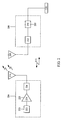
- FIG. 2 shows a simplified schematic diagram of another embodiment 200 of wireless power transfer system 100 described with respect to FIG. 1 .
- Wireless power system 200 can include at least transmitter 204 that, in turn, includes, an oscillator 222, a power amplifier 224 and a filter and matching circuit 226.
- the oscillator is configured to generate a desired frequency, which may be adjusted in response to adjustment signal 223.
- the oscillator signal may be amplified by the power amplifier 224 with an amplification amount responsive to control signal 225.
- the filter and matching circuit 226 may be included to filter out harmonics or other unwanted frequencies and match the impedance of the transmitter 204 to the transmit antenna 214.
- the receiver 208 may include a matching circuit 232 and a rectifier and switching circuit 234 to generate a DC power output to charge a battery 236 as shown in FIG. 3 or power a device coupled to the receiver (not shown).
- the matching circuit 232 may be included to match the impedance of the receiver 208 to the receive antenna 218.
- the receiver 208 and transmitter 204 may communicate on a separate communication channel 113 (e.g., Bluetooth, cellular, WiFi etc).
- antennas used in exemplary embodiments may be configured as a "loop" antenna 350, which may also be referred to herein as a "magnetic" antenna.
- Loop antennas may be configured to include an air core or a physical core such as a ferrite core. Air core loop antennas may be more tolerable to extraneous physical devices placed in the vicinity of the core. Furthermore, an air core loop antenna allows the placement of other components within the core area. Efficient transfer of energy between the transmitter 104 and receiver 208 occurs during matched or nearly matched resonance between the transmitter 204 and the receiver 208. However, even when resonance between the transmitter 204 and receiver 208 are not matched, energy may be transferred at a lower efficiency. Transfer of energy occurs by coupling energy from the near-field of the transmitting antenna to the receiving antenna residing in the neighborhood where this near-field is established rather than propagating the energy from the transmitting antenna into free space.
- the resonant frequency of the loop or magnetic antennas is based on the inductance and capacitance.
- Inductance in a loop antenna is generally simply the inductance created by the loop, whereas, capacitance is generally added to the loop antenna's inductance to create a resonant structure at a desired resonant frequency.
- capacitor 352 and capacitor 354 may be added to the antenna to create a resonant circuit that generates resonant signal 356. Accordingly, for larger diameter loop antennas, the size of capacitance needed to induce resonance decreases as the diameter or inductance of the loop increases. Furthermore, as the diameter of the loop or magnetic antenna increases, the efficient energy transfers area of the near-field increases.
- resonant circuits are possible.
- a capacitor may be placed in parallel between the two terminals of the loop antenna.
- the resonant signal 356 may be an input to the loop antenna 350.
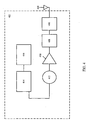
- FIG. 4 is a simplified block diagram of transmit circuitry 402 and associated transmit antenna 404.
- transmit circuitry 402 provides RF power to the transmit antenna 404 by providing an oscillating signal resulting in generation of near-field energy about the transmit antenna 404.
- transmit circuitry 402 may operate at the 13.56 MHz ISM band.
- Transmit circuitry 402 includes a fixed impedance matching circuit 406 for matching the impedance of the transmit circuitry 402 (e.g., 50 ohms) to the transmit antenna 404 and a low pass filter (LPF) 408 configured to reduce harmonic emissions to levels to prevent self-jamming of devices coupled to receivers 208.
- LPF low pass filter
- Transmit circuitry 402 further includes a power amplifier 410 configured to drive an RF signal as determined by an oscillator 412.
- the transmit circuitry may be comprised of discrete devices or circuits, or alternately, may be comprised of an integrated assembly.
- An exemplary RF power output from transmit antenna 404 may be on the order of 2.5 to 8.0 Watts.
- Transmit circuitry 402 further includes a controller 414 for enabling the oscillator 412 during transmit phases (or duty cycles) for specific receivers, for adjusting the frequency of the oscillator, and for adjusting the output power level for implementing a communication protocol for interacting with neighboring devices through their attached receivers.
- the transmit circuitry 402 may further include a load sensing circuit 416 for detecting the presence or absence of active receivers in the vicinity of the near-field generated by transmit antenna 404.
- a load sensing circuit 416 monitors the current flowing to the power amplifier 410, which is affected by the presence or absence of active receivers in the vicinity of the near-field generated by transmit antenna 404. Detection of changes to the loading on the power amplifier 410 are monitored by controller 414 for use in determining whether to enable the oscillator 412 for transmitting energy to communicate with an active receiver.
- Transmit antenna 404 may be implemented as an antenna strip with the thickness, width and metal type selected to keep resistive losses low.
- the transmit antenna 404 can generally be configured for association with a larger structure such as a table, mat, lamp or other less portable configuration. Accordingly, the transmit antenna 404 generally will not need "turns" in order to be of a practical dimension.
- An exemplary implementation of a transmit antenna 404 may be "electrically small” (i.e., fraction of the wavelength) and tuned to resonate at lower usable frequencies by using capacitors to define the resonant frequency.
- Transmit circuitry 402 may gather and track information about the whereabouts and status of receiver devices that may be associated with the transmit circuitry 402.
- the transmitter circuitry 402 may include a presence detector, an enclosed detector, or a combination thereof, connected to the controller 414 (also referred to as a processor herein).
- wireless power can be provided by at least one wireless power source having a circularly polarized source resonator. More specifically, FIG. 5 shows wireless power source 500 arranged to transfer power utilizing a circularly polarized magnetic field in accordance with the described embodiments.
- Wireless power source 500 can include power supply 502.
- power supply 502 can take the form of high frequency, orthogonal in-band power transmitter that can supply high frequency (HF) power to base plate 504.
- Base plate 504 provides HF power to resonators 506 that can take the form of "D" shaped resonators.
- each of D shaped resonators 506 can act as a circular polarized magnetic field source resonator that can convert at least some of the HF power provided to base plate 504 to separate component magnetic fields B 1 and B 2 that can combine with each other to form resulting magnetic field 508.
- the at least two D shaped resonators 506 can be driven by base plate 504 about 180° out of phase with each other such that the resulting component magnetic fields B 1 and B 2 are also 180° out of phase with each other. The combining of the two out of phase component magnetic fields B 1 and B 2 can result in a resulting magnetic field that is circularly polarized.
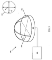
- FIG. 6A shows that a resonant channel can be formed between wireless power supply 500 and peripheral device 602.
- Peripheral device 602 can be configured as a mobile device that can be moved to any position within effective distance d of wireless power supply 500.
- Effective distance d can represent a distance from wireless power supply 500 over which a useful amount of power can be received by peripheral device 602 from wireless power supply 500. Effective distance d can range from a few centimeters to a few meters.
- effective distance d can be affected by many factors in addition to the size and shape of resonators 504 and the size and shape of resonators 604 included in peripheral device 602.
- maximum distance D represents that area around power supply 500 where a minimum pre-determined amount of power P min can be wirelessly received at peripheral device 602 from power supply 500.
- power P min can be set at 20 mW representing the least amount of power that can be transferred to peripheral device 602 in order for peripheral device 602 to operate in a fully operable manner.
- power P min can vary thereby altering effective range D of power supply 500.
- Resulting magnetic field 508 can be formed by combining component magnetic fields B 1 and B 2 generated by resonators 504 in wireless power supply 500.
- peripheral device 602 can take the form of computer mouse 602.
- Computer mouse 602 can include resonators 604 each having a shape factor associated with resonators 506 included in wireless power supply 500.
- resonators 604 can also be "D" shaped. In this way, the interaction of D shaped resonators 604 can be optimized for the most efficient wireless power transmission.
- resulting magnetic field 508 allows computer mouse 602 to maintain any spatial orientation on a supporting surface or in free space and still maintain an essentially constant power transfer between wireless power supply 500 and computer mouse 602 (as shown below).
- FIG. 6B shows cross section of peripheral device 602 along line AA illustrating housing 606 coupled to base portion 608.
- housing 606 can enclose resonators 604 electrically coupled to battery 610 and operational components 612 in base portion 608.
- battery 610 and operational components 612 can receive a relatively constant supply of power from wireless power supply 500 by way of resonators 604.
- battery 610 is not necessary as power can be received wirelessly from wireless power supply 500 thereby obviating the need for any on-board power supply.
- peripheral device 602 in the form of mouse 602 can include resonators 604 that are substantially equal in size and at about right angles to each other. In this way, the geometry of resonators 604 can be tuned to the properties of circularly polarized magnetic field 508. Due to the matching symmetry between circularly polarized magnetic field 508 and resonators 604, power from power supply 500 can be received at or above an acceptable level regardless of the spatial orientation of computer mouse 602 with respect to power supply 500 (and more particularly resonators 504). As further illustrated in FIG. 6D , peripheral device 602 can be rotated about ninety degrees from the orientation shown in FIG. 6C and still maintain an advantageous orientation with respect to resonators 506 in power supply 500 and resonators 604 in computer mouse 602.
- the magnetic field provided by power supply 500 can in fact take on an elliptical shape (a circle being a special case of an ellipse) as illustrated in FIG. 6E .
- resonators 604 in peripheral device 602 can also take on a corresponding elliptical shape thereby optimizing an amount of power transferred from power supply 500 to peripheral device 602 as well as optimizing the power transfer efficiency.
- circularly polarized magnetic field 508 can be "steered" by modifying the orientation of the at least two D shaped magnetic fields generated by D shaped resonators 506 for example, by modifying the orientation of the axes of the elliptical shaped magnetic field.
- the target device (which in this representation takes the form of a computer mouse) can include only a single orientation receiver that although reduces the rate of power transfer that can be achieved from using more than one resonator, but nonetheless may be a suitable solution when available space or size is a significant consideration.
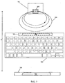
- FIG. 7 illustrates an embodiment whereby peripheral device 602 takes on the form of keyboard 700 within maximum range D of wireless power supply 500.
- FIG. 7 shows a top view of keyboard 700 having wireless power receiver unit 702 incorporated as part of the structure of keyboard 700.
- keyboard 700 can be formed of metal such as aluminum.
- Wireless power receiver unit 702 can include at least one resonator 704.
- resonator 704 can take the form of a D shaped resonator matching resonator 504 in wireless power supply 500. In this way, keyboard 700 can wirelessly receive power by way of circularly polarized magnetic field 508 regardless of the orientation of keyboard 700 with respect to wireless power supply 500.
- wireless power supply 500 can be incorporated in another device, such as computing system 706.
- computing system 706 the actual spatial orientation of keyboard 700 with respect to computing system 706 is quite limited (unlike that of a computer mouse). Therefore, resonator 704 can be limited to a single D shaped resonator that can be fabricated as part of keyboard 700 without significant adverse affect on the ability of keyboard 700 from receiving at least an amount of power sufficient for full operation of keyboard 700.
- ground comb 800 as shown in FIG. 8A can be used to selectively block some magnetic flux and preferentially allow other magnetic flux to pass.
- Ground comb 800 can be formed of magnetically active material in the form of first set of fingers 802 spaced apart to allow at least some magnetic flux B to pass through interstitial spacing.
- at least second set of fingers 804 can be applied across first set of fingers 802 for form apertures 806.
- Apertures 806 are configured to allow only selected portions and amounts of incident magnetic field B inc to pass through as magnetic field B out , the remaining portions of incident magnetic field B inc being blocked as shown in FIG. 8B .
- the resonant frequency of the wireless power supply can be tuned and de-tuned to any frequency.
- the tuning of the resonant frequency can be done dynamically by changing a shape of at least one resonator.
- the changing of the shape of the at least one resonator can be carried out using, for example, a piezoelectric shaping techniques.
- parasitic capacitance can be used to tune/detune a resonator.
- the wireless power transmitter can vary a center resonance frequency in order to compensate for parasitic capacitance.
- FIG. 9 shows a flowchart detailing process 900 for determining a resonant frequency of a magnetic power transfer system in accordance with the described embodiments.
- Process 900 can begin at 902 by providing a magnetic field at a frequency.
- the frequency of the magnetic field can be based at least in part upon the characteristic sizes of the constituents of the magnetic power transfer system.
- the characteristic size of the power resonator as well as any of the receiving resonators can be used to determine the magnetic field frequency.
- the amount of power to be transferred can also affect the frequency as more power may require a higher frequency.
- an indication of an amount of power wirelessly received at a receiver is obtained at 904.
- the indication can be obtained using a communication channel (sometimes referred to as a back channel) using any suitable manner of communication such as WiFiTM, Bluetooth, and so on.
- a determination is made at 906 if the amount of power received is indicative of a maximum power. The determination can be based upon a pre-determined power amount that has been designated as a maximum power for the particular system or the determination can be based upon a comparison of previous indications of received power.
- the frequency is updated at 908 and control is passed back to 902.
- the updating of the frequency can be accomplished in many ways.
- the frequency can be updated by varying the geometry of the resonators.
- the resonant frequency of the wireless power supply can be tuned and de-tuned to any frequency.
- the tuning of the resonant frequency can be done dynamically by changing a shape of at least one resonator.
- the changing of the shape of the at least one resonator can be carried out using, for example, a piezoelectric shaping techniques.
- parasitic capacitance can be used to tune/detune a resonator.
- the wireless power transmitter can vary a center resonance frequency in order to compensate for parasitic capacitance.
- the power received is determined to be maximum, that at 910 the frequency is the resonant frequency and process 900 ends.
- the dynamic tuning can also be used to arbitrate power amongst a plurality of receiving devices. For example, one or more nodes can be tuned in succession followed by a query requesting a confirmation of how much power was received by those devices receiving power at a particular frequency. In this way, resonant modes not equal to the original center frequency can be determined. Hence, maximum power can be transferred at one of the determined resonant frequency. In this way, the most efficient power transfer can occur at the original center frequency but, however, the most amount of power can be transferred at one of the other resonant mode frequencies. Resonant modes can be determined by nulling out a particular receiving device, using for example, a backchannel.
- the wireless power transmitter can look for a change in impedance when the wireless power transmitter is broadcasting on a resonant mode. In this way, by sweeping through a particular frequency band, a number of resonant modes can be determined. In some cases, resonators can be coupled together to form chained re-resonators.
- FIG. 10 shows representative virtual charging area 1000 in accordance with the described embodiments.
- Virtual charging area 1000 provides region R of charging for suitably configured devices placed within the region R.
- NFMR power supply can be placed in central unit such as desktop computer. In this way, the desktop computer can provide the NFMR power supply with computing resources.
- the near field magnetic resonance (NFMR) power supply can include high Q circuit that relies upon near field magnetic coupling by way of a resonance channel formed between resonances of the power source and sink to transfer power.
- the NFMR power supply can be a standalone unit such as, for example, included in a desk top computer, laptop computer, tablet computer, and so on.
- the NFMR power supply can take the form of a portable type unit such as a dongle that can be connected to a legacy device such as a desktop computer thereby providing the ability to retrofit devices.
- housing or a portion of a housing used to enclose the NFMR power source can act to extend a useful range of the NFMR power supply.
- peripheral devices can be powered directly from the NFMR power supply.
- the peripheral devices when tuned to the appropriate frequency can receive power wirelessly from the NFMR power supply.
- the appropriately tuned peripheral device can be considered to be part of a resonance circuit that can include the NFMR power supply and any other peripheral devices so tuned.
- each device has associated with it a corresponding load that can be sensed by the NFMR power supply.
- the resonance circuit can have a characteristic load that can change by the addition or deletion of devices from the resonance circuit.
- any change in the characteristic load factor of the resonance circuit can convey information that can be used by the NFMR power supply to control the various devices in the resonance circuit by, for example, distributing power, and so on.
- certain of the peripheral devices can be configured to include a re-resonator circuit that can receive power directly from the NFMR power supply. Such devices can also transfer a portion of the power received to other of the peripheral devices.
- Virtual charging area 1000 includes central unit 1002 (desktop computer) that can include the NFMR power supply, keyboard 1004, mouse 1006, and portable media player 1008.
- keyboard 1004 can be configured to receive power directly from the NFMR power supply included in desktop computer 1002 as can mouse 1006 and portable media player 1008.
- desktop computer 1002 can provide power directly to mouse 1006, for example, due to any number of factors. Such factors can include, for example, the addition of other devices into region R that require power from the NFMR power supply, obstacles interfering with the direct power channel formed between the NFMR and mouse 1006, and so on.
- keyboard 1004 can act as a re-resonator such that a portion of the power delivered to keyboard 1004 from the NFMR power supply can be passed on by way of a re-resonator transmission unit (not shown) in keyboard 1004. In this way, any power loss experienced by mouse 1006 can be ameliorated by the power received from keyboard 1004.
- This arrangement can be transitory or can last for as long as mouse 1006 is not able to receive adequate power directly from the NFMR power supply.
- the locating of portable media player 1008 within region R can reduce the amount of power available to keyboard 1004 and mouse 1006. In this case, if a battery in keyboard 1006 is fully charged (or additional charge is not necessary) then keyboard 1006 can decouple a charging circuit while still maintaining a re-resonator circuit providing power to mouse 1006.
- conductive material 1012 can be used as a waveguide and/or magnetic flux concentrator.
- metallic surfaces and structures can be used to guide/concentrate high frequency resonances by, for example, boosting coupling coefficient k.
- Conductive surfaces (such as table tops, computer housing, etc.) can be used a flux concentrators as well as metal housings.
- the various aspects, embodiments, implementations or features of the described embodiments can be used separately or in any combination.
- Various aspects of the described embodiments can be implemented by software, hardware or a combination of hardware and software.
- the described embodiments can also be embodied as computer readable code on a non-transitory computer readable medium.
- the computer readable medium is defined as any data storage device that can store data which can thereafter be read by a computer system. Examples of the computer readable medium include read-only memory, random-access memory, CD-ROMs, DVDs, magnetic tape, and optical data storage devices.
- the computer readable medium can also be distributed over network-coupled computer systems so that the computer readable code is stored and executed in a distributed fashion.
Landscapes
- Engineering & Computer Science (AREA)
- Computer Networks & Wireless Communication (AREA)
- Power Engineering (AREA)
- Physics & Mathematics (AREA)
- Signal Processing (AREA)
- Condensed Matter Physics & Semiconductors (AREA)
- General Physics & Mathematics (AREA)
- Electromagnetism (AREA)
- Charge And Discharge Circuits For Batteries Or The Like (AREA)
- Near-Field Transmission Systems (AREA)
Applications Claiming Priority (2)
| Application Number | Priority Date | Filing Date | Title |
|---|---|---|---|
| US41670110P | 2010-11-23 | 2010-11-23 | |
| PCT/US2011/061384 WO2012071268A2 (en) | 2010-11-23 | 2011-11-18 | Wireless power utilization in a local computing environment |
Publications (2)
| Publication Number | Publication Date |
|---|---|
| EP2643916A2 EP2643916A2 (en) | 2013-10-02 |
| EP2643916B1 true EP2643916B1 (en) | 2016-03-16 |
Family
ID=45406839
Family Applications (1)
| Application Number | Title | Priority Date | Filing Date |
|---|---|---|---|
| EP11801889.4A Not-in-force EP2643916B1 (en) | 2010-11-23 | 2011-11-18 | Wireless power utilization in a local computing environment |
Country Status (7)
| Country | Link |
|---|---|
| US (3) | US8598747B2 (zh) |
| EP (1) | EP2643916B1 (zh) |
| KR (3) | KR101480658B1 (zh) |
| CN (4) | CN202565038U (zh) |
| AU (1) | AU2011332142B2 (zh) |
| TW (1) | TWI461720B (zh) |
| WO (1) | WO2012071268A2 (zh) |
Families Citing this family (38)
| Publication number | Priority date | Publication date | Assignee | Title |
|---|---|---|---|---|
| US8400017B2 (en) * | 2008-09-27 | 2013-03-19 | Witricity Corporation | Wireless energy transfer for computer peripheral applications |
| KR101393758B1 (ko) * | 2009-11-17 | 2014-05-12 | 애플 인크. | 로컬 컴퓨팅 환경에서의 무선 전력 이용 |
| US8598747B2 (en) * | 2010-11-23 | 2013-12-03 | Apple Inc. | Wireless power utilization in a local computing environment |
| JP5854640B2 (ja) * | 2011-05-25 | 2016-02-09 | キヤノン株式会社 | 電子機器、受電方法及びプログラム |
| WO2012166127A1 (en) | 2011-05-31 | 2012-12-06 | Apple Inc. | Small form factor wireless power unit |
| BR112013031018A2 (pt) * | 2011-06-03 | 2016-11-29 | Toyota Motor Co Ltd | dispositivo de recepção de energia sem contato e veículo incluindo o mesmo, dispositivo de transmissão de energia sem contato e sistema de transferência de energia sem contato |
| ITTO20120477A1 (it) * | 2012-05-31 | 2013-12-01 | St Microelectronics Srl | Rete di dispositivi elettronici fissati ad un supporto flessibile e relativo metodo di comunicazione |
| US10787085B2 (en) * | 2012-12-11 | 2020-09-29 | Toyota Jidosha Kabushiki Kaisha | Vehicle, power transmission device, and power feeding system |
| JP6391911B2 (ja) | 2013-01-23 | 2018-09-19 | キヤノンメディカルシステムズ株式会社 | 磁気共鳴イメージング装置、及び、rfコイル装置 |
| US9627915B2 (en) * | 2013-03-15 | 2017-04-18 | Flextronics Ap, Llc | Sweep frequency mode for multiple magnetic resonant power transmission |
| WO2014148843A1 (en) | 2013-03-21 | 2014-09-25 | Samsung Electronics Co., Ltd. | Wireless power transmitting unit, wireless power receiving unit, and control methods |
| US9491705B2 (en) | 2013-07-31 | 2016-11-08 | Jonathan W. Skipper | Radio frequency method for recharging a wireless telephone |
| DE102013216753A1 (de) | 2013-08-23 | 2015-02-26 | Novero Dabendorf Gmbh | Vorrichtung und Verfahren zur kombinierten Signalübertragung oder zur kombinierten Signal- und Energieübertragung |
| US9325184B2 (en) * | 2013-12-19 | 2016-04-26 | Qualcomm Technologies International, Ltd. | Apparatus for wirelessly charging a rechargeable battery |
| KR102257688B1 (ko) * | 2014-07-23 | 2021-05-31 | 엘지이노텍 주식회사 | 무선 충전 및 근거리 통신 겸용 송신 장치 |
| US9635222B2 (en) | 2014-08-03 | 2017-04-25 | PogoTec, Inc. | Wearable camera systems and apparatus for aligning an eyewear camera |
| RU2017106629A (ru) | 2014-08-03 | 2018-09-04 | Поготек, Инк. | Система носимых камер и устройств, а также способ прикрепления систем камер или других электронных устройств к носимым изделиям |
| KR20160051497A (ko) | 2014-11-03 | 2016-05-11 | 주식회사 한림포스텍 | 무선 전력 전송 네트워크의 전력 전송 커버리지 제어 장치 및 방법 |
| BR112017013618A2 (pt) | 2014-12-23 | 2018-06-19 | Pogotec Inc | câmeras, sistemas e métodos para receber energia sem fio |
| US10481417B2 (en) | 2015-06-10 | 2019-11-19 | PogoTec, Inc. | Magnetic attachment mechanism for electronic wearable device |
| JP2018521345A (ja) | 2015-06-10 | 2018-08-02 | ポゴテック インクPogoTec, Inc. | ウェアラブル電子機器用の磁気的トラックを備えたアイウェア |
| US10601099B2 (en) * | 2015-09-10 | 2020-03-24 | Cpg Technologies, Llc | Mobile guided surface waveguide probes and receivers |
| US10438732B2 (en) * | 2015-09-16 | 2019-10-08 | Qorvo Us, Inc. | Monolithic wideband trifilar transformer |
| US10341787B2 (en) | 2015-10-29 | 2019-07-02 | PogoTec, Inc. | Hearing aid adapted for wireless power reception |
| US9837832B2 (en) * | 2015-12-29 | 2017-12-05 | Motorola Solutions, Inc. | Wireless power transfer device and method |
| KR102492190B1 (ko) | 2016-01-11 | 2023-01-27 | 삼성전자주식회사 | 무선 전력 전송 장치, 무선 충전 시스템 및 이들의 제어 방법 |
| US11558538B2 (en) | 2016-03-18 | 2023-01-17 | Opkix, Inc. | Portable camera system |
| EP3482474A4 (en) | 2016-06-20 | 2020-07-29 | Ami Research&development, LLC | LOW FREQUENCY RECTENNA SYSTEM FOR WIRELESS CHARGING |
| US10530175B2 (en) * | 2016-08-09 | 2020-01-07 | Taiwan Semiconductor Manufacturing Company, Ltd. | Hexagonal semiconductor package structure |
| EP3539285A4 (en) | 2016-11-08 | 2020-09-02 | Pogotec, Inc. | PORTABLE ELECTRONIC DEVICE INTELLIGENT BOX |
| KR102328712B1 (ko) | 2017-03-03 | 2021-11-22 | 삼성전자주식회사 | 무선 전력 전송을 위한 전송 장치 및 이의 제어 방법 |
| RU2658332C1 (ru) * | 2017-08-04 | 2018-06-20 | Самсунг Электроникс Ко., Лтд. | Система беспроводной передачи мощности для среды с многолучевым распространением |
| KR20190097659A (ko) | 2018-02-13 | 2019-08-21 | 강동연 | 스마트 폰 무선전력충전 시스템 |
| KR102433881B1 (ko) | 2018-02-14 | 2022-08-19 | 삼성전자주식회사 | 전자 장치 및 그 제어 방법 |
| KR20190100665A (ko) | 2018-02-21 | 2019-08-29 | 강동연 | 스마트 폰 무선전력충전 시스템 |
| US11300857B2 (en) | 2018-11-13 | 2022-04-12 | Opkix, Inc. | Wearable mounts for portable camera |
| WO2021149283A1 (ja) * | 2020-07-27 | 2021-07-29 | 三菱電機エンジニアリング株式会社 | 無線電力伝送システム及び無線電力受信装置 |
| TWI774058B (zh) * | 2020-09-11 | 2022-08-11 | 寶德科技股份有限公司 | 鍵盤裝置以及周邊裝置組合 |
Family Cites Families (20)
| Publication number | Priority date | Publication date | Assignee | Title |
|---|---|---|---|---|
| JPH09204950A (ja) * | 1996-01-26 | 1997-08-05 | Matsushita Electric Works Ltd | マルチメディア用配線器具 |
| JP2006314181A (ja) | 2005-05-09 | 2006-11-16 | Sony Corp | 非接触充電装置及び非接触充電システム並びに非接触充電方法 |
| CN2919568Y (zh) * | 2006-01-26 | 2007-07-04 | 友劲科技股份有限公司 | 适用于无线网络装置上的平板天线 |
| CA2640259A1 (en) * | 2006-01-31 | 2007-08-09 | Powercast Corporation | Power transmission network and method |
| EP2027705A2 (en) * | 2006-06-14 | 2009-02-25 | Powercast Corporation | Wireless power transmission |
| WO2009145747A1 (en) * | 2007-05-24 | 2009-12-03 | Face Bradbury R | Lighting fixture with low voltage transformer & self-powered switching system |
| KR101473600B1 (ko) | 2007-09-17 | 2014-12-16 | 퀄컴 인코포레이티드 | 무선 전력 자기 공진기에서의 고효율 및 고전력 전송 |
| WO2009039113A1 (en) | 2007-09-17 | 2009-03-26 | Nigel Power, Llc | Transmitters and receivers for wireless energy transfer |
| US8855554B2 (en) * | 2008-03-05 | 2014-10-07 | Qualcomm Incorporated | Packaging and details of a wireless power device |
| US8629576B2 (en) | 2008-03-28 | 2014-01-14 | Qualcomm Incorporated | Tuning and gain control in electro-magnetic power systems |
| WO2009122355A2 (en) | 2008-04-03 | 2009-10-08 | Philips Intellectual Property & Standards Gmbh | Wireless power transmission system |
| US20100038970A1 (en) * | 2008-04-21 | 2010-02-18 | Nigel Power, Llc | Short Range Efficient Wireless Power Transfer |
| JP4544339B2 (ja) * | 2008-04-28 | 2010-09-15 | ソニー株式会社 | 送電装置、送電方法、プログラム、および電力伝送システム |
| TW200950257A (en) | 2008-05-20 | 2009-12-01 | Darfon Electronics Corp | Wireless charging module and electronic apparatus |
| JP5353376B2 (ja) * | 2009-03-31 | 2013-11-27 | 富士通株式会社 | 無線電力装置、無線電力受信方法 |
| US8970180B2 (en) * | 2009-04-07 | 2015-03-03 | Qualcomm Incorporated | Wireless power transmission scheduling |
| US8853995B2 (en) | 2009-06-12 | 2014-10-07 | Qualcomm Incorporated | Devices for conveying wireless power and methods of operation thereof |
| TWI451458B (zh) * | 2009-08-25 | 2014-09-01 | Access Business Group Int Llc | 磁通量集中器及製造一磁通量集中器的方法 |
| JP5338598B2 (ja) * | 2009-09-29 | 2013-11-13 | 富士通株式会社 | 水晶発振器製造方法、及び水晶発振器製造装置 |
| US8598747B2 (en) * | 2010-11-23 | 2013-12-03 | Apple Inc. | Wireless power utilization in a local computing environment |
-
2011
- 2011-11-18 US US13/989,047 patent/US8598747B2/en active Active
- 2011-11-18 KR KR20137016176A patent/KR101480658B1/ko active IP Right Grant
- 2011-11-18 EP EP11801889.4A patent/EP2643916B1/en not_active Not-in-force
- 2011-11-18 KR KR1020147020609A patent/KR20140098262A/ko not_active Application Discontinuation
- 2011-11-18 KR KR1020177037334A patent/KR20180004296A/ko not_active Application Discontinuation
- 2011-11-18 AU AU2011332142A patent/AU2011332142B2/en not_active Ceased
- 2011-11-18 WO PCT/US2011/061384 patent/WO2012071268A2/en active Application Filing
- 2011-11-21 TW TW100142550A patent/TWI461720B/zh not_active IP Right Cessation
- 2011-11-23 CN CN2011205799277U patent/CN202565038U/zh not_active Expired - Lifetime
- 2011-11-23 CN CN201220523878XU patent/CN202997711U/zh not_active Expired - Lifetime
- 2011-11-23 CN CN201110462933.9A patent/CN102570629B/zh not_active Expired - Fee Related
- 2011-11-23 CN CN201510551710.8A patent/CN105162264A/zh active Pending
-
2013
- 2013-11-01 US US14/070,188 patent/US20140054974A1/en not_active Abandoned
-
2017
- 2017-05-04 US US15/587,293 patent/US20170366045A1/en not_active Abandoned
Also Published As
| Publication number | Publication date |
|---|---|
| KR20140098262A (ko) | 2014-08-07 |
| US20140054974A1 (en) | 2014-02-27 |
| CN102570629B (zh) | 2015-07-22 |
| CN202565038U (zh) | 2012-11-28 |
| KR20130099181A (ko) | 2013-09-05 |
| US20170366045A1 (en) | 2017-12-21 |
| KR101480658B1 (ko) | 2015-01-09 |
| CN102570629A (zh) | 2012-07-11 |
| WO2012071268A2 (en) | 2012-05-31 |
| EP2643916A2 (en) | 2013-10-02 |
| KR20180004296A (ko) | 2018-01-10 |
| CN105162264A (zh) | 2015-12-16 |
| AU2011332142B2 (en) | 2014-12-11 |
| US20130241308A1 (en) | 2013-09-19 |
| CN202997711U (zh) | 2013-06-12 |
| US8598747B2 (en) | 2013-12-03 |
| AU2011332142A1 (en) | 2013-05-09 |
| TW201241462A (en) | 2012-10-16 |
| WO2012071268A3 (en) | 2013-04-25 |
| TWI461720B (zh) | 2014-11-21 |
Similar Documents
| Publication | Publication Date | Title |
|---|---|---|
| EP2643916B1 (en) | Wireless power utilization in a local computing environment | |
| US9013141B2 (en) | Parasitic devices for wireless power transfer | |
| JP6030305B2 (ja) | 可搬エンクロージャ用の無線電力伝達 | |
| US10523276B2 (en) | Wireless power receiver with multiple receiver coils | |
| US20160013661A1 (en) | Resonators for wireless power transfer systems | |
| US20110198937A1 (en) | Impedance neutral wireless power receivers | |
| EP2502325B1 (en) | Forward link signaling within a wireless power system | |
| US20120311356A1 (en) | Automatically tuning a transmitter to a resonance frequency of a receiver | |
| US20130300205A1 (en) | Method and apparatus for 3d orientation-free wireless power transfer | |
| US20130187598A1 (en) | Apparatus and method for transmitting wireless power by using resonant coupling and system for the same | |
| US20110062916A1 (en) | Movable magnetically resonant antenna for wireless charging | |
| KR101962747B1 (ko) | 무선 전력 전송 시스템의 누설 자기장 차폐 장치 및 방법 | |
| US20110217926A1 (en) | Reverse link signaling via impedance modulation | |
| KR20110134971A (ko) | 무선 전력 전송 시스템에서 부 송신기를 이용한 송신전력 빔포밍 장치 및 방법 |
Legal Events
| Date | Code | Title | Description |
|---|---|---|---|
| PUAI | Public reference made under article 153(3) epc to a published international application that has entered the european phase |
Free format text: ORIGINAL CODE: 0009012 |
|
| 17P | Request for examination filed |
Effective date: 20130621 |
|
| AK | Designated contracting states |
Kind code of ref document: A2 Designated state(s): AL AT BE BG CH CY CZ DE DK EE ES FI FR GB GR HR HU IE IS IT LI LT LU LV MC MK MT NL NO PL PT RO RS SE SI SK SM TR |
|
| DAX | Request for extension of the european patent (deleted) | ||
| 17Q | First examination report despatched |
Effective date: 20140620 |
|
| GRAP | Despatch of communication of intention to grant a patent |
Free format text: ORIGINAL CODE: EPIDOSNIGR1 |
|
| INTG | Intention to grant announced |
Effective date: 20150128 |
|
| GRAP | Despatch of communication of intention to grant a patent |
Free format text: ORIGINAL CODE: EPIDOSNIGR1 |
|
| INTG | Intention to grant announced |
Effective date: 20150902 |
|
| GRAS | Grant fee paid |
Free format text: ORIGINAL CODE: EPIDOSNIGR3 |
|
| GRAA | (expected) grant |
Free format text: ORIGINAL CODE: 0009210 |
|
| AK | Designated contracting states |
Kind code of ref document: B1 Designated state(s): AL AT BE BG CH CY CZ DE DK EE ES FI FR GB GR HR HU IE IS IT LI LT LU LV MC MK MT NL NO PL PT RO RS SE SI SK SM TR |
|
| REG | Reference to a national code |
Ref country code: GB Ref legal event code: FG4D |
|
| REG | Reference to a national code |
Ref country code: CH Ref legal event code: EP |
|
| REG | Reference to a national code |
Ref country code: IE Ref legal event code: FG4D |
|
| REG | Reference to a national code |
Ref country code: AT Ref legal event code: REF Ref document number: 781966 Country of ref document: AT Kind code of ref document: T Effective date: 20160415 |
|
| REG | Reference to a national code |
Ref country code: DE Ref legal event code: R096 Ref document number: 602011024134 Country of ref document: DE |
|
| REG | Reference to a national code |
Ref country code: NL Ref legal event code: MP Effective date: 20160316 |
|
| REG | Reference to a national code |
Ref country code: LT Ref legal event code: MG4D |
|
| PG25 | Lapsed in a contracting state [announced via postgrant information from national office to epo] |
Ref country code: FI Free format text: LAPSE BECAUSE OF FAILURE TO SUBMIT A TRANSLATION OF THE DESCRIPTION OR TO PAY THE FEE WITHIN THE PRESCRIBED TIME-LIMIT Effective date: 20160316 Ref country code: GR Free format text: LAPSE BECAUSE OF FAILURE TO SUBMIT A TRANSLATION OF THE DESCRIPTION OR TO PAY THE FEE WITHIN THE PRESCRIBED TIME-LIMIT Effective date: 20160617 Ref country code: HR Free format text: LAPSE BECAUSE OF FAILURE TO SUBMIT A TRANSLATION OF THE DESCRIPTION OR TO PAY THE FEE WITHIN THE PRESCRIBED TIME-LIMIT Effective date: 20160316 Ref country code: NO Free format text: LAPSE BECAUSE OF FAILURE TO SUBMIT A TRANSLATION OF THE DESCRIPTION OR TO PAY THE FEE WITHIN THE PRESCRIBED TIME-LIMIT Effective date: 20160616 |
|
| REG | Reference to a national code |
Ref country code: AT Ref legal event code: MK05 Ref document number: 781966 Country of ref document: AT Kind code of ref document: T Effective date: 20160316 |
|
| PG25 | Lapsed in a contracting state [announced via postgrant information from national office to epo] |
Ref country code: LV Free format text: LAPSE BECAUSE OF FAILURE TO SUBMIT A TRANSLATION OF THE DESCRIPTION OR TO PAY THE FEE WITHIN THE PRESCRIBED TIME-LIMIT Effective date: 20160316 Ref country code: NL Free format text: LAPSE BECAUSE OF FAILURE TO SUBMIT A TRANSLATION OF THE DESCRIPTION OR TO PAY THE FEE WITHIN THE PRESCRIBED TIME-LIMIT Effective date: 20160316 Ref country code: SE Free format text: LAPSE BECAUSE OF FAILURE TO SUBMIT A TRANSLATION OF THE DESCRIPTION OR TO PAY THE FEE WITHIN THE PRESCRIBED TIME-LIMIT Effective date: 20160316 Ref country code: LT Free format text: LAPSE BECAUSE OF FAILURE TO SUBMIT A TRANSLATION OF THE DESCRIPTION OR TO PAY THE FEE WITHIN THE PRESCRIBED TIME-LIMIT Effective date: 20160316 Ref country code: RS Free format text: LAPSE BECAUSE OF FAILURE TO SUBMIT A TRANSLATION OF THE DESCRIPTION OR TO PAY THE FEE WITHIN THE PRESCRIBED TIME-LIMIT Effective date: 20160316 |
|
| PG25 | Lapsed in a contracting state [announced via postgrant information from national office to epo] |
Ref country code: IS Free format text: LAPSE BECAUSE OF FAILURE TO SUBMIT A TRANSLATION OF THE DESCRIPTION OR TO PAY THE FEE WITHIN THE PRESCRIBED TIME-LIMIT Effective date: 20160716 Ref country code: EE Free format text: LAPSE BECAUSE OF FAILURE TO SUBMIT A TRANSLATION OF THE DESCRIPTION OR TO PAY THE FEE WITHIN THE PRESCRIBED TIME-LIMIT Effective date: 20160316 Ref country code: PL Free format text: LAPSE BECAUSE OF FAILURE TO SUBMIT A TRANSLATION OF THE DESCRIPTION OR TO PAY THE FEE WITHIN THE PRESCRIBED TIME-LIMIT Effective date: 20160316 |
|
| PG25 | Lapsed in a contracting state [announced via postgrant information from national office to epo] |
Ref country code: SK Free format text: LAPSE BECAUSE OF FAILURE TO SUBMIT A TRANSLATION OF THE DESCRIPTION OR TO PAY THE FEE WITHIN THE PRESCRIBED TIME-LIMIT Effective date: 20160316 Ref country code: SM Free format text: LAPSE BECAUSE OF FAILURE TO SUBMIT A TRANSLATION OF THE DESCRIPTION OR TO PAY THE FEE WITHIN THE PRESCRIBED TIME-LIMIT Effective date: 20160316 Ref country code: AT Free format text: LAPSE BECAUSE OF FAILURE TO SUBMIT A TRANSLATION OF THE DESCRIPTION OR TO PAY THE FEE WITHIN THE PRESCRIBED TIME-LIMIT Effective date: 20160316 Ref country code: ES Free format text: LAPSE BECAUSE OF FAILURE TO SUBMIT A TRANSLATION OF THE DESCRIPTION OR TO PAY THE FEE WITHIN THE PRESCRIBED TIME-LIMIT Effective date: 20160316 Ref country code: RO Free format text: LAPSE BECAUSE OF FAILURE TO SUBMIT A TRANSLATION OF THE DESCRIPTION OR TO PAY THE FEE WITHIN THE PRESCRIBED TIME-LIMIT Effective date: 20160316 Ref country code: PT Free format text: LAPSE BECAUSE OF FAILURE TO SUBMIT A TRANSLATION OF THE DESCRIPTION OR TO PAY THE FEE WITHIN THE PRESCRIBED TIME-LIMIT Effective date: 20160718 Ref country code: CZ Free format text: LAPSE BECAUSE OF FAILURE TO SUBMIT A TRANSLATION OF THE DESCRIPTION OR TO PAY THE FEE WITHIN THE PRESCRIBED TIME-LIMIT Effective date: 20160316 |
|
| REG | Reference to a national code |
Ref country code: DE Ref legal event code: R097 Ref document number: 602011024134 Country of ref document: DE |
|
| PG25 | Lapsed in a contracting state [announced via postgrant information from national office to epo] |
Ref country code: IT Free format text: LAPSE BECAUSE OF FAILURE TO SUBMIT A TRANSLATION OF THE DESCRIPTION OR TO PAY THE FEE WITHIN THE PRESCRIBED TIME-LIMIT Effective date: 20160316 Ref country code: BE Free format text: LAPSE BECAUSE OF FAILURE TO SUBMIT A TRANSLATION OF THE DESCRIPTION OR TO PAY THE FEE WITHIN THE PRESCRIBED TIME-LIMIT Effective date: 20160316 |
|
| PLBE | No opposition filed within time limit |
Free format text: ORIGINAL CODE: 0009261 |
|
| STAA | Information on the status of an ep patent application or granted ep patent |
Free format text: STATUS: NO OPPOSITION FILED WITHIN TIME LIMIT |
|
| PG25 | Lapsed in a contracting state [announced via postgrant information from national office to epo] |
Ref country code: DK Free format text: LAPSE BECAUSE OF FAILURE TO SUBMIT A TRANSLATION OF THE DESCRIPTION OR TO PAY THE FEE WITHIN THE PRESCRIBED TIME-LIMIT Effective date: 20160316 |
|
| 26N | No opposition filed |
Effective date: 20161219 |
|
| PG25 | Lapsed in a contracting state [announced via postgrant information from national office to epo] |
Ref country code: BG Free format text: LAPSE BECAUSE OF FAILURE TO SUBMIT A TRANSLATION OF THE DESCRIPTION OR TO PAY THE FEE WITHIN THE PRESCRIBED TIME-LIMIT Effective date: 20160616 |
|
| PG25 | Lapsed in a contracting state [announced via postgrant information from national office to epo] |
Ref country code: SI Free format text: LAPSE BECAUSE OF FAILURE TO SUBMIT A TRANSLATION OF THE DESCRIPTION OR TO PAY THE FEE WITHIN THE PRESCRIBED TIME-LIMIT Effective date: 20160316 |
|
| REG | Reference to a national code |
Ref country code: CH Ref legal event code: PL |
|
| PG25 | Lapsed in a contracting state [announced via postgrant information from national office to epo] |
Ref country code: CH Free format text: LAPSE BECAUSE OF NON-PAYMENT OF DUE FEES Effective date: 20161130 Ref country code: LI Free format text: LAPSE BECAUSE OF NON-PAYMENT OF DUE FEES Effective date: 20161130 |
|
| REG | Reference to a national code |
Ref country code: IE Ref legal event code: MM4A |
|
| REG | Reference to a national code |
Ref country code: FR Ref legal event code: ST Effective date: 20170731 |
|
| PG25 | Lapsed in a contracting state [announced via postgrant information from national office to epo] |
Ref country code: LU Free format text: LAPSE BECAUSE OF NON-PAYMENT OF DUE FEES Effective date: 20161130 |
|
| PG25 | Lapsed in a contracting state [announced via postgrant information from national office to epo] |
Ref country code: FR Free format text: LAPSE BECAUSE OF NON-PAYMENT OF DUE FEES Effective date: 20161130 |
|
| PG25 | Lapsed in a contracting state [announced via postgrant information from national office to epo] |
Ref country code: IE Free format text: LAPSE BECAUSE OF NON-PAYMENT OF DUE FEES Effective date: 20161118 |
|
| PG25 | Lapsed in a contracting state [announced via postgrant information from national office to epo] |
Ref country code: HU Free format text: LAPSE BECAUSE OF FAILURE TO SUBMIT A TRANSLATION OF THE DESCRIPTION OR TO PAY THE FEE WITHIN THE PRESCRIBED TIME-LIMIT; INVALID AB INITIO Effective date: 20111118 Ref country code: CY Free format text: LAPSE BECAUSE OF FAILURE TO SUBMIT A TRANSLATION OF THE DESCRIPTION OR TO PAY THE FEE WITHIN THE PRESCRIBED TIME-LIMIT Effective date: 20160316 |
|
| PG25 | Lapsed in a contracting state [announced via postgrant information from national office to epo] |
Ref country code: MK Free format text: LAPSE BECAUSE OF FAILURE TO SUBMIT A TRANSLATION OF THE DESCRIPTION OR TO PAY THE FEE WITHIN THE PRESCRIBED TIME-LIMIT Effective date: 20160316 Ref country code: MC Free format text: LAPSE BECAUSE OF FAILURE TO SUBMIT A TRANSLATION OF THE DESCRIPTION OR TO PAY THE FEE WITHIN THE PRESCRIBED TIME-LIMIT Effective date: 20160316 |
|
| PG25 | Lapsed in a contracting state [announced via postgrant information from national office to epo] |
Ref country code: MT Free format text: LAPSE BECAUSE OF NON-PAYMENT OF DUE FEES Effective date: 20161118 |
|
| PG25 | Lapsed in a contracting state [announced via postgrant information from national office to epo] |
Ref country code: TR Free format text: LAPSE BECAUSE OF FAILURE TO SUBMIT A TRANSLATION OF THE DESCRIPTION OR TO PAY THE FEE WITHIN THE PRESCRIBED TIME-LIMIT Effective date: 20160316 Ref country code: AL Free format text: LAPSE BECAUSE OF FAILURE TO SUBMIT A TRANSLATION OF THE DESCRIPTION OR TO PAY THE FEE WITHIN THE PRESCRIBED TIME-LIMIT Effective date: 20160316 |
|
| PGFP | Annual fee paid to national office [announced via postgrant information from national office to epo] |
Ref country code: GB Payment date: 20201111 Year of fee payment: 10 |
|
| PGFP | Annual fee paid to national office [announced via postgrant information from national office to epo] |
Ref country code: DE Payment date: 20210923 Year of fee payment: 11 |
|
| GBPC | Gb: european patent ceased through non-payment of renewal fee |
Effective date: 20211118 |
|
| PG25 | Lapsed in a contracting state [announced via postgrant information from national office to epo] |
Ref country code: GB Free format text: LAPSE BECAUSE OF NON-PAYMENT OF DUE FEES Effective date: 20211118 |
|
| REG | Reference to a national code |
Ref country code: DE Ref legal event code: R119 Ref document number: 602011024134 Country of ref document: DE |
|
| PG25 | Lapsed in a contracting state [announced via postgrant information from national office to epo] |
Ref country code: DE Free format text: LAPSE BECAUSE OF NON-PAYMENT OF DUE FEES Effective date: 20230601 |