EP2643815B1 - Forward projection apparatus - Google Patents
Forward projection apparatus Download PDFInfo
- Publication number
- EP2643815B1 EP2643815B1 EP11799324.6A EP11799324A EP2643815B1 EP 2643815 B1 EP2643815 B1 EP 2643815B1 EP 11799324 A EP11799324 A EP 11799324A EP 2643815 B1 EP2643815 B1 EP 2643815B1
- Authority
- EP
- European Patent Office
- Prior art keywords
- rays
- ray
- image
- forward projection
- kernel
- Prior art date
- Legal status (The legal status is an assumption and is not a legal conclusion. Google has not performed a legal analysis and makes no representation as to the accuracy of the status listed.)
- Active
Links
- 238000001514 detection method Methods 0.000 claims description 81
- 230000005855 radiation Effects 0.000 claims description 50
- 238000003384 imaging method Methods 0.000 claims description 12
- 238000000034 method Methods 0.000 claims description 12
- 230000007704 transition Effects 0.000 claims description 12
- 238000004590 computer program Methods 0.000 claims description 7
- 238000002591 computed tomography Methods 0.000 description 5
- 230000003247 decreasing effect Effects 0.000 description 5
- 230000007423 decrease Effects 0.000 description 2
- 230000001419 dependent effect Effects 0.000 description 2
- 230000000694 effects Effects 0.000 description 2
- 238000005070 sampling Methods 0.000 description 2
- 241001465754 Metazoa Species 0.000 description 1
- 230000005540 biological transmission Effects 0.000 description 1
- 230000000747 cardiac effect Effects 0.000 description 1
- 238000002059 diagnostic imaging Methods 0.000 description 1
- 238000003325 tomography Methods 0.000 description 1
- 238000005303 weighing Methods 0.000 description 1
Images


Classifications
-
- G—PHYSICS
- G06—COMPUTING; CALCULATING OR COUNTING
- G06T—IMAGE DATA PROCESSING OR GENERATION, IN GENERAL
- G06T11/00—2D [Two Dimensional] image generation
- G06T11/003—Reconstruction from projections, e.g. tomography
- G06T11/005—Specific pre-processing for tomographic reconstruction, e.g. calibration, source positioning, rebinning, scatter correction, retrospective gating
-
- G—PHYSICS
- G06—COMPUTING; CALCULATING OR COUNTING
- G06T—IMAGE DATA PROCESSING OR GENERATION, IN GENERAL
- G06T11/00—2D [Two Dimensional] image generation
- G06T11/003—Reconstruction from projections, e.g. tomography
- G06T11/008—Specific post-processing after tomographic reconstruction, e.g. voxelisation, metal artifact correction
-
- G—PHYSICS
- G06—COMPUTING; CALCULATING OR COUNTING
- G06T—IMAGE DATA PROCESSING OR GENERATION, IN GENERAL
- G06T2211/00—Image generation
- G06T2211/40—Computed tomography
- G06T2211/424—Iterative
Definitions
- the invention relates to a forward projection apparatus, a forward projection method and a computer program for performing a forward projection through an image.
- the invention relates further to a reconstruction apparatus for iteratively reconstructing an image of a region of interest, which comprises the forward projection apparatus, and an imaging apparatus for generating an image of a region of interest, which comprises an acquisition unit for acquiring projection data and the reconstruction apparatus.
- US 2010/0119034 A1 discloses an apparatus comprising an x-ray source, an x-ray detector having channels and segments, and a signal processing unit connected to receive data collected by the x-ray detector.
- the signal processing unit is configured to determine a channel position on the x-ray detector located on a linear path from the x-ray source through a backprojection pixel and to determine an interpolation kernel width using a distance from the x-ray source to the backprojection pixel.
- a forward projection through an actual image can be performed for generating simulated projection data, a difference between the simulated projection data and the acquired projection data can be determined, and the difference can be backprojected for updating the actual image.
- Several of these iteration steps can be performed, until a termination condition is fulfilled.
- the forward projection can be implemented as disclosed in the article " An Improved Algorithm for Reprojecting Rays Through Pixel Images" by P. M. Joseph, IEEE TMI, MI-1, pages 192-196 (1982 ), wherein the image is divided into image elements arranged in a rectangular grid and wherein an interpolation kernel is used for interpolating image elements arranged along a line being parallel to a main axis of the grid for calculating interpolated values located on rays along which the forward projection is performed.
- the interpolated values, which are located on a same ray are summed for generating a projection value. Projection values determined for several rays form the simulated projection data.
- the iterative reconstruction using the above described forward projection may lead to image artifacts, thereby decreasing the quality of the reconstructed image.
- a forward projection apparatus for performing a forward projection through an image according to claim 1 is presented.
- a ray spacing between the provided rays and the kernel width of the interpolation kernel is varied depending on the ray width relative to the effective image element spacing, artifacts in the simulated projection values forming the projection data and, thus, in an image, which is iteratively reconstructed by using the simulated projection data, can be reduced, thereby improving the quality of the simulated projection data and the iteratively reconstructed image.
- the number of provided rays and/or the ray spacing between the provided rays is varied depending on the ray width relative to the effective image element spacing, aliasing artifacts can be reduced.
- the ray spacing between the provided rays and/or the kernel width of the interpolation kernel is varied depending on the ray width relative to the effective image element spacing, artifacts caused by varying effective kernel widths can be reduced.
- the fictive radiation source corresponds preferentially to a real radiation source, in order to simulate a real forward projection.
- the grid is preferentially a rectangular grid having rectangular main axes.
- the rectangular grid can be a two-dimensional grid or a three-dimensional grid.
- the effective image element spacing for a ray is preferentially defined as a projection of an image element spacing parallel to a main axis of the grid, which can be regarded as an interpolation axis of the grid, onto a line being perpendicular to the ray.
- the interpolation axis is an axis along which or parallel to which image elements are arranged, which are used for determining an interpolated value located on the respective ray, i.e. the interpolation kernel is arranged along or parallel to the interpolation axis.
- the rays preferentially diverge such that the ray spacing increases with increasing distance to the fictive radiation source.
- the ray width may increase with increasing distance to the fictive radiation source, or the ray width may be constant with increasing distance to the fictive radiation source.
- the ray providing unit is adapted to provide a) within a first region having a smaller distance to the fictive radiation source a first number of rays such that the ray width of the first number of rays is smaller than or equal to the effective image element spacing, and b) within a second region having a larger distance to the fictive radiation source a second number of rays such that the ray width of the second number of rays is smaller than or equal to the effective image element spacing, wherein the second number of rays is larger than the first number of rays, wherein the interpolation unit can be adapted to determine interpolated values on the first number of rays and on the second number of rays.
- the rays of the first number of rays and of the second number of rays are assigned to detection elements of a detection unit, wherein the summation unit is adapted to determine a projection value for a respective detection element by summing the interpolated values on the rays of the first number of rays and the second number of rays, which are assigned to the respective detection element. It is further preferred that the second number of rays is twice the first number of rays.
- the number of rays are different, wherein in each of these regions the number of rays is chosen such that the ray width of the number of rays is smaller than or equal to the fictive image element spacing, in both regions aliasing artifacts are not caused, even if the ray width is different in the first and second regions.
- the ray width of the first number of rays within the first region, which is closer to the fictive radiation source can be smaller and the ray width of the second number of rays in the second region, which is more far away from the fictive radiation source, can be larger, without causing aliasing artifacts.
- first region and the second region overlap in a transition region, wherein the summation unit is adapted to weightedly sum the interpolated values on the first number of rays and on the second number of rays in the transition region.
- the ray providing unit is adapted to provide rays which are assigned to detection elements of a detection unit, wherein multiple rays are assigned to the same detection element, wherein the ray spacing between the multiple rays assigned to the same detection element is chosen such that, if the ray width relative to the effective image element spacing is larger, the ray spacing is larger.
- the ray width is preferentially constant, i.e. with decreasing effective image element spacing, the ray width relative to the effective image element spacing increases.
- each ray is related to an effective kernel width, wherein the effective kernel width is defined as a projection of the kernel width arranged parallel to a main axis of the grid onto a line being perpendicular to the respective ray, wherein the effective kernel widths of the rays assigned to the same detection element define an effective detection element kernel width and wherein the ray spacing of the rays assigned to the same detection element is chosen such that the effective detection element kernel widths of multiple detection elements are similar.
- the ray spacing of the rays assigned to the same detection element is chosen such that the effective detection element kernel widths of multiple detection elements are identical. This allows reducing, in particular, eliminating, artifacts which may be caused by different effective kernel widths.
- a kernel width of the interpolation kernel is varied depending on the ray width relative to the effective image element spacing. It is further preferred that the interpolation unit is adapted to provide an interpolation kernel having a larger width, if the ray width relative to the effective image element spacing is larger. Also in this embodiment the ray width is preferentially constant, i.e. with decreasing effective image element spacing, the ray width relative to the effective image element spacing increases. It is further preferred that the interpolation unit is adapted to provide the interpolation kernel such that the effective kernel width is similar for each ray, wherein the effective kernel width is defined as a projection of the kernel width arranged parallel to a main axis of the grid onto a line being perpendicular to the respective ray.
- the interpolation unit is adapted to provide an interpolation kernel having a kernel width which depends on the cosine of an angle between the respective ray and a line perpendicular to a main axis of the grid being preferentially the interpolation axis. Also this reduces, in particular, eliminates, artifacts which may be caused by a varying kernel width.
- a reconstruction apparatus for iteratively reconstructing an image of a region of interest from acquired projection data according to claim 11 is presented.
- an imaging apparatus for generating an image of a region of interest according to claim 12 is presented.
- a forward projection method for performing a forward projection through an image according to claim 13 is presented.
- forward projection apparatus of claim 1 the reconstruction apparatus of claim 11, the imaging apparatus of claim 12, the forward projection method of claim 13, and the computer program of claim 14 have similar and/or identical preferred embodiments, in particular, as defined in the dependent claims.
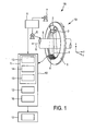
- Fig. 1 shows schematically and exemplarily an imaging apparatus for generating an image of a region of interest.
- the imaging apparatus is a computed tomography apparatus 18.
- the computed tomography apparatus 18 includes a gantry 1 which is capable by of rotation about a rotational axis R which extends parallel to the z direction.
- a radiation source 2, which is, in this embodiment, an x-ray tube, is mounted on the gantry 1.
- the radiation source 2 is provided with a collimator 3, which forms, in this embodiment, a conical radiation beam 4 from the radiation generated by the radiation source 2.
- the radiation traverses an object (not shown), such as a patient, and a region of interest, which is preferentially located within the object, in an examination zone 5, which is, in this embodiment, cylindrical.
- an examination zone 5 which is, in this embodiment, cylindrical.
- the radiation beam 4 is incident on a detection device 6, which comprises a two-dimensional detection surface.
- the detection device 6 is mounted on the gantry 1.
- the computed tomography apparatus 18 comprises two motors 7, 8.
- the gantry is driven at a preferably constant but adjustable angular speed by the motor 7.
- the motor 8 is provided for displacing the object, for example, a patient, with arranged on a patient table in the examination zone 5, parallel to the direction of the rotational axis R or the z axis.
- the motors 7, 8 are controlled by a control unit 9, for instance, such that the radiation source 2 and the examination zone 5 and, thus, the region of interest within the examination zone 5, move relative to each other along a helical trajectory.
- the object or the examination zone 5 is not moved, but that only the radiation source 2 is rotated, i. e.
- the collimator 3 can be adapted for forming another beam shape, in particular, a fan beam
- the detection device 6 can comprise a detection surface, which is shaped corresponding to the other beam shape, in particular, to the fan beam.
- the detection device 6 During a relative movement of the radiation source 2 and the examination zone 5 the detection device 6 generates projection data depending on the radiation incident on the detection surface of the detection device 6. Therefore, the radiation source 2, the elements for moving the radiation source 2 relative to the examination zone 5, in particular, the motor 7, 8 and the gantry 1, and the detection device 6 form an acquisition unit 19 for acquiring projection data of the region of interest.
- the projection data are provided to an reconstruction apparatus 10 for iteratively reconstructing an image of the region of interest from the acquired projection data.
- the reconstruction apparatus 1 comprises a forward projection apparatus 11 for performing a forward projection through an image of the region of interest for generating simulated projection data, a backprojection unit 12 for backprojecting data, which are based on at least one of the acquired projection data and the simulated projection data, for generating an image, and a control unit 16 for controlling the forward projection apparatus 11 and the backprojection unit 12 such that in an iteration step a forward projection and a backprojection are performed.
- the iterative reconstruction is initialized with an initial predefined image, which can, for example, only comprise zeros as image elements.
- the actual image which is, in the beginning, the initial image, is forward projected by the forward projection apparatus for generating simulated projection data.
- the acquired projection data and the simulated projection data can be substracted from each other, and in the same iteration step the difference can be backprojected by the backprojection unit for updating the actual image.
- the control unit 16 is preferentially adapted to terminate the iterative reconstruction, if a termination condition is fulfilled.
- the termination condition is, for example, that a predefined number of iterations has been reached or that a deviation of the updated actual image and the actual image before being updated in the current iteration step is smaller than a predefined threshold.
- the image generated by the reconstruction apparatus 10 is provided to a display 17 for displaying the generated image.
- the reconstruction apparatus 10 is preferably controlled by the control unit 9.
- the control unit 9 can also perform the control, which is, in this embodiment, performed by the control unit 16. In that case, the reconstruction apparatus 10 may not comprise the control unit 16.
- the forward projection apparatus 11 comprises a ray providing unit 13 for providing rays traversing the actual image for generating projection values forming the simulated projection data.
- the rays are fictive rays emanating from a fictive radiation source.
- the rays are provided such that they simulate the acquisition of the real measured projection data.
- the fictive radiation source corresponds therefore to the real radiation source 2.
- a movement of the fictive radiation source is simulated, which corresponds to the real movement performed by the real radiation source 2 while acquiring the real measured projection data.
- the forward projection apparatus is adapted to simulate the acquisition geometry used while acquiring the real measured projection data.
- the forward projection apparatus further comprises an interpolation unit 14 for determining interpolated values located on the provided rays, wherein the interpolation unit 14 is adapted to apply an interpolation kernel to a plurality of image elements of the image for determining the interpolated values, and a summation unit 15 for summing the interpolated values located on a respective ray for determining a projection value for the respective ray.
- At least one of the number of provided rays, a ray spacing between the provided rays and a kernel width of the interpolation kernel is varied depending on the ray width relative to an effective image element spacing between the image elements of the image, wherein the image elements are arranged in a grid having several main axes, and wherein the effective image element spacing is defined as a projection of an image element spacing parallel to a main axis of the grid onto a line being perpendicular to the respective ray.
- a first number of rays 20 is provided such that the ray width of the first number of rays 20 is smaller than or equal to the effective image element spacing.
- a second number of rays 21 is provided such that the ray width of the second number of rays 21 is smaller than or equal to the effective image element spacing, wherein the second number of rays 21 is larger than the first number of rays 20.
- the second number of rays 21 is twice the first number of rays 20.
- the image 22 comprises image elements 24 arranged in a rectangular grid having rectangular main axes 25, 26.
- the rays 20, 21 diverge such that for the same number of rays, i.e. the first number of rays 20 or the second number of rays 21, the ray spacing increases with increasing distance to the fictive radiation source 23.
- the ray width which is, in this example, defined by the half distance to the directly neighbored rays, increases with increasing distance to the fictive radiation source 23.
- the interpolation unit 14 determines interpolated values on the first number of rays 20 and on the second number of rays 21 and the rays of the first number of rays 20 and of the second number of rays 21 are assigned to detection elements 31 of a detection unit 32, wherein the summation unit 15 determines a projection value for a respective detection element 31 by summing the interpolated values on the rays of the first number of rays 20 and the second number rays 21, which are assigned to the respective detection element 31.
- the first region 29 and the second region 30 overlap in a transition region 33, and the summation unit 15 is adapted to weightedly sum the interpolated values on the first number of rays 20 and on the second number of rays 21 in the transition region 33.
- This weighting is exemplarily illustrated in Fig. 3.
- Fig. 3 shows weights w, which are used for weighting interpolated values on rays directed to a certain detection element 31, depending on the distance d to the fictive radiation source 23.
- the interpolated values on a ray of the first number of rays 20 is weighted with 1.0 as indicated by a first curve 91.
- the interpolated values on the two rays of the second number of rays 21, which are directed to the same respective detection element 31, are weighted by 0.5 as indicated by the second curve 90.
- the interpolated values on the ray of the first number of rays 20, which is directed to the respective detection element 31 is weighted with a weight, which decreases with increasing distance to the fictive radiation source 23 as indicated by the first curve 91, and the weights for the interpolated values on the two rays of the second number of rays, which are directed to the same respective detection element 31, increase with increasing distance to the fictive radiation source 23.
- the weighted interpolated values which are located on rays directed to the same respective detection element 31, are added for generating a projection value for the respective detection element 31.
- the weights are preferentially chosen such that for a certain distance d to the fictive radiation source the sum of the weights for interpolated values on rays directed to the same detection element 31 is one.
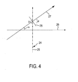
- Fig. 4 illustrates exemplarily the effective image element spacing b .
- Fig. 4 shows some image elements 24 arranged along a first main axis 25 and a second main axis 26 of the grid comprising the image elements 24. The further image elements 24 are not shown in Fig. 4 for clarity reasons.
- a ray 27 is shown, which encloses an angle ⁇ , with the second main axis 26.
- the image element spacing a is projected onto a straight line 28, which is perpendicular to the ray 27, for determining the effective image element spacing b .
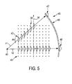
- Fig. 5 illustrates a known forward projection procedure, wherein several fictive rays, which emanate from a fictive radiation source 40 and from which only two fictive rays 41, 42 are exemplarily shown, traverse an image 39 comprising image elements 49.
- Image elements which are arranged parallel to a main axis 38 of a grid of the image elements 49 are interpolated by using interpolation kernels 43 having a kernel width 44.
- the effective kernel width with respect to ray 41 which is defined as the projection of the kernel width 44 arranged parallel to the main axis 38 of the grid onto a line being perpendicular to the respective ray 41, is smaller than the effective kernel width with respect to the ray 42.
- interpolated values which are located on the respective ray 41 or 42, are calculated by using the interpolation kernels 43, wherein the interpolated values located on the ray 41 are summed for generating a first projection value and the interpolated values located on the rays 42 are summed for generating a second projection value. Since the effective kernel width of the interpolation kernels is different with respect to the rays 41, 42, artifacts are caused in the calculated projection values, which may lead to artifacts in the finally reconstructed image.
- the ray providing unit 13 can be adapted to provide rays 50, 51 which are assigned to detection elements 62 of a detection unit 61 as schematically and exemplarily illustrated in Fig. 6 .
- Multiple rays are assigned to the same detection element 62.
- the ray spacing between the multiple rays assigned to the same detection element 62 is chosen such that, if the ray width relative to the effective image element spacing is larger, the ray spacing is larger, wherein, in this embodiment, the ray width is assumed as being constant, i.e. with decreasing effective image element spacing, the ray width relative to the effective image element spacing increases.
- the rays 51 have a larger ray width relative to the effective image element spacing and, thus, the spacing between the rays 51 is larger than the spacing between the rays 50, for which the ray width relative to the effective image element spacing is smaller.
- the interpolation kernels are arranged such that the kernel widths are arranged parallel to the main axis 55 of the grid, in which the image elements 54 of the image 52 are positioned.
- Each of the rays 50, 51, which emanates from the fictive radiation source 53, is related to an effective kernel width, wherein the effective kernel width is defined as the projection of the kernel width arranged parallel to the main axis 55 of the grid onto a line being perpendicular to the respective ray.
- the effective kernel widths of the rays assigned to the same detection element define an effective detection element kernel width 59, 60, wherein the ray spacing of the rays assigned to the same detection element 62 of the detection unit 61 is chosen such that the effective detection element kernel width 59, 60 of multiple detection elements are equal.
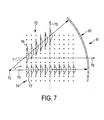
- a further embodiment, which allows achieving an equal effective kernel width perpendicular to the respective ray 70, 71 directed to a respective detection element 82 of a detection unit 81, is schematically and exemplarily illustrated in Fig. 7 .
- the interpolation unit 14 is adapted to provide an interpolation kernel 77, 78 having a larger width, if the ray width relative to the effective image element spacing is larger.
- the ray width is assumed as being constant, i.e. with decreasing effective image element spacing, the ray width relative to the effective image element spacing increases.
- the interpolation unit 14 is further adapted to provide the interpolation kernel 77, 78 such that the effective kernel width is equal for each ray, 70, 71, in particular, such that their kernel width depends on the cosine of an angle ⁇ between the respective ray and a line perpendicular to the main axis 75 of the grid.
- the image can be represented by multi-dimensional Kaiser-Bessel windows as disclosed in, for example, the article "Multi-dimensional digital image representation using generalized Kaiser-Bessel window functions", Lewitt, J.Opt.Soc.Am.A, vol 7, no 10 (2000)).
- the function I 0 is the zero order Bessel function.
- the base function can depend on a higher order Bessel function.
- Spherically symmetric basis functions like the Kaiser-Bessel function are often called "blobs".
- the interpolation function, i.e. the interpolation kernel, perpendicular to the respective ray can in this case be called the "footprint" of the blob.
- the interpolation kernel can depend on the cosine of an angle ⁇ between the respective ray and a line perpendicular to the main axis, which is preferentially the interpolation axis, of the grid.
- Equation (3) can be used, if the interpolation axis is the y axis. If the interpolation axis is the x axis, in equation (3) y can be replaced by x.
- a one-dimensional interpolation kernel is used, which is arranged along a first main axis or a second main axis of the grid, which may be regarded as an x axis and an y axis, respectively.
- two-dimensional interpolation kernels are preferentially used for performing the interpolations in a first main grid plane or a second main grid plane, wherein the first main grid plane and the second main grid plane are preferentially parallel to the x - z plane and the y - z plane, respectively.
- the two-dimensional interpolation kernel in the respective plane can be stretched by the factor 1/cos ( ⁇ ) in the x direction or in the y direction, and by the factor 1 / cos ( ⁇ ) in the z direction, wherein the angle ⁇ is defined as the angle between the respective ray and the x - z plane if the main grid plane is the y- z plane and as the angle between the respective ray and the y - z plane if the main grid plane is the x - z plane, and wherein the angle ⁇ is the angle between the respective ray and the x-y plane, often called the cone-angle of the respective ray.
- the image representation can, of course, also be based on other basis functions like a truncated Gaussian basis function or a generalized Kaiser-Bessel function with parameters, which are different to the parameters mentioned above with reference to equation (1), as, for example, disclosed in the article " Practical Considerations for 3D Image Reconstruction using Spherically Symmetric Basis Functions" by Matej and Lewitt, IEEE TMI, vol 15, no 1, pages 68-78 (1996 ).
- step 101 rays are provided, which traverse the image, and, in step 102, interpolated values are determined, which are located on the provided rays, wherein an interpolation kernel is applied to a plurality of image elements of the image for determining the interpolated values, wherein at least one of the number of provided rays, a ray spacing between the provided rays and the kernel width of the interpolation kernel is varied depending on the ray width relative to an effective image element spacing between image elements of the image, wherein the image elements are arranged in a grid having several main axes, and wherein the effective image element spacing is defined as a projection of an image element spacing parallel to a main axis of the grid onto a line being perpendicular to the respective ray.
- step 103 the interpolated values located on a respective ray are summed for determining a projection value for the respective ray.
- step 201 projection data of the region of interest are acquired, for example, by using the acquisition unit 19 described above with reference to Fig. 1 .
- step 202 the acquired projection data are used for iteratively reconstructing an image of the region of interest.
- the iteration starts with an initial image, which may be an image having zero values or which may be another image, and in an iteration step a) a forward projection through the actual image, which is in the beginning the initial image, is performed, as described above with reference to Fig. 8 , for determining simulated projection data, which correspond to the acquired projection data; b) a difference between the simulated projection data and the acquired projection data is calculated; and c) the difference is backprojected for updating the actual image of the region of interest.
- This iteration step is repeated until a termination condition is fulfilled.
- the termination condition is fulfilled if, for example, the iteration step has been repeated a predefined number of times, the difference between the acquired projection data and the simulated projection data is below a predefined threshold or if a deviation of the actual image updated in the present iteration step from the image, which has been updated in the previous iteration step, is below a threshold.
- the iteratively reconstructed image of the region of interest is shown on the display 17.
- Iterative reconstruction can be used to decrease the x-ray dose applied to persons or animals during a computed tomography scan.
- a shortcoming of iterative reconstruction is the high computational load during reconstruction due to the need for performing several forward projections and backprojections.
- the forward projection operation and the backprojection operation are preferentially implemented by using graphics processing units (GPUs).
- the forward projection apparatus and the backprojection unit are preferentially GPUs.
- the forward projection can be implemented in a very efficient manner by making use of the hardware implementation of three-dimensional textures in a GPU.
- the forward projection can be implemented as so-called ray-driven forward projection. For example, for each detector pixel one or several rays can be casted through the image and the desired detector value, i.e. the desired projection value, is obtained by sampling the image along the one or several rays and by accumulating these samples.
- the desired detector value i.e. the desired projection value
- rays can be used, where needed, adaptively, i.e. an oversampling can be adaptively performed along the way from the fictive radiation source to the respective detection element.
- an oversampling can be adaptively performed along the way from the fictive radiation source to the respective detection element.
- two rays per detection element 31 are used for sampling the image, in order to suppress aliasing artefacts. If the image element spacing in the image domain is equal to the ray spacing at the isocenter of the acquisition unit, one ray per detection element may be used to calculate the contribution of the image from the radiation source up to the isocenter without aliasing.
- the ray spacing is larger than the image element spacing and, in the embodiment described above with reference to Fig. 2 , two sub-rays are used per detection element to calculate the contribution of the remaining part of the image to the respective projection value.
- there is a small transition range i.e. the transition region 33, where, in this embodiment, three rays per detection element are calculated.
- this transition area relative weights as shown in, for example, Fig. 3 are preferentially used.
- the additional effort for anti-aliasing can be reduced from a factor of 2 to 3/2 in the fan-beam case and from a factor of 4 to 5/8 in the cone-beam case, if the ray configuration described above with reference to Fig. 2 is used, i.e. if for the ray path from the radiation source up to the point where the ray density matches the image element density, only one ray per detection element is casted, and if for the further way to the respective detection element two sub-rays are casted through the image, which may be a two-dimensional or a three-dimensional image.
- Fig. 5 illustrates the forward projection proposed by Joseph, wherein for each ray a linear interpolation is performed within each grid line being parallel to the main axis 38.
- the linear interpolation is illustrated by triangular interpolation kernels. If the image is a three-dimensional image, the linear interpolation is performed within each main grid plane, which corresponds to the lines parallel to the main axis in the two-dimensional case.
- the interpolation kernel has a constant width with respect to the main grid axis. This implies that the effective kernel width of the interpolation kernel perpendicular to the respective ray varies by a factor of ⁇ 2. This is indicated in Fig. 5 by triangles 47, 48 at the respective detector element positions. Ray 42 shown in Fig. 5 is casted perpendicular to the main axis 38. The full-width-at-half-maximum of the effective interpolation kernel is equal to the image element spacing. The other ray 41 is casted almost at 45 degrees with respect to the main axis 38 such that the effective kernel width for this other ray 41 is about the image elements spacing divided by ⁇ 2.
- rays per detection element can be casted, for example, in order to avoid aliasing artifacts.
- the effect of the varying effective kernel width can be compensated by a properly selected spacing of the rays, which are directed to the same respective detection element and which may be regarded as sub-rays, as described above with reference to Fig. 6 .
- a properly selected spacing of the rays By using a larger spacing between the rays with the smaller effective kernel width it can be achieved that the total effective kernel width of the average of the, in the embodiment described above with reference to Fig. 6 , three individual rays is kept constant for all ray angles.
- the invention is not restricted to a certain number of individual rays casted per detection elements through the image. For example, also more than three rays can be casted per detection element.
- Fig. 7 An alternative way for handling the problem of varying effective kernel widths is described above with reference to Fig. 7 .
- Higher order interpolation kernels are used instead of a linear interpolation kernel, which may be used in the two-dimensional case, or instead of a bi-linear interpolation kernel, which may be used in a three-dimensional case, within each line being parallel to main grid line or axis in the two-dimensional case or within each main grid plane in the three-dimensional case.
- the kernel width can be adjusted to the angle between the respective ray and the lines being parallel to the main axis or main grid plane, respectively, to ensure a constant kernel width perpendicular to the respective ray.
- the interpolation kernels hitting the lines being parallel to the main axis or main grid planes, respectively, at a hitting angle can be stretched by the 1/cosine of the hitting angle, wherein the hitting angle can be the angle between a ray perpendicular to a main axis or main grid line and another ray, for which the interpolation kernel shall be defined.
- the forward projection apparatus, the reconstruction apparatus and the imaging apparatus can be adapted to allow reconstructing two-dimensional images and/or three-dimensional images.
- the forward projection apparatus is preferentially adapted to cast fictive rays to all detection elements of the detection unit, wherein one or several rays per detection element can be casted.
- the invention relates to a forward projection apparatus for performing a forward projection through an image, wherein at least one of a number of rays for performining the forward projection and a ray spacing between the rays is varied depending on the ray width relative to an effective image element spacing between image elements of the image.
- This allows reducing artifacts in simulated projection data and, thus, in an image, which is iteratively reconstructed by using the simulated projection data. For example, if the number of provided rays and/or the ray spacing between the provided rays is varied, aliasing artifacts can be reduced.
- the ray spacing between the provided rays and/or the kernel width of the interpolation kernel is varied, artifacts caused by varying effective kernel widths may be reduced.
Landscapes
- Physics & Mathematics (AREA)
- General Physics & Mathematics (AREA)
- Engineering & Computer Science (AREA)
- Theoretical Computer Science (AREA)
- Apparatus For Radiation Diagnosis (AREA)
- Projection Apparatus (AREA)
- Image Processing (AREA)
Priority Applications (1)
| Application Number | Priority Date | Filing Date | Title |
|---|---|---|---|
| EP11799324.6A EP2643815B1 (en) | 2010-11-25 | 2011-11-16 | Forward projection apparatus |
Applications Claiming Priority (3)
| Application Number | Priority Date | Filing Date | Title |
|---|---|---|---|
| EP10192558 | 2010-11-25 | ||
| PCT/IB2011/055123 WO2012069964A1 (en) | 2010-11-25 | 2011-11-16 | Forward projection apparatus |
| EP11799324.6A EP2643815B1 (en) | 2010-11-25 | 2011-11-16 | Forward projection apparatus |
Publications (2)
| Publication Number | Publication Date |
|---|---|
| EP2643815A1 EP2643815A1 (en) | 2013-10-02 |
| EP2643815B1 true EP2643815B1 (en) | 2014-07-23 |
Family
ID=45375465
Family Applications (1)
| Application Number | Title | Priority Date | Filing Date |
|---|---|---|---|
| EP11799324.6A Active EP2643815B1 (en) | 2010-11-25 | 2011-11-16 | Forward projection apparatus |
Country Status (7)
| Country | Link |
|---|---|
| US (1) | US9002090B2 (pt) |
| EP (1) | EP2643815B1 (pt) |
| JP (1) | JP5913351B2 (pt) |
| CN (1) | CN103229211B (pt) |
| BR (1) | BR112013012676A2 (pt) |
| RU (1) | RU2589386C2 (pt) |
| WO (1) | WO2012069964A1 (pt) |
Families Citing this family (10)
| Publication number | Priority date | Publication date | Assignee | Title |
|---|---|---|---|---|
| EP2661736B1 (en) * | 2011-01-06 | 2014-04-30 | Koninklijke Philips N.V. | Imaging system for imaging an object |
| WO2012095713A1 (en) * | 2011-01-10 | 2012-07-19 | Koninklijke Philips Electronics N.V. | Dual -energy tomographic imaging system |
| CN103976753B (zh) * | 2013-02-08 | 2016-08-17 | 株式会社日立制作所 | Ct图像生成装置和ct图像生成方法 |
| KR102060659B1 (ko) | 2013-03-20 | 2019-12-30 | 삼성전자주식회사 | 영상 처리를 위한 투사 및 역투사 방법 및 그 영상 처리 장치 |
| CN103279929B (zh) * | 2013-05-25 | 2015-11-18 | 北京工业大学 | 一种基于余弦积分的ct图像金属轨迹预测和伪影去除方法 |
| CN103617598B (zh) * | 2013-11-10 | 2016-08-31 | 北京工业大学 | 一种基于轨迹的ct图像金属伪影去除方法 |
| JP6370280B2 (ja) * | 2015-09-16 | 2018-08-08 | 富士フイルム株式会社 | 断層画像生成装置、方法およびプログラム |
| US10789738B2 (en) * | 2017-11-03 | 2020-09-29 | The University Of Chicago | Method and apparatus to reduce artifacts in a computed-tomography (CT) image by iterative reconstruction (IR) using a cost function with a de-emphasis operator |
| WO2019118387A1 (en) * | 2017-12-11 | 2019-06-20 | Dentsply Sirona Inc. | Methods, systems, apparatuses, and computer program products for extending the field of view of a sensor and obtaining a synthetic radiagraph |
| KR20190118075A (ko) * | 2018-04-09 | 2019-10-17 | 삼성전자주식회사 | 단층 촬영 장치 및 그에 따른 단층 영상 처리 방법 |
Family Cites Families (17)
| Publication number | Priority date | Publication date | Assignee | Title |
|---|---|---|---|---|
| US4636952A (en) * | 1984-12-03 | 1987-01-13 | General Electric Company | Method and apparatus for back projection image reconstruction using virtual equi-spaced detector array |
| CN1164904A (zh) | 1994-09-06 | 1997-11-12 | 纽约州州立大学研究基金会 | 实时立体显象设备与方法 |
| EP0992023A4 (en) | 1997-04-15 | 2001-04-18 | Res Foundation Of | DEVICE AND METHOD FOR PARALLEL AND PERSPECTIVE REAL-TIME VOLUME VISUALIZATION |
| EP1439492A1 (en) | 1998-02-23 | 2004-07-21 | Algotec Systems Ltd | Raycasting system and method |
| AU758086B2 (en) | 1998-02-23 | 2003-03-13 | Algotec Systems Ltd. | Raycasting system and method |
| JP3827917B2 (ja) | 2000-05-18 | 2006-09-27 | 株式会社日立製作所 | 液晶表示装置および半導体集積回路装置 |
| US6587537B1 (en) * | 2002-04-01 | 2003-07-01 | Ge Medical Systems Global Technology Company, Llc | Methods and apparatus for multi-slice image reconstruction |
| US6724856B2 (en) * | 2002-04-15 | 2004-04-20 | General Electric Company | Reprojection and backprojection methods and algorithms for implementation thereof |
| CN1517073A (zh) * | 2003-01-22 | 2004-08-04 | 西门子公司 | 带有至少两组辐射源-检测器组件的成像断层造影设备 |
| DE602004024682D1 (de) * | 2003-07-15 | 2010-01-28 | Koninkl Philips Electronics Nv | Ung |
| US7348975B2 (en) | 2004-12-28 | 2008-03-25 | Intel Corporation | Applications of interval arithmetic for reduction of number of computations in ray tracing problems |
| US7362330B2 (en) | 2005-09-15 | 2008-04-22 | International Business Machines Corporation | Adaptive span computation when ray casting |
| DE102005051620A1 (de) * | 2005-10-27 | 2007-05-03 | Siemens Ag | Verfahren zur Rekonstruktion einer tomographischen Darstellung eines Objektes |
| CN100495439C (zh) * | 2005-11-21 | 2009-06-03 | 清华大学 | 采用直线轨迹扫描的图像重建系统和方法 |
| JP4938335B2 (ja) * | 2006-04-03 | 2012-05-23 | ジーイー・メディカル・システムズ・グローバル・テクノロジー・カンパニー・エルエルシー | X線ct装置 |
| US8116426B2 (en) * | 2008-11-11 | 2012-02-14 | Kabushiki Kaisha Toshiba | Computed tomography device and method using circular-pixel position-adaptive interpolation |
| JP5404767B2 (ja) * | 2009-03-04 | 2014-02-05 | 株式会社日立メディコ | X線ct装置及び画像修正プログラム |
-
2011
- 2011-11-16 CN CN201180056283.6A patent/CN103229211B/zh active Active
- 2011-11-16 US US13/988,349 patent/US9002090B2/en active Active
- 2011-11-16 WO PCT/IB2011/055123 patent/WO2012069964A1/en active Application Filing
- 2011-11-16 RU RU2013128867/08A patent/RU2589386C2/ru not_active IP Right Cessation
- 2011-11-16 JP JP2013540463A patent/JP5913351B2/ja not_active Expired - Fee Related
- 2011-11-16 BR BR112013012676A patent/BR112013012676A2/pt not_active IP Right Cessation
- 2011-11-16 EP EP11799324.6A patent/EP2643815B1/en active Active
Also Published As
| Publication number | Publication date |
|---|---|
| JP2013543784A (ja) | 2013-12-09 |
| US9002090B2 (en) | 2015-04-07 |
| BR112013012676A2 (pt) | 2016-08-23 |
| RU2589386C2 (ru) | 2016-07-10 |
| RU2013128867A (ru) | 2014-12-27 |
| EP2643815A1 (en) | 2013-10-02 |
| US20130243297A1 (en) | 2013-09-19 |
| CN103229211B (zh) | 2016-05-11 |
| CN103229211A (zh) | 2013-07-31 |
| JP5913351B2 (ja) | 2016-04-27 |
| WO2012069964A1 (en) | 2012-05-31 |
Similar Documents
| Publication | Publication Date | Title |
|---|---|---|
| EP2643815B1 (en) | Forward projection apparatus | |
| Thibault et al. | A three‐dimensional statistical approach to improved image quality for multislice helical CT | |
| US8135186B2 (en) | Method and system for image reconstruction | |
| US10896486B2 (en) | Denoising method and system for preserving clinically significant structures in reconstructed images using adaptively weighted anisotropic diffusion filter | |
| RU2510080C2 (ru) | Устройство для обработки изображения, способ обработки изображения и среда долговременного хранения информации | |
| EP1800264B1 (en) | Image reconstruction with voxel dependent interpolation | |
| US8655033B2 (en) | Iterative reconstruction | |
| US7756312B2 (en) | Methods and apparatus for noise estimation | |
| US9600924B2 (en) | Iterative reconstruction of image data in CT | |
| WO2015016328A1 (ja) | X線CT(Computed Tomography)装置、画像処理装置、画像処理方法及び記憶媒体 | |
| NL1028225C2 (nl) | Werkwijze en inrichting voor artefactreductie in met een kegelbundel werkende CT-beeldreconstructie. | |
| US10789738B2 (en) | Method and apparatus to reduce artifacts in a computed-tomography (CT) image by iterative reconstruction (IR) using a cost function with a de-emphasis operator | |
| Matej et al. | Performance of the Fourier rebinning algorithm for PET with large acceptance angles | |
| US9489752B2 (en) | Ordered subsets with momentum for X-ray CT image reconstruction | |
| JP6026214B2 (ja) | 連続マルチスケール再構成において詳細画像を補うx線コンピュータ断層撮像装置(x線ct装置)、医用画像処理装置及び医用画像処理方法 | |
| JP2004188163A (ja) | 断層撮影装置 | |
| JP2016152916A (ja) | X線コンピュータ断層撮像装置及び医用画像処理装置 | |
| US7933375B2 (en) | Ray consistency based reconstruction of helical cone beam data | |
| Sunnegårdh et al. | Regularized iterative weighted filtered backprojection for helical cone‐beam CT | |
| US20130094736A1 (en) | Method and system for substantially reducing streak artifacts in helical cone beam computer tomography (ct) | |
| US20210174561A1 (en) | Stochastic backprojection for 3d image reconstruction | |
| JP4387758B2 (ja) | Spect装置及びspect画像再構成方法 | |
| CN106651809B (zh) | 去除图像中伪影的方法及装置 | |
| JP2006527618A (ja) | 余剰な測定値を使用するコンピュータ断層撮影法 | |
| Brokish et al. | Iterative circular conebeam CT reconstruction using fast hierarchical backprojection/reprojection operators |
Legal Events
| Date | Code | Title | Description |
|---|---|---|---|
| PUAI | Public reference made under article 153(3) epc to a published international application that has entered the european phase |
Free format text: ORIGINAL CODE: 0009012 |
|
| 17P | Request for examination filed |
Effective date: 20130625 |
|
| AK | Designated contracting states |
Kind code of ref document: A1 Designated state(s): AL AT BE BG CH CY CZ DE DK EE ES FI FR GB GR HR HU IE IS IT LI LT LU LV MC MK MT NL NO PL PT RO RS SE SI SK SM TR |
|
| GRAP | Despatch of communication of intention to grant a patent |
Free format text: ORIGINAL CODE: EPIDOSNIGR1 |
|
| DAX | Request for extension of the european patent (deleted) | ||
| INTG | Intention to grant announced |
Effective date: 20140219 |
|
| GRAS | Grant fee paid |
Free format text: ORIGINAL CODE: EPIDOSNIGR3 |
|
| GRAA | (expected) grant |
Free format text: ORIGINAL CODE: 0009210 |
|
| AK | Designated contracting states |
Kind code of ref document: B1 Designated state(s): AL AT BE BG CH CY CZ DE DK EE ES FI FR GB GR HR HU IE IS IT LI LT LU LV MC MK MT NL NO PL PT RO RS SE SI SK SM TR |
|
| REG | Reference to a national code |
Ref country code: GB Ref legal event code: FG4D |
|
| REG | Reference to a national code |
Ref country code: CH Ref legal event code: EP |
|
| REG | Reference to a national code |
Ref country code: IE Ref legal event code: FG4D |
|
| REG | Reference to a national code |
Ref country code: AT Ref legal event code: REF Ref document number: 679241 Country of ref document: AT Kind code of ref document: T Effective date: 20140815 |
|
| REG | Reference to a national code |
Ref country code: DE Ref legal event code: R096 Ref document number: 602011008649 Country of ref document: DE Effective date: 20140904 |
|
| REG | Reference to a national code |
Ref country code: AT Ref legal event code: MK05 Ref document number: 679241 Country of ref document: AT Kind code of ref document: T Effective date: 20140723 |
|
| REG | Reference to a national code |
Ref country code: NL Ref legal event code: VDEP Effective date: 20140723 |
|
| REG | Reference to a national code |
Ref country code: LT Ref legal event code: MG4D |
|
| PG25 | Lapsed in a contracting state [announced via postgrant information from national office to epo] |
Ref country code: LT Free format text: LAPSE BECAUSE OF FAILURE TO SUBMIT A TRANSLATION OF THE DESCRIPTION OR TO PAY THE FEE WITHIN THE PRESCRIBED TIME-LIMIT Effective date: 20140723 Ref country code: ES Free format text: LAPSE BECAUSE OF FAILURE TO SUBMIT A TRANSLATION OF THE DESCRIPTION OR TO PAY THE FEE WITHIN THE PRESCRIBED TIME-LIMIT Effective date: 20140723 Ref country code: GR Free format text: LAPSE BECAUSE OF FAILURE TO SUBMIT A TRANSLATION OF THE DESCRIPTION OR TO PAY THE FEE WITHIN THE PRESCRIBED TIME-LIMIT Effective date: 20141024 Ref country code: SE Free format text: LAPSE BECAUSE OF FAILURE TO SUBMIT A TRANSLATION OF THE DESCRIPTION OR TO PAY THE FEE WITHIN THE PRESCRIBED TIME-LIMIT Effective date: 20140723 Ref country code: BG Free format text: LAPSE BECAUSE OF FAILURE TO SUBMIT A TRANSLATION OF THE DESCRIPTION OR TO PAY THE FEE WITHIN THE PRESCRIBED TIME-LIMIT Effective date: 20141023 Ref country code: NO Free format text: LAPSE BECAUSE OF FAILURE TO SUBMIT A TRANSLATION OF THE DESCRIPTION OR TO PAY THE FEE WITHIN THE PRESCRIBED TIME-LIMIT Effective date: 20141023 Ref country code: FI Free format text: LAPSE BECAUSE OF FAILURE TO SUBMIT A TRANSLATION OF THE DESCRIPTION OR TO PAY THE FEE WITHIN THE PRESCRIBED TIME-LIMIT Effective date: 20140723 Ref country code: PT Free format text: LAPSE BECAUSE OF FAILURE TO SUBMIT A TRANSLATION OF THE DESCRIPTION OR TO PAY THE FEE WITHIN THE PRESCRIBED TIME-LIMIT Effective date: 20141124 |
|
| PG25 | Lapsed in a contracting state [announced via postgrant information from national office to epo] |
Ref country code: PL Free format text: LAPSE BECAUSE OF FAILURE TO SUBMIT A TRANSLATION OF THE DESCRIPTION OR TO PAY THE FEE WITHIN THE PRESCRIBED TIME-LIMIT Effective date: 20140723 Ref country code: RS Free format text: LAPSE BECAUSE OF FAILURE TO SUBMIT A TRANSLATION OF THE DESCRIPTION OR TO PAY THE FEE WITHIN THE PRESCRIBED TIME-LIMIT Effective date: 20140723 Ref country code: LV Free format text: LAPSE BECAUSE OF FAILURE TO SUBMIT A TRANSLATION OF THE DESCRIPTION OR TO PAY THE FEE WITHIN THE PRESCRIBED TIME-LIMIT Effective date: 20140723 Ref country code: AT Free format text: LAPSE BECAUSE OF FAILURE TO SUBMIT A TRANSLATION OF THE DESCRIPTION OR TO PAY THE FEE WITHIN THE PRESCRIBED TIME-LIMIT Effective date: 20140723 Ref country code: NL Free format text: LAPSE BECAUSE OF FAILURE TO SUBMIT A TRANSLATION OF THE DESCRIPTION OR TO PAY THE FEE WITHIN THE PRESCRIBED TIME-LIMIT Effective date: 20140723 Ref country code: HR Free format text: LAPSE BECAUSE OF FAILURE TO SUBMIT A TRANSLATION OF THE DESCRIPTION OR TO PAY THE FEE WITHIN THE PRESCRIBED TIME-LIMIT Effective date: 20140723 Ref country code: CY Free format text: LAPSE BECAUSE OF FAILURE TO SUBMIT A TRANSLATION OF THE DESCRIPTION OR TO PAY THE FEE WITHIN THE PRESCRIBED TIME-LIMIT Effective date: 20140723 Ref country code: IS Free format text: LAPSE BECAUSE OF FAILURE TO SUBMIT A TRANSLATION OF THE DESCRIPTION OR TO PAY THE FEE WITHIN THE PRESCRIBED TIME-LIMIT Effective date: 20141123 |
|
| REG | Reference to a national code |
Ref country code: DE Ref legal event code: R097 Ref document number: 602011008649 Country of ref document: DE |
|
| PG25 | Lapsed in a contracting state [announced via postgrant information from national office to epo] |
Ref country code: DK Free format text: LAPSE BECAUSE OF FAILURE TO SUBMIT A TRANSLATION OF THE DESCRIPTION OR TO PAY THE FEE WITHIN THE PRESCRIBED TIME-LIMIT Effective date: 20140723 Ref country code: SK Free format text: LAPSE BECAUSE OF FAILURE TO SUBMIT A TRANSLATION OF THE DESCRIPTION OR TO PAY THE FEE WITHIN THE PRESCRIBED TIME-LIMIT Effective date: 20140723 Ref country code: CZ Free format text: LAPSE BECAUSE OF FAILURE TO SUBMIT A TRANSLATION OF THE DESCRIPTION OR TO PAY THE FEE WITHIN THE PRESCRIBED TIME-LIMIT Effective date: 20140723 Ref country code: EE Free format text: LAPSE BECAUSE OF FAILURE TO SUBMIT A TRANSLATION OF THE DESCRIPTION OR TO PAY THE FEE WITHIN THE PRESCRIBED TIME-LIMIT Effective date: 20140723 Ref country code: IT Free format text: LAPSE BECAUSE OF FAILURE TO SUBMIT A TRANSLATION OF THE DESCRIPTION OR TO PAY THE FEE WITHIN THE PRESCRIBED TIME-LIMIT Effective date: 20140723 Ref country code: RO Free format text: LAPSE BECAUSE OF FAILURE TO SUBMIT A TRANSLATION OF THE DESCRIPTION OR TO PAY THE FEE WITHIN THE PRESCRIBED TIME-LIMIT Effective date: 20140723 |
|
| PLBE | No opposition filed within time limit |
Free format text: ORIGINAL CODE: 0009261 |
|
| STAA | Information on the status of an ep patent application or granted ep patent |
Free format text: STATUS: NO OPPOSITION FILED WITHIN TIME LIMIT |
|
| PG25 | Lapsed in a contracting state [announced via postgrant information from national office to epo] |
Ref country code: LU Free format text: LAPSE BECAUSE OF FAILURE TO SUBMIT A TRANSLATION OF THE DESCRIPTION OR TO PAY THE FEE WITHIN THE PRESCRIBED TIME-LIMIT Effective date: 20141116 Ref country code: MC Free format text: LAPSE BECAUSE OF FAILURE TO SUBMIT A TRANSLATION OF THE DESCRIPTION OR TO PAY THE FEE WITHIN THE PRESCRIBED TIME-LIMIT Effective date: 20140723 Ref country code: BE Free format text: LAPSE BECAUSE OF NON-PAYMENT OF DUE FEES Effective date: 20141130 |
|
| REG | Reference to a national code |
Ref country code: CH Ref legal event code: PL |
|
| 26N | No opposition filed |
Effective date: 20150424 |
|
| REG | Reference to a national code |
Ref country code: DE Ref legal event code: R082 Ref document number: 602011008649 Country of ref document: DE Representative=s name: MEISSNER, BOLTE & PARTNER GBR, DE Ref country code: DE Ref legal event code: R081 Ref document number: 602011008649 Country of ref document: DE Owner name: PHILIPS GMBH, DE Free format text: FORMER OWNER: PHILIPS INTELLECTUAL PROPERTY & STANDARDS GMBH, 20099 HAMBURG, DE Ref country code: DE Ref legal event code: R082 Ref document number: 602011008649 Country of ref document: DE Representative=s name: MEISSNER BOLTE PATENTANWAELTE RECHTSANWAELTE P, DE |
|
| PG25 | Lapsed in a contracting state [announced via postgrant information from national office to epo] |
Ref country code: LI Free format text: LAPSE BECAUSE OF NON-PAYMENT OF DUE FEES Effective date: 20141130 Ref country code: CH Free format text: LAPSE BECAUSE OF NON-PAYMENT OF DUE FEES Effective date: 20141130 |
|
| REG | Reference to a national code |
Ref country code: IE Ref legal event code: MM4A |
|
| REG | Reference to a national code |
Ref country code: FR Ref legal event code: ST Effective date: 20150731 |
|
| PG25 | Lapsed in a contracting state [announced via postgrant information from national office to epo] |
Ref country code: IE Free format text: LAPSE BECAUSE OF NON-PAYMENT OF DUE FEES Effective date: 20141116 |
|
| PG25 | Lapsed in a contracting state [announced via postgrant information from national office to epo] |
Ref country code: SI Free format text: LAPSE BECAUSE OF FAILURE TO SUBMIT A TRANSLATION OF THE DESCRIPTION OR TO PAY THE FEE WITHIN THE PRESCRIBED TIME-LIMIT Effective date: 20140723 Ref country code: FR Free format text: LAPSE BECAUSE OF NON-PAYMENT OF DUE FEES Effective date: 20141201 |
|
| PG25 | Lapsed in a contracting state [announced via postgrant information from national office to epo] |
Ref country code: SM Free format text: LAPSE BECAUSE OF FAILURE TO SUBMIT A TRANSLATION OF THE DESCRIPTION OR TO PAY THE FEE WITHIN THE PRESCRIBED TIME-LIMIT Effective date: 20140723 |
|
| GBPC | Gb: european patent ceased through non-payment of renewal fee |
Effective date: 20151116 |
|
| PG25 | Lapsed in a contracting state [announced via postgrant information from national office to epo] |
Ref country code: BE Free format text: LAPSE BECAUSE OF FAILURE TO SUBMIT A TRANSLATION OF THE DESCRIPTION OR TO PAY THE FEE WITHIN THE PRESCRIBED TIME-LIMIT Effective date: 20140723 Ref country code: MT Free format text: LAPSE BECAUSE OF FAILURE TO SUBMIT A TRANSLATION OF THE DESCRIPTION OR TO PAY THE FEE WITHIN THE PRESCRIBED TIME-LIMIT Effective date: 20140723 Ref country code: TR Free format text: LAPSE BECAUSE OF FAILURE TO SUBMIT A TRANSLATION OF THE DESCRIPTION OR TO PAY THE FEE WITHIN THE PRESCRIBED TIME-LIMIT Effective date: 20140723 Ref country code: HU Free format text: LAPSE BECAUSE OF FAILURE TO SUBMIT A TRANSLATION OF THE DESCRIPTION OR TO PAY THE FEE WITHIN THE PRESCRIBED TIME-LIMIT; INVALID AB INITIO Effective date: 20111116 |
|
| PG25 | Lapsed in a contracting state [announced via postgrant information from national office to epo] |
Ref country code: GB Free format text: LAPSE BECAUSE OF NON-PAYMENT OF DUE FEES Effective date: 20151116 |
|
| PG25 | Lapsed in a contracting state [announced via postgrant information from national office to epo] |
Ref country code: MK Free format text: LAPSE BECAUSE OF FAILURE TO SUBMIT A TRANSLATION OF THE DESCRIPTION OR TO PAY THE FEE WITHIN THE PRESCRIBED TIME-LIMIT Effective date: 20140723 |
|
| REG | Reference to a national code |
Ref country code: DE Ref legal event code: R084 Ref document number: 602011008649 Country of ref document: DE |
|
| PG25 | Lapsed in a contracting state [announced via postgrant information from national office to epo] |
Ref country code: AL Free format text: LAPSE BECAUSE OF FAILURE TO SUBMIT A TRANSLATION OF THE DESCRIPTION OR TO PAY THE FEE WITHIN THE PRESCRIBED TIME-LIMIT Effective date: 20140723 |
|
| REG | Reference to a national code |
Ref country code: DE Ref legal event code: R082 Ref document number: 602011008649 Country of ref document: DE Representative=s name: MEISSNER BOLTE PATENTANWAELTE RECHTSANWAELTE P, DE Ref country code: DE Ref legal event code: R081 Ref document number: 602011008649 Country of ref document: DE Owner name: PHILIPS GMBH, DE Free format text: FORMER OWNER: PHILIPS GMBH, 20099 HAMBURG, DE |
|
| PGFP | Annual fee paid to national office [announced via postgrant information from national office to epo] |
Ref country code: DE Payment date: 20231127 Year of fee payment: 13 |