EP2643660B1 - Rotating laser - Google Patents
Rotating laser Download PDFInfo
- Publication number
- EP2643660B1 EP2643660B1 EP11787878.5A EP11787878A EP2643660B1 EP 2643660 B1 EP2643660 B1 EP 2643660B1 EP 11787878 A EP11787878 A EP 11787878A EP 2643660 B1 EP2643660 B1 EP 2643660B1
- Authority
- EP
- European Patent Office
- Prior art keywords
- laser
- reference line
- distance
- inclination
- distances
- Prior art date
- Legal status (The legal status is an assumption and is not a legal conclusion. Google has not performed a legal analysis and makes no representation as to the accuracy of the status listed.)
- Active
Links
- 238000000034 method Methods 0.000 claims description 34
- 238000005259 measurement Methods 0.000 claims description 30
- 238000004590 computer program Methods 0.000 claims description 3
- 238000012545 processing Methods 0.000 claims description 3
- 238000004364 calculation method Methods 0.000 claims description 2
- 230000005670 electromagnetic radiation Effects 0.000 claims description 2
- 238000005070 sampling Methods 0.000 description 5
- 230000008859 change Effects 0.000 description 4
- 238000001514 detection method Methods 0.000 description 4
- 230000008569 process Effects 0.000 description 4
- 238000013459 approach Methods 0.000 description 3
- 230000007246 mechanism Effects 0.000 description 3
- 230000005855 radiation Effects 0.000 description 3
- 108010076504 Protein Sorting Signals Proteins 0.000 description 2
- 230000008901 benefit Effects 0.000 description 2
- 238000010276 construction Methods 0.000 description 2
- 230000007423 decrease Effects 0.000 description 2
- 230000001419 dependent effect Effects 0.000 description 2
- 238000011161 development Methods 0.000 description 2
- 238000011156 evaluation Methods 0.000 description 2
- 230000005484 gravity Effects 0.000 description 2
- 230000003287 optical effect Effects 0.000 description 2
- 239000000725 suspension Substances 0.000 description 2
- 230000002123 temporal effect Effects 0.000 description 2
- 241000238633 Odonata Species 0.000 description 1
- 230000005540 biological transmission Effects 0.000 description 1
- 230000003247 decreasing effect Effects 0.000 description 1
- 230000004069 differentiation Effects 0.000 description 1
- 230000009977 dual effect Effects 0.000 description 1
- 238000011423 initialization method Methods 0.000 description 1
- 230000000717 retained effect Effects 0.000 description 1
- 230000000630 rising effect Effects 0.000 description 1
- 230000009466 transformation Effects 0.000 description 1
Images


Classifications
-
- G—PHYSICS
- G01—MEASURING; TESTING
- G01C—MEASURING DISTANCES, LEVELS OR BEARINGS; SURVEYING; NAVIGATION; GYROSCOPIC INSTRUMENTS; PHOTOGRAMMETRY OR VIDEOGRAMMETRY
- G01C15/00—Surveying instruments or accessories not provided for in groups G01C1/00 - G01C13/00
-
- G—PHYSICS
- G01—MEASURING; TESTING
- G01C—MEASURING DISTANCES, LEVELS OR BEARINGS; SURVEYING; NAVIGATION; GYROSCOPIC INSTRUMENTS; PHOTOGRAMMETRY OR VIDEOGRAMMETRY
- G01C3/00—Measuring distances in line of sight; Optical rangefinders
- G01C3/02—Details
- G01C3/06—Use of electric means to obtain final indication
- G01C3/08—Use of electric radiation detectors
-
- G—PHYSICS
- G01—MEASURING; TESTING
- G01C—MEASURING DISTANCES, LEVELS OR BEARINGS; SURVEYING; NAVIGATION; GYROSCOPIC INSTRUMENTS; PHOTOGRAMMETRY OR VIDEOGRAMMETRY
- G01C15/00—Surveying instruments or accessories not provided for in groups G01C1/00 - G01C13/00
- G01C15/002—Active optical surveying means
- G01C15/004—Reference lines, planes or sectors
Definitions
- the invention relates to a rotary laser for generating a reference beam according to the preamble of claim 1 and to a method for aligning a laser surface according to the preamble of claim 9.
- Rotary lasers used to mark points or objects or to define paths or reference lines have been used for many years in the industrial or construction industries. They can be used to project horizontal, vertical or even diagonal planes, which offer assistance in orientation or positioning on objects.
- a rotating laser is usually constructed from a rotating optical system which is part of a laser unit and by means of which a reference laser beam can be emitted in such a way that a detectable path or a path detectable by detectors or a line is generated on a surface. So that the path can be aligned in accordance with defined specifications, the laser unit is mounted pivotably in two mutually perpendicular directions relative to a housing surrounding the laser unit. To emit the laser out of the housing, the housing additionally has optically transparent viewing fins or recesses.
- a self-aligning rotary laser with a dual tilt mechanism has a light source connected to a frame, the frame being gimballed and the frame and suspension combined with a rotatable base. Furthermore, at the Suspension in two directions aligned adjusting mechanisms arranged to align the light source. Two position sensors are arranged on the frame at a 90 ° angle to each other, wherein these are rotatably mounted. By deflecting the sensors from a reference position, the adjusting mechanisms can deflect the light source into a position, so that the resulting change in the inclination of the sensors again corresponds to their reference and the light source then has a defined inclination. In one embodiment, two sensors are used, both of which are arranged on a common receptacle and thereby influenced simultaneously.
- a rotating laser in particular a self-balancing ie a horizontally rotating laser and a method for measuring the inclination of its axis of rotation revealed.
- This rotating laser has a base and a laser unit for emitting and rotating a laser beam about an axis of rotation so that the rotating laser beam defines a laser plane.
- the laser unit is designed to be pivotable relative to the base and the axis of rotation can thus be tilted in at least one direction.
- an inclination sensor for measuring the inclination of the axis is arranged on the device, which changes its position together with the laser unit and is rotatably mounted about the axis of rotation of the laser unit.
- the inclination of the rotation axis at at least two different positions can be measured and from an absolute slope derived.
- Rotary lasers were originally not intended to measure distances to points on those surfaces which the laser beam is projected.
- designs are already known from the prior art today, which combine a rotary laser with a Distanzmessfunktion gleich to obtain, for example, the projection of a plane at the same time a distance information and thus to generate a floor plan of a room.
- a distance measuring method or a reference line projecting and distanz messengerdes device such as a rotating laser is described in which the emission used for the projection or at least their beam path is also used for a distance measurement.
- a defined measuring path is traversed or traversed by means of an optical measuring beam, ie the measuring beam is guided in such a way that the trajectory of its projection also corresponds to the reference line to be projected.
- a distance is determined for at least one point of the measuring path, wherein the measuring path is traversed or traversed at least once repeatedly for determining the distance.
- the distance is determined by a distance meter, which is integrated into the device, wherein an emitted measuring beam is preferably coaxially coupled to the reference beam.
- This embodiment further has two inclination sensors, by which a defined inclination angle of the laser plane can be determined.
- these sensors which are provided for determining or adjusting the position of the plane, represent a disadvantage of this embodiment, since the accuracy achievable with the sensors is not sufficiently high for all applications and the sensors furthermore have only a limited measuring range which allows the use of the device mainly in an upright, but not tilted in a lying position.
- a set-up and initialization method for the defined alignment of a marking and / or leveling device with a light source and a rangefinder to be executed in advance of a projection of markings on a projection plane in different parallel planes is described.
- a base (X / Y plane) of the marking and / or leveling device is aligned initially perpendicular to the surface, in particular horizontally by means of dragonflies arranged on the base.
- the device is rotated about a vertical axis and during this time a distance measurement to the surface, wherein a smallest distance and an associated rotation angle are determined.
- a housing surface (reference plane) from which emerges the point or line-shaped projection beam, in a start position parallel to the surface and the projection or measuring beam perpendicular to this surface.
- a precise alignment of a laser plane or a laser surface relative to a surface, in particular perpendicular to a surface, can be carried out in the previously known rotary lasers only by a change in position of the laser itself or by a manually controlled pivoting of the emitted laser surface.
- the exact alignment can only be achieved with a high expenditure of time and, moreover, is only conditionally accurate, within the scope of the accuracy of the user's judgment.
- the ability to make this alignment easy and fast is still only for well-trained, experienced or highly qualified users, as many details have to be considered.
- a user-friendliness when aligning the laser surface is therefore not given. Under these circumstances, for the average user of a rotary laser, aligning can become a cumbersome and complicated process.
- a set alignment of the laser surface due to disturbances in the position of the rotary laser, for example by accidental impact against the laser, can not be reliably maintained accurately. It is therefore an object of the present invention to provide an improved rotary laser for accurately and reliably perpendicularly aligning a laser surface relative to a surface, which alignment is made quick, easy and user-friendly. Another specific object of the invention is a perpendicular projection of a laser surface relative to a Surface in vertical or horizontal direction to produce.
- a rotating laser comprises a laser beam source from which a visible or detectable by means of a detector laser beam is emitted.
- This laser beam is generated using motorized deflection means such as e.g. Deflecting deflecting mirrors and used as a reference beam, by the movement of which - caused by those deflecting mirror - a reference path is generated on a surface.
- means are provided for measuring the distance to points on the surface using the reference beam.
- the reference path is projected onto a surface, wherein a laser surface is defined by the reference path and in particular a line is generated on the surface.
- the rotary laser can be in a lying position in particular, so that the projection extends, for example, in a room over the floor, walls and ceiling, in particular where the rotary laser can be positioned such that the laser surface is already aligned roughly perpendicular to the wall before performing the function.
- the laser surface is now within an angular range over the Moves wall and thus changes the inclination of the laser surface relative to the surface of the wall. Meanwhile, a distance from the rotating laser to the respective reference line on the surface is continuously measured.
- the tilting of the laser surface may be accomplished by pivoting a portion of the rotating laser comprising the deflection means or by pivoting the deflection mirror itself.
- the respective distance data and angular position values of the deflection means may be stored and associated with each measurement. After passing through the angle range, the stored distances to the reference line are compared with each other and the smallest distance value is defined. Subsequently, using the stored angle values, the laser plane or a laser surface is projected so that it passes through the reference line for which the smallest distance was determined. In this case, it can additionally be taken into account that the projection does not run along the edge of the previously defined angular range but is within the limits of the angular range. With the fulfillment of this condition, one obtains a projection of a laser line or laser surface on a wall which is perpendicular relative to this and thus has the smallest distance of the radiation source to the wall.
- the present embodiment provides a system with which not only a vertical or horizontal laser line can be projected onto a surface, but the projection of a laser surface can be automatically aligned so that it - as described - is perpendicular relative to the surface.
- the alignment can also be done reliably and automatically, and furthermore the resulting vertical positioning of the laser surface relative to the surface has a high accuracy. It is also advantageous that the alignment can be performed easily and a high level of user-friendliness can be achieved by the alignment is performed, for example, at the touch of a button and beyond hardly any further knowledge is needed. In addition, a high degree of robustness against external influences is given by the fact that the alignment function can be carried out continuously and thus, for Vibrations of the rotating laser or bumps, which can lead to changes in the orientation of the laser to the surface, are automatically compensated. The easy and fast repeatability of the automated alignment is another advantage of the invention.
- the reference line with the smallest distance to the rotating laser it is possible to dispense with completely passing through the angular range and comparing the distances measured in the process and to make a continuous comparison of the distances, whereby when passing through a distance minimum, i. as soon as the previously decreasing distance values increase again, the process is interrupted and the thus determined minimum represents the position of the reference line with the smallest distance to the rotation laser.
- the pivoting of the laser surface may be effected by a laser core module, which has a laser beam source and rotatable deflection means for guiding the laser beam, wherein the laser beam is directed parallel to an axis of rotation of the deflection means and when hitting the Deflection is deflected.
- the complete module is additionally pivotable about at least one axis relative to the housing of the rotary laser and thus allows an alignment of the emitted laser beam.
- the housing of the rotary laser remains at a pivotal movement of the module in its original position.
- the rotating laser can also make an additional necessary coarse adjustment by moving the laser core module the worn area on the wall is changed and after the adjustment, an area on the wall can be covered, which has the reference line with the shortest distance.
- a required positioning of the rotary laser relative to the wall can also - or alternatively - be carried out manually.
- the distance determination of the reference line can be performed in different ways.
- a relative distance of the individual reference lines from one another can be determined by determining the distance to a point on the line for each line, the position of the point on the line being determined by a constant emission angle of the laser beam with respect to the axis of rotation of the laser beam Rotation laser is predetermined and a pivoting of a laser surface in the vertical direction relative to this takes place.
- the distances thus determined do not correspond to the absolute distances, ie the angle-dependent smallest distances, the reference lines to the rotating laser.
- the distances to at least two points on the reference line at a fixed pivot angle can first be measured, and the course of the reference line can be derived from the associated emission angles and the measured distance values. A pivoting of the laser surface in the direction perpendicular to this is not required in this case.
- the determination of the absolute distance can then be derived mathematically from this course by a straight line, which is perpendicular to the reference line and passes through the rotating laser, calculated and the distance from the laser to the intersection of the line with the surface is determined.
- a greater number of distances to points on the reference line may be measured at a predetermined resolution, again for each one common retained swing angle.
- a minimum distance value can be determined, which corresponds to an absolute distance to the reference line.
- the minimum distance can be determined by calculating, for example by means of compensation calculation or regression, a function representing the distances and emission angles by determining a minimum of this function.
- the values of the distance measurements and an associated emission angle of the laser surface to the rotating laser can be linked, accumulated and derived from these averages, so that the positions of the point with the smallest distance to the wall or to the surface more accurate can be determined.
- an inclination sensor can be provided on the rotating laser so that the reference line can be guided parallel to the gravitational field of the earth and moved in this orientation within the defined angular range.
- the distance to a fixed point on the reference path is now again measured and stored and, after the determination of that point with the smallest distance, a reference plane or laser surface parallel to the gravity field is projected through this point, which in turn lies within the limits of the angular range. is thereby projected perpendicular relative to the wall and represents the shortest distance from the radiation source to the wall. This produces a laser surface which is not only perpendicular to the surface but also extends vertically.
- a laser plane can also be aligned simultaneously relative to two surfaces.
- two opposite walls can be selected, on which the plane is projected and on each of which the distance to a reference line, which is defined by the laser plane, is determined. If these walls run parallel to one another, then the laser planes can be aligned in such a way that the reference line with the smallest distance to the rotation laser lies in the plane on each wall, and thus relative thereto is perpendicular to both walls.
- the course of the two walls deviates from a parallel orientation, it is again possible to determine for each wall those reference lines which have the smallest distance to the rotary laser and corresponding inclination angles are detected.
- the laser plane can be aligned so that the angle of inclination of the plane corresponds to an average angle of inclination between the angles determined to the two walls.
- the projection of a laser plane which represents a kind of common compensation plane to both walls and thereby has a certain angle other than 90 ° relative to the walls.
- the positions of the points or the course of the reference path can be transmitted to an external coordinate system, wherein the angular positions of the deflection or the deflection mirror, the inclination of the laser plane and the rotation laser and the distance to a point or to all points on the reference path taken into account become.
- a rotating laser according to the invention has a source of electromagnetic radiation, in particular a laser beam source, for generating a reference beam and deflecting means rotatable about a rotation axis for rotating the reference beam, thereby defining a laser surface and wherein the reference beam passes through a reference path and at least a part of the reference beam Reference path is visible as a reference line visually and / or by means of a detector on a surface.
- pivot means are provided for pivoting the axis of rotation about at least one axis, in particular about two axes, and a distance measuring unit for measuring distances to points on the reference path.
- the rotary laser has control means for controlling the pivot means and for comparing distances.
- the rotary laser is provided with a functionality for perpendicularly aligning the laser surface relative to the surface, wherein the control means are designed such that automatically a varying inclination of the laser surface relative to the surface takes place by pivoting the axis of rotation.
- a reference line distance of the reference line to the rotation laser is determined in each case, and furthermore a determination of that angle of inclination of the laser surface as the vertical inclination angle at which the laser surface contains the reference line with the respective smallest determined reference line distance and thus is perpendicular relative to the surface.
- an adjustment of the inclination angle of the laser surface to the vertical inclination angle can additionally be carried out.
- alignment of a laser surface relative to a first and one of the first opposing second surfaces takes place as follows. With the varying tilt of the laser surface, reference line distances become to the first and second surfaces Reference lines determines, for the first and second surface, the determination of two inclination angles of the laser surface as the first and second perpendicular inclination angle, in which the laser surface each includes a first and second reference line having a first and second lowest determined reference line distance and thus perpendicular relative to the first and / or second surface, and adjusting the inclination angle of the laser surface to a mean, in particular arithmetically averaged, inclination angle between the first and second perpendicular inclination angles.
- the inclination angle and the particular reference line distances determined in each case can be linked to value pairs and stored in a database, in particular in a table.
- a distance measurement in the context of the invention can take place at least with parts of the reference beam reflected on the surface.
- the rotary laser may comprise means for determining an emission angle of the reference beam based on a position of the guide means.
- measured values for the distances to points in defined emission angles can be accumulated and an average value for measured distances can be determined.
- determining the distance of the reference line to the rotating laser is accomplished by measuring distances and determining emission angles to at least two points on the reference line.
- a course of the reference line is derived from the distances and the emission angles, and mathematically a shortest distance from the rotation laser to the reference line is calculated, which is taken into account as the reference line distance to the rotation laser.
- determining the distance of the reference line to the rotating laser can also be done by measuring distances and determining emission angles to a plurality of points on the reference line with a predetermined resolution, in particular with a resolution of 5-50 points per 10 ° angle change of the deflection means ,
- a minimum distance can be determined, particularly where a minimum distance is determined by calculating a minimum of a function representing the distances and emission angles taken into account as the reference line distance to the rotation laser.
- the varying inclination of the laser surface for determining the smallest reference line distance to the rotating laser can be carried out until a minimum is determined in the course of a recorded measurement curve.
- the rotary laser can have a laser core module with a laser beam source and with the deflection means which are rotatable about the rotation axis and which are provided as a guide means for a laser beam, the laser beam emitting parallel to the axis of rotation and the laser core module at least one Axis, in particular about two axes, is pivotable.
- a coarse alignment of the rotary laser prior to performing the functionality is not required, but may be performed by the movable module.
- the orientation of the rotating laser relative to the gravitational field can be detected with an inclinometer and the laser surface aligned parallel to the gravitational field. These two steps can be done before the functionality is performed and cause a vertical alignment of the laser surface and finally a vertical orientation relative to the surface.
- the axis of rotation or the laser plane can be automatically aligned horizontally or vertically by means of the pivoting means, in particular with horizontal or vertical alignment of the axis of rotation as a function of a measured value of a tilt sensor.
- the distance measuring unit can have an emission unit and a receiving unit and be designed such that for measuring the distance an emission and reception of a measuring beam take place respectively in a parallel direction, in particular coaxially, in particular wherein the distance measurement by means of waveform digitization (WFD; how to FIG. 9 described).
- WFD waveform digitization
- a second beam source may also be provided for generating a laser radiation suitable for being detected by a receiver, particularly after reflection from a surface, and thereby accurately determining a distance from beam source to surface power.
- the two beams can be jointly displaced parallel to one another or guided coaxially in order to be able to carry out a distance measurement at the point which is defined by the reference beam.
- Another aspect of the invention relates to a projection of reference lines on a surface, wherein the reference lines can be projected so that a first distance between each two adjacent lines is the same size or identical to a second distance from two other, adjacent lines. Furthermore, the distance between the reference lines can be set precisely by means of a defined variation of the inclination angle for the axis of rotation or the laser surface, and thus lines offset in parallel can be generated.
- Such a projection is based on an inventive vertical alignment of the laser surface to the surface and the measurements made or determined measured values (angles and distances) on the surface. From the combination of distance measurement values and respective angles of inclination that can be generated in this context, the projection can take place at a defined position and with specific distances of the lines on the surface.
- At least one first and one second projection inclination angle for the inclination of the laser surface may thus be adjustable such that there is a defined distance between the reference lines generated on the surface at the at least two projection inclination angles, in particular a plurality of projection inclination angles is adjustable and the distances between each two adjacent, thereby generated on the surface reference lines are identical or the same size.
- a method for vertically aligning a laser surface defined by a transmission of a reference beam rotating about a rotation axis relative to a surface, wherein the reference beam passes through a reference path and at least one part as reference line is visually and / or perceptible on the surface, has varying inclination of the laser surface relative to the surface, each determining a reference line distance of the reference line from the rotational laser, and determining the inclination angle of the laser surface as the perpendicular inclination angle at which the laser surface includes the reference line having the smallest determined reference line distance and thus perpendicular to the surface, on.
- the inclination angle of the laser surface is adjusted to the vertical inclination angle.
- an alignment of a laser surface relative to a first and one of the first opposing second surface takes place.
- reference line distances to reference lines lying on the first and second surfaces are determined when the laser surface is tilted to a varying extent.
- determining two inclination angles of the laser surface as first and second perpendicular inclination angles at which the laser surface includes first and second reference lines respectively having first and second lowest determined reference line distances and thus perpendicular relative to the first and second or second surface (32) and adjusting the inclination angle of the laser surface to a mean, in particular arithmetically averaged, inclination angle between the first and second perpendicular inclination angles.
- the laser surface can be roughly aligned to the surface and further alignment of the laser surface parallel or perpendicular to the gravitational field, in particular horizontally or vertically, take place.
- an alignment of the laser surface in particular manually, can be avoided in the course of the measurement; on the other hand, a vertical and a vertical projection relative to the surface of the laser surface can take place due to the parallel alignment.
- an absolute position of at least one point, in particular of several points, on the reference path relative to an external coordinate system can be determined, wherein an emission angle corresponding to a position of an axis of rotation provided for guiding the reference beam is detected and the distance to that point is measured becomes.
- the coordinates of the point on the reference path with respect to the external coordinate system can be determined.
- the aspect of determining the reference line distance can be determined by emitting and receiving a measurement beam, wherein the emitting and receiving takes place in parallel directions, in particular coaxially, in particular where the reference line distance is determined by waveform digitization (FIG. WFD) can be determined.
- waveform digitization FIG. WFD
- At least one first and one second projection inclination angle can be set as the inclination angle for the laser surface such that a defined distance between the (at least two) projection inclination angles generated on the surface (in particular parallel).
- Reference lines is present, in particular wherein a plurality of projection inclination angles can be set and the distances between each two adjacent, thereby generated on the surface reference lines are identical or the same size.
- a computer program product stored on a machine readable medium or computer data signal may be embodied by a computer program electromagnetic wave, are executed with program code for carrying out the method for vertically aligning a laser surface defined by guiding a reference beam along a reference path relative to a surface, in particular when the program is executed in an electronic data processing unit of a rotary laser.
- a rotary laser 1 according to the present invention is shown in a side view.
- the rotary laser 1 has a base 2 and a laser unit 3 for generating a laser surface, wherein the laser unit 3 is mounted by means of a pivoting device 4 pivotally to the base 2.
- the feeding device 4 allows the laser unit 3 to pivot about an X and a Y axis (not shown), thus pivoting in two directions.
- the laser unit further has a hollow shaft 5, which is connected in its central region with the pivoting device 4 on.
- the axis has a lower end 6 and an upper end 7.
- a laser collimator unit 8 is provided at the lower end 6 in the interior of the hollow shaft 5.
- the laser collimator unit 8 can furthermore have at least one laser beam source 9, for example a laser diode, and a collimator 10, wherein the unit 8 generates a collimated laser beam 11 parallel to the hollow axis 5 along a center line 12 in the direction of a laser head 13.
- the laser head 13 has an optically transparent hood 14, which by means of two Bearing 15,16 rotatable to the hollow shaft 5 is arranged.
- a deflection means 17 in the form of a prism is integrated in the hood 14, so that the direction of the laser beam 11 is changed by an angle of 90 °. The fact that the deflection means 17 is rotated with the hood 14, a laser surface is generated, in which the laser beam 11 rotates about a rotation axis 18.
- the rotation axis 18 is concentric to the center line 12 of the hollow shaft 5.
- the laser head 13 further has a motor for rotating the hood 14.
- a tilt sensor 19 is provided at the lower end 6 of the axis 5.
- the tilt sensor 19 is attached to a sensor platform 20 with a circuit 21.
- the sensor platform 20 is pivotally formed to the axis 5 with two bearings 22, 23.
- two tilt sensors may be provided on the platform 20, with one sensor measuring the inclination of the axis of rotation 18 to the X axis and the other the inclination to the Y axis.
- control means 50 are arranged on the rotary laser 1, which are suitable for carrying out a functionality according to the invention for aligning a laser plane.
- FIG. 2 shows a rotary laser 1 according to the invention, which projects a laser beam 11 on a surface 32, wherein the rotary laser 1 is in a tilted by 90 °, lay-down position.
- the laser beam 11 is moved along a reference path and thereby defines a laser surface 34 and on the surface 32 a reference line 35.
- the laser surface 34 can further be pivoted about an axis 36 and thus its inclination to the surface 32 can be varied.
- the laser surface 34 is here in any orientation relative to the surface 32 and may, as in FIG. 3 shown aligned by performing the inventive functionality perpendicular relative thereto.
- a rotating laser 1 according to the invention defining a laser surface 34a, 34b is likewise shown in a state tilted by 90 °.
- the laser surface 34a is located in a relative to the surface 32 indeterminate inclination and defines a reference line 35a.
- the laser surface 34a is aligned with the surface 32 by performing functionality such that the laser surface 34b is perpendicular relative to the surface 32.
- the laser surface 34a, 34b can automatically be guided in a swivel range by pivoting about an axis 36 over the surface 32 and thereby the distance to the reference line 35a, 35b, a reference line distance, are measured.
- the determined reference line distance are compared with one another and thereby the distance is derived which has the smallest distance from surface 32 to rotary laser 1.
- a measured distance from the rotating laser 1 to a reference line 35b on the surface 32 is lowest.
- the reference line 35b lies in the plane containing the laser surface, it follows that the laser surface 34b is perpendicular to the surface 32.
- the rotary laser 1 can in turn emit a laser beam 11 as reference beam, this being deflected by means of moving deflecting means Laser surface and thus on the surface 32 can define a reference line 35.
- the distance d to a point 37 can be measured continuously, wherein the position of the point 37 on the reference line is predetermined and maintained by a constant for all measurements emission angle of the laser beam 11 with respect to the axis of rotation 18 of the rotary laser 1.
- the laser beam 11 is thereby pivoted in a pivoting region 38 in the direction perpendicular to the reference line.
- the position for the point 37a with the smallest measured distance d can be determined and the laser beam 11 can be aligned therewith or a laser surface can be projected onto the surface 32 so that it includes the point 37a and thus perpendicular to the Surface 32 is.
- the rotary laser 1 can have an inclination sensor 39 and process information about the position of the rotary laser 1 through it. With an alignment of the reference line 35 parallel to the gravitational field of the earth, a vertical projection relative to the surface 32 as well as, in particular simultaneously, a vertical projection of a reference line 35 or a laser surface can take place.
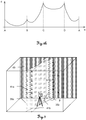
- FIGS. 5a and 5b show the course of a determination according to the invention of a vertical alignment of a laser surface on the basis of measured values to a point defined on a reference line on the basis of a predetermined emission angle.
- a measurement curve 40 shown the course of which results from detected distances d and pivot angles ⁇ when pivoting the laser surface.
- the distances may vary at different intervals eg depending on the Angle change - here in 1 ° steps - detected and assigned to the respective angles ⁇ .
- the curve shown can very quickly determine the angular position for the point with the smallest measured distance d.
- the rotating laser can pass through a swivel range of eg ⁇ 10 °, whereby only a section of the range from -8 ° to 0 ° is shown here.
- the distance d from the rotating laser to the surface at an angle ⁇ of -8 ° is 3022.2mm, decreases at -7 ° to 3015.2mm and reaches a minimum of 3000mm at -4 °.
- the measured distances d rise again up to 3007.3 mm. The smallest distance is thus detected at an angular position of - 4 ° with 3000mm.
- a laser surface can now be emitted and aligned with the surface, which can be perpendicular to the surface.
- the smallest distance d can also be determined by detecting a minimum during the recording of the measuring curve 40, eg with an increase in the measured distances d after the values have hitherto shown a decrease in the distance d, and a pivoting of the laser surface is canceled afterwards.
- the found minimum can then represent the smallest distance d of the point on the reference line to the rotation laser as a function of the angular position of the laser surface.
- the recorded readings can be further in a table, as in FIG. 5b shown, stored and assigned to each other. As a result, for example, after a selection of a certain distance d, the corresponding angle ⁇ can be approached quickly and the associated position marked on a wall.
- FIG. 6a a rotating laser 1 according to the invention is shown in a space 42 which, in contrast to the previously described embodiments, defines a laser plane 41 by means of a rotating laser beam 11.
- the laser plane 41 strikes the floor, ceiling and wall 43 of the space 42 and thus creates a continuous reference line 35. Further, the intersection points A, B, C, D of the reference line 35 are shown with the edges of the space 42.
- the laser plane 41 shown is in an indeterminate orientation relative to the wall 43.
- the inventive vertical alignment of such a laser plane 42 relative to the wall 43 is in FIG. 7 shown.
- FIG. 6b shows the course of a distance measurement along a reference line FIG. 6a
- the angular position of the rotation axis of the rotation laser is represented by the vertices A, B, C, D of the reference line.
- a user of a rotary laser according to the invention can be provided with a choice of aligning a laser surface with respect to a desired surface.
- the user may select the area between points B and C and thus the orientation perpendicular relative to the wall 43 in FIG FIG. 6a make.
- the user can also select two areas, eg the area between point B and C and the area between point D and A, in particular the areas for two walls, which are parallel to each other.
- the laser plane can be aligned such that it is perpendicular relative to the two parallel walls.
- the laser plane is aligned so that the reference line of the laser plane equidistant on both walls each having the reference line with the smallest distance to the rotating laser.
- FIG. 7 shows a further embodiment of an inventive rotary laser 1 with a clamped laser plane 41a, 41b and a respective continuous reference line 35a, 35b.
- the laser plane 41a with the generated reference line 35a is directed onto the wall 43 at a previously indeterminate angle ⁇ relative to the wall 43.
- the laser plane 41b is oriented at a 90 ° angle ⁇ relative to the wall 43 and is thus perpendicular to it.
- the distance from the rotation laser 1 to the reference line 35a can be determined in different ways and compared with each other depending on the inclination of the laser planes 41a, 41b relative to the wall 43.
- the distances to points 37 on the reference line 35a are measured at a predetermined resolution, and by comparing the distances, a minimum value corresponding to the distance to the reference line 35a is determined.
- the distances to only two points 37 can be determined, a curve of the reference line 35a can be derived from the angular position of the rotation axis of the rotation laser 1 and the distances, and mathematically a perpendicular distance to the rotation laser can be calculated, which corresponds to the distance to the reference line 35a ,
- FIG. 8 a rotating laser 1 according to the invention is shown, which is operated in an upright position.
- a laser plane 41a is defined at an indeterminate angle relative to the wall 43 by the rotating laser and generates a reference line 35a.
- the laser plane 41b is projected perpendicular relative to the wall 43.
- a vertical, in particular horizontal, alignment of laser planes 41a, 41b in spaces can take place, for example in order to generate a marking in the form of a reference line 35a, 35b on walls 43 for orientation assistance in construction measures.
- the waveform is plotted against the time axis, with the dots denoting sample and sampling points, respectively.
- the left pulse in this case represents a start pulse and the right pulse a stop pulse.
- the transit time and thus the distance Di follow, for example, from the time interval of the vertices of the two pulses, the pulses being sampled digitally similar to phase meters.
- the solution is based on the combination of two common in distance measurement basic principles for signal detection.
- the first basic principle is based on the measurement signal detection using the threshold value method and the second basic principle on the signal sampling with downstream signal processing for identification and temporal position determination of the signal.
- the signal detection is usually determined by exceeding the signal amplitude above a threshold value, but the distance-determining signal feature can take different forms available.
- the rising edge of the received signal can trigger a time trigger
- the received signal can be converted by means of an electronic filter in another suitable form to generate a trigger feature, which is advantageously independent of the pulse amplitude.
- the corresponding trigger signal is supplied as a start or stop signal to a timing circuit. Both approaches are used in parallel to the signal detection, ie, that a received pulse or a signal structure is detected with both methods, which usually implies simultaneity or at least temporal overlapping of the methods.
- the core of the principle is a lossless signal acquisition, which is lossless in the sense of preserving the term information to understand.
- the approach is based on the direct signal sampling of the received time signal in the GHz range.
- the sampling points are distributed substantially equidistantly (with respect to the time axis), wherein the distances can be maintained with an accuracy of less than 5 psec.
- the pulse can be directed from a transmitting unit to the target to be measured and passed through a receiving optics on a photodetector.
- the resulting time signal contains at least one start pulse and a stop pulse corresponding to each optically illuminated target.
- the time axis is searched for a start pulse and any stop pulses.
- the position of the pulses is thus accurately known to a sampling interval.
- the difference of the pulse positions corresponds to a first rough estimate of the distance to be determined Di.
- various hardware and software-side methods are known. For example, interpolation of up to typically one-hundredth of the time interval is possible by means of gravity analysis of the two pulses. Further methods are digital Fourier transformation (DFT) with phase evaluation or differentiation with zero-crossing determination. Preferably, evaluation methods are used which are robust to signal distortion and saturation. Here approaches from digital filter and estimation theory are often used. With such methods, eg 1 mm measuring accuracies can be achieved.
- DFT digital Fourier transformation
Landscapes
- Physics & Mathematics (AREA)
- Engineering & Computer Science (AREA)
- General Physics & Mathematics (AREA)
- Radar, Positioning & Navigation (AREA)
- Remote Sensing (AREA)
- Electromagnetism (AREA)
- Length Measuring Devices By Optical Means (AREA)
- Lasers (AREA)
Description
Die Erfindung betrifft einen Rotationslaser zur Erzeugung eines Referenzstrahls nach dem Oberbegriff des Anspruchs 1 und ein Verfahren zur Ausrichtung einer Laserfläche nach dem Oberbegriff des Anspruchs 9.The invention relates to a rotary laser for generating a reference beam according to the preamble of
Rotationslaser, die zur Markierung von Punkten oder Objekten oder zur Festlegung von Pfaden oder Referenzlinien verwendet werden, finden seit vielen Jahren im industriellen Bereich oder im Bauwesen Anwendung. Mit ihnen lassen sich horizontale, vertikale oder auch diagonale Ebenen, welche eine Hilfestellung zur Orientierung oder Positionierung an Objekten bieten, projizieren.Rotary lasers used to mark points or objects or to define paths or reference lines have been used for many years in the industrial or construction industries. They can be used to project horizontal, vertical or even diagonal planes, which offer assistance in orientation or positioning on objects.
Aufgebaut ist ein Rotationslaser zumeist aus einer rotierenden Optik, die Teil einer Lasereinheit ist und mittels derer ein Referenzlaserstrahl derart bewegt emittiert werden kann, dass ein wahrnehmbarer oder ein durch Detektoren detektierbarer Pfad bzw. eine Linie auf einer Oberfläche erzeugt wird. Damit der Pfad entsprechend definierter Vorgaben ausgerichtet werden kann, ist die Lasereinheit schwenkbar in zwei senkrecht aufeinander stehenden Richtungen relativ zu einem die Lasereinheit umgebenden Gehäuse gelagert. Zur Emission des Lasers aus dem Gehäuse heraus weist das Gehäuse zusätzlich optisch transparente Sichtfester oder Aussparungen auf.A rotating laser is usually constructed from a rotating optical system which is part of a laser unit and by means of which a reference laser beam can be emitted in such a way that a detectable path or a path detectable by detectors or a line is generated on a surface. So that the path can be aligned in accordance with defined specifications, the laser unit is mounted pivotably in two mutually perpendicular directions relative to a housing surrounding the laser unit. To emit the laser out of the housing, the housing additionally has optically transparent viewing fins or recesses.
In der
In der
Rotationslaser waren ursprünglich nicht dafür vorgesehen Distanzen zu Punkten auf jenen Oberflächen zu messen, auf welche der Laserstrahl projiziert wird. Aus dem Stand der Technik sind heute dennoch bereits Ausführungen bekannt, die einen Rotationslaser mit einer Distanzmessfunktionalität kombinieren, um z.B. mit der Projektion einer Ebene zugleich eine Entfernungsinformation zu erhalten und damit einen Grundriss eines Raumes zu generieren.Rotary lasers were originally not intended to measure distances to points on those surfaces which the laser beam is projected. However, designs are already known from the prior art today, which combine a rotary laser with a Distanzmessfunktionalität to obtain, for example, the projection of a plane at the same time a distance information and thus to generate a floor plan of a room.
In der
Im Rahmen dieses Verfahrens erfolgt in einem ersten Schritt ein Ausrichten einer Basis (X-/Y Ebene) des Markier- und/oder Nivelliergeräts zunächst senkrecht zur Oberfläche, insbesondere horizontal mittels an der Basis angeordneter Libellen. Danach erfolgt in einem zweiten Schritt ein Rotieren des Geräts um eine vertikale Achse und währenddessen ein Entfernungsmessen zur Oberfläche, wobei eine geringste Entfernung und ein zugehöriger Rotationswinkel bestimmt werden. In dieser bestimmten Winkelstellung stehen aufgrund der strukturellen Ausgestaltung des Geräts eine Gehäusefläche (Bezugsebene), aus der der punkt- oder linienförmige Projektionsstrahl austritt, in einer Startposition parallel zur Oberfläche und der Projektions- bzw. Messstrahl senkrecht zu dieser Oberfläche. Nach Ausrichten des Geräts in diese Stellung können durch ein definiertes Verschwenken der Projektionseinheit um eine Schwenkachse (welche parallel zur Oberfläche und horizontal verläuft) nun im Anschluss an die vorgenommene Geräteausrichtung Linien oder Punkte in bestimmten Abständen auf die Oberfläche projiziert werden.In the context of this method, in a first step, a base (X / Y plane) of the marking and / or leveling device is aligned initially perpendicular to the surface, in particular horizontally by means of dragonflies arranged on the base. Thereafter, in a second step, the device is rotated about a vertical axis and during this time a distance measurement to the surface, wherein a smallest distance and an associated rotation angle are determined. In this particular angular position are due to the structural configuration of the device, a housing surface (reference plane) from which emerges the point or line-shaped projection beam, in a start position parallel to the surface and the projection or measuring beam perpendicular to this surface. After the device has been aligned in this position, a defined pivoting of the projection unit about a pivot axis (which runs parallel to the surface and horizontally) can now be used to project lines or points onto the surface at specific intervals following the alignment of the device.
Eine genaue Ausrichtung einer Laserebene bzw. einer Laserfläche relativ zu einer Oberfläche, insbesondere senkrecht zu einer Oberfläche, kann bei den bisher bekannten Rotationslasern nur durch eine Positionsänderung des Lasers selbst oder etwa durch ein manuell gesteuertes Schwenken der emittierten Laserfläche erfolgen. Dadurch kann das exakte Ausrichten nur mit einem hohen Zeitaufwand erreicht werden und ist darüber hinaus nur bedingt genau, im Rahmen der Genauigkeit des Augenmasses des Benutzers, durchführbar. Die Möglichkeit diese Ausrichtung einfach und schnell vornehmen zu können besteht weiterhin nur für gut ausgebildete, erfahrene oder hoch qualifizierte Benutzer, da dabei viele Details zu berücksichtigen sind. Eine Benutzerfreundlichkeit bei der Ausrichtung der Laserfläche ist somit nicht gegeben. Unter diesen Umständen kann sich für den durchschnittlichen Benutzer eines Rotationslasers das Ausrichten zu einem aufwändigen und komplizierten Prozess entwickeln. Darüber hinaus kann eine eingestellte Ausrichtung der Laserfläche durch Störungen in der Lage des Rotationslasers, z.B. durch ein unbeabsichtigtes Anstossen an den Laser, nicht zuverlässig genau eingehalten werden. Der Erfindung liegt folglich die Aufgabe zugrunde, einen verbesserten Rotationslaser zum genauen und zuverlässigen senkrechten Ausrichten einer Laserfläche relativ zu einer Oberfläche bereitzustellen, wobei dieses Ausrichten schnell, einfach und benutzerfreundlich ermöglicht wird. Eine weitere spezielle Aufgabe der Erfindung ist es eine senkrechte Projektion einer Laserfläche relativ zu einer Oberfläche in vertikaler oder horizontaler Richtung zu erzeugen.A precise alignment of a laser plane or a laser surface relative to a surface, in particular perpendicular to a surface, can be carried out in the previously known rotary lasers only by a change in position of the laser itself or by a manually controlled pivoting of the emitted laser surface. As a result, the exact alignment can only be achieved with a high expenditure of time and, moreover, is only conditionally accurate, within the scope of the accuracy of the user's judgment. The ability to make this alignment easy and fast is still only for well-trained, experienced or highly qualified users, as many details have to be considered. A user-friendliness when aligning the laser surface is therefore not given. Under these circumstances, for the average user of a rotary laser, aligning can become a cumbersome and complicated process. In addition, a set alignment of the laser surface due to disturbances in the position of the rotary laser, for example by accidental impact against the laser, can not be reliably maintained accurately. It is therefore an object of the present invention to provide an improved rotary laser for accurately and reliably perpendicularly aligning a laser surface relative to a surface, which alignment is made quick, easy and user-friendly. Another specific object of the invention is a perpendicular projection of a laser surface relative to a Surface in vertical or horizontal direction to produce.
Diese Aufgaben werden durch die Verwirklichung der kennzeichnenden Merkmale der unabhängigen Ansprüche gelöst. Merkmale, die die Erfindung in alternativer oder vorteilhafter Weise weiterbilden, sind den abhängigen Patentansprüchen zu entnehmen.These objects are achieved by the realization of the characterizing features of the independent claims. Features which further develop the invention in an alternative or advantageous manner can be found in the dependent claims.
Entsprechend der Erfindung weist ein Rotationslaser eine Laserstrahlquelle auf, aus welcher ein sichtbarer oder ein mittels eines Detektors nachweisbarer Laserstrahl emittiert wird. Dieser Laserstrahl wird unter Verwendung von motorisierten Umlenkmitteln wie z.B. Umlenkspiegeln abgelenkt und als Referenzstrahl verwendet, durch dessen Bewegung - verursacht durch jene Umlenklenkspiegel - ein Referenzpfad auf einer Oberfläche erzeugt wird. Zusätzlich sind Mittel zur Abstands- bzw. Entfernungsmessung zu Punkten auf der Oberfläche unter Verwendung des Referenzstrahls vorgesehen.According to the invention, a rotating laser comprises a laser beam source from which a visible or detectable by means of a detector laser beam is emitted. This laser beam is generated using motorized deflection means such as e.g. Deflecting deflecting mirrors and used as a reference beam, by the movement of which - caused by those deflecting mirror - a reference path is generated on a surface. In addition, means are provided for measuring the distance to points on the surface using the reference beam.
Mit dieser Anordnung wird der Referenzpfad auf eine Oberfläche projiziert, wobei durch den Referenzpfad eine Laserfläche definiert wird und dabei insbesondere eine Line auf der Oberfläche erzeugt wird. Zum Ausführen einer erfindungsgemässen Funktion zum Ausrichten der Laserfläche kann sich der Rotationslaser hierbei insbesondere in einer liegenden Position befinden, sodass sich die Projektion z.B. in einem Raum über Boden, Wände und Decke erstreckt, insbesondere wobei der Rotationslaser dafür derart positioniert sein kann, dass die Laserfläche vor Ausführen der Funktion bereits grob senkrecht relativ zur Wand ausgerichtet ist. Mit starten der Funktion wird die Laserfläche jetzt innerhalb eines Winkelbereichs über die Wand bewegt und damit die Neigung der Laserfläche relativ zur Oberfläche der Wand verändert. Währenddessen wird ein Abstand vom Rotationslaser zur jeweiligen Referenzlinie auf der Oberfläche fortlaufend gemessen. Das Neigen der Laserfläche kann durch ein Schwenken eines Teils des Rotationslasers, der die Umlenkmittel umfasst, erfolgen oder durch eine schwenkende Bewegung der Umlenkspiegel selbst. Zusätzlich können die jeweiligen Abstandsdaten und die Werte für die Winkelstellung der Umlenkmittel zu jeder Messung gespeichert und einander zugeordnet werden. Nachdem der Winkelbereich durchfahren ist werden die gespeicherten Abstände zur Referenzlinie miteinander verglichen und der geringste Abstandswert definiert. Anschliessend wird unter Verwendung der gespeicherten Winkelwerte die Laserebene bzw. eine Laserfläche so projiziert, dass diese durch jene Referenzlinie verläuft, für die der geringste Abstand bestimmt wurde. Dabei kann zusätzlich berücksichtigt werden, dass die Projektion nicht am Rand des vorher definierten Winkelbereichs verläuft sondern sich innerhalb der Grenzen des Winkelbereichs befindet. Mit der Erfüllung dieser Bedingung erhält man eine Projektion einer Laserlinie oder Laserfläche auf einer Wand, die relativ zu dieser senkrecht steht und damit den geringsten Abstand der Strahlungsquelle zur Wand aufweist.With this arrangement, the reference path is projected onto a surface, wherein a laser surface is defined by the reference path and in particular a line is generated on the surface. For carrying out a function according to the invention for aligning the laser surface, the rotary laser can be in a lying position in particular, so that the projection extends, for example, in a room over the floor, walls and ceiling, in particular where the rotary laser can be positioned such that the laser surface is already aligned roughly perpendicular to the wall before performing the function. With the start of the function, the laser surface is now within an angular range over the Moves wall and thus changes the inclination of the laser surface relative to the surface of the wall. Meanwhile, a distance from the rotating laser to the respective reference line on the surface is continuously measured. The tilting of the laser surface may be accomplished by pivoting a portion of the rotating laser comprising the deflection means or by pivoting the deflection mirror itself. In addition, the respective distance data and angular position values of the deflection means may be stored and associated with each measurement. After passing through the angle range, the stored distances to the reference line are compared with each other and the smallest distance value is defined. Subsequently, using the stored angle values, the laser plane or a laser surface is projected so that it passes through the reference line for which the smallest distance was determined. In this case, it can additionally be taken into account that the projection does not run along the edge of the previously defined angular range but is within the limits of the angular range. With the fulfillment of this condition, one obtains a projection of a laser line or laser surface on a wall which is perpendicular relative to this and thus has the smallest distance of the radiation source to the wall.
Im Unterschied zu anderen bekannten Rotationslasern und deren Projektionsverfahren wird mit der vorliegenden Ausführung ein System bereitgestellt, mit welchem nicht nur eine vertikale oder horizontale Laserlinie auf eine Oberfläche projiziert werden kann, sondern die Projektion einer Laserfläche automatisch so ausgerichtet werden kann, dass sie - wie beschriebenen - senkrecht relativ zu der Oberfläche steht.In contrast to other known rotary lasers and their projection methods, the present embodiment provides a system with which not only a vertical or horizontal laser line can be projected onto a surface, but the projection of a laser surface can be automatically aligned so that it - as described - is perpendicular relative to the surface.
Mit der vorliegenden Erfindung kann das Ausrichten ausserdem zuverlässig und automatisiert erfolgen, wobei weiterhin die resultierende senkrechte Positionierung der Laserfläche relativ zur Oberfläche eine hohe Genauigkeit aufweist. Vorteilhaft ist zusätzlich, dass das Ausrichten einfach durchgeführt und eine hohe Benutzerfreundlichkeit erreicht werden kann, indem das Ausrichten beispielsweise auf Knopfdruck ausgeführt wird und darüber hinaus kaum weiteres Vorwissen nötig ist. Eine hohe Robustheit gegenüber äusseren Einflüssen ist darüber hinaus dadurch gegeben, dass die Ausrichtfunktion kontinuierlich erfolgen kann und damit z.B. Erschütterungen des Rotationslaser oder Stösse, die zu Änderungen der Ausrichtung des Lasers zur Oberfläche führen können, automatisch ausgeglichen werden. Die einfache und schnelle Wiederholbarkeit der automatisierten Ausrichtung ist ein weiterer Vorteil der Erfindung.With the present invention, the alignment can also be done reliably and automatically, and furthermore the resulting vertical positioning of the laser surface relative to the surface has a high accuracy. It is also advantageous that the alignment can be performed easily and a high level of user-friendliness can be achieved by the alignment is performed, for example, at the touch of a button and beyond hardly any further knowledge is needed. In addition, a high degree of robustness against external influences is given by the fact that the alignment function can be carried out continuously and thus, for Vibrations of the rotating laser or bumps, which can lead to changes in the orientation of the laser to the surface, are automatically compensated. The easy and fast repeatability of the automated alignment is another advantage of the invention.
Zur Bestimmung der Referenzlinie mit dem geringsten Abstand zum Rotationslaser kann alternativ auf ein komplettes Durchfahren des Winkelbereichs und ein Vergleichen der dabei gemessenen Abstände teilweise verzichtet werden und dafür ein kontinuierliches Vergleichen der Abstände erfolgen, wobei beim Durchschreiten eines Abstandminimums, d.h. sobald die bisher abnehmenden Abstandswerte wieder zunehmen, der Vorgang unterbrochen und das somit festgestellte Minimum die Position der Referenzlinie mit dem geringsten Abstand zum Rotationslaser repräsentiert.Alternatively, to determine the reference line with the smallest distance to the rotating laser, it is possible to dispense with completely passing through the angular range and comparing the distances measured in the process and to make a continuous comparison of the distances, whereby when passing through a distance minimum, i. as soon as the previously decreasing distance values increase again, the process is interrupted and the thus determined minimum represents the position of the reference line with the smallest distance to the rotation laser.
Das Schwenken der Laserfläche kann durch ein Laser-Core-Modul erfolgen, welches eine Laserstrahlquelle und drehbare Umlenkmittel zum Führen des Laserstrahls aufweist, wobei der Laserstrahl parallel zu einer Rotationsachse der Umlenkmittel gerichtet ist und beim Auftreffen auf das Umlenkmittel abgelenkt wird. Das komplette Modul ist zusätzlich um mindestens eine Achse schwenkbar relativ zum Gehäuse des Rotationslasers und erlaubt somit ein Ausrichten des emittierten Laserstrahls. Das Gehäuse des Rotationslasers verbleibt bei einer Schwenkbewegung des Moduls in seiner ursprünglichen Position.The pivoting of the laser surface may be effected by a laser core module, which has a laser beam source and rotatable deflection means for guiding the laser beam, wherein the laser beam is directed parallel to an axis of rotation of the deflection means and when hitting the Deflection is deflected. The complete module is additionally pivotable about at least one axis relative to the housing of the rotary laser and thus allows an alignment of the emitted laser beam. The housing of the rotary laser remains at a pivotal movement of the module in its original position.
Im Falle einer Positionierung des Rotationslasers derart, dass mit dem Durchfahren des Schwenkbereichs bzw. Winkelbereichs die kleinsten Abstände für Punkte auf der Grenze des Winkelbereichs bestimmt werden, kann der Rotationslaser auch durch ein Bewegen des Laser-Core-Moduls eine zusätzlich notwendige Grobjustierung vornehmen, sodass der abgefahrene Bereich auf der Wand verändert wird und nach der Justierung ein Bereich auf der Wand abgedeckt werden kann, welcher die Referenzlinie mit dem jeweils geringsten Abstand aufweist. Eine hierfür erforderliche Positionierung des Rotationslasers relativ zur Wand kann darüber hinaus - oder alternativ - auch manuell durchgeführt werden.In the case of a positioning of the rotary laser such that the smallest distances for points on the boundary of the angular range are determined by passing through the pivoting range or angle range, the rotating laser can also make an additional necessary coarse adjustment by moving the laser core module the worn area on the wall is changed and after the adjustment, an area on the wall can be covered, which has the reference line with the shortest distance. A required positioning of the rotary laser relative to the wall can also - or alternatively - be carried out manually.
Weiterhin kann die Abstandsbestimmung der Referenzlinie auf unterschiedliche Arten durchgeführt werden. Zum einen kann ein relativer Abstand der einzelnen Referenzlinien zueinander bestimmt werden, indem für jede Linie der Abstand zu einem Punkt auf der Linie bestimmt wird, wobei die Lage des Punktes auf der Linie durch einen für alle Messungen gleich bleibenden Emissionswinkel des Laserstrahls bezüglich der Rotationsachse des Rotationslasers vorbestimmt ist und ein Schwenken einer Laserfläche in senkrechter Richtung relativ zu dieser erfolgt. Dadurch erhält man Abstandswerte, welche miteinander vergleichbar sind, mit welchen ein Abstandsminimum bestimmt werden kann und womit ein senkrechtes Ausrichten der Laserfläche relativ zur Oberfläche erfolgen kann. Die somit ermittelten Abstände entsprechen jedoch nicht den absoluten Abständen, d.h. den winkelabhängig geringsten Abständen, der Referenzlinien zum Rotationslaser. Zur Ermittlung dieser Absolutabstände können zunächst die Abstände zu mindestens zwei Punkten auf der Referenzlinie bei einem festgehaltenen Schwenkwinkel gemessen werden und aus den zugehörigen Emissionswinkeln und den gemessenen Abstandswerten der Verlauf der Referenzlinie abgeleitet werden. Ein Schwenken der Laserfläche in senkrechter Richtung zu dieser ist in diesem Fall nicht erforderlich. Die Bestimmung des absoluten Abstandes lässt sich dann mathematisch aus diesem Verlauf ableiten, indem eine Gerade, die senkrecht auf der Referenzlinie steht und durch den Rotationslaser verläuft, berechnet und die Strecke vom Laser zum Schnittpunkt der Geraden mit der Oberfläche bestimmt wird. Alternativ dazu kann eine grössere Anzahl von Abständen zu Punkten auf der Referenzlinie mit einer vorbestimmten Auflösung, wiederum für jeweils einen gemeinsamen festgehaltenen Schwenkwinkel, gemessen werden. Durch einen Vergleich dieser Abstände kann wiederum ein minimaler Abstandswert bestimmt werden, welcher einem Absolutabstand zur Referenzlinie entspricht. Bei einer hohen Auflösung von Messpunkten kann ein direktes Bestimmen des Punktes mit dem geringsten Abstand erfolgen, ist jedoch eine grobe Auflösung der Messpunkte vorgesehen, so kann der Minimalabstand durch ein Berechnen, z.B. mittels Ausgleichsrechnung bzw. Regression, einer die Abstände und Emissionswinkel repräsentierende Funktion bestimmt werden, indem ein Minimum dieser Funktion bestimmt wird.Furthermore, the distance determination of the reference line can be performed in different ways. On the one hand, a relative distance of the individual reference lines from one another can be determined by determining the distance to a point on the line for each line, the position of the point on the line being determined by a constant emission angle of the laser beam with respect to the axis of rotation of the laser beam Rotation laser is predetermined and a pivoting of a laser surface in the vertical direction relative to this takes place. This gives distance values which are comparable with one another, with which a minimum distance can be determined and with what vertical alignment of the laser surface relative to the surface can be done. However, the distances thus determined do not correspond to the absolute distances, ie the angle-dependent smallest distances, the reference lines to the rotating laser. To determine these absolute distances, the distances to at least two points on the reference line at a fixed pivot angle can first be measured, and the course of the reference line can be derived from the associated emission angles and the measured distance values. A pivoting of the laser surface in the direction perpendicular to this is not required in this case. The determination of the absolute distance can then be derived mathematically from this course by a straight line, which is perpendicular to the reference line and passes through the rotating laser, calculated and the distance from the laser to the intersection of the line with the surface is determined. Alternatively, a greater number of distances to points on the reference line may be measured at a predetermined resolution, again for each one common retained swing angle. By comparing these distances, in turn, a minimum distance value can be determined, which corresponds to an absolute distance to the reference line. With a high resolution of measuring points, a direct determination of the point with the smallest distance can take place, but if a coarse resolution of the measuring points is provided, the minimum distance can be determined by calculating, for example by means of compensation calculation or regression, a function representing the distances and emission angles by determining a minimum of this function.
Zur Verbesserung der Genauigkeit bei der Ausrichtung der Laserfläche können die Werte der Abstandsmessungen und ein dazu gehörigen Emissionswinkel der Laserfläche zum Rotationslaser miteinander verknüpft, angehäuft und aus diesen Mittelwerte abgeleitet werden, sodass die Positionen des Punktes mit dem kleinsten Abstand zur Wand bzw. zur Oberfläche genauer bestimmt werden kann.In order to improve the accuracy of the alignment of the laser surface, the values of the distance measurements and an associated emission angle of the laser surface to the rotating laser can be linked, accumulated and derived from these averages, so that the positions of the point with the smallest distance to the wall or to the surface more accurate can be determined.
In einer speziellen Ausführung kann an dem Rotationslaser ein Neigungssensor vorgesehen sein, damit die Referenzlinie parallel zum Schwerefeld der Erde geführt und in dieser Ausrichtung innerhalb des definierten Winkelbereichs bewegt werden kann. Unter dieser Voraussetzung wird jetzt wieder der Abstand zu einem festen Punkt auf dem Referenzpfad gemessen und gespeichert und nach der Bestimmung jenes Punktes mit dem kleinsten Abstand eine zum Schwerefeld parallele Referenzlinie bzw. Laserfläche durch diesen Punkt projiziert, die wiederum innerhalb der Grenzen des Winkelbereichs liegt, dadurch senkrecht relativ zur Wand projiziert ist und den kürzesten Abstand von der Strahlungsquelle zur Wand repräsentiert. Damit wird eine nicht nur relativ zur Oberfläche senkrechte, sondern auch vertikal verlaufende Laserfläche erzeugt.In a special embodiment, an inclination sensor can be provided on the rotating laser so that the reference line can be guided parallel to the gravitational field of the earth and moved in this orientation within the defined angular range. Under this condition, the distance to a fixed point on the reference path is now again measured and stored and, after the determination of that point with the smallest distance, a reference plane or laser surface parallel to the gravity field is projected through this point, which in turn lies within the limits of the angular range. is thereby projected perpendicular relative to the wall and represents the shortest distance from the radiation source to the wall. This produces a laser surface which is not only perpendicular to the surface but also extends vertically.
Insbesondere kann eine Laserebene auch relativ zu zwei Oberflächen gleichzeitig ausgerichtet werden. Hierfür können beispielsweise zwei gegenüberliegende Wände ausgewählt werden, auf welche die Ebene projiziert wird und auf welchen jeweils der Abstand zu einer Referenzlinie, die jeweils durch die Laserebene definiert ist, bestimmt wird. Verlaufen diese Wände parallel zueinander, so kann die Laserebenen derart ausgerichtet werden, dass auf jeder Wand die Referenzlinie mit dem kleinsten Abstand zum Rotationslaser in der Ebene liegt und diese damit relativ zu beiden Wänden senkrecht steht. Weicht der Verlauf der beiden Wände aber von einer parallelen Ausrichtung ab, so können wiederum zu jeder Wand diejenige Referenzlinien ermittelt werden, welche die geringste Entfernung zum Rotationslaser haben, und entsprechende Neigungswinkel erfasst werden. Anschliessend kann die Laserebene so ausgerichtet werden, dass der Neigungswinkel der Ebene einem mittleren Neigungswinkel zwischen den zu den beiden Wänden bestimmten Winkeln entspricht. Auf diese Weise erhält man die Projektion einer Laserebene, die eine Art gemeinsame Ausgleichsebene zu beiden Wänden darstellt und dabei einen bestimmten Winkel ungleich 90° relativ zu den Wänden aufweist.In particular, a laser plane can also be aligned simultaneously relative to two surfaces. For this purpose, for example, two opposite walls can be selected, on which the plane is projected and on each of which the distance to a reference line, which is defined by the laser plane, is determined. If these walls run parallel to one another, then the laser planes can be aligned in such a way that the reference line with the smallest distance to the rotation laser lies in the plane on each wall, and thus relative thereto is perpendicular to both walls. However, if the course of the two walls deviates from a parallel orientation, it is again possible to determine for each wall those reference lines which have the smallest distance to the rotary laser and corresponding inclination angles are detected. Subsequently, the laser plane can be aligned so that the angle of inclination of the plane corresponds to an average angle of inclination between the angles determined to the two walls. In this way one obtains the projection of a laser plane, which represents a kind of common compensation plane to both walls and thereby has a certain angle other than 90 ° relative to the walls.
Weiterhin können die Positionen der Punkte oder der Verlauf des Referenzpfades in ein externes Koordinatensystem übertragen werden, wobei die Winkelstellungen der Umlenkmittel bzw. der Umlenkspiegel, die Neigung der Laserebene und des Rotationslasers und der Abstand zu einem Punkt bzw. zu allen Punkten auf dem Referenzpfad berücksichtig werden.Furthermore, the positions of the points or the course of the reference path can be transmitted to an external coordinate system, wherein the angular positions of the deflection or the deflection mirror, the inclination of the laser plane and the rotation laser and the distance to a point or to all points on the reference path taken into account become.
Zur Verdeutlichung werden im Folgenden Ausführungsformen des erfindungsgemässen Rotationslasers und des Verfahrens zur Ausrichtung der Laserfläche mit anderen Worten alternativ beschrieben.For the sake of clarity, embodiments of the inventive rotary laser and the method for aligning the laser surface will be described below in other words.
Ein erfindungsgemässer Rotationslaser weist eine Quelle elektromagnetischer Strahlung, insbesondere eine Laserstrahlquelle, zur Erzeugung eines Referenzstrahls und um eine Rotationsachse drehbare Umlenkmittel zum rotierenden Aussenden des Referenzstrahls, wodurch eine Laserfläche definiert wird und wobei der Referenzstrahl einen Referenzpfad durchläuft und mindestens ein Teil des Referenzpfades als Referenzlinie visuell und/oder mittels eines Detektors auf einer Oberfläche wahrnehmbar ist. Weiter sind Schwenkmitteln zum Schwenken der Rotationsachse um mindestens eine Achse, insbesondere um zwei Achsen, und eine Entfernungsmesseinheit zum Messen von Entfernungen zu Punkten auf dem Referenzpfad vorgesehen. Zusätzlich weist der Rotationslaser Steuerungsmittel zur Steuerung der Schwenkmittel und zum Vergleichen von Entfernungen auf.A rotating laser according to the invention has a source of electromagnetic radiation, in particular a laser beam source, for generating a reference beam and deflecting means rotatable about a rotation axis for rotating the reference beam, thereby defining a laser surface and wherein the reference beam passes through a reference path and at least a part of the reference beam Reference path is visible as a reference line visually and / or by means of a detector on a surface. Further, pivot means are provided for pivoting the axis of rotation about at least one axis, in particular about two axes, and a distance measuring unit for measuring distances to points on the reference path. In addition, the rotary laser has control means for controlling the pivot means and for comparing distances.
Erfindungsgemäss ist der Rotationslaser mit einer Funktionalität zum senkrechten Ausrichten der Laserfläche relativ zu der Oberfläche versehen, wobei die Steuerungsmittel derart ausgebildet sind, dass automatisch ein variierendes Neigen der Laserfläche relativ zur Oberfläche durch Schwenken der Rotationsachse erfolgt. Zu jeweiligen Neigungswinkeln erfolgt jeweils ein Bestimmen einer Referenzlinienentfernung der Referenzlinie zum Rotationslaser und weiter ein Bestimmen jenes Neigungswinkels der Laserfläche als Senkrecht-Neigungswinkel, bei welchem die Laserfläche die Referenzlinie mit der jeweils geringsten bestimmten Referenzlinienentfernung beinhaltet und damit senkrecht relativ zur Oberfläche steht.According to the invention, the rotary laser is provided with a functionality for perpendicularly aligning the laser surface relative to the surface, wherein the control means are designed such that automatically a varying inclination of the laser surface relative to the surface takes place by pivoting the axis of rotation. At respective angles of inclination, a reference line distance of the reference line to the rotation laser is determined in each case, and furthermore a determination of that angle of inclination of the laser surface as the vertical inclination angle at which the laser surface contains the reference line with the respective smallest determined reference line distance and thus is perpendicular relative to the surface.
Insbesondere kann im Rahmen der Funktionalität zusätzlich ein Einstellen des Neigungswinkels der Laserfläche auf den Senkrecht-Neigungswinkel erfolgen.In particular, within the scope of the functionality, an adjustment of the inclination angle of the laser surface to the vertical inclination angle can additionally be carried out.
Insbesondere kann im Rahmen einer Weiterbildung der Funktionalität ein Ausrichten einer Laserfläche relativ zu einer ersten und einer der ersten gegenüberliegenden zweiten Oberfläche wie folgt erfolgt. Beim variierenden Neigen der Laserfläche werden Referenzlinienentfernungen zu auf der ersten und zweiten Oberfläche liegenden Referenzlinien bestimmt, für die erste und zweite Oberfläche erfolgt das Bestimmen zweier Neigungswinkel der Laserfläche als erster und zweiter Senkrecht-Neigungswinkel, bei welchen die Laserfläche jeweils eine erste und zweite Referenzlinie mit einer jeweils ersten und zweiten geringsten bestimmten Referenzlinienentfernung beinhaltet und damit senkrecht relativ zur ersten und/oder zweiten Oberfläche steht, und es erfolgt ein Einstellen des Neigungswinkels der Laserfläche auf einen mittleren, insbesondere arithmetisch gemittelten, Neigungswinkel zwischen dem ersten und zweiten Senkrecht-Neigungswinkel. Insbesondere können weiter die Neigungswinkel und die dabei jeweils bestimmten Referenzlinienentfernungen miteinander zu Wertepaaren verknüpft und in einer Datenbank, insbesondere in einer Tabelle, gespeichert werden. Ausserdem kann eine Entfernungsmessung im Rahmen der Erfindung zumindest mit Teilen des an der Oberfläche reflektierten Referenzstrahls erfolgen.In particular, as part of a further development of functionality, alignment of a laser surface relative to a first and one of the first opposing second surfaces takes place as follows. With the varying tilt of the laser surface, reference line distances become to the first and second surfaces Reference lines determines, for the first and second surface, the determination of two inclination angles of the laser surface as the first and second perpendicular inclination angle, in which the laser surface each includes a first and second reference line having a first and second lowest determined reference line distance and thus perpendicular relative to the first and / or second surface, and adjusting the inclination angle of the laser surface to a mean, in particular arithmetically averaged, inclination angle between the first and second perpendicular inclination angles. In particular, the inclination angle and the particular reference line distances determined in each case can be linked to value pairs and stored in a database, in particular in a table. In addition, a distance measurement in the context of the invention can take place at least with parts of the reference beam reflected on the surface.
Darüber hinaus kann der Rotationslaser Mittel zum Bestimmen eines Emissionswinkels des Referenzstrahls anhand einer Stellung der Führungsmittel aufweisen. Zusätzlich können Messwerte für die Entfernungen zu Punkten in definierten Emissionswinkeln angehäuft und ein Durchschnittswert für gemessene Entfernungen ermittelt werden. Dadurch kann eine Steigerung der Genauigkeit bei der Bestimmung von Entfernungen zu Punkten erreicht werden und damit einhergehend ein Ausrichten der Laserebene exakter erfolgen. Erfindungsgemäss erfolgt das Bestimmen der Entfernung der Referenzlinie zum Rotationslaser durch ein Messen von Entfernungen und Bestimmen von Emissionswinkeln zu mindestens zwei Punkten auf der Referenzlinie. Zusätzlich wird dabei aus den Entfernungen und den Emissionswinkeln ein Verlauf der Referenzlinie abgeleitet und mathematisch eine kürzeste Strecke von Rotationslaser zu Referenzlinie berechnet, die als die Referenzlinienentfernung zum Rotationslaser berücksichtigt wird.In addition, the rotary laser may comprise means for determining an emission angle of the reference beam based on a position of the guide means. In addition, measured values for the distances to points in defined emission angles can be accumulated and an average value for measured distances can be determined. As a result, an increase in the accuracy in the determination of distances to points can be achieved and, consequently, an alignment of the laser plane can be carried out more accurately. In accordance with the invention, determining the distance of the reference line to the rotating laser is accomplished by measuring distances and determining emission angles to at least two points on the reference line. In addition, a course of the reference line is derived from the distances and the emission angles, and mathematically a shortest distance from the rotation laser to the reference line is calculated, which is taken into account as the reference line distance to the rotation laser.
Insbesondere kann das Bestimmen der Entfernung der Referenzlinie zum Rotationslaser auch durch ein Messen von Entfernungen und Bestimmen von Emissionswinkeln zu einer Vielzahl von Punkten auf der Referenzlinie mit einer vorbestimmten Auflösung, insbesondere mit einer Auflösung von 5-50 Punkten pro 10° Winkeländerung der Umlenkmittel, erfolgen. Hierbei kann durch ein Vergleichen von Entfernungen zu den Punkten eine minimale Entfernung bestimmt werden, insbesondere wobei eine minimale Entfernung durch ein Berechnen eines Minimums einer die Entfernungen und Emissionswinkel repräsentierenden Funktion bestimmt wird, die als die Referenzlinienentfernung zum Rotationslaser berücksichtigt wird.In particular, determining the distance of the reference line to the rotating laser can also be done by measuring distances and determining emission angles to a plurality of points on the reference line with a predetermined resolution, in particular with a resolution of 5-50 points per 10 ° angle change of the deflection means , Here, by comparing distances to the points, a minimum distance can be determined, particularly where a minimum distance is determined by calculating a minimum of a function representing the distances and emission angles taken into account as the reference line distance to the rotation laser.
Ausserdem kann das variierende Neigen der Laserfläche für das Bestimmen der geringsten Referenzlinienentfernung zum Rotationslaser solange erfolgen, bis in einem Verlauf einer dabei aufgenommenen Messkurve ein Minimum festgestellt wird.In addition, the varying inclination of the laser surface for determining the smallest reference line distance to the rotating laser can be carried out until a minimum is determined in the course of a recorded measurement curve.
Weitergehend kann der Rotationslaser ein Laser-Core-Modul mit einer Laserstrahlquelle und mit den um die Rotationsachse drehbaren Umlenkmitteln, die als Führungsmittel für einen Laserstrahl vorgesehen sind, aufweisen, wobei der Laserstrahl parallel zur Rotationsachse emittiert und das Laser-Core-Modul um mindestens eine Achse, insbesondere um zwei Achsen, schwenkbar ist. Mit dieser Ausführungsform ist eine Grobausrichtung des Rotationslasers vor Ausführen der Funktionalität nicht erforderlich, sondern kann durch das bewegliche Modul durchgeführt werden.Furthermore, the rotary laser can have a laser core module with a laser beam source and with the deflection means which are rotatable about the rotation axis and which are provided as a guide means for a laser beam, the laser beam emitting parallel to the axis of rotation and the laser core module at least one Axis, in particular about two axes, is pivotable. With this embodiment, a coarse alignment of the rotary laser prior to performing the functionality is not required, but may be performed by the movable module.
Zusätzlich kann die Ausrichtung des Rotationslasers relativ zum Schwerefeld mit einem Neigungsmesser erfasst werden und die Laserfläche parallel zum Schwerefeld ausgerichtet werden. Diese beiden Schritte können vor Ausführung der Funktionalität erfolgen und bewirken eine vertikale Ausrichtung der Laserfläche und eine schliesslich senkrechte Ausrichtung relativ zur Oberfläche.In addition, the orientation of the rotating laser relative to the gravitational field can be detected with an inclinometer and the laser surface aligned parallel to the gravitational field. These two steps can be done before the functionality is performed and cause a vertical alignment of the laser surface and finally a vertical orientation relative to the surface.
Bezüglich des Ausrichtens der Rotationsachse bzw. der Laserfläche kann erfindungsgemäss somit die Rotationsachse bzw. die Laserebene mittels der Schwenkmittel automatisch horizontal oder vertikal ausgerichtet werden, insbesondere wobei das horizontale oder vertikale Ausrichten der Rotationsachse in Abhängigkeit von einem Messwert eines Neigungssensors erfolgt.With regard to the alignment of the axis of rotation or the laser surface, according to the invention, therefore, the axis of rotation or the laser plane can be automatically aligned horizontally or vertically by means of the pivoting means, in particular with horizontal or vertical alignment of the axis of rotation as a function of a measured value of a tilt sensor.
Die Entfernungsmessung mit dem erfindungsgemässen Rotationslaser betreffend kann erfindungsgemäss die Entfernungsmesseinheit eine Emissionseinheit und eine Empfangseinheit aufweisen und derart ausgebildet sein, dass zur Entfernungsmessung eine Emission und ein Empfangen eines Messstrahls in jeweils paralleler Richtung, insbesondere koaxial, erfolgen, insbesondere wobei die Entfernungsmessung mittels Wellenform-Digitalisierung (WFD; wie zu
Zusätzlich zu einer einen Referenzstrahl emittierenden Laserstrahlquelle kann eine zweite Strahlquelle ebenfalls zur Erzeugung einer Laserstrahlung vorgesehen sein, die dafür geeignet ist, insbesondere nach einer Reflexion von einer Oberfläche, von einem Empfänger detektiert zu werden und damit die Ermittelung einer Entfernung von Strahlquelle zu Oberfläche präzise durchführbar macht. Die beiden Strahlen können zudem gemeinsam, parallel zueinander versetz oder koaxial geführt werden, um eine Entfernungsmessung an jeweils dem Punkt durchführen zu können, der durch den Referenzstrahl definiert wird.In addition to a laser beam source emitting a reference beam, a second beam source may also be provided for generating a laser radiation suitable for being detected by a receiver, particularly after reflection from a surface, and thereby accurately determining a distance from beam source to surface power. In addition, the two beams can be jointly displaced parallel to one another or guided coaxially in order to be able to carry out a distance measurement at the point which is defined by the reference beam.
Ein weiterer Aspekt der Erfindung betrifft eine Projektion von Referenzlinien auf eine Oberfläche, wobei die Referenzlinien dabei so projiziert werden können, dass ein erster Abstand zwischen jeweils zwei benachbarten Linien gleich gross bzw. identisch mit einem zweiten Abstand von zwei anderen, benachbarten Linien ist. Ferner können der Abstand zwischen den Referenzlinien mittels einer definierten Variation des Neigungswinkels für die Rotationsachse bzw. die Laserfläche präzise eingestellt und somit parallel versetzte Linien erzeugt werden. Eine derartige Projektion basiert auf einem erfindungsgemässen senkrechten Ausrichten der Laserfläche zur Oberfläche und den dabei vorgenommenen Messungen bzw. ermittelten Messwerten (Winkeln und Entfernungen) an der Oberfläche. Aus der in diesem Zusammenhang erzeugbaren Verknüpfung von Entfernungsmesswerten und jeweiligen Neigungswinkeln kann die Projektion an definierter Position und mit bestimmten Abständen der Linien auf der Oberfläche erfolgen. Erfindungsgemäss kann dabei somit mindestens ein erster und ein zweiter Projektions-Neigungswinkel für die Neigung der Laserfläche derart einstellbar sein, dass ein definierter Abstand zwischen den bei den mindestens zwei Projektions-Neigungswinkeln auf der Oberfläche erzeugten Referenzlinien vorliegt, insbesondere wobei eine Vielzahl von Projektions-Neigungswinkeln einstellbar ist und die Abstände zwischen jeweils zwei benachbarten, dadurch auf der Oberfläche erzeugten Referenzlinien identisch bzw. gleich gross sind.Another aspect of the invention relates to a projection of reference lines on a surface, wherein the reference lines can be projected so that a first distance between each two adjacent lines is the same size or identical to a second distance from two other, adjacent lines. Furthermore, the distance between the reference lines can be set precisely by means of a defined variation of the inclination angle for the axis of rotation or the laser surface, and thus lines offset in parallel can be generated. Such a projection is based on an inventive vertical alignment of the laser surface to the surface and the measurements made or determined measured values (angles and distances) on the surface. From the combination of distance measurement values and respective angles of inclination that can be generated in this context, the projection can take place at a defined position and with specific distances of the lines on the surface. According to the invention, at least one first and one second projection inclination angle for the inclination of the laser surface may thus be adjustable such that there is a defined distance between the reference lines generated on the surface at the at least two projection inclination angles, in particular a plurality of projection inclination angles is adjustable and the distances between each two adjacent, thereby generated on the surface reference lines are identical or the same size.
Ein erfindungsgemässes Verfahren zum senkrechten Ausrichten einer durch eine um eine Rotationsachse rotierendes Aussenden eines Referenzstrahls definierten Laserfläche relativ zu einer Oberfläche, wobei der Referenzstrahl einen Referenzpfade durchläuft und mindestens ein Teil als Referenzlinie visuell und/oder mittels eines Detektors auf der Oberfläche wahrnehmbar ist, weist ein variierendes Neigen der Laserfläche relativ zur Oberfläche, wobei zu jeweiligen Neigungswinkeln jeweils ein Bestimmen einer Referenzlinienentfernung der Referenzlinie zum Rotationslaser erfolgt, und ein Bestimmen jenes Neigungswinkels der Laserfläche als Senkrecht-Neigungswinkel, bei welchem die Laserfläche die Referenzlinie mit der jeweils geringsten bestimmten Referenzlinienentfernung beinhaltet und damit senkrecht relativ zur Oberfläche steht, auf.A method according to the invention for vertically aligning a laser surface defined by a transmission of a reference beam rotating about a rotation axis relative to a surface, wherein the reference beam passes through a reference path and at least one part as reference line is visually and / or perceptible on the surface, has varying inclination of the laser surface relative to the surface, each determining a reference line distance of the reference line from the rotational laser, and determining the inclination angle of the laser surface as the perpendicular inclination angle at which the laser surface includes the reference line having the smallest determined reference line distance and thus perpendicular to the surface, on.
Insbesondere erfolgt im erfindungsgemässen Verfahren ein Einstellen des Neigungswinkels der Laserfläche auf den Senkrecht-Neigungswinkel.In particular, in the method according to the invention, the inclination angle of the laser surface is adjusted to the vertical inclination angle.
Weiterhin kann im Rahmen einer erfindungsgemässen Weiterbildung des Verfahrens ein Ausrichten einer Laserfläche relativ zu einer ersten und einer der ersten gegenüberliegenden zweiten Oberfläche erfolgt. Hierzu werden beim variierenden Neigen der Laserfläche Referenzlinienentfernungen zu auf der ersten und zweiten Oberfläche liegenden Referenzlinien bestimmt. Weiter erfolgt für die erste und zweite Oberfläche das Bestimmen zweier Neigungswinkel der Laserfläche als erster und zweiter Senkrecht-Neigungswinkel, bei welchen die Laserfläche jeweils eine erste und zweite Referenzlinie mit einer jeweils ersten und zweiten geringsten bestimmten Referenzlinienentfernungen beinhaltet und damit senkrecht relativ zur ersten und/oder zweiten Oberfläche (32) steht, und ein Einstellen des Neigungswinkels der Laserfläche auf einen mittleren, insbesondere arithmetisch gemittelten, Neigungswinkel zwischen dem ersten und zweiten Senkrecht-Neigungswinkel.Furthermore, as part of an inventive development of the method, an alignment of a laser surface relative to a first and one of the first opposing second surface takes place. For this purpose, reference line distances to reference lines lying on the first and second surfaces are determined when the laser surface is tilted to a varying extent. Further, for the first and second surfaces, determining two inclination angles of the laser surface as first and second perpendicular inclination angles at which the laser surface includes first and second reference lines respectively having first and second lowest determined reference line distances and thus perpendicular relative to the first and second or second surface (32) and adjusting the inclination angle of the laser surface to a mean, in particular arithmetically averaged, inclination angle between the first and second perpendicular inclination angles.
Zusätzlich kann vor dem senkrechten Ausrichten der Laserfläche die Laserfläche grob zur Oberfläche ausgerichtet werden und weiter ein Ausrichten der Laserfläche parallel oder senkrecht zum Schwerefeld, insbesondere horizontal oder vertikal, erfolgen. Dadurch kann zum einen eine insbesondere manuell durchzuführende Ausrichtung der Laserfläche im Laufe der Messung vermieden werden, zum anderen durch das parallele Ausrichten eine vertikale und eine senkrechte Projektion relativ zur Oberfläche der Laserfläche erfolgen.In addition, before the vertical alignment of the laser surface, the laser surface can be roughly aligned to the surface and further alignment of the laser surface parallel or perpendicular to the gravitational field, in particular horizontally or vertically, take place. As a result, on the one hand, an alignment of the laser surface, in particular manually, can be avoided in the course of the measurement; on the other hand, a vertical and a vertical projection relative to the surface of the laser surface can take place due to the parallel alignment.
Darüber hinaus kann eine absolute Position von mindestens einem Punkt, insbesondere von mehreren Punkten, auf dem Referenzpfad in Bezug zu einem externen Koordinatensystem bestimmt werden, wobei ein Emissionswinkel entsprechend einer Stellung einer zum Führen des Referenzstrahls vorgesehene Rotationsachse erfasst wird und die Entfernung zu diesem Punkt gemessen wird. Zusätzlich dazu können die Koordinaten des Punktes auf dem Referenzpfad in Bezug auf das externe Koordinatensystem bestimmt werden.Moreover, an absolute position of at least one point, in particular of several points, on the reference path relative to an external coordinate system can be determined, wherein an emission angle corresponding to a position of an axis of rotation provided for guiding the reference beam is detected and the distance to that point is measured becomes. In addition, the coordinates of the point on the reference path with respect to the external coordinate system can be determined.
Den Aspekt des Bestimmens der Referenzlinienentfernung betreffend kann im Rahmen des erfindungsgemässen Verfahrens das Bestimmen einer Referenzlinienentfernung mittels eines Emittierens und eines Empfangens eines Messstrahls erfolgen, wobei das Emittieren und Empfangen in parallelen Richtungen, insbesondere koaxial, erfolgt, insbesondere wobei die Referenzlinienentfernung mittels Wellenform-Digitalisierung (WFD) bestimmt werden kann.In the context of the method according to the invention, the aspect of determining the reference line distance can be determined by emitting and receiving a measurement beam, wherein the emitting and receiving takes place in parallel directions, in particular coaxially, in particular where the reference line distance is determined by waveform digitization (FIG. WFD) can be determined.
Gemäss einem weiteren Aspekt der Erfindung kann im Rahmen des Verfahrens mindestens ein erster und ein zweiter Projektions-Neigungswinkel als Neigungswinkel für die Laserfläche derart eingestellt werden, dass ein definierter Abstand zwischen den bei den mindestens zwei Projektions-Neigungswinkeln auf der Oberfläche erzeugten (insbesondere parallelen) Referenzlinien vorliegt, insbesondere wobei eine Vielzahl von Projektions-Neigungswinkeln eingestellt werden kann und die Abstände zwischen jeweils zwei benachbarten, dadurch auf der Oberfläche erzeugten Referenzlinien identisch bzw. gleich gross sind.According to a further aspect of the invention, in the context of the method, at least one first and one second projection inclination angle can be set as the inclination angle for the laser surface such that a defined distance between the (at least two) projection inclination angles generated on the surface (in particular parallel). Reference lines is present, in particular wherein a plurality of projection inclination angles can be set and the distances between each two adjacent, thereby generated on the surface reference lines are identical or the same size.
Insbesondere kann ein Computerprogrammprodukt, das auf einem maschinenlesbaren Träger gespeichert ist, oder Computer-Daten-Signal, verkörpert durch eine elektromagnetische Welle, mit Programmcode zur Durchführung des Verfahrens zum senkrechten Ausrichten einer durch ein Führen eines Referenzstrahls entlang eines Referenzpfades definierten Laserfläche relativ zu einer Oberfläche ausgeführt werden, insbesondere wenn das Programm in einer elektronischen Datenverarbeitungseinheit eines Rotationslasers ausgeführt wird.In particular, a computer program product stored on a machine readable medium or computer data signal may be embodied by a computer program electromagnetic wave, are executed with program code for carrying out the method for vertically aligning a laser surface defined by guiding a reference beam along a reference path relative to a surface, in particular when the program is executed in an electronic data processing unit of a rotary laser.
Das erfindungsgemässe Verfahren und der erfindungsgemässe Rotationslaser werden nachfolgend anhand von in den Zeichnungen schematisch dargestellten konkreten Ausführungsbeispielen rein beispielhaft näher beschrieben, wobei auch auf weitere Vorteile der Erfindung eingegangen wird. Im Einzelnen zeigen:
- Fig. 1
- eine Ausführungsform eines erfindungsgemässen Rotationslasers,
- Fig. 2
- einen erfindungsgemässen Rotationslaser mit einer Projektion einer Laserfläche auf eine Oberfläche,
- Fig. 3
- einen Rotationslaser entsprechend der Erfindung mit Laserprojektion, wobei die Projektion senkrecht relativ zur Oberfläche ausgerichtet wird,
- Fig. 4
- eine weitere Ausführungsform eines erfindungsgemässen Rotationslasers mit der Ausrichtung eines Laserstrahls zur Oberfläche,
- Fig. 5a-b
- für die erfindungsgemässe Ausrichtung einer Laserfläche erfasste Messwerte für Entfernungen und Winkel in einer grafischen und tabellarischen Darstellung,
- Fig. 6a-b
- einen erfindungsgemässen, eine Laserebene projizierenden Rotationslaser und eine grafische Darstellung von Messwerten entlang einer Referenzlinie,
- Fig. 7
- einen erfindungsgemässen, eine Laserebene projizierenden Rotationslaser, wobei die Laserebene senkrecht relativ zur Oberfläche ausgerichtet wird, und
- Fig. 8
- einen erfindungsgemässen Rotationslaser in aufrechter Position mit Projektionen von Laserebenen.
- Fig.9
- eine schematische Darstellung einer typischen Signalfolge bei einem speziellen Entfernungsmessprinzip für einen erfindungsgemässen Rotationslaser.
- Fig. 1
- an embodiment of a rotary laser according to the invention,
- Fig. 2
- a rotary laser according to the invention with a projection of a laser surface onto a surface,
- Fig. 3
- a laser projection laser according to the invention, wherein the projection is oriented perpendicular relative to the surface,
- Fig. 4
- a further embodiment of a rotary laser according to the invention with the alignment of a laser beam to the surface,
- Fig. 5a-b
- measured values for distances and angles recorded for the alignment of a laser surface according to the invention in a graphical and tabular representation,
- Fig. 6a-b
- a laser laser projecting a laser plane according to the invention and a graphical representation of measured values along a reference line,
- Fig. 7
- an inventive, a laser plane projecting rotating laser, wherein the laser plane is oriented perpendicular relative to the surface, and
- Fig. 8
- a rotary laser according to the invention in an upright position with projections of laser planes.
- Figure 9
- a schematic representation of a typical signal sequence in a special distance measuring principle for a rotating laser according to the invention.
In
In
Zur Verdeutlichung der erfindungsgemässen Ausrichtungsfunktionalität ist in
Die
In
In
Kern des Prinzips ist eine verlustfreie Signalerfassung, wobei verlustfrei im Sinne der Erhaltung der Laufzeitinformation zu verstehen ist. Der Ansatz basiert dabei auf der Direktsignalabtastung des empfangenen Zeitsignals im GHz-Bereich. Im dargestellten Signalverlauf sind die Abtastpunkte im Wesentlichen äquidistant (bezüglich der Zeitachse) verteilt, wobei die Abstände mit einer Genauigkeit von weniger als 5 psec eingehalten werden können. Der Impuls kann von einer Sendeeinheit zum zu vermessenden Zielobjekt gelenkt und über eine Empfangsoptik auf einen Photodetektor geleitet werden. Das dadurch entstehende Zeitsignal enthält wenigstens einen Startimpuls und jedem optisch angestrahlten Target entsprechend einen Stoppimpuls.The core of the principle is a lossless signal acquisition, which is lossless in the sense of preserving the term information to understand. The approach is based on the direct signal sampling of the received time signal in the GHz range. In the illustrated signal curve, the sampling points are distributed substantially equidistantly (with respect to the time axis), wherein the distances can be maintained with an accuracy of less than 5 psec. The pulse can be directed from a transmitting unit to the target to be measured and passed through a receiving optics on a photodetector. The resulting time signal contains at least one start pulse and a stop pulse corresponding to each optically illuminated target.
Im Rahmen einer Signalanalyse wird die Zeitachse, beziehungsweise der digitale Signalvektor, nach einem Startpuls und allfälligen Stopppulsen abgesucht. Die Position der Pulse ist damit auf ein Abtastintervall genau bekannt. Die Differenz der Pulspositionen entspricht dabei einer ersten Grobschätzung der zu ermittelnden Distanz Di. Zur Verbesserung der Messgenauigkeit sind verschiedene hardware- und software-seitige Verfahren bekannt. Beispielsweise ist mittels Schwerpunktauswertung der beiden Impulse Interpolation bis zu typischerweise einem Hundertstel des Zeitintervalls möglich. Weitere Methoden sind Digitale-Fourier-Transformation (DFT) mit Phasenauswertung oder Differenzierung mit Nulldurchgangsbestimmung. Vorzugsweise werden Auswertmethoden verwendet, die gegenüber Signalverzerrung und Sättigung robust sind. Hier werden oft Ansätze aus der digitalen Filter- und Schätztheorie angewandt. Mit solchen Methoden sind z.B. 1 mm-Messgenauigkeiten erreichbar.As part of a signal analysis, the time axis, or the digital signal vector, is searched for a start pulse and any stop pulses. The position of the pulses is thus accurately known to a sampling interval. The difference of the pulse positions corresponds to a first rough estimate of the distance to be determined Di. To improve the measurement accuracy, various hardware and software-side methods are known. For example, interpolation of up to typically one-hundredth of the time interval is possible by means of gravity analysis of the two pulses. Further methods are digital Fourier transformation (DFT) with phase evaluation or differentiation with zero-crossing determination. Preferably, evaluation methods are used which are robust to signal distortion and saturation. Here approaches from digital filter and estimation theory are often used. With such methods, eg 1 mm measuring accuracies can be achieved.
Claims (15)
- A rotating laser (1) having:• a source of electromagnetic radiation (9), in particular a laser beam source, for generating a reference beam (11),• deflection means (17), which can be rotated about a rotation axis (18), for rotating emission of the reference beam (11), so that a laser area (34, 34a, 34b) is defined, the reference beam (11) travelling along a reference path and at least a part of the reference path being perceptible as a reference line (35, 35a, 35b) visually and/or by means of a detector on a surface (32),• swiveling means for swiveling the rotation axis (18) about at least one swivel axis, in particular about two swivel axes,• a distance measurement unit for measuring distances (d) to points on the reference path, and• control means for controlling the swiveling means and for comparing distances (d),characterized in that
the rotating laser (1) has a functionality for perpendicular orientation of the laser area (34, 34a, 34b) relative to the surface (32), the control means being formed in such a way that the following steps are carried out automatically:• varying inclination of the laser area (34, 34a, 34b) relative to the surface (32) by swiveling the rotation axis (18), determination of a reference line distance from the reference line (35, 35a, 35b) to the rotating laser (1) respectively being carried out by correlating points measured on the reference line (37, 37a) to respective inclination angles,• determination of that inclination angle of the laser area (34, 34a, 34b) as a perpendicular inclination angle, for which the laser area (34, 34a, 34b) contains the reference line (35, 35a, 35b) with the respectively shortest determined reference line distance and is therefore perpendicular relative to the surface (32). - The rotating laser (1) as claimed in claim 1, characterized in that
the following additional step is carried out in the scope of the functionality:adjustment of the inclination angle of the laser area (34, 34a, 34b) to the perpendicular inclination angle, orin the scope of the functionality, orientation of a laser area (34, 34a, 34b) relative to a first and a second surface (32), lying opposite the first, is carried out with the following steps:• with the varying inclination of the laser area (34, 34a, 34b), reference line distances to reference lines (35, 35a, 35b) lying on the first and second surface (32) are determined,• for the first and second surface (32), the determination of two inclination angles of the laser area (34, 34a, 34b) is carried out as a first and second perpendicular inclination angle, for which the laser area (34, 34a, 34b) respectively contains a first and second reference line (35, 35a, 35b) with a respective first and second shortest determined reference line distance, and is therefore perpendicular relative to the first and/or second surface (32), and• adjustment of the inclination angle of the laser area (34, 34a, 34b) to a central, in particular arithmetically averaged, inclination angle between the first and second perpendicular inclination angles. - The rotating laser (1) as claimed in either of claims 1 and 2,
characterized in that
the inclination angles and the reference line distances respectively determined therefor are linked together to form value pairs and stored in a database, particularly in a table, in particular with the distance measurement being carried out at least with parts of the reference beam (11) reflected at the surface (32),
and/or
the rotating laser (1) comprises means for determining an emission angle of the reference beam (11) with the aid of a rotational setting of the deflection means (17), and measurement values for distances (d) to points (37, 37a) at defined emission angles are accumulated and an average value for measured distances (d) is determined. - The rotating laser (1) as claimed in any one of the preceding claims,
characterized in that
the determination of the reference line distance to the rotating laser (1) is carried out by measurement of distances (d) and determination of emission angles to• at least two points (37, 37a) on the reference line (35, 35a, 35b), a profile of the reference line (35, 35a, 35b) being derived from the distances (d) and the emission angles, and a shortest path from the rotating laser (1) to the reference line (35, 35a, 35b) being calculated mathematically, this being taken into account as the reference line distance to the rotating laser (1), and/or• a multiplicity of points (37, 37a) on the reference line (35, 35a, 35b) with a predetermined resolution, in particular with a resolution of 5-50 points per 10° of angle variation of the deflection means, a minimum distance (d) being determined by a comparison of distances (d) to the points (37, 37a), in particular a minimum distance (d) being determined by a calculation of a minimum of a function representing the distances (d) and emission angles, this being taken into account as the reference line distance to the rotating laser (1) . - The rotating laser (1) as claimed in any one of the preceding claims,
characterized in that
the varying inclination of the laser area (34, 34a, 34b) for the determination of the shortest reference line distance to the rotating laser (1) being carried out until a minimum is established in a profile of a measurement curve (40) recorded in this case,
and/or
the rotating laser (1) comprises a laser core module having a laser beam source (9) and having the deflection means (17), which can be rotated about the rotation axis (18) and which are provided as a guide means for a laser beam, the laser beam (11) being emitted parallel to the rotation axis and the laser core module being swivelable about at least one axis (36), in particular about two axes. - The rotating laser (1) as claimed in any one of the preceding claims,
characterized in that
the distance measurement unit comprises an emission unit and a reception unit, and is designed in such a way that emission and reception of a measurement beam for the distance measurement take place in a parallel direction, in particular coaxially, in particular with the distance measurement being carried out by means of waveform digitization. - The rotating laser (1) as claimed in any one of the preceding claims,
characterized in that
the rotation axis (18) can be automatically orientated horizontally or vertically by means of the swiveling means, in particular with the rotation axis (18) being orientatable horizontally or vertically as a function of a measurement value of an inclination sensor (19, 39) . - The rotating laser (1) as claimed in any one of the preceding claims,
characterized in that
at least a first and a second projection inclination angle can be adjusted as an inclination angle for the laser area (34, 34a, 34b), in such a way that there is a defined distance between the reference lines (35, 35a, 35b) generated on the surface with the at least two projection inclination angles, in particular with a multiplicity of projection inclination angles being adjustable and the distances between two respectively neighboring reference lines (35, 35a, 35b) thereby generated on the surface being identical. - A method for the perpendicular orientation of a laser area (34, 34a, 34b) defined by emission, rotating about a rotation axis (18), of a reference beam (11), relative to a surface (32), the reference beam (11) travelling along a reference path and at least a part being perceptible as a reference line (35, 35a, 35b) visually and/or by means of a detector on the surface (32)
characterized in that
the following steps are carried out:• varying inclination of the laser area (34, 34a, 34b) relative to the surface (32) with determination of a reference line distance from the reference line (35, 35a, 35b) to the rotating laser (1) respectively being carried out by correlating points measured on the reference line (37, 37a) to respective inclination angles, and• determination of that inclination angle of the laser area (34, 34a, 34b) as a perpendicular inclination angle, for which the laser area (34, 34a, 34b) contains the reference line (35, 35a, 35b) with the respectively shortest determined reference line distance and is therefore perpendicular relative to the surface (32). - The method as claimed in claim 9,
characterized in that
the method comprises the following additional step:adjustment of the inclination angle of the laser area (34, 34a, 34b) to the perpendicular inclination angle, orin the scope of a refinement of the method, orientation of a laser area (34, 34a, 34b) relative to a first and a second surface (32), lying opposite the first, is carried out with the following steps:• with the varying inclination of the laser area (34, 34a, 34b), reference line distances to reference lines (35, 35a, 35b) lying on the first and second surface (32) are determined,• for the first and second surface (32) the determination of two inclination angles of the laser area (34, 34a, 34b) is carried out as a first and second perpendicular inclination angle, for which the laser area (34, 34a, 34b) respectively contains a first and second reference line (35, 35a, 35b) with a respective first and second shortest determined reference line distance, and is therefore perpendicular relative to the first and/or second surface (32), and• adjustment of the inclination angle of the laser area (34, 34a, 34b) to a central, in particular arithmetically averaged, inclination angle between the first and second perpendicular inclination angles. - The method as claimed in either of claims 9 or 10,
characterized in that
before the perpendicular orientation of the laser area (34, 34a, 34b), the laser area (34, 34a, 34b) is orientated roughly perpendicularly to the surface (32), in particular with orientation of the laser area (34, 34a, 34b) being carried out parallel or perpendicular to the gravitational field, in particular horizontally or vertically., - The method as claimed in any one of claims 9 to 11,
characterized in that
an absolute position of at least one point (37, 37a), in particular of a plurality of points (37, 37a), on the reference path is determined in relation to an external coordinate system, an emission angle being recorded according to a setting of a rotation axis (18) provided for guiding the reference beam (11), and the distance (d) to this point (37, 37a) being measured, in particular with the coordinates of the point (37, 37a) on the reference path being determined in relation to the external coordinate system. - The method as claimed in any one of claims 9 to 12,
characterized in that
the determination of a reference line distance is carried out by means of emission and reception of a measurement beam, the emission and reception taking place in parallel directions, in particular coaxially, in particular with the reference line distance being determined by means of waveform digitization. - The method as claimed in any one of claims 9 to 13,
characterized in that
at least a first and a second projection inclination angle are adjusted as an inclination angle for the laser area (34, 34a, 34b), in such a way that there is a defined distance between the reference lines (35, 35a, 35b) generated on the surface with the at least two projection inclination angles, in particular with a multiplicity of projection inclination angles being adjusted and the distances between two respectively neighboring reference lines (35, 35a, 35b) thereby generated on the surface being identical. - A computer program product which is stored on a machine-readable medium, or a computer data signal embodied by an electromagnetic wave, having program code for carrying out the method as claimed in any one of claims 9 to 14, in particular when the program is run in an electronic data processing unit of a rotating laser.
Priority Applications (1)
| Application Number | Priority Date | Filing Date | Title |
|---|---|---|---|
| EP11787878.5A EP2643660B1 (en) | 2010-11-25 | 2011-11-24 | Rotating laser |
Applications Claiming Priority (3)
| Application Number | Priority Date | Filing Date | Title |
|---|---|---|---|
| EP10192628A EP2458326A1 (en) | 2010-11-25 | 2010-11-25 | Rotation laser |
| PCT/EP2011/070927 WO2012069582A1 (en) | 2010-11-25 | 2011-11-24 | Rotating laser |
| EP11787878.5A EP2643660B1 (en) | 2010-11-25 | 2011-11-24 | Rotating laser |
Publications (2)
| Publication Number | Publication Date |
|---|---|
| EP2643660A1 EP2643660A1 (en) | 2013-10-02 |
| EP2643660B1 true EP2643660B1 (en) | 2018-06-06 |
Family
ID=43769104
Family Applications (2)
| Application Number | Title | Priority Date | Filing Date |
|---|---|---|---|
| EP10192628A Withdrawn EP2458326A1 (en) | 2010-11-25 | 2010-11-25 | Rotation laser |
| EP11787878.5A Active EP2643660B1 (en) | 2010-11-25 | 2011-11-24 | Rotating laser |
Family Applications Before (1)
| Application Number | Title | Priority Date | Filing Date |
|---|---|---|---|
| EP10192628A Withdrawn EP2458326A1 (en) | 2010-11-25 | 2010-11-25 | Rotation laser |
Country Status (8)
| Country | Link |
|---|---|
| US (1) | US20130229643A1 (en) |
| EP (2) | EP2458326A1 (en) |
| KR (1) | KR101506963B1 (en) |
| CN (1) | CN103229019B (en) |
| AU (1) | AU2011333763B2 (en) |
| BR (1) | BR112013012730A2 (en) |
| CA (1) | CA2817033C (en) |
| WO (1) | WO2012069582A1 (en) |
Families Citing this family (16)
| Publication number | Priority date | Publication date | Assignee | Title |
|---|---|---|---|---|
| FI20135385L (en) | 2013-04-18 | 2014-10-19 | Cajo Tech Oy | Color marking of metal surfaces |
| CN104251693B (en) * | 2013-06-26 | 2018-09-21 | 苏州宝时得电动工具有限公司 | Laser locating apparatus |
| CN103414090A (en) * | 2013-08-25 | 2013-11-27 | 昆山升东物资有限公司 | Device with two rotating lasers |
| CN104697487B (en) * | 2015-04-02 | 2017-06-06 | 北京天源科创风电技术有限责任公司 | A kind of plane normal azimuth measuring method and its application |
| EP3101381A1 (en) * | 2015-06-03 | 2016-12-07 | AC (Macao Commerical Offshore) Limited | Method and apparatus for measuring an area of a target surface |
| JP6676916B2 (en) * | 2015-10-05 | 2020-04-08 | 船井電機株式会社 | measuring device |
| EP3324203B1 (en) * | 2016-11-22 | 2024-01-03 | Hexagon Technology Center GmbH | Laser distance measuring module with polarization analysis |
| CN106526538B (en) * | 2016-11-25 | 2024-02-20 | 北京凌宇智控科技有限公司 | Positioning base station, positioning system and positioning method |
| CN109001715A (en) * | 2017-06-06 | 2018-12-14 | 华东交通大学 | A kind of contactless platform boundary list laser ranging method |
| CN108674340A (en) * | 2018-05-03 | 2018-10-19 | 利辛县雨若信息科技有限公司 | The anti-device that contacts to earth of one tailstock |
| IT201800011042A1 (en) * | 2018-12-12 | 2020-06-12 | Arol Spa | PROCEDURE AND EQUIPMENT FOR DETECTION OF THE POSITION OF OBJECTS ON A CONVEYOR BELT |
| US11644443B2 (en) * | 2018-12-17 | 2023-05-09 | The Boeing Company | Laser ultrasound imaging |
| DE102019219951A1 (en) * | 2019-12-18 | 2021-06-24 | Robert Bosch Gmbh | Laser level and method of leveling |
| DE102019219953A1 (en) * | 2019-12-18 | 2021-06-24 | Robert Bosch Gmbh | Laser level and method of leveling |
| CN112268551B (en) * | 2020-10-15 | 2022-06-28 | 航天科工微电子系统研究院有限公司 | Photoelectric tracking and aiming device based on optical inner channel and double-seal ring dynamic seal |
| CN116147597B (en) * | 2023-04-24 | 2023-06-20 | 四川跃航智能设备制造有限公司 | Electric automobile charging pile installation reference measurement device and method |
Family Cites Families (8)
| Publication number | Priority date | Publication date | Assignee | Title |
|---|---|---|---|---|
| US4062634A (en) * | 1975-02-10 | 1977-12-13 | Spectra-Physics, Inc. | System for controlling attitude of laser beam plane |
| US5852493A (en) | 1997-03-13 | 1998-12-22 | Spectra Precision, Inc. | Self-aligning laser transmitter having a dual slope grade mechanism |
| US7119316B2 (en) * | 2004-09-08 | 2006-10-10 | Trimble Navigation Limited | Strobe light and laser beam detection for laser receiver |
| US7073269B2 (en) * | 2004-10-19 | 2006-07-11 | Trimble Navigation Limited | Self-leveling laser alignment tool and method thereof |
| EP1988360A1 (en) * | 2007-05-04 | 2008-11-05 | Leica Geosystems AG | Operating method for creating ground markings and reference beam generator |
| DE102007049123A1 (en) * | 2007-10-12 | 2009-04-16 | Robert Bosch Gmbh | Marking and / or leveling device and method |
| EP2053353A1 (en) * | 2007-10-26 | 2009-04-29 | Leica Geosystems AG | Distance measuring method and corresponding device |
| EP2144037A1 (en) | 2008-07-10 | 2010-01-13 | Leica Geosystems AG | Construction laser, in particular a self-compensating rotating construction laser, and method for measuring a tilt of an axis of rotation of a construction laser |
-
2010
- 2010-11-25 EP EP10192628A patent/EP2458326A1/en not_active Withdrawn
-
2011
- 2011-11-24 EP EP11787878.5A patent/EP2643660B1/en active Active
- 2011-11-24 WO PCT/EP2011/070927 patent/WO2012069582A1/en active Application Filing
- 2011-11-24 KR KR1020137014337A patent/KR101506963B1/en active IP Right Grant
- 2011-11-24 CA CA2817033A patent/CA2817033C/en not_active Expired - Fee Related
- 2011-11-24 BR BR112013012730A patent/BR112013012730A2/en active Search and Examination
- 2011-11-24 US US13/884,587 patent/US20130229643A1/en not_active Abandoned
- 2011-11-24 AU AU2011333763A patent/AU2011333763B2/en not_active Ceased
- 2011-11-24 CN CN201180056765.1A patent/CN103229019B/en not_active Expired - Fee Related
Non-Patent Citations (1)
| Title |
|---|
| None * |
Also Published As
| Publication number | Publication date |
|---|---|
| KR101506963B1 (en) | 2015-03-31 |
| CA2817033C (en) | 2016-11-15 |
| CN103229019B (en) | 2016-02-03 |
| BR112013012730A2 (en) | 2016-09-13 |
| CA2817033A1 (en) | 2012-05-31 |
| AU2011333763A1 (en) | 2013-05-09 |
| KR20130072268A (en) | 2013-07-01 |
| AU2011333763B2 (en) | 2014-05-22 |
| EP2643660A1 (en) | 2013-10-02 |
| WO2012069582A1 (en) | 2012-05-31 |
| EP2458326A1 (en) | 2012-05-30 |
| US20130229643A1 (en) | 2013-09-05 |
| CN103229019A (en) | 2013-07-31 |
Similar Documents
| Publication | Publication Date | Title |
|---|---|---|
| EP2643660B1 (en) | Rotating laser | |
| EP2201330B1 (en) | Distance-measuring method for a device projecting a reference line, and such a device | |
| DE10301971B4 (en) | Positioning device | |
| DE3911307C2 (en) | Method for determining whether two shafts arranged one behind the other are aligned or offset with respect to their central axis | |
| EP0504755B1 (en) | Method and arrangement to detect edges and bores with an optical sensing head | |
| DE102008049821B4 (en) | Distance sensor and method for determining a distance and / or distance variations between a processing laser and a workpiece | |
| EP1703300A1 (en) | Method and system for determining position and orientation of an object | |
| EP3479062B1 (en) | Method for comparing a laser beam hitting a laser recipient with a rotating laser beam | |
| EP3264034A1 (en) | Measuring device with height measurement system and method for measuring a height | |
| DE102018105877B3 (en) | Device for determining an alignment of an optical device of a coherence tomograph, coherence tomograph and laser processing system | |
| WO2014095521A1 (en) | Method and device for determining the position coordinates of a target object | |
| EP2145154B1 (en) | Operating method for creating ground markings and reference beam generator | |
| EP2810020A1 (en) | Measuring device having a scanning functionality and a single-point measurement mode | |
| WO2014096230A1 (en) | Self-calibrating laser tracker and self-calibration method | |
| EP3479061B1 (en) | Method for comparing a laser beam hitting a laser recipient with a rotating laser beam | |
| EP2423640A1 (en) | Inclination sensor for a device and method for determining the inclination of a device | |
| EP3479063B1 (en) | Method for comparing a laser beam hitting a laser recipient with a rotating laser beam | |
| EP2455710A2 (en) | Rotation laser device and method for controlling a laser beam | |
| WO2005071434A1 (en) | Method and device for adjusting the angle of a sensor in a motor vehicle | |
| DE69423971T2 (en) | APPARATUS FOR MEASURING THE DIMENSIONS OF LARGE OBJECTS | |
| DE19926546C2 (en) | Method and device for high-precision measurement of a surface of an object | |
| CH645981A5 (en) | Device for surveying cross-sectional profiles in cavity constructions and method for operating it | |
| DE19900018A1 (en) | Setting arrangement for adjusting distance sensor or headlamp mounted on vehicle determines vehicle axis with light projection arrangement mounted on unsteered wheels and reflector | |
| WO2015169329A1 (en) | Coordinate measuring device for determining geometric properties of a measurement object | |
| DE102004030896B4 (en) | Alignment device and method for aligning lenses |
Legal Events
| Date | Code | Title | Description |
|---|---|---|---|
| PUAI | Public reference made under article 153(3) epc to a published international application that has entered the european phase |
Free format text: ORIGINAL CODE: 0009012 |
|
| 17P | Request for examination filed |
Effective date: 20130410 |
|
| AK | Designated contracting states |
Kind code of ref document: A1 Designated state(s): AL AT BE BG CH CY CZ DE DK EE ES FI FR GB GR HR HU IE IS IT LI LT LU LV MC MK MT NL NO PL PT RO RS SE SI SK SM TR |
|
| DAX | Request for extension of the european patent (deleted) | ||
| 17Q | First examination report despatched |
Effective date: 20160706 |
|
| REG | Reference to a national code |
Ref country code: DE Ref legal event code: R079 Ref document number: 502011014304 Country of ref document: DE Free format text: PREVIOUS MAIN CLASS: G01C0015000000 Ipc: G01C0003080000 |
|
| GRAP | Despatch of communication of intention to grant a patent |
Free format text: ORIGINAL CODE: EPIDOSNIGR1 |
|
| RIC1 | Information provided on ipc code assigned before grant |
Ipc: G01C 15/00 20060101ALI20180116BHEP Ipc: G01C 3/08 20060101AFI20180116BHEP |
|
| INTG | Intention to grant announced |
Effective date: 20180212 |
|
| GRAS | Grant fee paid |
Free format text: ORIGINAL CODE: EPIDOSNIGR3 |
|
| GRAA | (expected) grant |
Free format text: ORIGINAL CODE: 0009210 |
|
| AK | Designated contracting states |
Kind code of ref document: B1 Designated state(s): AL AT BE BG CH CY CZ DE DK EE ES FI FR GB GR HR HU IE IS IT LI LT LU LV MC MK MT NL NO PL PT RO RS SE SI SK SM TR |
|
| REG | Reference to a national code |
Ref country code: GB Ref legal event code: FG4D Free format text: NOT ENGLISH |
|
| REG | Reference to a national code |
Ref country code: CH Ref legal event code: EP Ref country code: AT Ref legal event code: REF Ref document number: 1006601 Country of ref document: AT Kind code of ref document: T Effective date: 20180615 |
|
| REG | Reference to a national code |
Ref country code: IE Ref legal event code: FG4D Free format text: LANGUAGE OF EP DOCUMENT: GERMAN |
|
| REG | Reference to a national code |
Ref country code: DE Ref legal event code: R096 Ref document number: 502011014304 Country of ref document: DE |
|
| REG | Reference to a national code |
Ref country code: NL Ref legal event code: FP |
|
| REG | Reference to a national code |
Ref country code: LT Ref legal event code: MG4D |
|
| PG25 | Lapsed in a contracting state [announced via postgrant information from national office to epo] |
Ref country code: LT Free format text: LAPSE BECAUSE OF FAILURE TO SUBMIT A TRANSLATION OF THE DESCRIPTION OR TO PAY THE FEE WITHIN THE PRESCRIBED TIME-LIMIT Effective date: 20180606 Ref country code: ES Free format text: LAPSE BECAUSE OF FAILURE TO SUBMIT A TRANSLATION OF THE DESCRIPTION OR TO PAY THE FEE WITHIN THE PRESCRIBED TIME-LIMIT Effective date: 20180606 Ref country code: SE Free format text: LAPSE BECAUSE OF FAILURE TO SUBMIT A TRANSLATION OF THE DESCRIPTION OR TO PAY THE FEE WITHIN THE PRESCRIBED TIME-LIMIT Effective date: 20180606 Ref country code: CY Free format text: LAPSE BECAUSE OF FAILURE TO SUBMIT A TRANSLATION OF THE DESCRIPTION OR TO PAY THE FEE WITHIN THE PRESCRIBED TIME-LIMIT Effective date: 20180606 Ref country code: NO Free format text: LAPSE BECAUSE OF FAILURE TO SUBMIT A TRANSLATION OF THE DESCRIPTION OR TO PAY THE FEE WITHIN THE PRESCRIBED TIME-LIMIT Effective date: 20180906 Ref country code: BG Free format text: LAPSE BECAUSE OF FAILURE TO SUBMIT A TRANSLATION OF THE DESCRIPTION OR TO PAY THE FEE WITHIN THE PRESCRIBED TIME-LIMIT Effective date: 20180906 Ref country code: FI Free format text: LAPSE BECAUSE OF FAILURE TO SUBMIT A TRANSLATION OF THE DESCRIPTION OR TO PAY THE FEE WITHIN THE PRESCRIBED TIME-LIMIT Effective date: 20180606 |
|
| PG25 | Lapsed in a contracting state [announced via postgrant information from national office to epo] |
Ref country code: RS Free format text: LAPSE BECAUSE OF FAILURE TO SUBMIT A TRANSLATION OF THE DESCRIPTION OR TO PAY THE FEE WITHIN THE PRESCRIBED TIME-LIMIT Effective date: 20180606 Ref country code: HR Free format text: LAPSE BECAUSE OF FAILURE TO SUBMIT A TRANSLATION OF THE DESCRIPTION OR TO PAY THE FEE WITHIN THE PRESCRIBED TIME-LIMIT Effective date: 20180606 Ref country code: LV Free format text: LAPSE BECAUSE OF FAILURE TO SUBMIT A TRANSLATION OF THE DESCRIPTION OR TO PAY THE FEE WITHIN THE PRESCRIBED TIME-LIMIT Effective date: 20180606 Ref country code: GR Free format text: LAPSE BECAUSE OF FAILURE TO SUBMIT A TRANSLATION OF THE DESCRIPTION OR TO PAY THE FEE WITHIN THE PRESCRIBED TIME-LIMIT Effective date: 20180907 |
|
| PG25 | Lapsed in a contracting state [announced via postgrant information from national office to epo] |
Ref country code: PL Free format text: LAPSE BECAUSE OF FAILURE TO SUBMIT A TRANSLATION OF THE DESCRIPTION OR TO PAY THE FEE WITHIN THE PRESCRIBED TIME-LIMIT Effective date: 20180606 Ref country code: SK Free format text: LAPSE BECAUSE OF FAILURE TO SUBMIT A TRANSLATION OF THE DESCRIPTION OR TO PAY THE FEE WITHIN THE PRESCRIBED TIME-LIMIT Effective date: 20180606 Ref country code: CZ Free format text: LAPSE BECAUSE OF FAILURE TO SUBMIT A TRANSLATION OF THE DESCRIPTION OR TO PAY THE FEE WITHIN THE PRESCRIBED TIME-LIMIT Effective date: 20180606 Ref country code: RO Free format text: LAPSE BECAUSE OF FAILURE TO SUBMIT A TRANSLATION OF THE DESCRIPTION OR TO PAY THE FEE WITHIN THE PRESCRIBED TIME-LIMIT Effective date: 20180606 Ref country code: IS Free format text: LAPSE BECAUSE OF FAILURE TO SUBMIT A TRANSLATION OF THE DESCRIPTION OR TO PAY THE FEE WITHIN THE PRESCRIBED TIME-LIMIT Effective date: 20181006 Ref country code: EE Free format text: LAPSE BECAUSE OF FAILURE TO SUBMIT A TRANSLATION OF THE DESCRIPTION OR TO PAY THE FEE WITHIN THE PRESCRIBED TIME-LIMIT Effective date: 20180606 |
|
| PG25 | Lapsed in a contracting state [announced via postgrant information from national office to epo] |
Ref country code: SM Free format text: LAPSE BECAUSE OF FAILURE TO SUBMIT A TRANSLATION OF THE DESCRIPTION OR TO PAY THE FEE WITHIN THE PRESCRIBED TIME-LIMIT Effective date: 20180606 Ref country code: IT Free format text: LAPSE BECAUSE OF FAILURE TO SUBMIT A TRANSLATION OF THE DESCRIPTION OR TO PAY THE FEE WITHIN THE PRESCRIBED TIME-LIMIT Effective date: 20180606 |
|
| REG | Reference to a national code |
Ref country code: DE Ref legal event code: R097 Ref document number: 502011014304 Country of ref document: DE |
|
| PLBE | No opposition filed within time limit |
Free format text: ORIGINAL CODE: 0009261 |
|
| STAA | Information on the status of an ep patent application or granted ep patent |
Free format text: STATUS: NO OPPOSITION FILED WITHIN TIME LIMIT |
|
| 26N | No opposition filed |
Effective date: 20190307 |
|
| PG25 | Lapsed in a contracting state [announced via postgrant information from national office to epo] |
Ref country code: DK Free format text: LAPSE BECAUSE OF FAILURE TO SUBMIT A TRANSLATION OF THE DESCRIPTION OR TO PAY THE FEE WITHIN THE PRESCRIBED TIME-LIMIT Effective date: 20180606 Ref country code: SI Free format text: LAPSE BECAUSE OF FAILURE TO SUBMIT A TRANSLATION OF THE DESCRIPTION OR TO PAY THE FEE WITHIN THE PRESCRIBED TIME-LIMIT Effective date: 20180606 |
|
| PG25 | Lapsed in a contracting state [announced via postgrant information from national office to epo] |
Ref country code: LU Free format text: LAPSE BECAUSE OF NON-PAYMENT OF DUE FEES Effective date: 20181124 Ref country code: MC Free format text: LAPSE BECAUSE OF FAILURE TO SUBMIT A TRANSLATION OF THE DESCRIPTION OR TO PAY THE FEE WITHIN THE PRESCRIBED TIME-LIMIT Effective date: 20180606 |
|
| REG | Reference to a national code |
Ref country code: BE Ref legal event code: MM Effective date: 20181130 |
|
| REG | Reference to a national code |
Ref country code: IE Ref legal event code: MM4A |
|
| PG25 | Lapsed in a contracting state [announced via postgrant information from national office to epo] |
Ref country code: IE Free format text: LAPSE BECAUSE OF NON-PAYMENT OF DUE FEES Effective date: 20181124 |
|
| PG25 | Lapsed in a contracting state [announced via postgrant information from national office to epo] |
Ref country code: BE Free format text: LAPSE BECAUSE OF NON-PAYMENT OF DUE FEES Effective date: 20181130 Ref country code: AL Free format text: LAPSE BECAUSE OF FAILURE TO SUBMIT A TRANSLATION OF THE DESCRIPTION OR TO PAY THE FEE WITHIN THE PRESCRIBED TIME-LIMIT Effective date: 20180606 |
|
| REG | Reference to a national code |
Ref country code: AT Ref legal event code: MM01 Ref document number: 1006601 Country of ref document: AT Kind code of ref document: T Effective date: 20181124 |
|
| PG25 | Lapsed in a contracting state [announced via postgrant information from national office to epo] |
Ref country code: AT Free format text: LAPSE BECAUSE OF NON-PAYMENT OF DUE FEES Effective date: 20181124 Ref country code: MT Free format text: LAPSE BECAUSE OF FAILURE TO SUBMIT A TRANSLATION OF THE DESCRIPTION OR TO PAY THE FEE WITHIN THE PRESCRIBED TIME-LIMIT Effective date: 20180606 |
|
| PG25 | Lapsed in a contracting state [announced via postgrant information from national office to epo] |
Ref country code: TR Free format text: LAPSE BECAUSE OF FAILURE TO SUBMIT A TRANSLATION OF THE DESCRIPTION OR TO PAY THE FEE WITHIN THE PRESCRIBED TIME-LIMIT Effective date: 20180606 |
|
| PG25 | Lapsed in a contracting state [announced via postgrant information from national office to epo] |
Ref country code: PT Free format text: LAPSE BECAUSE OF FAILURE TO SUBMIT A TRANSLATION OF THE DESCRIPTION OR TO PAY THE FEE WITHIN THE PRESCRIBED TIME-LIMIT Effective date: 20180606 |
|
| PG25 | Lapsed in a contracting state [announced via postgrant information from national office to epo] |
Ref country code: MK Free format text: LAPSE BECAUSE OF NON-PAYMENT OF DUE FEES Effective date: 20180606 Ref country code: HU Free format text: LAPSE BECAUSE OF FAILURE TO SUBMIT A TRANSLATION OF THE DESCRIPTION OR TO PAY THE FEE WITHIN THE PRESCRIBED TIME-LIMIT; INVALID AB INITIO Effective date: 20111124 |
|
| PGFP | Annual fee paid to national office [announced via postgrant information from national office to epo] |
Ref country code: NL Payment date: 20201125 Year of fee payment: 10 |
|
| PGFP | Annual fee paid to national office [announced via postgrant information from national office to epo] |
Ref country code: GB Payment date: 20201123 Year of fee payment: 10 Ref country code: CH Payment date: 20201118 Year of fee payment: 10 |
|
| REG | Reference to a national code |
Ref country code: CH Ref legal event code: PL |
|
| REG | Reference to a national code |
Ref country code: NL Ref legal event code: MM Effective date: 20211201 |
|
| GBPC | Gb: european patent ceased through non-payment of renewal fee |
Effective date: 20211124 |
|
| PG25 | Lapsed in a contracting state [announced via postgrant information from national office to epo] |
Ref country code: LI Free format text: LAPSE BECAUSE OF NON-PAYMENT OF DUE FEES Effective date: 20211130 Ref country code: CH Free format text: LAPSE BECAUSE OF NON-PAYMENT OF DUE FEES Effective date: 20211130 |
|
| PG25 | Lapsed in a contracting state [announced via postgrant information from national office to epo] |
Ref country code: NL Free format text: LAPSE BECAUSE OF NON-PAYMENT OF DUE FEES Effective date: 20211201 |
|
| PG25 | Lapsed in a contracting state [announced via postgrant information from national office to epo] |
Ref country code: GB Free format text: LAPSE BECAUSE OF NON-PAYMENT OF DUE FEES Effective date: 20211124 |
|
| PGFP | Annual fee paid to national office [announced via postgrant information from national office to epo] |
Ref country code: FR Payment date: 20231120 Year of fee payment: 13 Ref country code: DE Payment date: 20231121 Year of fee payment: 13 |