EP2643139B1 - Fiber optic cables with access features and method of manufacturing - Google Patents
Fiber optic cables with access features and method of manufacturing Download PDFInfo
- Publication number
- EP2643139B1 EP2643139B1 EP11793946.2A EP11793946A EP2643139B1 EP 2643139 B1 EP2643139 B1 EP 2643139B1 EP 11793946 A EP11793946 A EP 11793946A EP 2643139 B1 EP2643139 B1 EP 2643139B1
- Authority
- EP
- European Patent Office
- Prior art keywords
- jacket
- cable
- discontinuities
- core
- main portion
- Prior art date
- Legal status (The legal status is an assumption and is not a legal conclusion. Google has not performed a legal analysis and makes no representation as to the accuracy of the status listed.)
- Active
Links
Images



Classifications
-
- B—PERFORMING OPERATIONS; TRANSPORTING
- B29—WORKING OF PLASTICS; WORKING OF SUBSTANCES IN A PLASTIC STATE IN GENERAL
- B29C—SHAPING OR JOINING OF PLASTICS; SHAPING OF MATERIAL IN A PLASTIC STATE, NOT OTHERWISE PROVIDED FOR; AFTER-TREATMENT OF THE SHAPED PRODUCTS, e.g. REPAIRING
- B29C48/00—Extrusion moulding, i.e. expressing the moulding material through a die or nozzle which imparts the desired form; Apparatus therefor
- B29C48/03—Extrusion moulding, i.e. expressing the moulding material through a die or nozzle which imparts the desired form; Apparatus therefor characterised by the shape of the extruded material at extrusion
- B29C48/06—Rod-shaped
-
- G—PHYSICS
- G02—OPTICS
- G02B—OPTICAL ELEMENTS, SYSTEMS OR APPARATUS
- G02B6/00—Light guides; Structural details of arrangements comprising light guides and other optical elements, e.g. couplings
- G02B6/44—Mechanical structures for providing tensile strength and external protection for fibres, e.g. optical transmission cables
- G02B6/4401—Optical cables
- G02B6/4429—Means specially adapted for strengthening or protecting the cables
- G02B6/443—Protective covering
- G02B6/4431—Protective covering with provision in the protective covering, e.g. weak line, for gaining access to one or more fibres, e.g. for branching or tapping
-
- B—PERFORMING OPERATIONS; TRANSPORTING
- B29—WORKING OF PLASTICS; WORKING OF SUBSTANCES IN A PLASTIC STATE IN GENERAL
- B29C—SHAPING OR JOINING OF PLASTICS; SHAPING OF MATERIAL IN A PLASTIC STATE, NOT OTHERWISE PROVIDED FOR; AFTER-TREATMENT OF THE SHAPED PRODUCTS, e.g. REPAIRING
- B29C48/00—Extrusion moulding, i.e. expressing the moulding material through a die or nozzle which imparts the desired form; Apparatus therefor
- B29C48/16—Articles comprising two or more components, e.g. co-extruded layers
- B29C48/18—Articles comprising two or more components, e.g. co-extruded layers the components being layers
- B29C48/19—Articles comprising two or more components, e.g. co-extruded layers the components being layers the layers being joined at their edges
-
- B—PERFORMING OPERATIONS; TRANSPORTING
- B29—WORKING OF PLASTICS; WORKING OF SUBSTANCES IN A PLASTIC STATE IN GENERAL
- B29C—SHAPING OR JOINING OF PLASTICS; SHAPING OF MATERIAL IN A PLASTIC STATE, NOT OTHERWISE PROVIDED FOR; AFTER-TREATMENT OF THE SHAPED PRODUCTS, e.g. REPAIRING
- B29C48/00—Extrusion moulding, i.e. expressing the moulding material through a die or nozzle which imparts the desired form; Apparatus therefor
- B29C48/16—Articles comprising two or more components, e.g. co-extruded layers
- B29C48/18—Articles comprising two or more components, e.g. co-extruded layers the components being layers
- B29C48/20—Articles comprising two or more components, e.g. co-extruded layers the components being layers one of the layers being a strip, e.g. a partially embedded strip
-
- B—PERFORMING OPERATIONS; TRANSPORTING
- B29—WORKING OF PLASTICS; WORKING OF SUBSTANCES IN A PLASTIC STATE IN GENERAL
- B29C—SHAPING OR JOINING OF PLASTICS; SHAPING OF MATERIAL IN A PLASTIC STATE, NOT OTHERWISE PROVIDED FOR; AFTER-TREATMENT OF THE SHAPED PRODUCTS, e.g. REPAIRING
- B29C48/00—Extrusion moulding, i.e. expressing the moulding material through a die or nozzle which imparts the desired form; Apparatus therefor
- B29C48/25—Component parts, details or accessories; Auxiliary operations
- B29C48/30—Extrusion nozzles or dies
-
- B—PERFORMING OPERATIONS; TRANSPORTING
- B29—WORKING OF PLASTICS; WORKING OF SUBSTANCES IN A PLASTIC STATE IN GENERAL
- B29C—SHAPING OR JOINING OF PLASTICS; SHAPING OF MATERIAL IN A PLASTIC STATE, NOT OTHERWISE PROVIDED FOR; AFTER-TREATMENT OF THE SHAPED PRODUCTS, e.g. REPAIRING
- B29C48/00—Extrusion moulding, i.e. expressing the moulding material through a die or nozzle which imparts the desired form; Apparatus therefor
- B29C48/25—Component parts, details or accessories; Auxiliary operations
- B29C48/30—Extrusion nozzles or dies
- B29C48/32—Extrusion nozzles or dies with annular openings, e.g. for forming tubular articles
- B29C48/335—Multiple annular extrusion nozzles in coaxial arrangement, e.g. for making multi-layered tubular articles
-
- B—PERFORMING OPERATIONS; TRANSPORTING
- B29—WORKING OF PLASTICS; WORKING OF SUBSTANCES IN A PLASTIC STATE IN GENERAL
- B29C—SHAPING OR JOINING OF PLASTICS; SHAPING OF MATERIAL IN A PLASTIC STATE, NOT OTHERWISE PROVIDED FOR; AFTER-TREATMENT OF THE SHAPED PRODUCTS, e.g. REPAIRING
- B29C48/00—Extrusion moulding, i.e. expressing the moulding material through a die or nozzle which imparts the desired form; Apparatus therefor
- B29C48/25—Component parts, details or accessories; Auxiliary operations
- B29C48/30—Extrusion nozzles or dies
- B29C48/32—Extrusion nozzles or dies with annular openings, e.g. for forming tubular articles
- B29C48/335—Multiple annular extrusion nozzles in coaxial arrangement, e.g. for making multi-layered tubular articles
- B29C48/336—Multiple annular extrusion nozzles in coaxial arrangement, e.g. for making multi-layered tubular articles the components merging one by one down streams in the die
- B29C48/3366—Multiple annular extrusion nozzles in coaxial arrangement, e.g. for making multi-layered tubular articles the components merging one by one down streams in the die using a die with concentric parts, e.g. rings, cylinders
-
- B—PERFORMING OPERATIONS; TRANSPORTING
- B29—WORKING OF PLASTICS; WORKING OF SUBSTANCES IN A PLASTIC STATE IN GENERAL
- B29C—SHAPING OR JOINING OF PLASTICS; SHAPING OF MATERIAL IN A PLASTIC STATE, NOT OTHERWISE PROVIDED FOR; AFTER-TREATMENT OF THE SHAPED PRODUCTS, e.g. REPAIRING
- B29C48/00—Extrusion moulding, i.e. expressing the moulding material through a die or nozzle which imparts the desired form; Apparatus therefor
- B29C48/25—Component parts, details or accessories; Auxiliary operations
- B29C48/30—Extrusion nozzles or dies
- B29C48/32—Extrusion nozzles or dies with annular openings, e.g. for forming tubular articles
- B29C48/34—Cross-head annular extrusion nozzles, i.e. for simultaneously receiving moulding material and the preform to be coated
-
- B—PERFORMING OPERATIONS; TRANSPORTING
- B29—WORKING OF PLASTICS; WORKING OF SUBSTANCES IN A PLASTIC STATE IN GENERAL
- B29D—PRODUCING PARTICULAR ARTICLES FROM PLASTICS OR FROM SUBSTANCES IN A PLASTIC STATE
- B29D11/00—Producing optical elements, e.g. lenses or prisms
- B29D11/00663—Production of light guides
- B29D11/00721—Production of light guides involving preforms for the manufacture of light guides
-
- G—PHYSICS
- G02—OPTICS
- G02B—OPTICAL ELEMENTS, SYSTEMS OR APPARATUS
- G02B6/00—Light guides; Structural details of arrangements comprising light guides and other optical elements, e.g. couplings
- G02B6/44—Mechanical structures for providing tensile strength and external protection for fibres, e.g. optical transmission cables
- G02B6/4401—Optical cables
-
- G—PHYSICS
- G02—OPTICS
- G02B—OPTICAL ELEMENTS, SYSTEMS OR APPARATUS
- G02B6/00—Light guides; Structural details of arrangements comprising light guides and other optical elements, e.g. couplings
- G02B6/46—Processes or apparatus adapted for installing or repairing optical fibres or optical cables
- G02B6/56—Processes for repairing optical cables
- G02B6/566—Devices for opening or removing the mantle
-
- B—PERFORMING OPERATIONS; TRANSPORTING
- B29—WORKING OF PLASTICS; WORKING OF SUBSTANCES IN A PLASTIC STATE IN GENERAL
- B29C—SHAPING OR JOINING OF PLASTICS; SHAPING OF MATERIAL IN A PLASTIC STATE, NOT OTHERWISE PROVIDED FOR; AFTER-TREATMENT OF THE SHAPED PRODUCTS, e.g. REPAIRING
- B29C48/00—Extrusion moulding, i.e. expressing the moulding material through a die or nozzle which imparts the desired form; Apparatus therefor
- B29C48/03—Extrusion moulding, i.e. expressing the moulding material through a die or nozzle which imparts the desired form; Apparatus therefor characterised by the shape of the extruded material at extrusion
- B29C48/05—Filamentary, e.g. strands
-
- B—PERFORMING OPERATIONS; TRANSPORTING
- B29—WORKING OF PLASTICS; WORKING OF SUBSTANCES IN A PLASTIC STATE IN GENERAL
- B29L—INDEXING SCHEME ASSOCIATED WITH SUBCLASS B29C, RELATING TO PARTICULAR ARTICLES
- B29L2011/00—Optical elements, e.g. lenses, prisms
- B29L2011/0075—Light guides, optical cables
Definitions
- a fiber optic cable is disclosed, specifically a fiber optic cable having access features for accessing a core of the fiber optic cable.
- Fiber optic cables frequently require that the fibers inside are accessed midspan rather than at an end of the cable. This often requires the cable jacket to be cut and a portion of the jacket to be removed, allowing access to the fibers inside the jacket.
- Conventional cutting tools such as box cutters or custom cutting tools, can be cumbersome and dangerous, both to the operator and to the delicate fibers.
- Rip cords in a cable jacket can be used for cable access, but they add cost and require time and training in order for the craftsman to use them properly.
- a jacket is pierced using a first tool, and a second tool is used to "fish" out enough of the rip cord so that a third tool (e.g., pliers) can grasp the rip cord.
- a pull force must then be applied to the rip cord, tearing it through the jacket material.
- the jacket material is then peeled away from the cable core and removed. If the rip cord breaks, the cord must be "fished” out again.
- US5970196 A discloses an optical fiber carrier having at least one protective member comprising a buffer tube.
- the buffer tube has a removable section removal of which permits separation of the buffer tube for access to optical fibers in the tube.
- the buffer tube includes an optical fiber ribbon with a removable section for facilitating separation of a protective member.
- the invention provides a cable according to claim 1.
- the cable comprises a core including a plurality of optical fibers and a jacket surrounding the core.
- the jacket includes a main portion of a polymeric first extruded material, and at least a first and a second discontinuity of a second extruded material disposed in the main portion, each discontinuity having a bond with the main portion, with a section of the main portion located between the first and second discontinuities being separable from a remainder of the jacket by a peel force exerted on the section.
- the peel force may be relatively low to allow ease of access to the cable core.
- the peel force is less than 80 Newtons and may fall in the range of 20-40 Newtons.
- the discontinuities may extend substantially along the entire length of the cable, or along a selected length of the cable to provide access to the core.
- the first polymer may be a polyethylene and the second extruded material may be a polypropylene/polyethylene blend, the blend including from about 6% to about 20% by weight of the polyethylene.
- the cable includes two discontinuities that are angularly spaced in the cable jacket.
- the discontinuities can be spaced at selected angles to provide varying degrees of required peel force.
- the invention provides a method of making a cable according to claim 9.
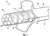
- FIG. 1 is a partial cutaway view of a comparative example of a fiber optic cable 10 not covered by the claims.
- the cable 10 comprises a core 20 surrounded by a jacket 30.
- the jacket 30 has an interior surface 34 that faces the core 20, and an exterior surface 38.
- the jacket 30 can be formed primarily from polymer materials, and can be generally referred to as "polymeric.”
- the terms "polymer” and “polymeric” indicate materials comprised primarily of extrudable polymer materials such as, for example, copolymers, but allows for the presence of non-polymer materials such as additives and fillers.
- the core 20 can be, for example, an assembly or arrangement having data-transmission and/or power-transmission capabilities.
- the core 20 includes a bundle of optical fibers 40 bundled within contrahelically wound binders 44, 46, the optical fibers being capable of conveying optical data.
- the jacket 30 includes a separation feature that facilitates access to the core 20.
- the separation feature is a pair of extruded discontinuities 50 that extend along the length of the cable 10.
- discontinuity indicates a portion of the jacket 30 of different material composition than the main portion of the jacket 30, the main portion being indicated by reference number 55.
- the main portion 55 can essentially be an annular hoop surrounding the core 20, with the discontinuities 50 extending longitudinally through the main portion 55 along a selected length of the cable 10.
- the discontinuities 50 provide lines of weakness that allow the jacket 30 to be separated as shown in FIG. 1 .
- the illustrated discontinuities 50 along the entire cable length, although shorter lengths may be used to provide access to the core 20.
- FIG. 2 is a cross-section of the jacket 30 in isolation, taken on a plane perpendicular to a length of the cable 10.
- the discontinuities 50 are bonded to the main portion of the jacket 55 when the jacket 30 is extruded.
- the main portion 55 and the discontinuities 50 can be formed from extrudable polymers, so that as the extrudates used to form the main portion 55 and the discontinuities 50 cool and solidify, the extrudates become bonded to a desired degree at an interface 54 on each side of a discontinuity 50.
- the bond between discontinuity 50 and the remainder of the jacket 30 can be generally described as enabled by polymer chain entanglement as the jacket 30 solidifies.
- the jacket 30 accordingly comprises a cohesive composite polymer structure.
- the interfaces 54 are shown as clear delineations, while in practice there may be a transition region between the materials of the main portion 55 and the discontinuities 50.
- the curved "T" or “shark tooth” shapes of the discontinuities 50 in FIG. 2 are a result of the extrusion process used to form the discontinuities, but other shapes are possible.
- the discontinuities 50 can be strips that may each occupy up to, for example, 5% of the total jacket cross-sectional area AJ.
- the discontinuities 50 can be relatively narrow strips in the jacket 30, and may occupy relatively small portions of the jacket cross-sectional area AJ.
- the discontinuities 50 can have cross-sectional areas AD that are less than 3% of AJ.
- the discontinuities 50 each have cross-sectional areas AD that are less than 2% of AJ.
- two discontinuities 50 are formed in the jacket 30 to facilitate opening of the jacket as shown in FIG. 1 .
- the number, spacing, shape, composition and other aspects of the discontinuities 50 can be varied.
- a single discontinuity in the jacket 30 may be sufficient to allow the cable jacket 30 to be opened away from the core 20.
- FIG. 3 is an isolated view of one of the discontinuities 50 in the jacket 30.
- the width of the discontinuity 50 is much greater near the exterior surface 38 of the jacket 30 than at the radially inward portion of the discontinuity 50.
- the discontinuities 50 can accordingly form a small, visible portion of the exterior surface of the cable jacket 30. This is due to the manufacturing process used to form the exemplary jacket, in which the extrudate used to form the discontinuity 50 is introduced from the direction 60 into the extrudate material used to form the main portion 55.
- the discontinuities 50 are progressively narrower as they extend radially inwardly.
- the discontinuity extends a depth D into the jacket 30, which has a thickness T.
- a discontinuity 50 may extend from the exterior surface 38 to the depth D, leaving a gap 56 that is contiguous with main portion 55.
- Gap 56 may be from about 0.2 millimeter (mm) to about 0.4 mm, and in examples not according to the invention the gap 56 is about 0.3 mm.
- discontinuity 50 may extend essentially from the exterior surface 38 to the interior surface 34 of the jacket 30.
- the depth D need not equal the thickness T, however. For example, discontinuities having depths D of at least 80% of the thickness T may be effective in providing shear locations for tearing the jacket 30. Discontinuities having depths D of at least 50% of the thickness T may also be effective in providing shear locations for tearing the jacket 30.
- the materials and processes used to form the main portion 55 and the discontinuities 50 can be selected so that the interfaces 54 allow for relatively easy access to the core 20 by tearing the jacket 30 as shown in FIG. 1 .
- the cable 10 may be constructed to meet other requirements for robustness, such as requirements for the jacket 30 stay intact under tensile loads, twisting, in temperature variations, and when subjected to other known cable test criteria, such as, for example, ICEA 460, and GR20.
- the cable jacket main portions 55 and the discontinuities 50 described in this specification may be made from various polymer materials.
- Either the main portion 55 or the discontinuities 50 may be made from polypropylene (PP), polyethylene (PE), or blends of materials such as a blend of PE and ethylene vinyl acetate (EVA), flame-retardant material such as flame-retardant polyethylene, flame-retardant polypropylene, polyvinyl chloride (PVC), or polyvinylidene fluoride (PVDF), filled materials such as polybutylene terephthalate (PBT), a polycarbonate and/or a polyethylene (PE) material and/or an ethylene vinyl acrylate (EVA) or other blends thereof having fillers like a chalk, talc, or the like, and other materials such as a UV-curable acrylates.
- PP polypropylene
- PE polyethylene
- EVA ethylene vinyl acetate
- PVDF polyvinylidene fluoride
- filled materials such
- the main portion can be extruded from a first material comprising at least 80% of a first polymer, polyethylene, by weight, and the discontinuities can be extruded from a second material comprising at least 70% of a second polymer, polypropylene, by weight and additionally at least 0.5% of the first polymer polyethylene by weight.
- higher amounts by weight of the first polymer are included in the second material, such as at least 1.0%, or at least 2%.
- the bond between polypropylene and polyethylene may be caused by one or both of quantities of ethylene that are compounded in the polypropylene bonding with the polyethylene, and molecular entanglement between the PE and PP.
- the amount of ethylene in the PP extrudate can be increased to increase the bond between the discontinuities and the remainder of the jacket.
- the main portion 55 is made from a first polyethylene extruded material, such as a medium density polyethylene (MDPE).
- MDPE medium density polyethylene
- the discontinuities 50 are made from a second, polypropylene/polyethylene blend of extruded material, the blend including from 6% to 20% polyethylene, with the remainder of the blend being primarily a polypropylene material.
- the cable 10 can be manufactured using existing coextrusion equipment subject to minor modifications.
- extruders from the Davis-Standard line of wire and cable extruders can be used to form a cable jacket according to the present embodiments.
- a 1-1/2 inch (40 mm) barrel diameter extruder and a larger barrel diameter extruder, such as a 3, 4, or 4-1/2 inch extruder available from Davis-Standard can be screwed into a crosshead in a configuration that would conventionally be used to extrude a cable jacket with the larger extruder, and to extrude a stripe on the exterior of the cable jacket with the smaller extruder.
- the stripe extrudate material is deposited on the surface of the jacket extrudate.
- the flow of extrudate in the jacket extruder is diverted at the location or locations where the stripe extrudate material is introduced to the jacket extrudate.
- the diversion of the jacket extrudate creates a depression or trough in the flow of jacket extrudate, into which the extrudate material used to form a discontinuity is introduced.
- the jacket extrudate along with the discontinuities formed therein then contracts and solidifies around a fiber optic core advancing through the crosshead.
- FIG. 4 illustrates a cutaway section view of a coextrusion apparatus 100 that can be screwed into a crosshead and used to manufacture a cable according to the present examples.
- the arrows in FIG. 4 illustrate the flow direction of extrudate.
- FIG. 5 illustrates the coextrusion apparatus 100 including representations of the extrudate materials forming the jacket 30.
- the apparatus 100 can generally be constructed from commercially available components used in a cable jacketing line with the capability to extrude stripes on a cable jacket, except for the modification described below.
- the apparatus 100 includes a first input port 110 that receives a first molten extrudate material 112 that is used to form the main portion 55 of the jacket 30.
- a second input port 120 allows introduction of a second molten extrudate material 122 used to form the discontinuities 50.
- a cavity 130 houses a tip (not shown) that in part defines the shape of the extrusion cone 136, and the ultimate form of the cable jacket.
- FIG. 6 illustrates a ring 150 that may be inserted in the apparatus 100 that enables formation of the discontinuities in the flow of the first extrudate material 112.
- the ring 150 includes two projections 152 that act to divert the flow of the first extrudate 112.
- the projections 152 divert the flow of the first extrudate 112 and create a trough or depression in the extrudate flow, into which the second extrudate material 122 flows.
- a cable core (not shown) is advanced along the centerline of the apparatus 100.
- First extrudate material 112 is pumped into the first input port 110, which then advances through channels in the apparatus 100 and travels over the tip (not shown).
- the projections 152 divert the flow of extrudate 112 and create troughs.
- the second extrudate material 122 is introduced into the troughs.
- a space (not shown) between the innermost surfaces of projections 152 and the inner cone of apparatus 100 allows extrudate 112 to flow underneath projections 152, creating a contiguous flow of extrudate 112 beside and beneath the second extrudate material 122.
- the second extrudate material 122 therefore flows as a liquid in the flow of first extrudate material 112 as the jacket is extruded.
- the extrusion cone 136 which is comprised of the first and second extrudate materials 112, 122, cools and solidifies around the core to form the jacket 30.
- FIG. 7 is a partial cutaway view of a fiber optic cable 310 that can be constructed using the processes described herein, with relatively closely spaced discontinuities.
- the cable 310 has a core 320 surrounded by a jacket 330, similar to the embodiment shown in FIG. 1 .
- the jacket 330 includes a pair of discontinuities 350 that extend along the length of the cable 330.
- the discontinuities 350 are relatively close together so that a narrow strip of jacket 330 can be peeled away from the core 320.
- the discontinuities 350 each occupy less than 5% of the total jacket area AJ of the cable 310, and are separated by an angular distance of less than 60 degrees. For a relatively narrow strip providing easy tearing from the remainder of the cable, the angular separation can be less than 30 degrees.
- At least two discontinuities in a cable jacket are arranged to provide relatively easy access to a cable core.
- the ease of access can be defined, for example, by the force required to pull, or peel away a section of the cable jacket at one or more discontinuities.
- the peel force can be measured as a direct force measurement, in Newtons, of the force a person must exert as the jacket section is peeled away from the cable core. It is understood that the jacket will not be perfectly uniform, and that a person or machine cannot exert a perfectly uniform force as the jacket is peeled, so "peel forces" described in this specification indicate an average force exerted as a distance of the jacket section is peeled back.
- peel forces according to the present embodiments are measured without any additional modifications to the cable jacket exterior, such as by scoring.
- the peel forces can be relatively low when compared to the forces required to access a cable without extruded discontinuities.
- a peel force required to peel the narrow strip of jacket 330 shown in FIG. 7 is less than about 80 Newtons (N).
- the peel force required may be from about 10N to about 50N, and in yet further exemplary embodiments may be from about 20N to about 40N.
- Peel forces are defined herein to include any force great enough to cause the jacket material to rip, tear, or otherwise separate along the discontinuities 50, 350 for accessing the cable core.
- Spaced discontinuities such as those shown in FIGS. 2 and 7 , allow access at relatively low peel forces.
- Narrowly spaced discontinuities such as those shown in FIG. 7 provide easy access at very low peel forces.
- the force gauge is pulled by hand or by some mechanical means, away from the cable at an angle of 45 degrees to the cable centerline, until the section of the jacket attached to the S hook peels away from the rest of the jacket.
- the jacket section is pulled for a distance of 250-500 mm away from the initial jacket removal location.
- the average peel can be calculated as the average force measured by the force gauge as the jacket section is pulled along the selected distance.
- a force testing machine such as those available from Instron ® pulls the section of cable away from the remainder of the cable at angle of 90 degrees to the remainder of the cable 10.
- the cable is secured to a linear slide that translates the cable beneath the portion of the machine that is secured to the jacket section being peeled away.
- the cable 10 slides beneath the force gauge that measures the tension on the section being removed, so that the section can be peeled away at a 90 degree angle.
- the tension in the removable section can be averaged over a desired distance to obtain the average peel force.
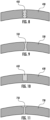
- FIGS. 8-11 are isolated cross-sectional views of comparative examples of discontinuities not according to the invention.
- the main portion 430 has discontinuity 450 disposed therein with a substantially serrated cross-section.
- the main portion 530 has an "hourglass" cross-section.
- Discontinuities 450 and 550 may extend from respective exterior surfaces to respective interior surfaces of respective main portions 430 and 530.
- the main portion 630 has a generally rectangular shape discontinuity 650 that extends from the exterior surface of the main portion 630.
- the discontinuity 650 extends only partially through the main portion 630 and leaves a gap 656, similar to the gap 56 illustrated in FIG. 3 .
- FIG. 11 shows yet another example of a main portion 730 having a discontinuity 750 but having a substantially "I" shaped cross-section.
- the discontinuity 750 extends from the exterior surface of main portion 730 to the interior surface.
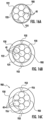
- FIGS. 12-15 are isolated cross-sectional views of embodiments of discontinuities that are wholly encased or embedded in the main portion of the cable jackets, as opposed to extending to the cable exterior.
- FIG. 12 illustrates a main portion 830 with a wholly embedded discontinuity 850 disposed therein having a substantially rectangular cross-section, with a diagonal axis of the rectangle generally aligned with a radius of the cable.
- FIG. 13 illustrates a main portion 860 having a wholly embedded discontinuity 830 disposed therein with a substantially round cross-section.
- FIG. 14 illustrates a main portion 830 having a pair of wholly embedded discontinuities 862 disposed therein, each having a substantially round cross-section. In FIG. 14 , the two discontinuities 862 are arranged on a line that can coincide with a radius of the cable.
- FIG. 15 illustrates a main portion 830 with a wholly embedded discontinuity 870 having a substantially ovoid shaped cross-section.
- FIGS. 16A-16C illustrate an alternative method of forming a cable jacket not according to the invention in which an exterior jacket with one or more discontinuities in extruded over an inner jacket layer.
- a core 900 is advanced along a process direction in a cable jacketing line.
- the core 900 may include, for example, at least one optical fiber 40, a plurality of optical fibers, buffered fibers, ribbon fibers, binders, and/or combinations thereof.
- the core 900 is passed through an extrusion apparatus having an extruder head, where a first, inner jacket layer 920 is extruded around core 900, enclosing the core 900 as shown in FIG. 16A .
- the first jacket layer 900 can be formed from a first polymeric material such as a polyethylene.
- the first jacket layer 900 may be from about 0.1 mm to about 0.6 mm thick, and in exemplary embodiments in the range of 0.3-0.4 mm.
- the first jacket layer 920 has an exterior surface 922 and an interior surface 924, the interior surface 924 being adjacent to and in some cases contacting the core 900.
- the core 900 and the first, inner jacket layer 920 are advanced to a second extrusion apparatus having a second extruder head, where a second jacket layer 930 is extruded over the first jacket layer 920.
- the second jacket layer 930 can abut and, if desired, at least partially bond with the first, inner jacket layer 920.
- the second, outer jacket layer 930 may also be formed from the same material as the first, inner jacket layer 920.
- the second jacket layer 930 may be from about 0.5 mm to about 1.0 mm thick, and may be about 0.7 mm thick.
- the second jacket layer 930 can be formed using an apparatus similar to that shown in FIGS. 4-6 , where one or more troughs are formed by a projection extending into the first extruded material flow path and a second extruded material is introduced into the trough to form a discontinuity 950 in second jacket layer 930.
- the discontinuities 950 may extend radially up to 100% of the thickness of the second layer 930.
- the first layer 920, the second layer 930 and the discontinuities 950 draw down and cool around core 900.
- the two layers 920, 930 blend and form a bond that effectively eliminates, for example, any weld line, stitch line, inconsistency, or incongruence that may cause a likely high stress area between the respective layers 920, 930.
- the first layer 920 and the second layer 930 form a uniform homogeneous layer of first extruded material, with one or more discontinuities formed 950 therein.
- the two layers 920, 930 and the discontinuities 950 thus form a unitary composite structure.
- FIG. 16C illustrates a cable embodiment 980 formed according to this method.
- a gap 956 of the first extrudate material, which corresponds to that portion of the first jacket layer 920, can remain between each discontinuity 950 and the core 900.
- the separation properties disclosed in this specification may be obtained by coextruding the discontinuities from a different material than the material used to form the main portion of the jacket not according to the invention.
- the discontinuities may be made from the same material as the remainder of the jacket, but subjected to different curing conditions, for example.
Landscapes
- Engineering & Computer Science (AREA)
- Mechanical Engineering (AREA)
- Physics & Mathematics (AREA)
- Manufacturing & Machinery (AREA)
- General Physics & Mathematics (AREA)
- Optics & Photonics (AREA)
- Health & Medical Sciences (AREA)
- Ophthalmology & Optometry (AREA)
- Insulated Conductors (AREA)
- Extrusion Moulding Of Plastics Or The Like (AREA)
- Manufacturing Of Electric Cables (AREA)
Description
- A fiber optic cable is disclosed, specifically a fiber optic cable having access features for accessing a core of the fiber optic cable.
- Fiber optic cables frequently require that the fibers inside are accessed midspan rather than at an end of the cable. This often requires the cable jacket to be cut and a portion of the jacket to be removed, allowing access to the fibers inside the jacket. Conventional cutting tools, such as box cutters or custom cutting tools, can be cumbersome and dangerous, both to the operator and to the delicate fibers. Rip cords in a cable jacket can be used for cable access, but they add cost and require time and training in order for the craftsman to use them properly. In one conventional access process, a jacket is pierced using a first tool, and a second tool is used to "fish" out enough of the rip cord so that a third tool (e.g., pliers) can grasp the rip cord. A pull force must then be applied to the rip cord, tearing it through the jacket material. The jacket material is then peeled away from the cable core and removed. If the rip cord breaks, the cord must be "fished" out again.
-
US5970196 A discloses an optical fiber carrier having at least one protective member comprising a buffer tube. The buffer tube has a removable section removal of which permits separation of the buffer tube for access to optical fibers in the tube. The buffer tube includes an optical fiber ribbon with a removable section for facilitating separation of a protective member. - Additional Prior Art is given by
JP09230184 A US2006/0045443 A1 , byWO2005/096053 A1 , and byWO2008/002292 A1 . - Additional Prior Art according to Art. 54 (3) EPC is given by
WO2012/058181 A1 . - The invention provides a cable according to claim 1. The cable comprises a core including a plurality of optical fibers and a jacket surrounding the core. The jacket includes a main portion of a polymeric first extruded material, and at least a first and a second discontinuity of a second extruded material disposed in the main portion, each discontinuity having a bond with the main portion, with a section of the main portion located between the first and second discontinuities being separable from a remainder of the jacket by a peel force exerted on the section. The peel force may be relatively low to allow ease of access to the cable core. The peel force is less than 80 Newtons and may fall in the range of 20-40 Newtons.
- The discontinuities may extend substantially along the entire length of the cable, or along a selected length of the cable to provide access to the core.
- The first polymer may be a polyethylene and the second extruded material may be a polypropylene/polyethylene blend, the blend including from about 6% to about 20% by weight of the polyethylene.
- The cable includes two discontinuities that are angularly spaced in the cable jacket. The discontinuities can be spaced at selected angles to provide varying degrees of required peel force.
- The invention provides a method of making a cable according to claim 9.
- It is to be understood that both the foregoing general description and the following detailed description are merely exemplary, and are intended to provide an overview or framework to understand the nature and character of the claims.
- According to common practice, the various features of the drawings discussed below are not necessarily drawn to scale. Dimensions of various features and elements in the drawings may be expanded or reduced to more clearly illustrate the embodiments of the invention.
-
FIG. 1 is a partial cutaway view of a fiber optic cable not according to the invention; -
FIG. 2 is a cross-section of the cable jacket illustrated inFIG. 1 ; -
FIG. 3 is an isolated cross-sectional view of one of the discontinuities in the cable jacket ofFIG. 2 ; -
FIG. 4 is a cutaway view of a coextrusion apparatus used to manufacture cables with discontinuities; -
FIG. 5 is a cutaway view of the coextrusion apparatus ofFIG. 4 illustrating extrudate material flow; -
FIG. 6 illustrates a ring that can be used to modify conventional coextrusion devices to form discontinuities; -
FIG. 7 is a partial cutaway view of a fiber optic cable not according to the invention; -
FIGS. 8-11 are isolated cross-sectional views of comparatives examples of the discontinuities in a cable jacket not according to the invention; -
FIGS. 12-15 are isolated cross-sectional views of alternate embodiments of the discontinuities in a cable jacket; -
FIGS. 16A-16C illustrate an alternate method of making a cable jacket with discontinuities in two extruded layers not according to the invention. - Reference is now made in detail to examples of which are illustrated in the accompanying drawings. Whenever possible, identical or similar reference numerals are used throughout the drawings to refer to identical or similar parts.
-
FIG. 1 is a partial cutaway view of a comparative example of a fiberoptic cable 10 not covered by the claims. Thecable 10 comprises acore 20 surrounded by ajacket 30. Thejacket 30 has aninterior surface 34 that faces thecore 20, and anexterior surface 38. Thejacket 30 can be formed primarily from polymer materials, and can be generally referred to as "polymeric." In this specification, the terms "polymer" and "polymeric" indicate materials comprised primarily of extrudable polymer materials such as, for example, copolymers, but allows for the presence of non-polymer materials such as additives and fillers. Thecore 20 can be, for example, an assembly or arrangement having data-transmission and/or power-transmission capabilities. In the illustrated embodiment, thecore 20 includes a bundle ofoptical fibers 40 bundled within contrahelicallywound binders - The
jacket 30 includes a separation feature that facilitates access to thecore 20. The separation feature is a pair ofextruded discontinuities 50 that extend along the length of thecable 10. In this specification, the term "discontinuity" indicates a portion of thejacket 30 of different material composition than the main portion of thejacket 30, the main portion being indicated byreference number 55. Themain portion 55 can essentially be an annular hoop surrounding thecore 20, with thediscontinuities 50 extending longitudinally through themain portion 55 along a selected length of thecable 10. According to one aspect, thediscontinuities 50 provide lines of weakness that allow thejacket 30 to be separated as shown inFIG. 1 . The illustrateddiscontinuities 50 along the entire cable length, although shorter lengths may be used to provide access to thecore 20. -
FIG. 2 is a cross-section of thejacket 30 in isolation, taken on a plane perpendicular to a length of thecable 10. Thediscontinuities 50 are bonded to the main portion of thejacket 55 when thejacket 30 is extruded. Themain portion 55 and thediscontinuities 50 can be formed from extrudable polymers, so that as the extrudates used to form themain portion 55 and thediscontinuities 50 cool and solidify, the extrudates become bonded to a desired degree at aninterface 54 on each side of adiscontinuity 50. When thediscontinuities 50 are formed while extruding in the same step as themain portion 55 of the jacket, the bond betweendiscontinuity 50 and the remainder of thejacket 30 can be generally described as enabled by polymer chain entanglement as thejacket 30 solidifies. Thejacket 30 accordingly comprises a cohesive composite polymer structure. InFIG. 2 theinterfaces 54 are shown as clear delineations, while in practice there may be a transition region between the materials of themain portion 55 and thediscontinuities 50. The curved "T" or "shark tooth" shapes of thediscontinuities 50 inFIG. 2 are a result of the extrusion process used to form the discontinuities, but other shapes are possible. - The
discontinuities 50 can be strips that may each occupy up to, for example, 5% of the total jacket cross-sectional area AJ. Thediscontinuities 50 can be relatively narrow strips in thejacket 30, and may occupy relatively small portions of the jacket cross-sectional area AJ. For example, thediscontinuities 50 can have cross-sectional areas AD that are less than 3% of AJ. In the illustrated only comparative example not according to the invention, thediscontinuities 50 each have cross-sectional areas AD that are less than 2% of AJ. InFIGS. 1 and2 , twodiscontinuities 50 are formed in thejacket 30 to facilitate opening of the jacket as shown inFIG. 1 . Depending on the form that thecore 20 takes, the number, spacing, shape, composition and other aspects of thediscontinuities 50 can be varied. For example, a single discontinuity in thejacket 30 may be sufficient to allow thecable jacket 30 to be opened away from thecore 20. -
FIG. 3 is an isolated view of one of thediscontinuities 50 in thejacket 30. The width of thediscontinuity 50 is much greater near theexterior surface 38 of thejacket 30 than at the radially inward portion of thediscontinuity 50. Thediscontinuities 50 can accordingly form a small, visible portion of the exterior surface of thecable jacket 30. This is due to the manufacturing process used to form the exemplary jacket, in which the extrudate used to form thediscontinuity 50 is introduced from thedirection 60 into the extrudate material used to form themain portion 55. Thediscontinuities 50 are progressively narrower as they extend radially inwardly. The discontinuity extends a depth D into thejacket 30, which has a thickness T. In comparative examples not according to the invention, adiscontinuity 50 may extend from theexterior surface 38 to the depth D, leaving agap 56 that is contiguous withmain portion 55.Gap 56 may be from about 0.2 millimeter (mm) to about 0.4 mm, and in examples not according to the invention thegap 56 is about 0.3 mm. In other comparative examples not according to the invention,discontinuity 50 may extend essentially from theexterior surface 38 to theinterior surface 34 of thejacket 30. The depth D need not equal the thickness T, however. For example, discontinuities having depths D of at least 80% of the thickness T may be effective in providing shear locations for tearing thejacket 30. Discontinuities having depths D of at least 50% of the thickness T may also be effective in providing shear locations for tearing thejacket 30. - The materials and processes used to form the
main portion 55 and thediscontinuities 50 can be selected so that theinterfaces 54 allow for relatively easy access to the core 20 by tearing thejacket 30 as shown inFIG. 1 . Thecable 10 may be constructed to meet other requirements for robustness, such as requirements for thejacket 30 stay intact under tensile loads, twisting, in temperature variations, and when subjected to other known cable test criteria, such as, for example, ICEA 460, and GR20. - The cable jacket
main portions 55 and thediscontinuities 50 described in this specification may be made from various polymer materials. Either themain portion 55 or thediscontinuities 50 may be made from polypropylene (PP), polyethylene (PE), or blends of materials such as a blend of PE and ethylene vinyl acetate (EVA), flame-retardant material such as flame-retardant polyethylene, flame-retardant polypropylene, polyvinyl chloride (PVC), or polyvinylidene fluoride (PVDF), filled materials such as polybutylene terephthalate (PBT), a polycarbonate and/or a polyethylene (PE) material and/or an ethylene vinyl acrylate (EVA) or other blends thereof having fillers like a chalk, talc, or the like, and other materials such as a UV-curable acrylates. - In the examples not according to the invention, the main portion can be extruded from a first material comprising at least 80% of a first polymer, polyethylene, by weight, and the discontinuities can be extruded from a second material comprising at least 70% of a second polymer, polypropylene, by weight and additionally at least 0.5% of the first polymer polyethylene by weight. According to the invention, higher amounts by weight of the first polymer are included in the second material, such as at least 1.0%, or at least 2%. Without being bound by theory, Applicants believe the bond between polypropylene and polyethylene may be caused by one or both of quantities of ethylene that are compounded in the polypropylene bonding with the polyethylene, and molecular entanglement between the PE and PP. According to this understanding, the amount of ethylene in the PP extrudate can be increased to increase the bond between the discontinuities and the remainder of the jacket. In one embodiment, the
main portion 55 is made from a first polyethylene extruded material, such as a medium density polyethylene (MDPE). Thediscontinuities 50 are made from a second, polypropylene/polyethylene blend of extruded material, the blend including from 6% to 20% polyethylene, with the remainder of the blend being primarily a polypropylene material. - The
cable 10 can be manufactured using existing coextrusion equipment subject to minor modifications. For example, extruders from the Davis-Standard line of wire and cable extruders can be used to form a cable jacket according to the present embodiments. For example, a 1-1/2 inch (40 mm) barrel diameter extruder and a larger barrel diameter extruder, such as a 3, 4, or 4-1/2 inch extruder available from Davis-Standard, can be screwed into a crosshead in a configuration that would conventionally be used to extrude a cable jacket with the larger extruder, and to extrude a stripe on the exterior of the cable jacket with the smaller extruder. In a conventional process, the stripe extrudate material is deposited on the surface of the jacket extrudate. According to the present embodiment, the flow of extrudate in the jacket extruder is diverted at the location or locations where the stripe extrudate material is introduced to the jacket extrudate. The diversion of the jacket extrudate creates a depression or trough in the flow of jacket extrudate, into which the extrudate material used to form a discontinuity is introduced. The jacket extrudate along with the discontinuities formed therein then contracts and solidifies around a fiber optic core advancing through the crosshead. -
FIG. 4 illustrates a cutaway section view of acoextrusion apparatus 100 that can be screwed into a crosshead and used to manufacture a cable according to the present examples. The arrows inFIG. 4 illustrate the flow direction of extrudate.FIG. 5 illustrates thecoextrusion apparatus 100 including representations of the extrudate materials forming thejacket 30. Theapparatus 100 can generally be constructed from commercially available components used in a cable jacketing line with the capability to extrude stripes on a cable jacket, except for the modification described below. Referring toFIGS. 4 and 5 , theapparatus 100 includes afirst input port 110 that receives a firstmolten extrudate material 112 that is used to form themain portion 55 of thejacket 30. Asecond input port 120 allows introduction of a secondmolten extrudate material 122 used to form thediscontinuities 50. Acavity 130 houses a tip (not shown) that in part defines the shape of theextrusion cone 136, and the ultimate form of the cable jacket. -
FIG. 6 illustrates aring 150 that may be inserted in theapparatus 100 that enables formation of the discontinuities in the flow of thefirst extrudate material 112. Thering 150 includes twoprojections 152 that act to divert the flow of thefirst extrudate 112. Theprojections 152 divert the flow of thefirst extrudate 112 and create a trough or depression in the extrudate flow, into which thesecond extrudate material 122 flows. - Referring to
FIG. 5 , to form afiber optic cable 10, a cable core (not shown) is advanced along the centerline of theapparatus 100.First extrudate material 112 is pumped into thefirst input port 110, which then advances through channels in theapparatus 100 and travels over the tip (not shown). Theprojections 152 divert the flow ofextrudate 112 and create troughs. At these locations, thesecond extrudate material 122 is introduced into the troughs. In exemplary embodiments, a space (not shown) between the innermost surfaces ofprojections 152 and the inner cone ofapparatus 100 allowsextrudate 112 to flow underneathprojections 152, creating a contiguous flow ofextrudate 112 beside and beneath thesecond extrudate material 122. Thesecond extrudate material 122 therefore flows as a liquid in the flow offirst extrudate material 112 as the jacket is extruded. Theextrusion cone 136, which is comprised of the first andsecond extrudate materials jacket 30. -
FIG. 7 is a partial cutaway view of afiber optic cable 310 that can be constructed using the processes described herein, with relatively closely spaced discontinuities. Thecable 310 has a core 320 surrounded by ajacket 330, similar to the embodiment shown inFIG. 1 . Thejacket 330 includes a pair ofdiscontinuities 350 that extend along the length of thecable 330. In this example, thediscontinuities 350 are relatively close together so that a narrow strip ofjacket 330 can be peeled away from the core 320. Thediscontinuities 350 each occupy less than 5% of the total jacket area AJ of thecable 310, and are separated by an angular distance of less than 60 degrees. For a relatively narrow strip providing easy tearing from the remainder of the cable, the angular separation can be less than 30 degrees. - According to the present embodiments, at least two discontinuities in a cable jacket are arranged to provide relatively easy access to a cable core. The ease of access can be defined, for example, by the force required to pull, or peel away a section of the cable jacket at one or more discontinuities. The peel force can be measured as a direct force measurement, in Newtons, of the force a person must exert as the jacket section is peeled away from the cable core. It is understood that the jacket will not be perfectly uniform, and that a person or machine cannot exert a perfectly uniform force as the jacket is peeled, so "peel forces" described in this specification indicate an average force exerted as a distance of the jacket section is peeled back. It is also understood that peel forces according to the present embodiments are measured without any additional modifications to the cable jacket exterior, such as by scoring. The peel forces can be relatively low when compared to the forces required to access a cable without extruded discontinuities. For example, a peel force required to peel the narrow strip of
jacket 330 shown inFIG. 7 is less than about 80 Newtons (N). In exemplary embodiments, the peel force required may be from about 10N to about 50N, and in yet further exemplary embodiments may be from about 20N to about 40N. Peel forces are defined herein to include any force great enough to cause the jacket material to rip, tear, or otherwise separate along thediscontinuities FIGS. 2 and7 , allow access at relatively low peel forces. Narrowly spaced discontinuities such as those shown inFIG. 7 provide easy access at very low peel forces. - It is relatively easy to measure peel force. Using cable 10 (
FIG. 1 ) as a reference, about 25 mm of jacket is cut away from one end of thecable 10. The ends of thecable 10 are secured to a bench or other sturdy surface. A small hole is placed in the jacket proximal to the edge of the jacket where it was cut away from the core, and one end of an "S" hook is inserted into the hole in the jacket. If the cable includes a pair of spaced discontinuities, the hole is formed midway between the two discontinuities. A lanyard or wire is attached to the other end of the S hook. The lanyard is fixed to a force gauge, such as a Chatillon gauge available from Ametek Test and Calibration Instruments of Largo, Florida. The force gauge is pulled by hand or by some mechanical means, away from the cable at an angle of 45 degrees to the cable centerline, until the section of the jacket attached to the S hook peels away from the rest of the jacket. The jacket section is pulled for a distance of 250-500 mm away from the initial jacket removal location. The average peel can be calculated as the average force measured by the force gauge as the jacket section is pulled along the selected distance. - In an alternate method of measuring peel force, a force testing machine, such as those available from Instron®, pulls the section of cable away from the remainder of the cable at angle of 90 degrees to the remainder of the
cable 10. The cable is secured to a linear slide that translates the cable beneath the portion of the machine that is secured to the jacket section being peeled away. In this arrangement, thecable 10 slides beneath the force gauge that measures the tension on the section being removed, so that the section can be peeled away at a 90 degree angle. The tension in the removable section can be averaged over a desired distance to obtain the average peel force. -
FIGS. 8-11 are isolated cross-sectional views of comparative examples of discontinuities not according to the invention. InFIG. 8 , themain portion 430 hasdiscontinuity 450 disposed therein with a substantially serrated cross-section. InFIG. 9 , themain portion 530 has an "hourglass" cross-section.Discontinuities main portions FIG. 10 , themain portion 630 has a generallyrectangular shape discontinuity 650 that extends from the exterior surface of themain portion 630. Thediscontinuity 650 extends only partially through themain portion 630 and leaves a gap 656, similar to thegap 56 illustrated inFIG. 3 .FIG. 11 shows yet another example of amain portion 730 having adiscontinuity 750 but having a substantially "I" shaped cross-section. Thediscontinuity 750 extends from the exterior surface ofmain portion 730 to the interior surface. -
FIGS. 12-15 are isolated cross-sectional views of embodiments of discontinuities that are wholly encased or embedded in the main portion of the cable jackets, as opposed to extending to the cable exterior.FIG. 12 illustrates amain portion 830 with a wholly embeddeddiscontinuity 850 disposed therein having a substantially rectangular cross-section, with a diagonal axis of the rectangle generally aligned with a radius of the cable.FIG. 13 illustrates amain portion 860 having a wholly embeddeddiscontinuity 830 disposed therein with a substantially round cross-section.FIG. 14 illustrates amain portion 830 having a pair of wholly embeddeddiscontinuities 862 disposed therein, each having a substantially round cross-section. InFIG. 14 , the twodiscontinuities 862 are arranged on a line that can coincide with a radius of the cable.FIG. 15 illustrates amain portion 830 with a wholly embeddeddiscontinuity 870 having a substantially ovoid shaped cross-section. -
FIGS. 16A-16C illustrate an alternative method of forming a cable jacket not according to the invention in which an exterior jacket with one or more discontinuities in extruded over an inner jacket layer. Referring toFIG. 16A , acore 900 is advanced along a process direction in a cable jacketing line. Thecore 900 may include, for example, at least oneoptical fiber 40, a plurality of optical fibers, buffered fibers, ribbon fibers, binders, and/or combinations thereof. Thecore 900 is passed through an extrusion apparatus having an extruder head, where a first,inner jacket layer 920 is extruded aroundcore 900, enclosing thecore 900 as shown inFIG. 16A . Thefirst jacket layer 900 can be formed from a first polymeric material such as a polyethylene. Thefirst jacket layer 900 may be from about 0.1 mm to about 0.6 mm thick, and in exemplary embodiments in the range of 0.3-0.4 mm. Thefirst jacket layer 920 has anexterior surface 922 and aninterior surface 924, theinterior surface 924 being adjacent to and in some cases contacting thecore 900. - Referring to
FIG. 16B , thecore 900 and the first,inner jacket layer 920 are advanced to a second extrusion apparatus having a second extruder head, where asecond jacket layer 930 is extruded over thefirst jacket layer 920. Thesecond jacket layer 930 can abut and, if desired, at least partially bond with the first,inner jacket layer 920. - In exemplary embodiments, the second,
outer jacket layer 930 may also be formed from the same material as the first,inner jacket layer 920. Thesecond jacket layer 930 may be from about 0.5 mm to about 1.0 mm thick, and may be about 0.7 mm thick. Thesecond jacket layer 930 can be formed using an apparatus similar to that shown inFIGS. 4-6 , where one or more troughs are formed by a projection extending into the first extruded material flow path and a second extruded material is introduced into the trough to form adiscontinuity 950 insecond jacket layer 930. Thediscontinuities 950 may extend radially up to 100% of the thickness of thesecond layer 930. Thefirst layer 920, thesecond layer 930 and thediscontinuities 950 draw down and cool aroundcore 900. - Referring to
FIG. 16C , if thefirst jacket layer 920 and thesecond jacket layer 930 are made from substantially the same extrudate material, the twolayers respective layers first layer 920 and thesecond layer 930 form a uniform homogeneous layer of first extruded material, with one or more discontinuities formed 950 therein. The twolayers discontinuities 950 thus form a unitary composite structure.FIG. 16C illustrates acable embodiment 980 formed according to this method. Agap 956 of the first extrudate material, which corresponds to that portion of thefirst jacket layer 920, can remain between eachdiscontinuity 950 and thecore 900. - In general, the separation properties disclosed in this specification may be obtained by coextruding the discontinuities from a different material than the material used to form the main portion of the jacket not according to the invention. As an alternative method not according to the invention, the discontinuities may be made from the same material as the remainder of the jacket, but subjected to different curing conditions, for example.
Claims (11)
- A cable (10), comprising:a core (20) including a plurality of optical fibers (40); anda jacket (30) surrounding the core (20), the jacket (30) comprising:a main portion (830) of a first material, wherein the first material is extrudable, and wherein the first material is polymeric; andat least a first and a second discontinuity (850, 860, 862, 870) of a second material disposed in the main portion (830), wherein the second material is extrudable, each discontinuity (850, 860, 862, 870) having a bond with the main portion (830), a section of the main portion (830) located between the first and second discontinuities (850, 860, 862, 870) being separable from a remainder of the jacket (30) by a peel force exerted on the section,wherein the first and second discontinuities (850, 860, 862, 870) are wholly embedded in the main portion (830),wherein the second material being polymeric, wherein the first material includes a first polymer and the second material includes a second polymer, andthe jacket (30) having an interior surface (34) facing the cable core and an exterior surface (38)the optical cable being characterised in that the jacket thickness between the interior surface and the exterior surface is from 0.5 mm to 2.0 mm, in that the peel force is less than 80 Newtons, and in that the the second material further includes between 1% and 20% by weight of the first polymer.
- The cable (10) of claim 1, wherein the peel force is less than 50 N.
- The cable (10) of claim 2, wherein the peel force is at least 10 N.
- The cable (10) of claim 1, wherein the peel force is between 20 N and 40 N.
- The cable (10) of claim 1, the first and second discontinuities (850, 860, 862, 870) extending substantially along the entire length of the cable (10).
- The cable (10) of any one of claims 1 to 5, wherein the first material is a polyethylene and the second material is a polypropylene/polyethylene blend, wherein the blend includes from 6% to 20% by weight of the polyethylene.
- The cable (10) of any one of claims 1 to 6, wherein the jacket (30) has an annular cross-section.
- The cable of any one of claims 1 to 7, wherein a cross-sectional area of each discontinuity (850, 860, 862, 870) is less than 5% of a cross-sectional area of the jacket (30).
- A method of making a cable (10), comprising:advancing a core (20) in a first direction, the core (20) comprising fibres being capable of conveying communication signals; andextruding a jacket (30) around the core, the extruding comprising:introducing a first polymeric extrudate material into an extrusion apparatus (100);introducing a first flow of a second polymeric extrudate material into the first polymeric extrudate material to form a first discontinuity (850, 860, 862, 870) in the first polymeric extrudate material;introducing a second flow of the second polymeric extrudate material into the first polymeric extrudate material to form a second discontinuity (850, 860, 862, 870) in the first polymeric extrudate material; andallowing the first and second polymeric extrudate materials to draw down and cool around the core (20), the first and second polymeric extrudate materials forming the jacket (30) around the core (20),the first polymeric extrudated material forming a main portion (830) of the jacket (30),wherein a section of the jacket (30) located between the first and second discontinuities (850, 860, 862, 870) is separable from a remainder of the jacket (30) by a peel force on the section,wherein the first and second discontinuities (850, 860, 862, 870) are wholly embedded in the main portion (830),wherein the first polymeric extrudate material includes a first polymer and the second polymeric extrudate material includes a second polymer,the jacket (30) having an interior surface (34) facing the core andan exterior surface (38), the method being characterised in that the jacket thickness between the interior and the exterior surface is from 0.5 mm to 2.0 mm, in that the peel force is less than 80 Newtons, and in that the second polymeric extrudate material further includes between 1% and 20% by weight of the first polymer.
- The method of claim 9, wherein the first polymeric extrudate material is a polyethylene and the second material is a polypropylene/polyethylene blend, wherein the blend includes from 6% to 20% by weight of the polyethylene.
- The method of any one of claims 9 to 10, wherein a cross-sectional area of each discontinuity (850, 860, 862, 870) is less than 5% of a cross-sectional area of the jacket (30).
Priority Applications (1)
| Application Number | Priority Date | Filing Date | Title |
|---|---|---|---|
| EP23173745.3A EP4235704A3 (en) | 2010-11-23 | 2011-11-23 | Fiber optic cables with access features and method of manufacturing |
Applications Claiming Priority (2)
| Application Number | Priority Date | Filing Date | Title |
|---|---|---|---|
| US41668410P | 2010-11-23 | 2010-11-23 | |
| PCT/US2011/062002 WO2012071490A2 (en) | 2010-11-23 | 2011-11-23 | Fiber optic cables with access features |
Related Child Applications (2)
| Application Number | Title | Priority Date | Filing Date |
|---|---|---|---|
| EP23173745.3A Division EP4235704A3 (en) | 2010-11-23 | 2011-11-23 | Fiber optic cables with access features and method of manufacturing |
| EP23173745.3A Division-Into EP4235704A3 (en) | 2010-11-23 | 2011-11-23 | Fiber optic cables with access features and method of manufacturing |
Publications (2)
| Publication Number | Publication Date |
|---|---|
| EP2643139A2 EP2643139A2 (en) | 2013-10-02 |
| EP2643139B1 true EP2643139B1 (en) | 2023-06-28 |
Family
ID=45218905
Family Applications (2)
| Application Number | Title | Priority Date | Filing Date |
|---|---|---|---|
| EP23173745.3A Withdrawn EP4235704A3 (en) | 2010-11-23 | 2011-11-23 | Fiber optic cables with access features and method of manufacturing |
| EP11793946.2A Active EP2643139B1 (en) | 2010-11-23 | 2011-11-23 | Fiber optic cables with access features and method of manufacturing |
Family Applications Before (1)
| Application Number | Title | Priority Date | Filing Date |
|---|---|---|---|
| EP23173745.3A Withdrawn EP4235704A3 (en) | 2010-11-23 | 2011-11-23 | Fiber optic cables with access features and method of manufacturing |
Country Status (9)
| Country | Link |
|---|---|
| US (3) | US8582939B2 (en) |
| EP (2) | EP4235704A3 (en) |
| CN (2) | CN103260846B (en) |
| AU (1) | AU2011332930B2 (en) |
| CA (1) | CA2817836C (en) |
| ES (1) | ES2955526T3 (en) |
| PL (1) | PL2643139T3 (en) |
| RU (1) | RU143173U1 (en) |
| WO (1) | WO2012071490A2 (en) |
Families Citing this family (56)
| Publication number | Priority date | Publication date | Assignee | Title |
|---|---|---|---|---|
| US20100278492A1 (en) * | 2009-04-30 | 2010-11-04 | Bohler Gregory B | Armored Fiber Optic Assemblies and Methods of Forming Fiber Optic Assemblies |
| EP3929644A1 (en) | 2010-03-02 | 2021-12-29 | Commscope Technologies LLC | Fiber optic cable assembly |
| JP6017415B2 (en) | 2010-04-30 | 2016-11-02 | コーニング オプティカル コミュニケイションズ リミテッド ライアビリティ カンパニー | Optical fiber cable with access feature and method of manufacturing the same |
| EP2633355B1 (en) | 2010-10-28 | 2020-07-15 | Corning Optical Communications LLC | Fiber optic cables with extruded access features and methods of making fiber optic cables |
| AU2011332930B2 (en) | 2010-11-23 | 2017-02-16 | Corning Optical Communications LLC | Fiber optic cables with access features |
| US9274302B2 (en) | 2011-10-13 | 2016-03-01 | Corning Cable Systems Llc | Fiber optic cables with extruded access features for access to a cable cavity |
| US9323022B2 (en) | 2012-10-08 | 2016-04-26 | Corning Cable Systems Llc | Methods of making and accessing cables having access features |
| US8682124B2 (en) | 2011-10-13 | 2014-03-25 | Corning Cable Systems Llc | Access features of armored flat fiber optic cable |
| AU2012322864A1 (en) * | 2011-10-13 | 2014-04-17 | Corning Optical Communications LLC | Methods of making and accessing cables having access features |
| US9201208B2 (en) | 2011-10-27 | 2015-12-01 | Corning Cable Systems Llc | Cable having core, jacket and polymeric jacket access features located in the jacket |
| US9176293B2 (en) | 2011-10-28 | 2015-11-03 | Corning Cable Systems Llc | Buffered fibers with access features |
| US8620123B2 (en) | 2012-02-13 | 2013-12-31 | Corning Cable Systems Llc | Visual tracer system for fiber optic cable |
| US8909014B2 (en) | 2012-04-27 | 2014-12-09 | Corning Cable Systems Llc | Fiber optic cable with access features and jacket-to-core coupling, and methods of making the same |
| US9091830B2 (en) | 2012-09-26 | 2015-07-28 | Corning Cable Systems Llc | Binder film for a fiber optic cable |
| US8620124B1 (en) | 2012-09-26 | 2013-12-31 | Corning Cable Systems Llc | Binder film for a fiber optic cable |
| US11287589B2 (en) | 2012-09-26 | 2022-03-29 | Corning Optical Communications LLC | Binder film for a fiber optic cable |
| US10139579B2 (en) | 2013-07-29 | 2018-11-27 | Prysmian S.P.A. | Optical cable for terrestrial networks |
| US9482839B2 (en) | 2013-08-09 | 2016-11-01 | Corning Cable Systems Llc | Optical fiber cable with anti-split feature |
| US8805144B1 (en) | 2013-09-24 | 2014-08-12 | Corning Optical Communications LLC | Stretchable fiber optic cable |
| US9075212B2 (en) | 2013-09-24 | 2015-07-07 | Corning Optical Communications LLC | Stretchable fiber optic cable |
| US8913862B1 (en) | 2013-09-27 | 2014-12-16 | Corning Optical Communications LLC | Optical communication cable |
| CN103489547B (en) * | 2013-10-08 | 2015-09-09 | 江苏祥源电气设备有限公司 | A kind of composite insulator arbitrarily adjust extrude length extrude technique |
| US9594226B2 (en) | 2013-10-18 | 2017-03-14 | Corning Optical Communications LLC | Optical fiber cable with reinforcement |
| GB2527580B (en) | 2014-06-26 | 2021-07-21 | British Telecomm | Installation of cable connections |
| US9482835B2 (en) * | 2014-06-27 | 2016-11-01 | Corning Optical Communications LLC | Extreme environment optical fiber cable with crack-resistant layer |
| US10379309B2 (en) | 2014-11-18 | 2019-08-13 | Corning Optical Communications LLC | Traceable optical fiber cable and filtered viewing device for enhanced traceability |
| CN105717592A (en) * | 2014-12-05 | 2016-06-29 | 泰科电子(上海)有限公司 | Method for manufacturing optical cable |
| US10228526B2 (en) | 2015-03-31 | 2019-03-12 | Corning Optical Communications LLC | Traceable cable with side-emitting optical fiber and method of forming the same |
| US10101553B2 (en) | 2015-05-20 | 2018-10-16 | Corning Optical Communications LLC | Traceable cable with side-emitting optical fiber and method of forming the same |
| WO2017015085A1 (en) | 2015-07-17 | 2017-01-26 | Corning Optical Communications LLC | Systems and methods for tracing cables and cables for such systems and methods |
| EP3325876A1 (en) | 2015-07-17 | 2018-05-30 | Corning Optical Communications LLC | Systems and methods for traceable cables |
| PL3702821T3 (en) | 2015-08-18 | 2023-09-11 | Corning Optical Communications LLC | Optical fiber bundle |
| EP3357071B1 (en) | 2015-09-28 | 2025-06-25 | Dow Global Technologies LLC | Peelable cable jacket having designed microstructures and methods for making peelable cable jackets having designed microstructures |
| US10720265B2 (en) | 2015-09-28 | 2020-07-21 | Dow Global Technologies Llc | Peelable cable jackets having designed microstructures and methods for making peelable cable jackets having designed microstructures |
| US10101545B2 (en) | 2015-10-30 | 2018-10-16 | Corning Optical Communications LLC | Traceable cable assembly and connector |
| JP6542648B2 (en) * | 2015-11-20 | 2019-07-10 | 住友電気工業株式会社 | Fiber optic cable |
| US10545298B2 (en) | 2016-12-21 | 2020-01-28 | Corning Research & Development Corporation | Traceable fiber optic cable assembly with illumination structure and tracing optical fibers for carrying light received from a light launch device |
| US10185111B2 (en) | 2016-04-08 | 2019-01-22 | Corning Optical Communications LLC | Traceable end point cable assembly |
| US10107983B2 (en) | 2016-04-29 | 2018-10-23 | Corning Optical Communications LLC | Preferential mode coupling for enhanced traceable patch cord performance |
| JP6553299B2 (en) * | 2016-06-08 | 2019-07-31 | ニューブレクス株式会社 | Cable for measuring material pressure, temperature and strain distribution |
| US10067310B2 (en) | 2016-11-03 | 2018-09-04 | Corning Optical Communications LLC | Fiber optic drop cable assembly |
| JP6738434B2 (en) * | 2016-11-17 | 2020-08-12 | 株式会社フジクラ | Optical fiber cable and method of manufacturing optical fiber cable |
| JP7058268B2 (en) | 2016-11-29 | 2022-04-21 | ダウ グローバル テクノロジーズ エルエルシー | Microcapillary wire coating die assembly |
| US10498208B1 (en) | 2016-12-20 | 2019-12-03 | Aerodyne Research, Inc. | Lightweight return flux alternator |
| US10234614B2 (en) | 2017-01-20 | 2019-03-19 | Corning Research & Development Corporation | Light source assemblies and systems and methods with mode homogenization |
| WO2018141681A1 (en) | 2017-02-01 | 2018-08-09 | British Telecommunications Public Limited Company | Optical fibre event location |
| US10983295B2 (en) | 2017-07-11 | 2021-04-20 | Prysmian S.P.A. | Optical cable for terrestrial networks |
| WO2019016263A1 (en) | 2017-07-20 | 2019-01-24 | British Telecommunications Public Limited Company | Optical fibre |
| US10539758B2 (en) | 2017-12-05 | 2020-01-21 | Corning Research & Development Corporation | Traceable fiber optic cable assembly with indication of polarity |
| US10539747B2 (en) | 2017-12-05 | 2020-01-21 | Corning Research & Development Corporation | Bend induced light scattering fiber and cable assemblies and method of making |
| IT201800000476A1 (en) * | 2018-01-03 | 2019-07-03 | Lacoplast It Srl | Unit, implant and method of coextruction |
| AU2019331384A1 (en) * | 2018-08-30 | 2021-03-11 | Omega Flex, Inc. | Tubing system with venting jacket |
| CN109188632A (en) * | 2018-10-17 | 2019-01-11 | 南京华信藤仓光通信有限公司 | A kind of new and effective stripping Loose tube and its extruded mould |
| CN109676890A (en) * | 2019-02-28 | 2019-04-26 | 华迅工业(苏州)有限公司 | A kind of rail traffic cable double-layer coextrusion outer mold |
| US11215777B2 (en) | 2019-07-31 | 2022-01-04 | Corning Research & Development Corporation | Cable skin layer with access sections integrated into a cable jacket |
| CN110993176B (en) * | 2019-11-14 | 2021-01-05 | 安徽尚纬电缆有限公司 | Reel cable for shore power supply |
Citations (6)
| Publication number | Priority date | Publication date | Assignee | Title |
|---|---|---|---|---|
| WO2005096053A1 (en) * | 2004-03-31 | 2005-10-13 | Ccs Technology, Inc. | Mechanically separable cable |
| US20060045443A1 (en) * | 2004-08-30 | 2006-03-02 | Blazer Bradley J | Fiber optic ribbons having one or more preferential tear portions and method of making the same |
| JP2006171570A (en) * | 2004-12-17 | 2006-06-29 | Sumitomo Electric Ind Ltd | Fiber optic cable |
| WO2008002292A1 (en) * | 2006-06-26 | 2008-01-03 | Prysmian Power Cables And Systems Usa, Llc | Electrical power cable with frangible insulation shield |
| WO2011137236A1 (en) * | 2010-04-30 | 2011-11-03 | Corning Cable Systems Llc | Fiber optic cables with access features and methods of making fiber optic cables |
| WO2012058181A1 (en) * | 2010-10-28 | 2012-05-03 | Corning Cable Systems Llc | Fiber optic cables with extruded access features and methods of making fiber optic cables |
Family Cites Families (109)
| Publication number | Priority date | Publication date | Assignee | Title |
|---|---|---|---|---|
| US3076235A (en) | 1960-03-09 | 1963-02-05 | Superior Cable Corp | Method for striping conductor coatings |
| US3991014A (en) | 1974-05-10 | 1976-11-09 | E. I. Du Pont De Nemours And Company | Polyesters of derivatives of hydroquinone and bis(carboxyphenyl)ether |
| US4067852A (en) | 1976-05-13 | 1978-01-10 | Celanese Corporation | Melt processable thermotropic wholly aromatic polyester containing polybenzoyl units |
| US4083829A (en) | 1976-05-13 | 1978-04-11 | Celanese Corporation | Melt processable thermotropic wholly aromatic polyester |
| SE7706752L (en) | 1977-06-09 | 1978-12-10 | Ericsson Telefon Ab L M | CABLE WITH CUTTING WIRE |
| US4130545A (en) | 1977-09-12 | 1978-12-19 | Celanese Corporation | Melt processable thermotropic wholly aromatic polyester comprising both para-oxybenzoyl and meta-oxybenzoyl moieties |
| US4248824A (en) * | 1979-01-24 | 1981-02-03 | Alcan Aluminum Corporation | Method and apparatus for striping extruded polymer products |
| EP0020036B1 (en) | 1979-05-22 | 1982-08-11 | The Post Office | Improved communications cable |
| US4318842A (en) | 1980-10-06 | 1982-03-09 | Celanese Corporation | Polyester of 6-hydroxy-2-naphthoic acid, aromatic diol, and 1,4-cyclohexanedicarboxylic acid capable of undergoing melt processing |
| US4468364A (en) | 1983-04-28 | 1984-08-28 | Celanese Corporation | Process for extruding thermotropic liquid crystalline polymers |
| JPS6091306A (en) | 1983-10-25 | 1985-05-22 | Hitachi Cable Ltd | Reinforcing method of connection part terminal of multicore optical fiber |
| DE3564493D1 (en) | 1984-06-19 | 1988-09-22 | Telephone Cables Ltd | Optical fibre cables |
| DE3624124A1 (en) | 1986-07-17 | 1988-01-21 | Kabelmetal Electro Gmbh | MESSAGE CABLES WITH FOCUS |
| US4729628A (en) | 1986-11-14 | 1988-03-08 | Siecor Corporation | Fiber optic dropwire |
| JPS63120206U (en) | 1987-01-29 | 1988-08-03 | ||
| FR2613981B1 (en) * | 1987-04-15 | 1989-10-13 | Swisscab E A Schoen Sa | METHOD AND HEAD FOR EXTRUDING PROFILES IN SYNTHETIC MATERIAL HAVING COLORED STRIPS |
| DE3922475A1 (en) | 1989-07-06 | 1991-01-17 | Siemens Ag | OPTICAL NEWS CABLE |
| DE4142047C2 (en) | 1991-12-19 | 2001-03-01 | Siemens Ag | Method for covering at least one optical waveguide with a protective layer and for attaching reinforcing elements |
| IT1271484B (en) | 1993-10-12 | 1997-05-28 | Alcatel Cavi Spa | MODULAR OPTICAL FIBER TAPE, SEPARABLE INTO A PLURALITY OF TAPES OR MODULES, PROCEDURE FOR MANUFACTURING SUCH TAPE AND OPTICAL CABLE USING THE SAME |
| DE4406690A1 (en) * | 1994-03-01 | 1995-09-07 | Siemens Ag | Co-extruding optical fibre with core, sheath and tensile reinforcement |
| US5542020A (en) * | 1994-06-10 | 1996-07-30 | Commscope, Inc. | Fiber optic cable having extended contraction window and associated method and apparatus for fabricating the cable |
| US5469523A (en) | 1994-06-10 | 1995-11-21 | Commscope, Inc. | Composite fiber optic and electrical cable and associated fabrication method |
| DE4421456A1 (en) | 1994-06-18 | 1995-12-21 | Kwo Kabel Gmbh | Accurate embedded of optical fibres and tensile elements in a thermoplastic |
| US5442722A (en) | 1994-07-25 | 1995-08-15 | Siecor Corporation | Optical fiber ribbon with zip cord |
| FR2728977B1 (en) | 1995-01-02 | 1997-01-31 | Alcatel Cable | QUICK AND EASY STRIPPING OPTICAL FIBER CABLE |
| FR2735604B1 (en) | 1995-06-14 | 1997-07-18 | Schneider Electric Sa | FLAT CABLE AND STRIPPING PLIERS |
| DE19605276A1 (en) | 1996-02-13 | 1997-08-14 | Siemens Ag | Method and device for manufacturing an optical cable |
| JPH09230184A (en) * | 1996-02-22 | 1997-09-05 | Mitsubishi Cable Ind Ltd | Optical fiber tape |
| JP3172084B2 (en) | 1996-03-12 | 2001-06-04 | 日本電信電話株式会社 | Optical flat cable |
| US5949940A (en) | 1997-05-27 | 1999-09-07 | Corning Incorporated | Enhanced ribbon strippability using coating additives |
| US5717805A (en) | 1996-06-12 | 1998-02-10 | Alcatel Na Cable Systems, Inc. | Stress concentrations in an optical fiber ribbon to facilitate separation of ribbon matrix material |
| US6167180A (en) | 1997-09-12 | 2000-12-26 | Alcatel | Cable having at least one layer of flexible strength members with adhesive and non-adhesive yarns for coupling an outer protective jacket and a buffer tube containing optical fibers |
| US5970196A (en) * | 1997-09-22 | 1999-10-19 | Siecor Corporation | Fiber optic protective member with removable section to facilitate separation thereof |
| US6088499A (en) | 1997-09-30 | 2000-07-11 | Siecor Corporation | Fiber optic cable with ripcord |
| US5987204A (en) | 1997-10-14 | 1999-11-16 | 3M Innnvative Properties Company | Cable with predetermined discrete connectorization locations |
| GB2331374A (en) | 1997-11-18 | 1999-05-19 | Northern Telecom Ltd | A Removably Coated Optical Fibre |
| US6041153A (en) | 1998-07-01 | 2000-03-21 | Alcatel | Continuous composite reinforced buffer tubes for optical fiber cables |
| US6377738B1 (en) | 1998-12-04 | 2002-04-23 | Pirelli Cable Corporation | Optical fiber cable and core with a reinforced buffer tube having visible strength members and methods of manufacture thereof |
| US6137936A (en) | 1999-07-22 | 2000-10-24 | Pirelli Cables And Systems Llc | Optical fiber cable with single strength member in cable outer jacket |
| US6404962B1 (en) | 1999-09-15 | 2002-06-11 | Fitel Usa Corp. | Groups of optical fibers closely bound by easily removable buffer encasements, and associated fiber optic cables |
| US6545222B2 (en) | 2000-01-11 | 2003-04-08 | Sumitomo Electric Industries, Ltd. | Cable, and method for removing sheath at intermediate part of cable |
| US6542674B1 (en) | 2000-08-25 | 2003-04-01 | Corning Cable Systems Llc | Fiber optic cables with strength members |
| DE10028562A1 (en) | 2000-06-09 | 2001-12-13 | Scc Special Comm Cables Gmbh | Air cable containing optical transmission elements and method of manufacturing an air cable |
| US6563991B1 (en) | 2000-06-13 | 2003-05-13 | Alcatel | Optical fiber cable for easy access to ripcords and having ripcord reliability |
| US6603908B2 (en) | 2000-08-04 | 2003-08-05 | Alcatel | Buffer tube that results in easy access to and low attenuation of fibers disposed within buffer tube |
| US6704481B2 (en) | 2000-12-29 | 2004-03-09 | Alcatel | Cable assembly having ripcords with excess length and ripcords attached to tape |
| US7346244B2 (en) | 2001-03-23 | 2008-03-18 | Draka Comteq B.V. | Coated central strength member for fiber optic cables with reduced shrinkage |
| JP2002328277A (en) | 2001-04-26 | 2002-11-15 | Fujikura Ltd | Optical cable |
| US6661956B2 (en) | 2001-07-10 | 2003-12-09 | Corning Cable Systems Llc | Optical fiber cable for use in a dispersion managed cable system |
| US6728455B2 (en) | 2001-09-04 | 2004-04-27 | Fujikura Ltd. | Optical fiber drop cable and manufacturing method thereof |
| DE60141989D1 (en) | 2001-11-28 | 2010-06-10 | Prysmian Spa | LIGHT INCOMPLETE CABLE COMPONENT AND TELECOMMUNICATION CABLE THAT CONTAINS THIS COMPONENT |
| US6813421B2 (en) | 2001-12-26 | 2004-11-02 | Corning Cable Systems Llc | Fiber optic cable having a ripcord |
| CA2475970A1 (en) | 2002-05-28 | 2003-12-04 | Sumitomo Electric Industries, Ltd. | Optical fiber tape core |
| US6792184B2 (en) | 2002-05-31 | 2004-09-14 | Corning Cable Systems Llc | Optical fiber ribbons having a preferential separation sequence |
| DE10228439A1 (en) * | 2002-06-26 | 2004-01-22 | Degussa Ag | Plastic optical fiber |
| GB0313018D0 (en) | 2002-08-10 | 2003-07-09 | Emtelle Uk Ltd | Signal transmitting cable |
| CN100335931C (en) | 2002-08-20 | 2007-09-05 | 住友电气工业株式会社 | Tools for assembling linear parts into strips |
| US7049523B2 (en) * | 2002-08-30 | 2006-05-23 | Belden Technologies, Inc. | Separable multi-member composite cable |
| US7050685B2 (en) | 2002-10-01 | 2006-05-23 | Alcatel | Cable easy access tape with perforated, peelable sections |
| US6957000B2 (en) | 2002-10-31 | 2005-10-18 | Corning Cable Systems Llc | Peelable buffer layer having a preferential tear portion and methods of manufacturing the same |
| JP2005148373A (en) | 2003-11-14 | 2005-06-09 | Ube Nitto Kasei Co Ltd | FRP tensile body and drop optical fiber cable |
| US7415181B2 (en) | 2005-07-29 | 2008-08-19 | Corning Cable Systems Llc | Fiber optic cables and assemblies for fiber to the subscriber applications |
| US7471862B2 (en) | 2002-12-19 | 2008-12-30 | Corning Cable Systems, Llc | Dry fiber optic cables and assemblies |
| US20090190890A1 (en) | 2002-12-19 | 2009-07-30 | Freeland Riley S | Fiber optic cable having a dry insert and methods of making the same |
| US7029137B2 (en) | 2003-02-13 | 2006-04-18 | Dell Products L.P. | Cable having an illuminating tracer element mounted thereon |
| US6876798B2 (en) | 2003-08-29 | 2005-04-05 | Corning Cable Systems Llc | Fiber optic cable having a ripcord |
| JP2005345622A (en) | 2004-06-01 | 2005-12-15 | Sumitomo Electric Ind Ltd | Fiber optic cable |
| US7218821B2 (en) | 2004-08-20 | 2007-05-15 | Furukawa Electric North America Inc. | Optical fiber cables |
| US7123801B2 (en) | 2004-11-18 | 2006-10-17 | Prysmian Communications Cables And Systems Usa, Llc | Optical fiber cable with fiber receiving jacket ducts |
| JP2006162703A (en) | 2004-12-02 | 2006-06-22 | Furukawa Electric Co Ltd:The | Fiber optic cable |
| US7197215B2 (en) | 2004-12-15 | 2007-03-27 | Corning Cable Systems, Llc. | Fiber optic cables with easy access features |
| US7187830B2 (en) | 2004-12-22 | 2007-03-06 | Corning Cable Systems, Llc. | Optical fiber ribbons having a preferential tear portion formed by curing and methods therefor |
| KR100802795B1 (en) | 2005-01-07 | 2008-02-12 | 엘에스전선 주식회사 | Pneumatic installation optical fiber cable with tension cord with lip cord function |
| US7379642B2 (en) | 2005-01-18 | 2008-05-27 | Adc Telecommunications, Inc. | Low shrink telecommunications cable and methods for manufacturing the same |
| JP4252991B2 (en) | 2005-02-10 | 2009-04-08 | 古河電気工業株式会社 | Optical fiber cable, optical fiber extraction method, and optical fiber extraction tool |
| JP4297372B2 (en) | 2005-02-10 | 2009-07-15 | 古河電気工業株式会社 | Optical fiber cable, optical fiber extraction method, and optical fiber extraction tool |
| US7225534B2 (en) | 2005-02-11 | 2007-06-05 | Adc Telecommunications, Inc. | Telecommunications cable jacket adapted for post-extrusion insertion of optical fiber and methods for manufacturing the same |
| DE102005012690A1 (en) | 2005-03-18 | 2006-09-28 | Siemens Ag | band device |
| JP2006267600A (en) | 2005-03-24 | 2006-10-05 | Sumitomo Electric Ind Ltd | Fiber optic cable |
| US20060228080A1 (en) | 2005-04-08 | 2006-10-12 | Lawrence Letch | Limited combustible optical fiber |
| US7391943B2 (en) | 2005-05-31 | 2008-06-24 | Corning Cable Systems Llc | Fiber optic cables that are separable for optical fiber access |
| US20060291787A1 (en) | 2005-06-27 | 2006-12-28 | Seddon David A | Fiber optic cable having strength component |
| FR2893149B1 (en) | 2005-11-10 | 2008-01-11 | Draka Comteq France | OPTICAL FIBER MONOMODE. |
| US7251411B1 (en) | 2006-03-09 | 2007-07-31 | Adc Telecommunication, Inc. | Fiber optic cable breakout configuration with “Y” block |
| US7424189B2 (en) | 2006-03-09 | 2008-09-09 | Adc Telecommunications, Inc. | Mid-span breakout with potted closure |
| US7590321B2 (en) | 2006-03-09 | 2009-09-15 | Adc Telecommunications, Inc. | Mid-span breakout with helical fiber routing |
| JP2007272006A (en) | 2006-03-31 | 2007-10-18 | Occ Corp | Optical fiber cable |
| FR2899693B1 (en) | 2006-04-10 | 2008-08-22 | Draka Comteq France | OPTICAL FIBER MONOMODE. |
| US7532796B2 (en) | 2006-09-29 | 2009-05-12 | Corning Cable Systems Llc | Fiber optic ribbons having one or more predetermined fracture regions |
| US7480436B2 (en) | 2006-10-10 | 2009-01-20 | Adc Telecommunications, Inc. | Systems and methods for securing a tether to a distribution cable |
| US7403685B2 (en) | 2006-10-13 | 2008-07-22 | Adc Telecommunications, Inc. | Overmold zip strip |
| US7489843B2 (en) | 2007-02-06 | 2009-02-10 | Adc Telecommunications, Inc. | Polyurethane to polyethylene adhesion process |
| US20080193092A1 (en) | 2007-02-13 | 2008-08-14 | Julian Latelle Greenwood | Fiber optic cables having a coupling agent |
| FR2915002B1 (en) | 2007-04-11 | 2009-11-06 | Draka Comteq France | METHOD FOR ACCESSING ONE OR MORE OPTICAL FIBERS OF A TELECOMMUNICATION CABLE |
| US20090034918A1 (en) | 2007-07-31 | 2009-02-05 | William Eric Caldwell | Fiber optic cables having coupling and methods therefor |
| JP2009037150A (en) | 2007-08-03 | 2009-02-19 | Kita Nippon Electric Cable Co Ltd | Overhead optical cable and wiring method of overhead cable |
| US20090087148A1 (en) | 2007-09-28 | 2009-04-02 | Bradley Kelvin B | Optical fiber cables |
| US7539380B1 (en) | 2007-11-26 | 2009-05-26 | Corning Cable Systems Llc | Fiber optic cables and assemblies for fiber toward the subscriber applications |
| US7567741B2 (en) | 2007-11-26 | 2009-07-28 | Corning Cable Systems Llc | Fiber optic cables and assemblies for fiber toward the subscriber applications |
| JP4965498B2 (en) | 2008-04-11 | 2012-07-04 | 株式会社フジクラ | Optical fiber cable and manufacturing method thereof |
| US20090274426A1 (en) | 2008-04-30 | 2009-11-05 | Lail Jason C | Fiber optic cable and method of manufacturing the same |
| US8275225B2 (en) | 2008-05-27 | 2012-09-25 | Adc Telecommunications, Inc. | Multi-jacketed fiber optic cable |
| US20090317039A1 (en) | 2008-06-19 | 2009-12-24 | Blazer Bradley J | Fiber optic cable having armor with easy access features |
| US7603012B1 (en) | 2008-06-27 | 2009-10-13 | Finisar Corporation | Optical cable with peelable strength member portion |
| CN105629411A (en) | 2008-09-23 | 2016-06-01 | 康宁光缆系统有限公司 | Fiber optic cables and assemblies for fiber toward the subscriber applications |
| US8428407B2 (en) * | 2009-10-21 | 2013-04-23 | Corning Cable Systems Llc | Fiber optic jumper cable with bend-resistant multimode fiber |
| EP3929644A1 (en) | 2010-03-02 | 2021-12-29 | Commscope Technologies LLC | Fiber optic cable assembly |
| AU2011332930B2 (en) | 2010-11-23 | 2017-02-16 | Corning Optical Communications LLC | Fiber optic cables with access features |
| US8682124B2 (en) * | 2011-10-13 | 2014-03-25 | Corning Cable Systems Llc | Access features of armored flat fiber optic cable |
-
2011
- 2011-11-23 AU AU2011332930A patent/AU2011332930B2/en not_active Ceased
- 2011-11-23 EP EP23173745.3A patent/EP4235704A3/en not_active Withdrawn
- 2011-11-23 WO PCT/US2011/062002 patent/WO2012071490A2/en not_active Ceased
- 2011-11-23 CN CN201180059892.7A patent/CN103260846B/en not_active Expired - Fee Related
- 2011-11-23 EP EP11793946.2A patent/EP2643139B1/en active Active
- 2011-11-23 CA CA2817836A patent/CA2817836C/en active Active
- 2011-11-23 CN CN201610240419.3A patent/CN105824087A/en active Pending
- 2011-11-23 RU RU2013128500/05U patent/RU143173U1/en not_active IP Right Cessation
- 2011-11-23 PL PL11793946.2T patent/PL2643139T3/en unknown
- 2011-11-23 ES ES11793946T patent/ES2955526T3/en active Active
-
2013
- 2013-03-18 US US13/845,663 patent/US8582939B2/en active Active
- 2013-09-30 US US14/041,393 patent/US8737787B2/en active Active
-
2014
- 2014-04-10 US US14/249,597 patent/US8995809B2/en active Active
Patent Citations (6)
| Publication number | Priority date | Publication date | Assignee | Title |
|---|---|---|---|---|
| WO2005096053A1 (en) * | 2004-03-31 | 2005-10-13 | Ccs Technology, Inc. | Mechanically separable cable |
| US20060045443A1 (en) * | 2004-08-30 | 2006-03-02 | Blazer Bradley J | Fiber optic ribbons having one or more preferential tear portions and method of making the same |
| JP2006171570A (en) * | 2004-12-17 | 2006-06-29 | Sumitomo Electric Ind Ltd | Fiber optic cable |
| WO2008002292A1 (en) * | 2006-06-26 | 2008-01-03 | Prysmian Power Cables And Systems Usa, Llc | Electrical power cable with frangible insulation shield |
| WO2011137236A1 (en) * | 2010-04-30 | 2011-11-03 | Corning Cable Systems Llc | Fiber optic cables with access features and methods of making fiber optic cables |
| WO2012058181A1 (en) * | 2010-10-28 | 2012-05-03 | Corning Cable Systems Llc | Fiber optic cables with extruded access features and methods of making fiber optic cables |
Also Published As
| Publication number | Publication date |
|---|---|
| RU143173U1 (en) | 2014-07-20 |
| ES2955526T3 (en) | 2023-12-04 |
| EP4235704A3 (en) | 2023-12-27 |
| AU2011332930B2 (en) | 2017-02-16 |
| CN103260846B (en) | 2016-05-11 |
| US20140029902A1 (en) | 2014-01-30 |
| EP4235704A2 (en) | 2023-08-30 |
| WO2012071490A2 (en) | 2012-05-31 |
| PL2643139T3 (en) | 2023-12-04 |
| HK1185841A1 (en) | 2014-02-28 |
| CN103260846A (en) | 2013-08-21 |
| US8995809B2 (en) | 2015-03-31 |
| WO2012071490A3 (en) | 2012-11-15 |
| CN105824087A (en) | 2016-08-03 |
| US8582939B2 (en) | 2013-11-12 |
| AU2011332930A1 (en) | 2013-06-13 |
| US20130216192A1 (en) | 2013-08-22 |
| US20150049993A1 (en) | 2015-02-19 |
| EP2643139A2 (en) | 2013-10-02 |
| US8737787B2 (en) | 2014-05-27 |
| CA2817836A1 (en) | 2012-05-31 |
| CA2817836C (en) | 2018-06-26 |
Similar Documents
| Publication | Publication Date | Title |
|---|---|---|
| CA2817836C (en) | Fiber optic cables with access features | |
| US9720202B2 (en) | Methods of making and accessing cables having access features | |
| US9658422B2 (en) | Fiber optic cables with access features and methods of making fiber optic cables | |
| US8909014B2 (en) | Fiber optic cable with access features and jacket-to-core coupling, and methods of making the same | |
| US20170269323A1 (en) | Cable having core, jacket and polymeric jacket access features located in the jacket | |
| AU2017204737A1 (en) | Methods of making and accessing cables having access features | |
| HK1185841B (en) | Fiber optic cables with access features |
Legal Events
| Date | Code | Title | Description |
|---|---|---|---|
| PUAI | Public reference made under article 153(3) epc to a published international application that has entered the european phase |
Free format text: ORIGINAL CODE: 0009012 |
|
| 17P | Request for examination filed |
Effective date: 20130607 |
|
| AK | Designated contracting states |
Kind code of ref document: A2 Designated state(s): AL AT BE BG CH CY CZ DE DK EE ES FI FR GB GR HR HU IE IS IT LI LT LU LV MC MK MT NL NO PL PT RO RS SE SI SK SM TR |
|
| DAX | Request for extension of the european patent (deleted) | ||
| STAA | Information on the status of an ep patent application or granted ep patent |
Free format text: STATUS: EXAMINATION IS IN PROGRESS |
|
| 17Q | First examination report despatched |
Effective date: 20180615 |
|
| REG | Reference to a national code |
Ref country code: DE Ref legal event code: R079 Free format text: PREVIOUS MAIN CLASS: B29C0047020000 Ipc: B29C0048200000 Ref country code: DE Ref legal event code: R079 Ref document number: 602011074023 Country of ref document: DE Free format text: PREVIOUS MAIN CLASS: B29C0047020000 Ipc: B29C0048200000 |
|
| RIC1 | Information provided on ipc code assigned before grant |
Ipc: H01B 13/14 20060101ALI20221129BHEP Ipc: G02B 6/44 20060101ALI20221129BHEP Ipc: B29C 48/20 20190101AFI20221129BHEP |
|
| GRAP | Despatch of communication of intention to grant a patent |
Free format text: ORIGINAL CODE: EPIDOSNIGR1 |
|
| STAA | Information on the status of an ep patent application or granted ep patent |
Free format text: STATUS: GRANT OF PATENT IS INTENDED |
|
| INTG | Intention to grant announced |
Effective date: 20230113 |
|
| RAP3 | Party data changed (applicant data changed or rights of an application transferred) |
Owner name: CORNING OPTICAL COMMUNICATIONS LLC |
|
| GRAS | Grant fee paid |
Free format text: ORIGINAL CODE: EPIDOSNIGR3 |
|
| GRAA | (expected) grant |
Free format text: ORIGINAL CODE: 0009210 |
|
| STAA | Information on the status of an ep patent application or granted ep patent |
Free format text: STATUS: THE PATENT HAS BEEN GRANTED |
|
| AK | Designated contracting states |
Kind code of ref document: B1 Designated state(s): AL AT BE BG CH CY CZ DE DK EE ES FI FR GB GR HR HU IE IS IT LI LT LU LV MC MK MT NL NO PL PT RO RS SE SI SK SM TR |
|
| REG | Reference to a national code |
Ref country code: CH Ref legal event code: EP |
|
| REG | Reference to a national code |
Ref country code: AT Ref legal event code: REF Ref document number: 1582320 Country of ref document: AT Kind code of ref document: T Effective date: 20230715 |
|
| REG | Reference to a national code |
Ref country code: IE Ref legal event code: FG4D |
|
| REG | Reference to a national code |
Ref country code: DE Ref legal event code: R096 Ref document number: 602011074023 Country of ref document: DE |
|
| REG | Reference to a national code |
Ref country code: LT Ref legal event code: MG9D |
|
| PG25 | Lapsed in a contracting state [announced via postgrant information from national office to epo] |
Ref country code: SE Free format text: LAPSE BECAUSE OF FAILURE TO SUBMIT A TRANSLATION OF THE DESCRIPTION OR TO PAY THE FEE WITHIN THE PRESCRIBED TIME-LIMIT Effective date: 20230628 Ref country code: NO Free format text: LAPSE BECAUSE OF FAILURE TO SUBMIT A TRANSLATION OF THE DESCRIPTION OR TO PAY THE FEE WITHIN THE PRESCRIBED TIME-LIMIT Effective date: 20230928 |
|
| REG | Reference to a national code |
Ref country code: NL Ref legal event code: MP Effective date: 20230628 |
|
| REG | Reference to a national code |
Ref country code: AT Ref legal event code: MK05 Ref document number: 1582320 Country of ref document: AT Kind code of ref document: T Effective date: 20230628 |
|
| PG25 | Lapsed in a contracting state [announced via postgrant information from national office to epo] |
Ref country code: RS Free format text: LAPSE BECAUSE OF FAILURE TO SUBMIT A TRANSLATION OF THE DESCRIPTION OR TO PAY THE FEE WITHIN THE PRESCRIBED TIME-LIMIT Effective date: 20230628 Ref country code: NL Free format text: LAPSE BECAUSE OF FAILURE TO SUBMIT A TRANSLATION OF THE DESCRIPTION OR TO PAY THE FEE WITHIN THE PRESCRIBED TIME-LIMIT Effective date: 20230628 Ref country code: LV Free format text: LAPSE BECAUSE OF FAILURE TO SUBMIT A TRANSLATION OF THE DESCRIPTION OR TO PAY THE FEE WITHIN THE PRESCRIBED TIME-LIMIT Effective date: 20230628 Ref country code: LT Free format text: LAPSE BECAUSE OF FAILURE TO SUBMIT A TRANSLATION OF THE DESCRIPTION OR TO PAY THE FEE WITHIN THE PRESCRIBED TIME-LIMIT Effective date: 20230628 Ref country code: HR Free format text: LAPSE BECAUSE OF FAILURE TO SUBMIT A TRANSLATION OF THE DESCRIPTION OR TO PAY THE FEE WITHIN THE PRESCRIBED TIME-LIMIT Effective date: 20230628 Ref country code: GR Free format text: LAPSE BECAUSE OF FAILURE TO SUBMIT A TRANSLATION OF THE DESCRIPTION OR TO PAY THE FEE WITHIN THE PRESCRIBED TIME-LIMIT Effective date: 20230929 |
|
| REG | Reference to a national code |
Ref country code: ES Ref legal event code: FG2A Ref document number: 2955526 Country of ref document: ES Kind code of ref document: T3 Effective date: 20231204 |
|
| PG25 | Lapsed in a contracting state [announced via postgrant information from national office to epo] |
Ref country code: FI Free format text: LAPSE BECAUSE OF FAILURE TO SUBMIT A TRANSLATION OF THE DESCRIPTION OR TO PAY THE FEE WITHIN THE PRESCRIBED TIME-LIMIT Effective date: 20230628 |
|
| PG25 | Lapsed in a contracting state [announced via postgrant information from national office to epo] |
Ref country code: SK Free format text: LAPSE BECAUSE OF FAILURE TO SUBMIT A TRANSLATION OF THE DESCRIPTION OR TO PAY THE FEE WITHIN THE PRESCRIBED TIME-LIMIT Effective date: 20230628 |
|
| PG25 | Lapsed in a contracting state [announced via postgrant information from national office to epo] |
Ref country code: IS Free format text: LAPSE BECAUSE OF FAILURE TO SUBMIT A TRANSLATION OF THE DESCRIPTION OR TO PAY THE FEE WITHIN THE PRESCRIBED TIME-LIMIT Effective date: 20231028 |
|
| PG25 | Lapsed in a contracting state [announced via postgrant information from national office to epo] |
Ref country code: SM Free format text: LAPSE BECAUSE OF FAILURE TO SUBMIT A TRANSLATION OF THE DESCRIPTION OR TO PAY THE FEE WITHIN THE PRESCRIBED TIME-LIMIT Effective date: 20230628 Ref country code: SK Free format text: LAPSE BECAUSE OF FAILURE TO SUBMIT A TRANSLATION OF THE DESCRIPTION OR TO PAY THE FEE WITHIN THE PRESCRIBED TIME-LIMIT Effective date: 20230628 Ref country code: RO Free format text: LAPSE BECAUSE OF FAILURE TO SUBMIT A TRANSLATION OF THE DESCRIPTION OR TO PAY THE FEE WITHIN THE PRESCRIBED TIME-LIMIT Effective date: 20230628 Ref country code: PT Free format text: LAPSE BECAUSE OF FAILURE TO SUBMIT A TRANSLATION OF THE DESCRIPTION OR TO PAY THE FEE WITHIN THE PRESCRIBED TIME-LIMIT Effective date: 20231030 Ref country code: IS Free format text: LAPSE BECAUSE OF FAILURE TO SUBMIT A TRANSLATION OF THE DESCRIPTION OR TO PAY THE FEE WITHIN THE PRESCRIBED TIME-LIMIT Effective date: 20231028 Ref country code: EE Free format text: LAPSE BECAUSE OF FAILURE TO SUBMIT A TRANSLATION OF THE DESCRIPTION OR TO PAY THE FEE WITHIN THE PRESCRIBED TIME-LIMIT Effective date: 20230628 Ref country code: CZ Free format text: LAPSE BECAUSE OF FAILURE TO SUBMIT A TRANSLATION OF THE DESCRIPTION OR TO PAY THE FEE WITHIN THE PRESCRIBED TIME-LIMIT Effective date: 20230628 Ref country code: AT Free format text: LAPSE BECAUSE OF FAILURE TO SUBMIT A TRANSLATION OF THE DESCRIPTION OR TO PAY THE FEE WITHIN THE PRESCRIBED TIME-LIMIT Effective date: 20230628 |
|
| REG | Reference to a national code |
Ref country code: DE Ref legal event code: R097 Ref document number: 602011074023 Country of ref document: DE |
|
| PG25 | Lapsed in a contracting state [announced via postgrant information from national office to epo] |
Ref country code: DK Free format text: LAPSE BECAUSE OF FAILURE TO SUBMIT A TRANSLATION OF THE DESCRIPTION OR TO PAY THE FEE WITHIN THE PRESCRIBED TIME-LIMIT Effective date: 20230628 |
|
| PLBE | No opposition filed within time limit |
Free format text: ORIGINAL CODE: 0009261 |
|
| STAA | Information on the status of an ep patent application or granted ep patent |
Free format text: STATUS: NO OPPOSITION FILED WITHIN TIME LIMIT |
|
| 26N | No opposition filed |
Effective date: 20240402 |
|
| REG | Reference to a national code |
Ref country code: CH Ref legal event code: PL |
|
| PG25 | Lapsed in a contracting state [announced via postgrant information from national office to epo] |
Ref country code: MC Free format text: LAPSE BECAUSE OF FAILURE TO SUBMIT A TRANSLATION OF THE DESCRIPTION OR TO PAY THE FEE WITHIN THE PRESCRIBED TIME-LIMIT Effective date: 20230628 |
|
| PG25 | Lapsed in a contracting state [announced via postgrant information from national office to epo] |
Ref country code: LU Free format text: LAPSE BECAUSE OF NON-PAYMENT OF DUE FEES Effective date: 20231123 |
|
| PG25 | Lapsed in a contracting state [announced via postgrant information from national office to epo] |
Ref country code: CH Free format text: LAPSE BECAUSE OF NON-PAYMENT OF DUE FEES Effective date: 20231130 |
|
| PG25 | Lapsed in a contracting state [announced via postgrant information from national office to epo] |
Ref country code: MC Free format text: LAPSE BECAUSE OF FAILURE TO SUBMIT A TRANSLATION OF THE DESCRIPTION OR TO PAY THE FEE WITHIN THE PRESCRIBED TIME-LIMIT Effective date: 20230628 Ref country code: LU Free format text: LAPSE BECAUSE OF NON-PAYMENT OF DUE FEES Effective date: 20231123 Ref country code: CH Free format text: LAPSE BECAUSE OF NON-PAYMENT OF DUE FEES Effective date: 20231130 Ref country code: SI Free format text: LAPSE BECAUSE OF FAILURE TO SUBMIT A TRANSLATION OF THE DESCRIPTION OR TO PAY THE FEE WITHIN THE PRESCRIBED TIME-LIMIT Effective date: 20230628 |
|
| REG | Reference to a national code |
Ref country code: BE Ref legal event code: MM Effective date: 20231130 |
|
| REG | Reference to a national code |
Ref country code: IE Ref legal event code: MM4A |
|
| PG25 | Lapsed in a contracting state [announced via postgrant information from national office to epo] |
Ref country code: IE Free format text: LAPSE BECAUSE OF NON-PAYMENT OF DUE FEES Effective date: 20231123 |
|
| PG25 | Lapsed in a contracting state [announced via postgrant information from national office to epo] |
Ref country code: BE Free format text: LAPSE BECAUSE OF NON-PAYMENT OF DUE FEES Effective date: 20231130 |
|
| PG25 | Lapsed in a contracting state [announced via postgrant information from national office to epo] |
Ref country code: IE Free format text: LAPSE BECAUSE OF NON-PAYMENT OF DUE FEES Effective date: 20231123 Ref country code: BE Free format text: LAPSE BECAUSE OF NON-PAYMENT OF DUE FEES Effective date: 20231130 |
|
| PG25 | Lapsed in a contracting state [announced via postgrant information from national office to epo] |
Ref country code: BG Free format text: LAPSE BECAUSE OF FAILURE TO SUBMIT A TRANSLATION OF THE DESCRIPTION OR TO PAY THE FEE WITHIN THE PRESCRIBED TIME-LIMIT Effective date: 20230628 |
|
| PG25 | Lapsed in a contracting state [announced via postgrant information from national office to epo] |
Ref country code: BG Free format text: LAPSE BECAUSE OF FAILURE TO SUBMIT A TRANSLATION OF THE DESCRIPTION OR TO PAY THE FEE WITHIN THE PRESCRIBED TIME-LIMIT Effective date: 20230628 |
|
| PGFP | Annual fee paid to national office [announced via postgrant information from national office to epo] |
Ref country code: IT Payment date: 20241111 Year of fee payment: 14 |
|
| PG25 | Lapsed in a contracting state [announced via postgrant information from national office to epo] |
Ref country code: CY Free format text: LAPSE BECAUSE OF FAILURE TO SUBMIT A TRANSLATION OF THE DESCRIPTION OR TO PAY THE FEE WITHIN THE PRESCRIBED TIME-LIMIT; INVALID AB INITIO Effective date: 20111123 |
|
| PG25 | Lapsed in a contracting state [announced via postgrant information from national office to epo] |
Ref country code: HU Free format text: LAPSE BECAUSE OF FAILURE TO SUBMIT A TRANSLATION OF THE DESCRIPTION OR TO PAY THE FEE WITHIN THE PRESCRIBED TIME-LIMIT; INVALID AB INITIO Effective date: 20111123 |
|
| PGFP | Annual fee paid to national office [announced via postgrant information from national office to epo] |
Ref country code: PL Payment date: 20250916 Year of fee payment: 15 |
|
| PG25 | Lapsed in a contracting state [announced via postgrant information from national office to epo] |
Ref country code: TR Free format text: LAPSE BECAUSE OF FAILURE TO SUBMIT A TRANSLATION OF THE DESCRIPTION OR TO PAY THE FEE WITHIN THE PRESCRIBED TIME-LIMIT Effective date: 20230628 |
|
| PGFP | Annual fee paid to national office [announced via postgrant information from national office to epo] |
Ref country code: DE Payment date: 20251013 Year of fee payment: 15 |
|
| PGFP | Annual fee paid to national office [announced via postgrant information from national office to epo] |
Ref country code: GB Payment date: 20251009 Year of fee payment: 15 |
|
| PGFP | Annual fee paid to national office [announced via postgrant information from national office to epo] |
Ref country code: FR Payment date: 20251013 Year of fee payment: 15 |
|
| PGFP | Annual fee paid to national office [announced via postgrant information from national office to epo] |
Ref country code: ES Payment date: 20251209 Year of fee payment: 15 |