EP2642552B1 - Battery module having superior structural stability - Google Patents
Battery module having superior structural stability Download PDFInfo
- Publication number
- EP2642552B1 EP2642552B1 EP11841694.0A EP11841694A EP2642552B1 EP 2642552 B1 EP2642552 B1 EP 2642552B1 EP 11841694 A EP11841694 A EP 11841694A EP 2642552 B1 EP2642552 B1 EP 2642552B1
- Authority
- EP
- European Patent Office
- Prior art keywords
- base plate
- battery module
- side part
- protrusions
- width
- Prior art date
- Legal status (The legal status is an assumption and is not a legal conclusion. Google has not performed a legal analysis and makes no representation as to the accuracy of the status listed.)
- Active
Links
- 238000005452 bending Methods 0.000 description 5
- 238000009434 installation Methods 0.000 description 3
- 230000007423 decrease Effects 0.000 description 2
- 230000000694 effects Effects 0.000 description 2
- HBBGRARXTFLTSG-UHFFFAOYSA-N Lithium ion Chemical compound [Li+] HBBGRARXTFLTSG-UHFFFAOYSA-N 0.000 description 1
- 238000007792 addition Methods 0.000 description 1
- 238000003915 air pollution Methods 0.000 description 1
- 238000010276 construction Methods 0.000 description 1
- 230000008878 coupling Effects 0.000 description 1
- 238000010168 coupling process Methods 0.000 description 1
- 238000005859 coupling reaction Methods 0.000 description 1
- 239000002283 diesel fuel Substances 0.000 description 1
- 238000005516 engineering process Methods 0.000 description 1
- 239000002803 fossil fuel Substances 0.000 description 1
- 239000003502 gasoline Substances 0.000 description 1
- 229910001416 lithium ion Inorganic materials 0.000 description 1
- 229910052987 metal hydride Inorganic materials 0.000 description 1
- 238000000034 method Methods 0.000 description 1
- 238000012986 modification Methods 0.000 description 1
- 230000004048 modification Effects 0.000 description 1
- 238000006467 substitution reaction Methods 0.000 description 1
Images

Classifications
-
- H—ELECTRICITY
- H01—ELECTRIC ELEMENTS
- H01M—PROCESSES OR MEANS, e.g. BATTERIES, FOR THE DIRECT CONVERSION OF CHEMICAL ENERGY INTO ELECTRICAL ENERGY
- H01M50/00—Constructional details or processes of manufacture of the non-active parts of electrochemical cells other than fuel cells, e.g. hybrid cells
- H01M50/50—Current conducting connections for cells or batteries
- H01M50/502—Interconnectors for connecting terminals of adjacent batteries; Interconnectors for connecting cells outside a battery casing
-
- H—ELECTRICITY
- H01—ELECTRIC ELEMENTS
- H01M—PROCESSES OR MEANS, e.g. BATTERIES, FOR THE DIRECT CONVERSION OF CHEMICAL ENERGY INTO ELECTRICAL ENERGY
- H01M50/00—Constructional details or processes of manufacture of the non-active parts of electrochemical cells other than fuel cells, e.g. hybrid cells
- H01M50/20—Mountings; Secondary casings or frames; Racks, modules or packs; Suspension devices; Shock absorbers; Transport or carrying devices; Holders
- H01M50/249—Mountings; Secondary casings or frames; Racks, modules or packs; Suspension devices; Shock absorbers; Transport or carrying devices; Holders specially adapted for aircraft or vehicles, e.g. cars or trains
-
- H—ELECTRICITY
- H01—ELECTRIC ELEMENTS
- H01M—PROCESSES OR MEANS, e.g. BATTERIES, FOR THE DIRECT CONVERSION OF CHEMICAL ENERGY INTO ELECTRICAL ENERGY
- H01M2220/00—Batteries for particular applications
- H01M2220/20—Batteries in motive systems, e.g. vehicle, ship, plane
-
- H—ELECTRICITY
- H01—ELECTRIC ELEMENTS
- H01M—PROCESSES OR MEANS, e.g. BATTERIES, FOR THE DIRECT CONVERSION OF CHEMICAL ENERGY INTO ELECTRICAL ENERGY
- H01M50/00—Constructional details or processes of manufacture of the non-active parts of electrochemical cells other than fuel cells, e.g. hybrid cells
- H01M50/20—Mountings; Secondary casings or frames; Racks, modules or packs; Suspension devices; Shock absorbers; Transport or carrying devices; Holders
- H01M50/204—Racks, modules or packs for multiple batteries or multiple cells
- H01M50/207—Racks, modules or packs for multiple batteries or multiple cells characterised by their shape
- H01M50/209—Racks, modules or packs for multiple batteries or multiple cells characterised by their shape adapted for prismatic or rectangular cells
-
- Y—GENERAL TAGGING OF NEW TECHNOLOGICAL DEVELOPMENTS; GENERAL TAGGING OF CROSS-SECTIONAL TECHNOLOGIES SPANNING OVER SEVERAL SECTIONS OF THE IPC; TECHNICAL SUBJECTS COVERED BY FORMER USPC CROSS-REFERENCE ART COLLECTIONS [XRACs] AND DIGESTS
- Y02—TECHNOLOGIES OR APPLICATIONS FOR MITIGATION OR ADAPTATION AGAINST CLIMATE CHANGE
- Y02E—REDUCTION OF GREENHOUSE GAS [GHG] EMISSIONS, RELATED TO ENERGY GENERATION, TRANSMISSION OR DISTRIBUTION
- Y02E60/00—Enabling technologies; Technologies with a potential or indirect contribution to GHG emissions mitigation
- Y02E60/10—Energy storage using batteries
-
- Y—GENERAL TAGGING OF NEW TECHNOLOGICAL DEVELOPMENTS; GENERAL TAGGING OF CROSS-SECTIONAL TECHNOLOGIES SPANNING OVER SEVERAL SECTIONS OF THE IPC; TECHNICAL SUBJECTS COVERED BY FORMER USPC CROSS-REFERENCE ART COLLECTIONS [XRACs] AND DIGESTS
- Y02—TECHNOLOGIES OR APPLICATIONS FOR MITIGATION OR ADAPTATION AGAINST CLIMATE CHANGE
- Y02P—CLIMATE CHANGE MITIGATION TECHNOLOGIES IN THE PRODUCTION OR PROCESSING OF GOODS
- Y02P70/00—Climate change mitigation technologies in the production process for final industrial or consumer products
- Y02P70/50—Manufacturing or production processes characterised by the final manufactured product
Definitions
- the present invention relates to a battery module of excellent structural stability, and, more particularly, to a middle or large-sized battery module having unit modules, each of which has secondary batteries mounted therein, stacked in a state in which the unit modules are erected vertically, the battery module including a base plate on which the secondary batteries or the unit modules are stacked in a vertically erected state, a pair of end plates disposed in tight contact with outer sides of the outermost unit modules or the outermost unit modules in a state in which the bottom of each of the end plates is fixed to the base plate, and supporting bars connected between opposite sides of upper parts or side parts of the end plates so as to interconnect and support the end plates, wherein the base plate is provided at opposite sides thereof with a pair of upward protrusions extending in a longitudinal direction of the base plate to prevent the base plate from being deformed due to vertical vibration and to disperse pressure (load), and opposite sides of the bottom of each of the unit modules are disposed at the top of the upward protrusions.
- a secondary battery to be used as the power source for the electric vehicles (EV) and the hybrid electric vehicles (HEV).
- a plurality of small-sized secondary batteries (unit cells) is connected in series to each other so as to form a battery module.
- the small-sized secondary batteries (unit cells) are connected in series and in parallel to each other so as to form a battery module.
- such a battery module has a structure to protect unit modules, each of which has secondary batteries mounted therein.
- the structure of the battery module may be various based on the kind of vehicles or installation position of the battery module in the vehicles.
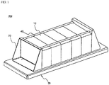
- One of the structures to effectively fix large-capacity unit modules is based on supporting bars and end plates as shown in FIG. 1 .
- a battery module 100 includes unit modules 10, each of which has secondary batteries mounted therein, a base plate 20, a pair of end plates 30, and supporting bars 40.
- the unit modules 10 are stacked at the top of the base plate 20 in a state in which the unit modules 10 are erected vertically.
- the end plates 30 are disposed in tight contact with the outer sides of the outermost unit modules 10 in a state in which the bottom of each of the end plates 30 is fixed to the base plate 20.
- the supporting bars 40 are connected between the upper parts of the end plates 30 so as to interconnect and support the end plates 30.
- the base plate 20 In the structure in which the unit modules 10 are stacked at the top of the plate-shaped base plate 20 in a tight contact fashion, however, strength of the base plate 20 is low with respect to motion in the direction perpendicular to the base plate 20, i.e. the vertical direction. If the base plate 20 does not have vertical strength, the base plate, the base plate 20 may be greatly deformed due to vertical vibration.
- the battery module is installed in a trunk of a vehicle
- a portion of the base plate is mounted above a region where a spare tire is located due to the layout of the vehicle. That is, the battery module is installed in an asymmetrical structure. If vibration from the vehicle due to a road surface is severe, twisting load is applied to the battery module, and such twisting load is transmitted to the base plate with the result that the base plate may be easily damaged.
- JP2001283938 discloses to provide a power source that can suppress temperature gradient in the direction of the air flow in the relatively airtight gas inlet passage, formed between the bottom face of each battery cell and the case.
- the present invention has been made to solve the above problems, and other technical problems that have yet to be resolved.
- a battery module configured to have a structure in which a base plate, at which unit modules are mounted, is provided with an upward protrusion of a specific structure to stably support the unit modules.
- the upper protrusions are formed at the opposite sides of the top of the base plate so that the upper protrusions extend in the longitudinal direction of the base plate, thereby preventing the battery module from being deformed due to vertical vibration applied to the battery module and improving mechanical strength of the battery module.
- each of the unit modules may be a secondary battery or a small-sized module having two or more secondary batteries mounted therein.
- An example of a unit module having two or more secondary batteries mounted therein is disclosed in Korean Patent Application No. 2006-12303 , which has been filed in the name of the applicant of the present application.
- the unit module is configured to have a structure in which two secondary batteries are mounted to a frame member having input and output terminals in a state in which the secondary batteries are in tight contact with each other.
- the unit module is configured to have a structure in which outer sides of two secondary batteries are covered with a pair of high-strength cell covers in a state in which the secondary batteries are in tight contact with each other.
- each of the unit modules of the battery module according to the present invention is not limited to the above examples of the unit modules disclosed in the above patent applications.
- each of the upper protrusions may include an upper side part, with which the bottom of each of the secondary batteries or the unit modules comes into contact, and an inner side part and an outer side part vertically connected between the upper side part and a main body of the base plate.
- each of the upper protrusions includes an upper side part to support the unit modules when the unit modules are vertically stacked and an inner side part and an outer side part vertically connected between the upper side part and the base plate. Consequently, it is possible for the upper protrusions to greatly offset vibration generated in the direction perpendicular to the base plate.
- the upper protrusions are configured to have a shape corresponding to the inner bottom of a vehicle frame constituting a framework of a vehicle. When the battery module is installed in the vehicle, therefore, stability of the battery module is further improved.
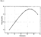
- the inventors of the present invention have found that, if a width x of the upper side part of each of the upper protrusions is not optimized although the upper protrusions are formed at the base plate, it is not possible to sufficiently secure strength of the battery module.
- FIG. 6 is a graph showing an initial resonance frequency based on the size of the upper area of each of the upward protrusions.
- an initial resonance frequency increases as the size of the upper area of each of the upward protrusions increases. Consequently, it can be seen that vibration resistance is relatively high although vibration is generated depending upon a load surface. On the other hand, it can be seen that, if the size of the upper area of each of the upward protrusions is greater than approximately 52 mm, the initial resonance frequency suddenly decreases. This means that deformation and stress may be changed depending upon the size of the upper area of each of the upward protrusions increases, which is an unexpected result.
- the battery module according to the present invention is characterized in that the upper side part has a width x decided by area moment of inertia in a direction perpendicular to a direction in which the secondary batteries or the unit modules are stacked.
- the width x of the upper side part may be decided within a range satisfying conditions of Equation (1) below on the basis of a width w max when area moment of inertia becomes the maximum with respect to the area.
- 'when area moment of inertia becomes the maximum' means when a resistance value with respect to load of each of the unit modules becomes the greatest and when load (drooping) of the upper side part becomes the minimum.
- the reason that the width x of the upper side part is decided within 50% and 150% of the width w max when the area moment of inertia becomes the maximum is that, if the base plate is not completely symmetric or if the edge of the base plate is filleted, the actual maximum value of the width x of the upper side part may differ from the equation.
- the width w max when the area moment of inertia becomes the maximum may be calculated by the following equations.
- h indicates a height of the inner side part or the outer side part
- t indicates a thickness of each of the upper protrusions
- d indicates a length from the middle to the inner side part of the base plate.
- the width (x) of the upper side part may be equivalent to 20% to 50% of a width L from the middle to the shortest side of the base plate in a lateral direction of the base plate (0.2L ⁇ x ⁇ 0.5L).
- the width x of the upper side part is too small, it may be difficult to sufficiently support the unit modules. On the other hand, if the width x of the upper side part is too large, an effect of offsetting vertical vibration decreases and it is not possible to disperse load.
- the base plate may be further provided with one or more auxiliary protrusions connected between the upper protrusions in a lateral direction of the base plate.
- the auxiliary protrusions may be formed at the front end and the rear end of the base plate.
- This structure is advantageous in that it is possible to increase the area of the regions where the end plates are fixed, thereby effectively supporting bending load, minimizing deformation of the base plate due to vertical vibration with the result that it is possible to considerably improve overall dynamic stability of the battery module, as compared with the structure in which only the upper protrusions are formed at the base plate.
- each of the auxiliary protrusions has a width equivalent to 50 to 200% of a width of each of the upper protrusions and has a height equivalent to 40 to 100% of a height of each of the upper protrusions.
- width and height are within the above-defined range, it is possible to further support bending load with respect to the unit modules.
- each of the auxiliary protrusions has a width equivalent to 80 to 150% of a width of each of the upper protrusions and has a height equivalent to 50 to 80% of a height of each of the upper protrusions.
- the edge of the base plate may be filleted to prevent stress from concentrating upon the edge of the base plate.
- the edge of the base plate is finished to have such a fillet structure, and therefore, it is possible to minimize concentration of stress upon the edge of the base plate.
- the base plate is configured to have a structure in which the inner side part of each of the upward protrusions has a height less than that of the outer side part of each of the upward protrusions so that the shape of the base plate corresponds to that of a region of the vehicle where a trunk is mounted, thereby achieving stable installation of the battery module in the vehicle and minimizing the volume of the battery module in the vehicle.
- a device such as an electric vehicle, hybrid electric vehicle, or plug-in hybrid electric vehicle using the battery module with the above-stated construction as a power source, having a limited installation space, and exposed to frequent vibration and strong impact.
- the battery module used as the power source of the vehicle may be combined and manufactured based on desired power and capacity.
- the vehicle may be an electric vehicle, hybrid electric vehicle, or plug-in hybrid electric vehicle wherein the battery module is installed in a trunk of the vehicle.
- the electric vehicle, hybrid electric vehicle, or plug-in hybrid electric vehicle using the battery module as the power source thereof are well known in the art to which the present invention pertains, and therefore, a detailed description thereof will not be given.
- the battery module according to the present invention is configured in a specific structure in which end plates are not deformed and have increasing resistance to stress upon application of bending load. Consequently, it is possible to stably maintain a stacked structure of unit modules each having secondary batteries mounted therein and to minimize damage to bent portions or coupling regions of the end plates.
- a portion of the structure of the battery module is formed using a portion of the shape of a vehicle. Consequently, the battery module is stably installed in the vehicle, and volume of the battery module in the vehicle is minimized.
- FIG. 2 is a perspective view typically showing a battery module according to an embodiment of the present invention.
- the battery module 200 includes unit modules 10, each of which has secondary batteries mounted therein, a base plate 300, a pair of end plates 30, and a pair of supporting bars 40.
- the unit modules 10 are stacked on the top of the base plate 300 in a state in which the unit modules 10 are erected vertically.
- the end plates 30 are disposed in tight contact with the outer sides of the outermost unit modules 10 in a state in which the bottoms of the end plates 30 are fixed to the base plate 200.
- the supporting bars 40 are connected between the upper parts of the end plates 30 so as to support the end plates 30.
- the base plate 300 is provided at opposite sides thereof with a pair of upward protrusions 310, which extends in the longitudinal direction A of the base plate 300. Opposite sides of the bottom of each of the unit modules 10 are disposed at the top of the upward protrusions 310.
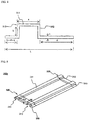
- FIG. 3 is a perspective view typically showing the base plate of FIG. 2
- FIG. 4 is an enlarged sectional view typically showing region B of FIG. 3 .
- each of the upper protrusions 310 of the base plate 300a includes a upper side part 311, with which the bottom of each of the unit modules 10 comes into contact, and an inner side part 312 and an outer side part 313 vertically connected between the upper side part 311 and a main body of the base plate 300a.
- This structure prevents the battery module 200 from being deformed due to vertical vibration and improves mechanical strength of the battery module 200.
- the upper side part 311 of each of the upper protrusions 310 has a width x equivalent to approximately 40% of a width L from the middle to the shortest side of the base plate 300a in the lateral direction of the base plate 300a.
- FIG. 5 is a perspective view showing a base plate according to another embodiment of the present invention.
- the base plate 300b is provided at the front end and the rear end thereof with auxiliary protrusions 320 connected between the upper protrusions 310 in the lateral direction of the base plate 300b.
- Each of the auxiliary protrusions 320 has a width W equivalent to approximately 120% of the width x of each of the upper protrusions 310. Also, each of the auxiliary protrusions 320 has a height H equivalent to approximately 100% of a height h of each of the upper protrusions 310.
- edge of the base plate 300b is filleted to effectively prevent stress generated from the unit modules 10 from concentrating upon the edge of the base plate 300b.
- auxiliary protrusions 320 as well as the upper protrusions 310 are formed at the base plate 300b, therefore, it is possible to increase the area of the regions where the end plates 30 are fixed, thereby effectively supporting bending load, minimizing deformation of the base plate 300b due to vertical vibration. As a result, it is possible to considerably improve overall dynamic stability of the battery module.
Landscapes
- Chemical & Material Sciences (AREA)
- Chemical Kinetics & Catalysis (AREA)
- Electrochemistry (AREA)
- General Chemical & Material Sciences (AREA)
- Engineering & Computer Science (AREA)
- Aviation & Aerospace Engineering (AREA)
- Battery Mounting, Suspending (AREA)
- Sealing Battery Cases Or Jackets (AREA)
Priority Applications (1)
| Application Number | Priority Date | Filing Date | Title |
|---|---|---|---|
| PL11841694T PL2642552T3 (pl) | 2010-11-15 | 2011-11-02 | Moduł akumulatorowy posiadający lepszą stabilność strukturalną |
Applications Claiming Priority (2)
| Application Number | Priority Date | Filing Date | Title |
|---|---|---|---|
| KR20100113275 | 2010-11-15 | ||
| PCT/KR2011/008270 WO2012067360A2 (ko) | 2010-11-15 | 2011-11-02 | 구조적 안정성이 우수한 전지모듈 |
Publications (3)
| Publication Number | Publication Date |
|---|---|
| EP2642552A2 EP2642552A2 (en) | 2013-09-25 |
| EP2642552A4 EP2642552A4 (en) | 2014-08-20 |
| EP2642552B1 true EP2642552B1 (en) | 2019-01-02 |
Family
ID=46084465
Family Applications (1)
| Application Number | Title | Priority Date | Filing Date |
|---|---|---|---|
| EP11841694.0A Active EP2642552B1 (en) | 2010-11-15 | 2011-11-02 | Battery module having superior structural stability |
Country Status (8)
| Country | Link |
|---|---|
| US (2) | US8808893B2 (enExample) |
| EP (1) | EP2642552B1 (enExample) |
| JP (2) | JP6183904B2 (enExample) |
| KR (1) | KR101266904B1 (enExample) |
| CN (1) | CN103180998B (enExample) |
| PL (1) | PL2642552T3 (enExample) |
| TW (1) | TWI461313B (enExample) |
| WO (1) | WO2012067360A2 (enExample) |
Families Citing this family (22)
| Publication number | Priority date | Publication date | Assignee | Title |
|---|---|---|---|---|
| KR101503983B1 (ko) * | 2012-12-27 | 2015-03-18 | 에이치엘그린파워 주식회사 | 배터리모듈조립체의 하우징 구조 및 하우징 방법 |
| US9440601B2 (en) | 2013-09-06 | 2016-09-13 | Johnson Controls Technology Company | System for providing voltage measurements of battery cells to a PCB within a battery module |
| US9608245B2 (en) | 2014-09-30 | 2017-03-28 | Johnson Controls Technology Company | System for providing structural integrity of a battery module |
| US10632857B2 (en) | 2016-08-17 | 2020-04-28 | Shape Corp. | Battery support and protection structure for a vehicle |
| JP6822046B2 (ja) * | 2016-10-12 | 2021-01-27 | 三菱自動車工業株式会社 | 電池モジュール |
| KR102161627B1 (ko) * | 2016-11-29 | 2020-10-05 | 삼성에스디아이 주식회사 | 이차 전지 |
| EP3566253B1 (en) | 2017-01-04 | 2022-12-28 | Shape Corp. | Battery support structure for a vehicle |
| WO2018213475A1 (en) | 2017-05-16 | 2018-11-22 | Shape Corp. | Polarized battery tray for a vehicle |
| WO2018213306A1 (en) | 2017-05-16 | 2018-11-22 | Shape Corp. | Vehicle battery tray having tub-based component |
| WO2018213383A1 (en) | 2017-05-16 | 2018-11-22 | Shape Corp. | Vehicle battery tray with integrated battery retention and support features |
| US10549706B2 (en) | 2017-06-22 | 2020-02-04 | Ford Global Technologies, Llc | Battery pack mounting assembly |
| US12347879B2 (en) | 2017-09-13 | 2025-07-01 | Shape Corp. | Vehicle battery tray with tubular peripheral wall |
| US11088412B2 (en) | 2017-09-13 | 2021-08-10 | Shape Corp. | Vehicle battery tray with tubular peripheral wall |
| US10661646B2 (en) | 2017-10-04 | 2020-05-26 | Shape Corp. | Battery tray floor assembly for electric vehicles |
| CN112055898A (zh) | 2018-03-01 | 2020-12-08 | 形状集团 | 与车辆电池托盘集成的冷却系统 |
| US11688910B2 (en) | 2018-03-15 | 2023-06-27 | Shape Corp. | Vehicle battery tray having tub-based component |
| KR102575355B1 (ko) * | 2018-04-26 | 2023-09-07 | 현대자동차주식회사 | 차량용 배터리 케이스 |
| CN109728221A (zh) * | 2018-12-29 | 2019-05-07 | 蜂巢能源科技有限公司 | 电池包内电芯的固定装置以及电池包 |
| JP7151600B2 (ja) * | 2019-04-09 | 2022-10-12 | トヨタ自動車株式会社 | 蓄電装置 |
| KR102468618B1 (ko) | 2019-06-12 | 2022-11-17 | 주식회사 엘지에너지솔루션 | 전지 모듈, 이의 제조 방법 및 전지팩 |
| CN111162220A (zh) * | 2020-01-20 | 2020-05-15 | 威睿电动汽车技术(宁波)有限公司 | 一种堆叠结构的电池系统 |
| JP7380628B2 (ja) * | 2021-03-31 | 2023-11-15 | トヨタ自動車株式会社 | 電池モジュール |
Family Cites Families (24)
| Publication number | Priority date | Publication date | Assignee | Title |
|---|---|---|---|---|
| JP4837155B2 (ja) * | 1998-11-27 | 2011-12-14 | パナソニック株式会社 | 蓄電池 |
| JP2000195504A (ja) | 1998-12-24 | 2000-07-14 | Sony Corp | ポリマ電池用電極材製造装置 |
| JP4572019B2 (ja) * | 1999-10-08 | 2010-10-27 | パナソニック株式会社 | 組電池 |
| JP4965012B2 (ja) * | 1999-12-15 | 2012-07-04 | トヨタ自動車株式会社 | 車両用電池パック |
| JP4581177B2 (ja) * | 2000-04-03 | 2010-11-17 | トヨタ自動車株式会社 | 電源装置 |
| US6451475B1 (en) * | 2000-07-05 | 2002-09-17 | East Penn Manufacturing Company, Inc. | Front access interlocking modular cell tray assembly |
| JP2002141036A (ja) | 2000-11-06 | 2002-05-17 | Toyota Motor Corp | 集合電池 |
| JP4136328B2 (ja) * | 2001-05-14 | 2008-08-20 | トヨタ自動車株式会社 | バッテリ拘束装置 |
| US6773846B2 (en) * | 2002-08-19 | 2004-08-10 | Allis Electric Co., Ltd. | Mobile rack type battery box for UPS system |
| JP2005149837A (ja) * | 2003-11-13 | 2005-06-09 | Toyota Motor Corp | 電池構造 |
| KR100612303B1 (ko) | 2004-06-03 | 2006-08-11 | 삼성에스디아이 주식회사 | 액정 표시 장치 및 그 감마 보정 방법 |
| JP2006040753A (ja) | 2004-07-28 | 2006-02-09 | Nissan Motor Co Ltd | 車両搭載型燃料電池 |
| KR100669333B1 (ko) * | 2005-01-25 | 2007-01-15 | 삼성에스디아이 주식회사 | 이차 전지 모듈 |
| KR100861713B1 (ko) | 2006-02-09 | 2008-10-06 | 주식회사 엘지화학 | 전지모듈 |
| KR100919390B1 (ko) * | 2006-02-13 | 2009-09-29 | 주식회사 엘지화학 | 수직 적층 구조의 중대형 전지모듈 |
| KR100948002B1 (ko) | 2006-03-06 | 2010-03-18 | 주식회사 엘지화학 | 중대형 전지모듈 |
| KR100870457B1 (ko) | 2006-05-22 | 2008-11-25 | 주식회사 엘지화학 | 전지모듈 |
| JP2008311012A (ja) | 2007-06-13 | 2008-12-25 | Toyota Motor Corp | 燃料電池用電極材料接合体の製造装置および製造方法、燃料電池 |
| KR101029838B1 (ko) * | 2007-06-28 | 2011-04-15 | 주식회사 엘지화학 | 냉각 효율이 향상된 중대형 전지팩 |
| KR101087036B1 (ko) * | 2008-12-17 | 2011-11-25 | 주식회사 엘지화학 | 전극단자 연결장치 및 이를 포함하는 전지모듈 어셈블리 |
| TWM375977U (en) * | 2009-08-05 | 2010-03-11 | Arima Ecoenergy Technologies Corp | Strengthened backboard structure and solar cells applicable thereof |
| WO2011020093A2 (en) * | 2009-08-14 | 2011-02-17 | Dmfcwbs, Llc | Improved structural framing member |
| EP2490276B1 (en) * | 2009-10-13 | 2016-12-07 | LG Chem, Ltd. | Battery module with superior structural stability |
| KR101224496B1 (ko) * | 2010-02-04 | 2013-01-21 | 주식회사 엘지화학 | 보강부재를 포함하고 있는 전지팩 |
-
2011
- 2011-11-02 KR KR1020110113136A patent/KR101266904B1/ko active Active
- 2011-11-02 PL PL11841694T patent/PL2642552T3/pl unknown
- 2011-11-02 JP JP2013538630A patent/JP6183904B2/ja active Active
- 2011-11-02 WO PCT/KR2011/008270 patent/WO2012067360A2/ko not_active Ceased
- 2011-11-02 EP EP11841694.0A patent/EP2642552B1/en active Active
- 2011-11-02 US US13/878,723 patent/US8808893B2/en active Active
- 2011-11-02 CN CN201180050952.9A patent/CN103180998B/zh active Active
- 2011-11-04 TW TW100140351A patent/TWI461313B/zh active
-
2013
- 2013-09-25 US US14/036,363 patent/US10622599B2/en active Active
-
2015
- 2015-09-01 JP JP2015171893A patent/JP6134991B2/ja active Active
Non-Patent Citations (1)
| Title |
|---|
| None * |
Also Published As
| Publication number | Publication date |
|---|---|
| US20140093770A1 (en) | 2014-04-03 |
| EP2642552A4 (en) | 2014-08-20 |
| US8808893B2 (en) | 2014-08-19 |
| JP6134991B2 (ja) | 2017-05-31 |
| CN103180998B (zh) | 2016-01-20 |
| KR101266904B1 (ko) | 2013-05-24 |
| TW201231320A (en) | 2012-08-01 |
| JP6183904B2 (ja) | 2017-08-23 |
| CN103180998A (zh) | 2013-06-26 |
| US10622599B2 (en) | 2020-04-14 |
| JP2013542577A (ja) | 2013-11-21 |
| WO2012067360A2 (ko) | 2012-05-24 |
| WO2012067360A3 (ko) | 2012-07-19 |
| EP2642552A2 (en) | 2013-09-25 |
| JP2016026372A (ja) | 2016-02-12 |
| US20130288095A1 (en) | 2013-10-31 |
| PL2642552T3 (pl) | 2019-06-28 |
| TWI461313B (zh) | 2014-11-21 |
| KR20120052155A (ko) | 2012-05-23 |
Similar Documents
| Publication | Publication Date | Title |
|---|---|---|
| EP2642552B1 (en) | Battery module having superior structural stability | |
| EP2490276B1 (en) | Battery module with superior structural stability | |
| EP2533320B1 (en) | Battery pack with a reinforcing member | |
| EP2682999B1 (en) | Battery pack having excellent structural reliability | |
| EP2530765B1 (en) | Battery pack having outstanding structural stability | |
| EP2634834A2 (en) | Battery pack having improved durability | |
| CN211907564U (zh) | 一种电池电极连接结构及电池模组 | |
| KR101293643B1 (ko) | 패치 플레이트가 장착되어 있는 전지모듈 |
Legal Events
| Date | Code | Title | Description |
|---|---|---|---|
| PUAI | Public reference made under article 153(3) epc to a published international application that has entered the european phase |
Free format text: ORIGINAL CODE: 0009012 |
|
| 17P | Request for examination filed |
Effective date: 20130408 |
|
| AK | Designated contracting states |
Kind code of ref document: A2 Designated state(s): AL AT BE BG CH CY CZ DE DK EE ES FI FR GB GR HR HU IE IS IT LI LT LU LV MC MK MT NL NO PL PT RO RS SE SI SK SM TR |
|
| DAX | Request for extension of the european patent (deleted) | ||
| A4 | Supplementary search report drawn up and despatched |
Effective date: 20140721 |
|
| RIC1 | Information provided on ipc code assigned before grant |
Ipc: H01M 2/10 20060101AFI20140714BHEP Ipc: H01M 2/20 20060101ALI20140714BHEP |
|
| STAA | Information on the status of an ep patent application or granted ep patent |
Free format text: STATUS: EXAMINATION IS IN PROGRESS |
|
| 17Q | First examination report despatched |
Effective date: 20180206 |
|
| GRAP | Despatch of communication of intention to grant a patent |
Free format text: ORIGINAL CODE: EPIDOSNIGR1 |
|
| STAA | Information on the status of an ep patent application or granted ep patent |
Free format text: STATUS: GRANT OF PATENT IS INTENDED |
|
| INTG | Intention to grant announced |
Effective date: 20180820 |
|
| RAP1 | Party data changed (applicant data changed or rights of an application transferred) |
Owner name: LG CHEM, LTD. |
|
| RIN1 | Information on inventor provided before grant (corrected) |
Inventor name: IM, YE HOON Inventor name: CHOO, YEON SEOK Inventor name: PARK, HYUN CHUL Inventor name: LEE, JIN KYU Inventor name: PARK, JUNG MIN |
|
| GRAS | Grant fee paid |
Free format text: ORIGINAL CODE: EPIDOSNIGR3 |
|
| GRAA | (expected) grant |
Free format text: ORIGINAL CODE: 0009210 |
|
| STAA | Information on the status of an ep patent application or granted ep patent |
Free format text: STATUS: THE PATENT HAS BEEN GRANTED |
|
| AK | Designated contracting states |
Kind code of ref document: B1 Designated state(s): AL AT BE BG CH CY CZ DE DK EE ES FI FR GB GR HR HU IE IS IT LI LT LU LV MC MK MT NL NO PL PT RO RS SE SI SK SM TR |
|
| REG | Reference to a national code |
Ref country code: GB Ref legal event code: FG4D |
|
| REG | Reference to a national code |
Ref country code: CH Ref legal event code: EP Ref country code: AT Ref legal event code: REF Ref document number: 1085513 Country of ref document: AT Kind code of ref document: T Effective date: 20190115 |
|
| REG | Reference to a national code |
Ref country code: IE Ref legal event code: FG4D |
|
| REG | Reference to a national code |
Ref country code: DE Ref legal event code: R096 Ref document number: 602011055449 Country of ref document: DE |
|
| REG | Reference to a national code |
Ref country code: NL Ref legal event code: MP Effective date: 20190102 |
|
| REG | Reference to a national code |
Ref country code: LT Ref legal event code: MG4D |
|
| REG | Reference to a national code |
Ref country code: AT Ref legal event code: MK05 Ref document number: 1085513 Country of ref document: AT Kind code of ref document: T Effective date: 20190102 |
|
| PG25 | Lapsed in a contracting state [announced via postgrant information from national office to epo] |
Ref country code: NL Free format text: LAPSE BECAUSE OF FAILURE TO SUBMIT A TRANSLATION OF THE DESCRIPTION OR TO PAY THE FEE WITHIN THE PRESCRIBED TIME-LIMIT Effective date: 20190102 |
|
| PG25 | Lapsed in a contracting state [announced via postgrant information from national office to epo] |
Ref country code: NO Free format text: LAPSE BECAUSE OF FAILURE TO SUBMIT A TRANSLATION OF THE DESCRIPTION OR TO PAY THE FEE WITHIN THE PRESCRIBED TIME-LIMIT Effective date: 20190402 Ref country code: PT Free format text: LAPSE BECAUSE OF FAILURE TO SUBMIT A TRANSLATION OF THE DESCRIPTION OR TO PAY THE FEE WITHIN THE PRESCRIBED TIME-LIMIT Effective date: 20190502 Ref country code: FI Free format text: LAPSE BECAUSE OF FAILURE TO SUBMIT A TRANSLATION OF THE DESCRIPTION OR TO PAY THE FEE WITHIN THE PRESCRIBED TIME-LIMIT Effective date: 20190102 Ref country code: SE Free format text: LAPSE BECAUSE OF FAILURE TO SUBMIT A TRANSLATION OF THE DESCRIPTION OR TO PAY THE FEE WITHIN THE PRESCRIBED TIME-LIMIT Effective date: 20190102 Ref country code: LT Free format text: LAPSE BECAUSE OF FAILURE TO SUBMIT A TRANSLATION OF THE DESCRIPTION OR TO PAY THE FEE WITHIN THE PRESCRIBED TIME-LIMIT Effective date: 20190102 Ref country code: ES Free format text: LAPSE BECAUSE OF FAILURE TO SUBMIT A TRANSLATION OF THE DESCRIPTION OR TO PAY THE FEE WITHIN THE PRESCRIBED TIME-LIMIT Effective date: 20190102 |
|
| PG25 | Lapsed in a contracting state [announced via postgrant information from national office to epo] |
Ref country code: RS Free format text: LAPSE BECAUSE OF FAILURE TO SUBMIT A TRANSLATION OF THE DESCRIPTION OR TO PAY THE FEE WITHIN THE PRESCRIBED TIME-LIMIT Effective date: 20190102 Ref country code: HR Free format text: LAPSE BECAUSE OF FAILURE TO SUBMIT A TRANSLATION OF THE DESCRIPTION OR TO PAY THE FEE WITHIN THE PRESCRIBED TIME-LIMIT Effective date: 20190102 Ref country code: LV Free format text: LAPSE BECAUSE OF FAILURE TO SUBMIT A TRANSLATION OF THE DESCRIPTION OR TO PAY THE FEE WITHIN THE PRESCRIBED TIME-LIMIT Effective date: 20190102 Ref country code: GR Free format text: LAPSE BECAUSE OF FAILURE TO SUBMIT A TRANSLATION OF THE DESCRIPTION OR TO PAY THE FEE WITHIN THE PRESCRIBED TIME-LIMIT Effective date: 20190403 Ref country code: IS Free format text: LAPSE BECAUSE OF FAILURE TO SUBMIT A TRANSLATION OF THE DESCRIPTION OR TO PAY THE FEE WITHIN THE PRESCRIBED TIME-LIMIT Effective date: 20190502 Ref country code: BG Free format text: LAPSE BECAUSE OF FAILURE TO SUBMIT A TRANSLATION OF THE DESCRIPTION OR TO PAY THE FEE WITHIN THE PRESCRIBED TIME-LIMIT Effective date: 20190402 |
|
| REG | Reference to a national code |
Ref country code: DE Ref legal event code: R097 Ref document number: 602011055449 Country of ref document: DE |
|
| PG25 | Lapsed in a contracting state [announced via postgrant information from national office to epo] |
Ref country code: EE Free format text: LAPSE BECAUSE OF FAILURE TO SUBMIT A TRANSLATION OF THE DESCRIPTION OR TO PAY THE FEE WITHIN THE PRESCRIBED TIME-LIMIT Effective date: 20190102 Ref country code: DK Free format text: LAPSE BECAUSE OF FAILURE TO SUBMIT A TRANSLATION OF THE DESCRIPTION OR TO PAY THE FEE WITHIN THE PRESCRIBED TIME-LIMIT Effective date: 20190102 Ref country code: IT Free format text: LAPSE BECAUSE OF FAILURE TO SUBMIT A TRANSLATION OF THE DESCRIPTION OR TO PAY THE FEE WITHIN THE PRESCRIBED TIME-LIMIT Effective date: 20190102 Ref country code: RO Free format text: LAPSE BECAUSE OF FAILURE TO SUBMIT A TRANSLATION OF THE DESCRIPTION OR TO PAY THE FEE WITHIN THE PRESCRIBED TIME-LIMIT Effective date: 20190102 Ref country code: AT Free format text: LAPSE BECAUSE OF FAILURE TO SUBMIT A TRANSLATION OF THE DESCRIPTION OR TO PAY THE FEE WITHIN THE PRESCRIBED TIME-LIMIT Effective date: 20190102 Ref country code: AL Free format text: LAPSE BECAUSE OF FAILURE TO SUBMIT A TRANSLATION OF THE DESCRIPTION OR TO PAY THE FEE WITHIN THE PRESCRIBED TIME-LIMIT Effective date: 20190102 Ref country code: CZ Free format text: LAPSE BECAUSE OF FAILURE TO SUBMIT A TRANSLATION OF THE DESCRIPTION OR TO PAY THE FEE WITHIN THE PRESCRIBED TIME-LIMIT Effective date: 20190102 Ref country code: SK Free format text: LAPSE BECAUSE OF FAILURE TO SUBMIT A TRANSLATION OF THE DESCRIPTION OR TO PAY THE FEE WITHIN THE PRESCRIBED TIME-LIMIT Effective date: 20190102 |
|
| PLBE | No opposition filed within time limit |
Free format text: ORIGINAL CODE: 0009261 |
|
| STAA | Information on the status of an ep patent application or granted ep patent |
Free format text: STATUS: NO OPPOSITION FILED WITHIN TIME LIMIT |
|
| PG25 | Lapsed in a contracting state [announced via postgrant information from national office to epo] |
Ref country code: SM Free format text: LAPSE BECAUSE OF FAILURE TO SUBMIT A TRANSLATION OF THE DESCRIPTION OR TO PAY THE FEE WITHIN THE PRESCRIBED TIME-LIMIT Effective date: 20190102 |
|
| 26N | No opposition filed |
Effective date: 20191003 |
|
| PG25 | Lapsed in a contracting state [announced via postgrant information from national office to epo] |
Ref country code: SI Free format text: LAPSE BECAUSE OF FAILURE TO SUBMIT A TRANSLATION OF THE DESCRIPTION OR TO PAY THE FEE WITHIN THE PRESCRIBED TIME-LIMIT Effective date: 20190102 |
|
| PG25 | Lapsed in a contracting state [announced via postgrant information from national office to epo] |
Ref country code: TR Free format text: LAPSE BECAUSE OF FAILURE TO SUBMIT A TRANSLATION OF THE DESCRIPTION OR TO PAY THE FEE WITHIN THE PRESCRIBED TIME-LIMIT Effective date: 20190102 |
|
| REG | Reference to a national code |
Ref country code: CH Ref legal event code: PL |
|
| PG25 | Lapsed in a contracting state [announced via postgrant information from national office to epo] |
Ref country code: CH Free format text: LAPSE BECAUSE OF NON-PAYMENT OF DUE FEES Effective date: 20191130 Ref country code: MC Free format text: LAPSE BECAUSE OF FAILURE TO SUBMIT A TRANSLATION OF THE DESCRIPTION OR TO PAY THE FEE WITHIN THE PRESCRIBED TIME-LIMIT Effective date: 20190102 Ref country code: LI Free format text: LAPSE BECAUSE OF NON-PAYMENT OF DUE FEES Effective date: 20191130 Ref country code: LU Free format text: LAPSE BECAUSE OF NON-PAYMENT OF DUE FEES Effective date: 20191102 |
|
| REG | Reference to a national code |
Ref country code: BE Ref legal event code: MM Effective date: 20191130 |
|
| PG25 | Lapsed in a contracting state [announced via postgrant information from national office to epo] |
Ref country code: IE Free format text: LAPSE BECAUSE OF NON-PAYMENT OF DUE FEES Effective date: 20191102 |
|
| REG | Reference to a national code |
Ref country code: DE Ref legal event code: R079 Ref document number: 602011055449 Country of ref document: DE Free format text: PREVIOUS MAIN CLASS: H01M0002100000 Ipc: H01M0050200000 |
|
| PG25 | Lapsed in a contracting state [announced via postgrant information from national office to epo] |
Ref country code: BE Free format text: LAPSE BECAUSE OF NON-PAYMENT OF DUE FEES Effective date: 20191130 |
|
| PG25 | Lapsed in a contracting state [announced via postgrant information from national office to epo] |
Ref country code: CY Free format text: LAPSE BECAUSE OF FAILURE TO SUBMIT A TRANSLATION OF THE DESCRIPTION OR TO PAY THE FEE WITHIN THE PRESCRIBED TIME-LIMIT Effective date: 20190102 |
|
| PG25 | Lapsed in a contracting state [announced via postgrant information from national office to epo] |
Ref country code: MT Free format text: LAPSE BECAUSE OF FAILURE TO SUBMIT A TRANSLATION OF THE DESCRIPTION OR TO PAY THE FEE WITHIN THE PRESCRIBED TIME-LIMIT Effective date: 20190102 Ref country code: HU Free format text: LAPSE BECAUSE OF FAILURE TO SUBMIT A TRANSLATION OF THE DESCRIPTION OR TO PAY THE FEE WITHIN THE PRESCRIBED TIME-LIMIT; INVALID AB INITIO Effective date: 20111102 |
|
| PG25 | Lapsed in a contracting state [announced via postgrant information from national office to epo] |
Ref country code: MK Free format text: LAPSE BECAUSE OF FAILURE TO SUBMIT A TRANSLATION OF THE DESCRIPTION OR TO PAY THE FEE WITHIN THE PRESCRIBED TIME-LIMIT Effective date: 20190102 |
|
| P01 | Opt-out of the competence of the unified patent court (upc) registered |
Effective date: 20230323 |
|
| REG | Reference to a national code |
Ref country code: DE Ref legal event code: R081 Ref document number: 602011055449 Country of ref document: DE Owner name: LG ENERGY SOLUTION, LTD., KR Free format text: FORMER OWNER: LG CHEM, LTD., SEOUL, KR |
|
| REG | Reference to a national code |
Ref country code: GB Ref legal event code: 732E Free format text: REGISTERED BETWEEN 20230824 AND 20230831 |
|
| PGFP | Annual fee paid to national office [announced via postgrant information from national office to epo] |
Ref country code: DE Payment date: 20241021 Year of fee payment: 14 |
|
| PGFP | Annual fee paid to national office [announced via postgrant information from national office to epo] |
Ref country code: PL Payment date: 20241022 Year of fee payment: 14 |
|
| PGFP | Annual fee paid to national office [announced via postgrant information from national office to epo] |
Ref country code: GB Payment date: 20241022 Year of fee payment: 14 |
|
| PGFP | Annual fee paid to national office [announced via postgrant information from national office to epo] |
Ref country code: FR Payment date: 20241022 Year of fee payment: 14 |