EP2642266A1 - Leak detector - Google Patents
Leak detector Download PDFInfo
- Publication number
- EP2642266A1 EP2642266A1 EP11841122.2A EP11841122A EP2642266A1 EP 2642266 A1 EP2642266 A1 EP 2642266A1 EP 11841122 A EP11841122 A EP 11841122A EP 2642266 A1 EP2642266 A1 EP 2642266A1
- Authority
- EP
- European Patent Office
- Prior art keywords
- intake port
- test piece
- mass spectrometer
- turbo
- leak
- Prior art date
- Legal status (The legal status is an assumption and is not a legal conclusion. Google has not performed a legal analysis and makes no representation as to the accuracy of the status listed.)
- Withdrawn
Links
Images


Classifications
-
- G—PHYSICS
- G01—MEASURING; TESTING
- G01M—TESTING STATIC OR DYNAMIC BALANCE OF MACHINES OR STRUCTURES; TESTING OF STRUCTURES OR APPARATUS, NOT OTHERWISE PROVIDED FOR
- G01M3/00—Investigating fluid-tightness of structures
- G01M3/02—Investigating fluid-tightness of structures by using fluid or vacuum
- G01M3/04—Investigating fluid-tightness of structures by using fluid or vacuum by detecting the presence of fluid at the leakage point
- G01M3/20—Investigating fluid-tightness of structures by using fluid or vacuum by detecting the presence of fluid at the leakage point using special tracer materials, e.g. dye, fluorescent material, radioactive material
- G01M3/202—Investigating fluid-tightness of structures by using fluid or vacuum by detecting the presence of fluid at the leakage point using special tracer materials, e.g. dye, fluorescent material, radioactive material using mass spectrometer detection systems
- G01M3/205—Accessories or associated equipment; Pump constructions
-
- F—MECHANICAL ENGINEERING; LIGHTING; HEATING; WEAPONS; BLASTING
- F04—POSITIVE - DISPLACEMENT MACHINES FOR LIQUIDS; PUMPS FOR LIQUIDS OR ELASTIC FLUIDS
- F04D—NON-POSITIVE-DISPLACEMENT PUMPS
- F04D19/00—Axial-flow pumps
- F04D19/02—Multi-stage pumps
- F04D19/04—Multi-stage pumps specially adapted to the production of a high vacuum, e.g. molecular pumps
-
- F—MECHANICAL ENGINEERING; LIGHTING; HEATING; WEAPONS; BLASTING
- F04—POSITIVE - DISPLACEMENT MACHINES FOR LIQUIDS; PUMPS FOR LIQUIDS OR ELASTIC FLUIDS
- F04D—NON-POSITIVE-DISPLACEMENT PUMPS
- F04D19/00—Axial-flow pumps
- F04D19/02—Multi-stage pumps
- F04D19/04—Multi-stage pumps specially adapted to the production of a high vacuum, e.g. molecular pumps
- F04D19/042—Turbomolecular vacuum pumps
-
- G—PHYSICS
- G01—MEASURING; TESTING
- G01M—TESTING STATIC OR DYNAMIC BALANCE OF MACHINES OR STRUCTURES; TESTING OF STRUCTURES OR APPARATUS, NOT OTHERWISE PROVIDED FOR
- G01M3/00—Investigating fluid-tightness of structures
- G01M3/02—Investigating fluid-tightness of structures by using fluid or vacuum
- G01M3/04—Investigating fluid-tightness of structures by using fluid or vacuum by detecting the presence of fluid at the leakage point
- G01M3/20—Investigating fluid-tightness of structures by using fluid or vacuum by detecting the presence of fluid at the leakage point using special tracer materials, e.g. dye, fluorescent material, radioactive material
Definitions
- a leak detector is conventionally known to be used for leak detection (a leak test) to detect whether a test piece, such as an airtight container, a pipe, or a valve, has a minute leak or not.
- a generally-used leak detector of this type includes: a mass spectrometer tube which can quantitatively detect, as an ionic current, a search gas leaking in vacuum; a turbo-molecule pump which has a plurality of stages of rotors and stators alternately arranged in a housing, the rotor being attached to a rotary shaft, and which includes a drive source configured to rotationally drive the rotary shaft; and a fore pump provided on the back pressure side of the turbo-molecule pump.
- a mass spectrometer tube which can quantitatively detect, as an ionic current, a search gas leaking in vacuum
- a turbo-molecule pump which has a plurality of stages of rotors and stators alternately arranged in a housing, the rotor being attached to a rotary shaft, and which includes
- Patent Document 1 Japanese Patent No. 2655315
- the leak test starts when a vacuum gauge provided to the connection port reaches a predetermined value, for example.
- helium gas as the search gas is sprayed locally onto the test piece from the outside. If the test piece has a leak, the helium gas is sucked into the test piece, and is guided to the intake port of the turbo-molecule pump through the connection pipe.
- components, such as nitrogen and oxygen which are largely included in the atmosphere have low diffusivity in the space between the above-described inner side of the wall surface and the rotor located at the highest vacuum side, and are therefore discharged by the rotor located at the highest vacuum side.
- the leak detector is configured such that conductance between the intake port and the connection port is 1/10 or less of an effective pumping speed of the intake port. According to this, the intake port and the connection port can have a pressure difference of at least one or more digits therebetween, allowing the leak test to be started quickly after the start of vacuuming the test piece.
- the conductance of the above-described space can be adjusted by appropriately setting the values of, for example, the volume of the space (e.g., the distance between an inner surface of the chassis and the rotor of the uppermost stage), the opening size of each of the connection port and the intake port, and the distance between the hole axes of the connection port and the intake port, in consideration of the pumping speed of the turbo-molecule pump itself or the type of gas used.
- the volume of the space e.g., the distance between an inner surface of the chassis and the rotor of the uppermost stage
- the opening size of each of the connection port and the intake port e.g., the distance between an inner surface of the chassis and the rotor of the uppermost stage
- the opening size of each of the connection port and the intake port e.g., the distance between an inner surface of the chassis and the rotor of the uppermost stage
- the opening size of each of the connection port and the intake port e.g., the distance between an inner surface of the chassis and the rotor
- the leak detector is configured to detect presence of a minute leak from a test piece TP such as an airtight container including a vacuum chamber of a vacuum treatment apparatus, a pipe, or a valve.
- a test piece TP such as an airtight container including a vacuum chamber of a vacuum treatment apparatus, a pipe, or a valve.
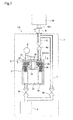
- a leak detector LD includes a chassis 1, and inside the chassis 1, includes a mass spectrometer tube 2, a turbo-molecular pump 3, and a fore pump 4 provided at the back-pressure side of the turbo-molecular pump 3.
- a turbo-molecule pump 3 One having the following configuration can be used as the turbo-molecule pump 3.
- the turbo-molecule pump 3 inside a housing 31, the turbo-molecule pump 3 has a plurality of stages of rotors 33 and stators 34 alternately arranged, the rotors 33 is attached to a rotary shaft 32, and the rotary shaft 32 is rotationally driven by a drive source 35. Descriptions will be given below assuming that the direction from the drive source 35 to the rotors 33 is upward (an up-down direction in Fig. 1 ).
- the wall surface 31a of the housing 31 facing the rotor 33a of the uppermost stage (namely, a top surface of the housing facing the rotor 33a located at the highest vacuum side) is provided with an intake port 36 having a predetermined opening size at a position radially shifted to one side from the axis of the rotary shaft 32 (see Fig. 2 ).
- the intake port 36 is connected with a main passage 5 leading to a flanged port 11 provided in a top surface of the chassis 1.
- An electromagnetic on-off valve 6a is interposingly provided in the main passage 5, and a sub passage 7 is connected to the primary passage 5 at a position between the electromagnetic on-off valve 6a and the port 11.
- FIG. 1 Another electromagnetic on-off valve 6b is interposingly provided in the sub passage 7 which is connected to the fore pump 4.
- Reference numeral 6c in Fig. 1 indicates yet another electromagnetic on-off valve 6c which opens and closes the path between the turbo-molecule pump 3 and the fore pump 4.
- control means including a computer , a sequencer or the like.
- the control means is provided with storage means such as a ROM storing in advance a computation chart for computing a leak value based on the ionic current, a control program (an operation sequence) for the leak detector LD used during a leak test, and the like.
- storage means such as a ROM storing in advance a computation chart for computing a leak value based on the ionic current, a control program (an operation sequence) for the leak detector LD used during a leak test, and the like.
- a description is given below of how the leak detector LD of the present embodiment performs a leak test on the test piece TP using helium as a search gas.
- the turbo-molecule pump 3 and the fore pump 4 are activated to put the leak detector LD in its standby mode.
- the port 11 of the leak detector LD and a test port TP1 of the test piece TP are connected to each other via a connection pipe 8.
- the test piece TP is roughly vacuumed through the connection pipe 8.
- the internal pressure of the sub passage 7 is measured using a Pirani gauge (not shown), and once the test piece TP is vacuumed to a predetermined pressure, the on-off valves 6c, 6a are sequentially opened to vacuum the test piece TP mainly with the turbo-molecule pump 3.
- the intake port 36 and the connection port 37 leading to the mass spectrometer tube 2 are arranged away from each other in the wall surface 31a of the housing 31 of the turbo-molecule pump 3 with a predetermined interval therebetween. Accordingly, conductance of a space S existing between an inner surface of the wall surface 31a and the rotor 33a of the uppermost stage generates a pressure difference between the intake port 36 and the connection port 37 (i.e., the connection port 37 has a lower pressure than the intake port 36).
- the intake port 36 and the connection port 37 can have a pressure difference of at least one or more digits therebetween by making conductance C between the intake port 36 and the connection port 37 which communicate with the space S is a tenth or less of an effective pumping speed S' of the intake port 36.
- the conductance C is 2% or less of the effective pumping speed S' of the intake port, and as a result, the pressure of the connection port 37 can be maintained at 2% or less, namely, 1/50 or less of the pressure of the intake port 36.
- gas can be introduced under a pressure 50 times the operation pressure of the mass spectrometer tube 2.
- the conductance may be reduced as much as possible.
- helium gas is sprayed onto the test piece TP from outside by using a spray gun or the like.
- the helium gas is sucked into the test piece TP through a portion of the leak, passes through the connection pipe 8 and the main passage 5, and then drawn into the turbo-molecule pump 3 through the intake port 36.
- the helium gas as the search gas is lighter than nitrogen and oxygen, therefore has a high average speed after being introduced into the space S, and has high diffusivity. Accordingly, much of the helium gas reach the mass spectrometer tube 2 through the connection port 37. As a result, reliable leak detection with high detection sensitivity can be accomplished without impairing the capabilities such as fast response to helium gas.
- a leak test can be started when the internal pressure of the mass spectrometer tube 2 reaches a pressure which allows measurement operation, irrespective of the pressure of the intake port 36 and further the pressure of the test piece TP. Consequently, compared to the conventional example described earlier, a leak test can be started quickly after the start of vacuuming the test piece. Moreover, reliable leak detection with high detection sensitivity can be accomplished without impairing the capabilities such as fast response to helium gas.
- a leak detector (of the present invention) shown in Fig. 1 , which includes a turbo-molecule pump having a nitrogen-gas pumping speed of 70 L/s, and in which the distance between an intake port and a connection port is 35 mm, and the interval between a wall surface of a housing and a rotor is 1 mm, the pressure of the intake port and the pressure of a mass spectrometer tube were measured.
- Fig. 4 As a comparative experiment, using a (conventional) leak detector shown in Fig. 4 which includes a turbo-molecule pump having a nitrogen-gas pumping speed of 70 L/s, the pressure of the intake port and the pressure of a mass spectrometer tube were measured.
- Fig. 3 shows a graph indicating the pressure relationships between the intake port and the mass spectrometer tube.
- square points indicate the conventional leak detector
- circular points indicate the leak detector of the present invention.
- the mass spectrometer tube and the intake port had almost no pressure difference therebetween because they communicated with each other.
- the leak detector of the present invention that the pressure of the mass spectrometer tube was about 1/100 of the pressure of the intake port, and therefore a pressure difference was effectively generated between the intake port 36 and the connection port 37.
- the present invention is not limited to the above mode.
- the intake port and the connection port do not have to be symmetric to each other, and their positions can be changed appropriately as long as desired conductance can be obtained.
- the present embodiment has been described with an example of the turbo-molecule pump in which each blade constituting the rotors is provided radially outward from the cylindrical rotary shaft.
- the present invention can be applied to a leak detector having a turbo-molecule pump in which the blades constituting the rotors are provided along the generating line of the cylindrical rotary shaft.
- the intake port and the connection port may be opened in a wall surface of the housing of the turbo-molecule pump at positions away from each other, the wall surface being located at the highest vacuum side.
- the leak detector is not limited to such mode.
Landscapes
- Engineering & Computer Science (AREA)
- Physics & Mathematics (AREA)
- General Physics & Mathematics (AREA)
- Mechanical Engineering (AREA)
- General Engineering & Computer Science (AREA)
- Examining Or Testing Airtightness (AREA)
- Non-Positive Displacement Air Blowers (AREA)
Abstract
Description
- The present invention relates to a leak detector, and to a convenient leak detector capable of quickly starting leak detection.
- A leak detector is conventionally known to be used for leak detection (a leak test) to detect whether a test piece, such as an airtight container, a pipe, or a valve, has a minute leak or not. A generally-used leak detector of this type includes: a mass spectrometer tube which can quantitatively detect, as an ionic current, a search gas leaking in vacuum; a turbo-molecule pump which has a plurality of stages of rotors and stators alternately arranged in a housing, the rotor being attached to a rotary shaft, and which includes a drive source configured to rotationally drive the rotary shaft; and a fore pump provided on the back pressure side of the turbo-molecule pump. In such a leak detector, as shown in
Fig. 4 , an end portion of a primary passage b leading to an intake port a1 of a turbo-molecule pump a and a test piece (not shown) are connected to each other through a connection pipe, and a mass spectrometer tube c is interposingly provided in the primary passage b. Such a leak detector is described inPatent Document 1, for example. - The intake port a1 of the turbo-molecule pump a is usually provided facing a rotor a2 of the uppermost stage (i.e., at a position where the turbo-molecule pump a has a highest pumping speed). Since the mass spectrometer tube c is in the primary passage b through which a search gas, such as helium, flows after being introduced into a test port of the test piece, this leak detector has an advantage of having high detection sensitivity and of responding quickly to the helium gas.
- However, this conventional example has the following problem. Specifically, the mass spectrometer tube c and the intake port a1 communicate with each other and therefore have no pressure difference therebetween. Because of this structure, a leak test cannot be started until the pressure of the intake port a1 reaches a pressure which allows the mass spectrometer tube c to perform the measurement operation. Due to this problem, when a test piece is such a large volume as to require a long time to vacuum the inside of the test piece, it takes time to start a leak test. This is very inconvenient.
- Patent Document 1: Japanese Patent No.
2655315 - The present invention has been made in consideration of the above problem, and has an objective to provide a convenient leak detector which has high detection sensitivity and can quickly start a leak test after the start of vacuuming a test piece, without impairing the capabilities such as fast response to helium gas.
- In order to solve the above problem, the present invention provide a leak detector including a mass spectrometer tube configured to detect a search gas and a turbo-molecule pump which has a plurality of stages of rotors and stators alternately arranged in a housing, the rotors attached to a rotary shaft, and which includes a drive source configured to rotationally drive the rotary shaft, an intake port of the turbo-molecule pump being connected to a test piece through a connection pipe, the leak detector configured to perform leak detection by causing the search gas to enter the mass spectrometer tube from inside of the test piece, wherein the intake port communicating with the test piece and a connection port to which the mass spectrometer tube is connected are opened at positions away from each other in a wall surface of the housing, the wall surface facing one of the rotors which is located at a highest vacuum side.
- According to the present invention, prior to a leak test, a test port of the test piece and the intake port of the leak detector (or an end portion of a primary passage extending from the intake port) are connected to each other through the connection pipe. Next, the turbo-molecule pump is activated (generally, a fore pump is provided on the back pressure side of the turbo-molecule pump, and the test piece is roughly vacuumed through this fore pump. If a vacuum pump is provided to the test piece, this vacuum pump may be activated.) to roughly vacuum the test piece. At the same time, the mass spectrometer tube is also vacuumed. In the present invention, the intake port and the connection port are arranged away from each other in the wall surface of the housing of the turbo-molecule pump, the wall surface facing the rotor at the highest vacuum side (e.g., which is, in a case of a turbo-molecular pump in which each blade constituting the rotors extend radially outward from the rotary shaft, a rotor of the uppermost stage, where the direction from the drive source to the rotor is regarded as upward). Accordingly, the conductance of the space between an inner side of the wall surface and the rotor located at the highest vacuum side generates a pressure difference between the intake port and the connection port (i.e., the connection port has a lower pressure than the intake port). Accordingly, once the pressure inside the mass spectrometer tube reaches a pressure which allows measurement operation, a leak test can be started, irrespective of the pressure of the intake port and further the pressure inside the test piece.
- The leak test starts when a vacuum gauge provided to the connection port reaches a predetermined value, for example. Here, helium gas as the search gas is sprayed locally onto the test piece from the outside. If the test piece has a leak, the helium gas is sucked into the test piece, and is guided to the intake port of the turbo-molecule pump through the connection pipe. Here, among the components of the gas introduced from the test piece to the intake port of the turbo-molecule pump, components, such as nitrogen and oxygen, which are largely included in the atmosphere have low diffusivity in the space between the above-described inner side of the wall surface and the rotor located at the highest vacuum side, and are therefore discharged by the rotor located at the highest vacuum side.
- On the other hand, the helium gas or the like generally used as a search gas is lighter than nitrogen and oxygen, and therefore has a high average speed after being introduced into the above-described space. For this reason, the search gas has high diffusivity in this space, so that much of the search gas can reach the mass spectrometer tube through the intake port. As a result, reliable leak detection having high detection sensitivity can be accomplished without impairing the capabilities such as fast response to helium gas.
- In the present invention, the leak detector is configured such that conductance between the intake port and the connection port is 1/10 or less of an effective pumping speed of the intake port. According to this, the intake port and the connection port can have a pressure difference of at least one or more digits therebetween, allowing the leak test to be started quickly after the start of vacuuming the test piece. In this case, the conductance of the above-described space can be adjusted by appropriately setting the values of, for example, the volume of the space (e.g., the distance between an inner surface of the chassis and the rotor of the uppermost stage), the opening size of each of the connection port and the intake port, and the distance between the hole axes of the connection port and the intake port, in consideration of the pumping speed of the turbo-molecule pump itself or the type of gas used.
-
- [
Fig. 1] Fig. 1 is a diagram schematically showing the configuration of a leak detector of the present invention. - [
Fig. 2] Fig. 2 is a cross-sectional view along line II-II ofFig. 1 . - [
Fig. 3] Fig. 3 is a graph showing a result of an experiment. - [
Fig. 4] Fig. 4 is a diagram schematically showing the configuration of a leak detector of a conventional example. - With reference to the drawings, a leak detector according to an embodiment of the present invention is described below. The leak detector is configured to detect presence of a minute leak from a test piece TP such as an airtight container including a vacuum chamber of a vacuum treatment apparatus, a pipe, or a valve.
- Referring to
Figs. 1 and2 , a leak detector LD includes achassis 1, and inside thechassis 1, includes amass spectrometer tube 2, a turbo-molecular pump 3, and afore pump 4 provided at the back-pressure side of the turbo-molecular pump 3. One having the following configuration can be used as the turbo-molecule pump 3. Specifically, inside ahousing 31, the turbo-molecule pump 3 has a plurality of stages ofrotors 33 andstators 34 alternately arranged, therotors 33 is attached to arotary shaft 32, and therotary shaft 32 is rotationally driven by adrive source 35. Descriptions will be given below assuming that the direction from thedrive source 35 to therotors 33 is upward (an up-down direction inFig. 1 ). In this case, when the turbo-molecule pump 3 having the above configuration is in operation, arotor 33a of the uppermost stage is at the highest vacuum side. Note that a known turbo-molecule pump can be used as the turbo-molecule pump 3, but as will be described later, the turbo-molecule pump 3 is different from the known one in that the interval between therotor 33a of the uppermost stage and awall surface 31a of thehousing 31 facing therotor 33a is set to a predetermined value. Further, there is no particular limitation on thefore pump 4 either, and a rotary pump or the like can be used. - The
wall surface 31a of thehousing 31 facing therotor 33a of the uppermost stage (namely, a top surface of the housing facing therotor 33a located at the highest vacuum side) is provided with anintake port 36 having a predetermined opening size at a position radially shifted to one side from the axis of the rotary shaft 32 (seeFig. 2 ). Theintake port 36 is connected with amain passage 5 leading to aflanged port 11 provided in a top surface of thechassis 1. An electromagnetic on-offvalve 6a is interposingly provided in themain passage 5, and asub passage 7 is connected to theprimary passage 5 at a position between the electromagnetic on-offvalve 6a and theport 11. Another electromagnetic on-offvalve 6b is interposingly provided in thesub passage 7 which is connected to thefore pump 4.Reference numeral 6c inFig. 1 indicates yet another electromagnetic on-offvalve 6c which opens and closes the path between the turbo-molecule pump 3 and thefore pump 4. - A
connection port 37 is provided to thewall surface 31a of thehousing 31 at a position symmetric to theintake port 36 with respect to the axis of therotary shaft 32. Themass spectrometer tube 2 is attached to thisconnection port 37. For example, a mass spectrometer tube of magnetic field deflection type can be used as the mass spectrometer tube. In this case, although not particularly illustrated, themass spectrometer tube 2 includes: an ion source which has a filament and a grid and ionizes inside gas components; an ion collector which collects helium ions; and a magnet with which only the helium ions out of positive ions generated by the ion source are attracted to the ion collector. Then, ionic current flowing through the ion collector is detected by an ammeter (not shown) provided along the ion collector. Themass spectrometer tube 2 of the present embodiment is provided with another ion collector around the ion source, which ion collector serves as an ionization vacuum gauge for measuring the total pressure inside themass spectrometer tube 2 as well. Note that themass spectrometer tube 2 is not limited to the above-described one, but can employ other configurations, and further, the vacuum gauge may be provided separately. - Overall control of operations and the like of the parts described above can be performed by control means (not shown) including a computer , a sequencer or the like. In this case, the control means is provided with storage means such as a ROM storing in advance a computation chart for computing a leak value based on the ionic current, a control program (an operation sequence) for the leak detector LD used during a leak test, and the like. A description is given below of how the leak detector LD of the present embodiment performs a leak test on the test piece TP using helium as a search gas.
- First, with only the on-off
valve 6c open and the other on-offvalves molecule pump 3 and thefore pump 4 are activated to put the leak detector LD in its standby mode. In this state, theport 11 of the leak detector LD and a test port TP1 of the test piece TP are connected to each other via aconnection pipe 8. Next, with the on-offvalve 6c closed and the on-offvalve 6b open, the test piece TP is roughly vacuumed through theconnection pipe 8. The internal pressure of thesub passage 7 is measured using a Pirani gauge (not shown), and once the test piece TP is vacuumed to a predetermined pressure, the on-offvalves molecule pump 3. - In the present embodiment, the
intake port 36 and theconnection port 37 leading to themass spectrometer tube 2 are arranged away from each other in thewall surface 31a of thehousing 31 of the turbo-molecule pump 3 with a predetermined interval therebetween. Accordingly, conductance of a space S existing between an inner surface of thewall surface 31a and therotor 33a of the uppermost stage generates a pressure difference between theintake port 36 and the connection port 37 (i.e., theconnection port 37 has a lower pressure than the intake port 36). In this case, theintake port 36 and theconnection port 37 can have a pressure difference of at least one or more digits therebetween by making conductance C between theintake port 36 and theconnection port 37 which communicate with the space S is a tenth or less of an effective pumping speed S' of theintake port 36. - The conductance of the space S can be desirably adjusted by appropriately setting the values of, for example, the volume of the space (so that an interval D between the inner surface of the
housing 31 and therotor 33a of the uppermost stage would preferably be 5 mm or less), the opening size of each of theintake port 36 and the connection port 37 (e.g., 7 mm or above for a port having a pumping speed of 70L/s for example), a distance L between the hole axes of theintake port 36 and the connection port 37 (preferably 50 mm or above for a port having the same pumping speed as above), and the like. - Specifically, in a turbo-molecular pump having a pumping speed S of 70L/s, when the opening size of each of the
intake port 36 and theconnection port 37 is set to φ7 mm, the distance L between their hole axes is set to 50 mm, the interval D is set to 2 mm, the conductance C between theintake port 36 and theconnection port 37 communicating with the space S is estimated to be about 0.2 L/s, in a model of molecular flow conductance Ct between two thin parallel plates. Then, calculating from a synthesis formula of the conductance C: 1/S'=1/S+1/C, the effective pumping speed S' of theintake port 36 is estimated to be 10 L/s or above. Accordingly, the conductance C is 2% or less of the effective pumping speed S' of the intake port, and as a result, the pressure of theconnection port 37 can be maintained at 2% or less, namely, 1/50 or less of the pressure of theintake port 36. In other words, gas can be introduced under a pressure 50 times the operation pressure of themass spectrometer tube 2. Further, as can be seen from the above, in order to speed up the start of the leak test of the test piece TP, the conductance may be reduced as much as possible. - Next, when the pressure measured by the
mass spectrometer tube 2 reaches a predetermined value (in the current case, the pressure of theintake port 36 is higher than the pressure of theconnection port 37 by one or more digits), helium gas is sprayed onto the test piece TP from outside by using a spray gun or the like. At this time, when the test piece TP has a leak, the helium gas is sucked into the test piece TP through a portion of the leak, passes through theconnection pipe 8 and themain passage 5, and then drawn into the turbo-molecule pump 3 through theintake port 36. - Here, among the components of the gas introduced into the
intake port 36 of the turbo-molecule pump 3 from the inside of the test piece TP, components, such as nitrogen and oxygen, largely included in the atmosphere have low diffusivity in the space S, and are therefore discharged by therotor 33a of the uppermost stage. On the other hand, the helium gas as the search gas is lighter than nitrogen and oxygen, therefore has a high average speed after being introduced into the space S, and has high diffusivity. Accordingly, much of the helium gas reach themass spectrometer tube 2 through theconnection port 37. As a result, reliable leak detection with high detection sensitivity can be accomplished without impairing the capabilities such as fast response to helium gas. - As described above, according to the present embodiment, a leak test can be started when the internal pressure of the
mass spectrometer tube 2 reaches a pressure which allows measurement operation, irrespective of the pressure of theintake port 36 and further the pressure of the test piece TP. Consequently, compared to the conventional example described earlier, a leak test can be started quickly after the start of vacuuming the test piece. Moreover, reliable leak detection with high detection sensitivity can be accomplished without impairing the capabilities such as fast response to helium gas. - Next, an experiment was performed to confirm the generation of a pressure difference between the
intake port 36 and theconnection port 37. Using a leak detector (of the present invention) shown inFig. 1 , which includes a turbo-molecule pump having a nitrogen-gas pumping speed of 70 L/s, and in which the distance between an intake port and a connection port is 35 mm, and the interval between a wall surface of a housing and a rotor is 1 mm, the pressure of the intake port and the pressure of a mass spectrometer tube were measured. - As a comparative experiment, using a (conventional) leak detector shown in
Fig. 4 which includes a turbo-molecule pump having a nitrogen-gas pumping speed of 70 L/s, the pressure of the intake port and the pressure of a mass spectrometer tube were measured.Fig. 3 shows a graph indicating the pressure relationships between the intake port and the mass spectrometer tube. InFig. 3 , square points indicate the conventional leak detector, and circular points indicate the leak detector of the present invention. According to the graph, it was confirmed in the conventional leak detector that the mass spectrometer tube and the intake port had almost no pressure difference therebetween because they communicated with each other. In contrast, it was confirmed in the leak detector of the present invention that the pressure of the mass spectrometer tube was about 1/100 of the pressure of the intake port, and therefore a pressure difference was effectively generated between theintake port 36 and theconnection port 37. - Although the leak detection according to the embodiment of the present invention has been described above, the present invention is not limited to the above mode. For example, the intake port and the connection port do not have to be symmetric to each other, and their positions can be changed appropriately as long as desired conductance can be obtained. Further, the present embodiment has been described with an example of the turbo-molecule pump in which each blade constituting the rotors is provided radially outward from the cylindrical rotary shaft. However, the present invention can be applied to a leak detector having a turbo-molecule pump in which the blades constituting the rotors are provided along the generating line of the cylindrical rotary shaft. In this case, too, the intake port and the connection port may be opened in a wall surface of the housing of the turbo-molecule pump at positions away from each other, the wall surface being located at the highest vacuum side. Further, although the present embodiment has been described with an example in which parts are integrally included in the chassis, the leak detector is not limited to such mode.
-
- LD
- leak detector
- 2
- mass spectrometer tube
- 3
- turbo-molecule pump
- 31
- housing
- 32
- rotary shaft
- 33
- rotor
- 33a
- rotor of an uppermost stage
- 34
- stator
- 35
- drive source
- 36
- intake port
- 37
- connection port
- 5
- primary passage (connection pipe)
- 8
- connection pipe
- TP
- test piece
Claims (2)
- A leak detector including:a mass spectrometer tube configured to detect a search gas; anda turbo-molecule pump which has a plurality of stages of rotors and stators alternately arranged inside a housing, the rotors being attached to a rotary shaft,and which includes a drive source configured to rotationally drive the rotary shaft;an intake port of the turbo-molecule pump being connected to a test piece through a connection pipe, the leak detector configured to perform leak detection by causing the search gas to enter the mass spectrometer tube from inside of the test piece, whereinthe intake port communicating with the test piece and a connection port to which the mass spectrometer tube is connected are opened at positions away from each other in a wall surface of the housing, the wall surface facing one of the rotors which is located at a highest vacuum side.
- The leak detector according to claim 1, wherein
conductance between the intake port and the connection port is 1/10 or less of an effective pumping speed of the intake port.
Applications Claiming Priority (2)
| Application Number | Priority Date | Filing Date | Title |
|---|---|---|---|
| JP2010256030 | 2010-11-16 | ||
| PCT/JP2011/005491 WO2012066715A1 (en) | 2010-11-16 | 2011-09-29 | Leak detector |
Publications (2)
| Publication Number | Publication Date |
|---|---|
| EP2642266A1 true EP2642266A1 (en) | 2013-09-25 |
| EP2642266A4 EP2642266A4 (en) | 2017-08-09 |
Family
ID=46083669
Family Applications (1)
| Application Number | Title | Priority Date | Filing Date |
|---|---|---|---|
| EP11841122.2A Withdrawn EP2642266A4 (en) | 2010-11-16 | 2011-09-29 | Leak detector |
Country Status (8)
| Country | Link |
|---|---|
| US (1) | US20130199275A1 (en) |
| EP (1) | EP2642266A4 (en) |
| JP (1) | JP5581398B2 (en) |
| KR (1) | KR101456843B1 (en) |
| CN (1) | CN103189724B (en) |
| RU (1) | RU2545468C2 (en) |
| TW (1) | TWI519772B (en) |
| WO (1) | WO2012066715A1 (en) |
Families Citing this family (11)
| Publication number | Priority date | Publication date | Assignee | Title |
|---|---|---|---|---|
| EP2770315B1 (en) * | 2013-02-21 | 2021-03-31 | The Swatch Group Research and Development Ltd. | Electronic device provided with an automatic leak detection means |
| JP6255196B2 (en) * | 2013-09-17 | 2017-12-27 | Dowaサーモテック株式会社 | Vacuum exhaust method and vacuum exhaust equipment |
| CN103925385B (en) * | 2014-04-11 | 2016-03-30 | 北京中科科仪股份有限公司 | A kind of vacuum valve and changeable conductance vacuum valve |
| US20160260594A1 (en) * | 2015-03-02 | 2016-09-08 | Bayspec, Inc. | Sample Inlet and Vacuum System for Portable Mass Spectrometer |
| WO2017037842A1 (en) * | 2015-08-31 | 2017-03-09 | 島津エミット株式会社 | Helium leak detector |
| CN107091716A (en) * | 2017-04-13 | 2017-08-25 | 深圳市卓誉自动化科技有限公司 | A kind of vacuum helium checking device and method for being used to detect battery sealing-performance |
| KR101950798B1 (en) | 2018-03-22 | 2019-02-21 | 이승우 | Welding site inspection system for piping using gas detection |
| JP7192660B2 (en) * | 2019-05-30 | 2022-12-20 | 株式会社島津製作所 | Vacuum pumps and leak detectors |
| CN111735581B (en) * | 2020-06-24 | 2024-08-23 | 安徽伽德罗工业技术有限公司 | Automatic gas proportioning device and proportioning method thereof |
| CN112595374B (en) * | 2020-12-30 | 2025-03-18 | 华电电力科学研究院有限公司 | A method and system for measuring net flue gas flow |
| CN115371902B (en) * | 2022-08-12 | 2026-03-03 | 中国科学院上海高等研究院 | System and method for detecting leakage holes in inner pipe of vacuum insulation pipeline of test station |
Family Cites Families (13)
| Publication number | Priority date | Publication date | Assignee | Title |
|---|---|---|---|---|
| US3616680A (en) * | 1969-10-27 | 1971-11-02 | Sargent Welch Scientific Co | Leak detector |
| DE3133781A1 (en) * | 1981-08-26 | 1983-03-10 | Leybold-Heraeus GmbH, 5000 Köln | TURBOMOLECULAR PUMP SUITABLE FOR COUNTERFLOW LEAK DETECTION |
| JPH07286928A (en) * | 1994-04-15 | 1995-10-31 | Anelva Corp | Helium leak detector |
| JP2655315B2 (en) * | 1994-06-29 | 1997-09-17 | 日本真空技術株式会社 | Leak detection device using compound molecular pump |
| JPH1089260A (en) * | 1996-09-10 | 1998-04-07 | Toshiba Corp | Method and apparatus for detecting crack in rotating machine |
| JP3657366B2 (en) * | 1996-09-12 | 2005-06-08 | 株式会社アルバック | Leak detection method |
| FR2761776B1 (en) * | 1997-04-03 | 1999-07-23 | Alsthom Cge Alcatel | GAS LEAK DETECTOR |
| FR2787192B1 (en) * | 1998-12-10 | 2001-01-05 | Cit Alcatel | VARIABLE SPEED ON THE PRIMARY PUMP OF A GAS LEAK DETECTOR |
| DE10055057A1 (en) * | 2000-11-07 | 2002-05-08 | Pfeiffer Vacuum Gmbh | Leak detector pump has high vacuum pump, gas analyzer, test object connector, gas outlet opening, gas inlet opening, valve bodies and gas connections in or forming parts of housing |
| DE10302987A1 (en) * | 2003-01-25 | 2004-08-05 | Inficon Gmbh | Leak detector with an inlet |
| JP4130968B2 (en) * | 2003-05-15 | 2008-08-13 | 株式会社アルバック | Leak detection device |
| DE10334455B4 (en) * | 2003-07-29 | 2013-01-31 | Pfeiffer Vacuum Gmbh | Leak detection method and leak detection arrangement for carrying out the method |
| US7036359B2 (en) * | 2003-07-31 | 2006-05-02 | Aisan Kogyo Kabushiki Kaisha | Failure diagnostic system for fuel vapor processing apparatus |
-
2011
- 2011-09-29 CN CN201180052834.1A patent/CN103189724B/en active Active
- 2011-09-29 KR KR1020137015207A patent/KR101456843B1/en active Active
- 2011-09-29 WO PCT/JP2011/005491 patent/WO2012066715A1/en not_active Ceased
- 2011-09-29 RU RU2013127277/28A patent/RU2545468C2/en active
- 2011-09-29 JP JP2012544083A patent/JP5581398B2/en active Active
- 2011-09-29 US US13/879,484 patent/US20130199275A1/en not_active Abandoned
- 2011-09-29 EP EP11841122.2A patent/EP2642266A4/en not_active Withdrawn
- 2011-10-13 TW TW100137125A patent/TWI519772B/en active
Non-Patent Citations (1)
| Title |
|---|
| See references of WO2012066715A1 * |
Also Published As
| Publication number | Publication date |
|---|---|
| TWI519772B (en) | 2016-02-01 |
| JPWO2012066715A1 (en) | 2014-05-12 |
| WO2012066715A1 (en) | 2012-05-24 |
| JP5581398B2 (en) | 2014-08-27 |
| EP2642266A4 (en) | 2017-08-09 |
| US20130199275A1 (en) | 2013-08-08 |
| RU2013127277A (en) | 2014-12-27 |
| TW201237384A (en) | 2012-09-16 |
| CN103189724B (en) | 2015-03-04 |
| RU2545468C2 (en) | 2015-03-27 |
| KR20130090419A (en) | 2013-08-13 |
| CN103189724A (en) | 2013-07-03 |
| KR101456843B1 (en) | 2014-11-04 |
Similar Documents
| Publication | Publication Date | Title |
|---|---|---|
| US20130199275A1 (en) | Leak Detector | |
| JP5719370B2 (en) | Mass spectrometry system | |
| CN111213043B (en) | Leak detector for checking the tightness of the object to be tested | |
| CN111033207B (en) | Leak detector and leak detection method for leak detection of an object | |
| US11009030B2 (en) | Mass-spectrometric leak detector with turbomolecular pump and booster pump on a common shaft | |
| JP5470449B2 (en) | Leak detection method and vacuum processing apparatus | |
| JP2006525498A (en) | Leak detector | |
| CN109707612A (en) | A kind of ionic pump performance test and optimization device and its test and optimization method | |
| JP2005330967A (en) | Lightweight vacuum pump system for gas | |
| CN203798516U (en) | Vacuum testing platform | |
| US10612970B2 (en) | Device for measuring dynamic characteristics of centrifugal rotating machine | |
| JP2024545492A (en) | Vacuum leak detector with multi-stage vacuum pump and integrated gas sensor for specific gas, and method for manufacturing vacuum leak detector | |
| Tyurin et al. | Study of oil free scroll vacuum pump characteristics: Comparison of experimental and calculated data | |
| CN115434930A (en) | Vacuum pump and leak detector | |
| CN114982025A (en) | Method for operating a fuel cell system | |
| CN101680458A (en) | Turbo molecular pump | |
| CN109751233A (en) | A kind of device and method based on minipump measurement inert gas pumping speed | |
| CN118076869A (en) | Leak Detection in Viscous Flows | |
| CN112483433B (en) | Portable instrument molecular pump with built-in vacuum sensor | |
| JP2011209082A (en) | Leakage detection auxiliary device | |
| JPH08145835A (en) | Helium leak detector for sniffer | |
| JP2606568B2 (en) | Leak detector | |
| CN223941782U (en) | mass spectrometer | |
| JPS647269Y2 (en) | ||
| JP2011127929A (en) | Magnetic field deflection mass analysis tube and leak detector |
Legal Events
| Date | Code | Title | Description |
|---|---|---|---|
| PUAI | Public reference made under article 153(3) epc to a published international application that has entered the european phase |
Free format text: ORIGINAL CODE: 0009012 |
|
| 17P | Request for examination filed |
Effective date: 20130515 |
|
| AK | Designated contracting states |
Kind code of ref document: A1 Designated state(s): AL AT BE BG CH CY CZ DE DK EE ES FI FR GB GR HR HU IE IS IT LI LT LU LV MC MK MT NL NO PL PT RO RS SE SI SK SM TR |
|
| DAX | Request for extension of the european patent (deleted) | ||
| RA4 | Supplementary search report drawn up and despatched (corrected) |
Effective date: 20170706 |
|
| RIC1 | Information provided on ipc code assigned before grant |
Ipc: F04D 19/04 20060101ALI20170630BHEP Ipc: G01M 3/20 20060101AFI20170630BHEP |
|
| STAA | Information on the status of an ep patent application or granted ep patent |
Free format text: STATUS: THE APPLICATION IS DEEMED TO BE WITHDRAWN |
|
| 18D | Application deemed to be withdrawn |
Effective date: 20180206 |