EP2642246B1 - Laserprojektionssystem und -verfahren - Google Patents
Laserprojektionssystem und -verfahren Download PDFInfo
- Publication number
- EP2642246B1 EP2642246B1 EP13153808.4A EP13153808A EP2642246B1 EP 2642246 B1 EP2642246 B1 EP 2642246B1 EP 13153808 A EP13153808 A EP 13153808A EP 2642246 B1 EP2642246 B1 EP 2642246B1
- Authority
- EP
- European Patent Office
- Prior art keywords
- workpiece
- light
- photogrammetry assembly
- laser
- photogrammetry
- Prior art date
- Legal status (The legal status is an assumption and is not a legal conclusion. Google has not performed a legal analysis and makes no representation as to the accuracy of the status listed.)
- Active
Links
Images


Classifications
-
- G—PHYSICS
- G06—COMPUTING OR CALCULATING; COUNTING
- G06T—IMAGE DATA PROCESSING OR GENERATION, IN GENERAL
- G06T7/00—Image analysis
- G06T7/0002—Inspection of images, e.g. flaw detection
- G06T7/0004—Industrial image inspection
- G06T7/0006—Industrial image inspection using a design-rule based approach
-
- B—PERFORMING OPERATIONS; TRANSPORTING
- B23—MACHINE TOOLS; METAL-WORKING NOT OTHERWISE PROVIDED FOR
- B23Q—DETAILS, COMPONENTS, OR ACCESSORIES FOR MACHINE TOOLS, e.g. ARRANGEMENTS FOR COPYING OR CONTROLLING; MACHINE TOOLS IN GENERAL CHARACTERISED BY THE CONSTRUCTION OF PARTICULAR DETAILS OR COMPONENTS; COMBINATIONS OR ASSOCIATIONS OF METAL-WORKING MACHINES, NOT DIRECTED TO A PARTICULAR RESULT
- B23Q17/00—Arrangements for observing, indicating or measuring on machine tools
- B23Q17/24—Arrangements for observing, indicating or measuring on machine tools using optics or electromagnetic waves
- B23Q17/2414—Arrangements for observing, indicating or measuring on machine tools using optics or electromagnetic waves for indicating desired positions guiding the positioning of tools or workpieces
- B23Q17/2423—Arrangements for observing, indicating or measuring on machine tools using optics or electromagnetic waves for indicating desired positions guiding the positioning of tools or workpieces by projecting crossing light beams
-
- G—PHYSICS
- G01—MEASURING; TESTING
- G01B—MEASURING LENGTH, THICKNESS OR SIMILAR LINEAR DIMENSIONS; MEASURING ANGLES; MEASURING AREAS; MEASURING IRREGULARITIES OF SURFACES OR CONTOURS
- G01B11/00—Measuring arrangements characterised by the use of optical techniques
- G01B11/002—Measuring arrangements characterised by the use of optical techniques for measuring two or more coordinates
-
- G—PHYSICS
- G01—MEASURING; TESTING
- G01B—MEASURING LENGTH, THICKNESS OR SIMILAR LINEAR DIMENSIONS; MEASURING ANGLES; MEASURING AREAS; MEASURING IRREGULARITIES OF SURFACES OR CONTOURS
- G01B11/00—Measuring arrangements characterised by the use of optical techniques
- G01B11/002—Measuring arrangements characterised by the use of optical techniques for measuring two or more coordinates
- G01B11/005—Measuring arrangements characterised by the use of optical techniques for measuring two or more coordinates coordinate measuring machines
-
- G—PHYSICS
- G01—MEASURING; TESTING
- G01B—MEASURING LENGTH, THICKNESS OR SIMILAR LINEAR DIMENSIONS; MEASURING ANGLES; MEASURING AREAS; MEASURING IRREGULARITIES OF SURFACES OR CONTOURS
- G01B11/00—Measuring arrangements characterised by the use of optical techniques
- G01B11/24—Measuring arrangements characterised by the use of optical techniques for measuring contours or curvatures
- G01B11/25—Measuring arrangements characterised by the use of optical techniques for measuring contours or curvatures by projecting a pattern, e.g. one or more lines, moiré fringes on the object
- G01B11/2545—Measuring arrangements characterised by the use of optical techniques for measuring contours or curvatures by projecting a pattern, e.g. one or more lines, moiré fringes on the object with one projection direction and several detection directions, e.g. stereo
-
- G—PHYSICS
- G01—MEASURING; TESTING
- G01C—MEASURING DISTANCES, LEVELS OR BEARINGS; SURVEYING; NAVIGATION; GYROSCOPIC INSTRUMENTS; PHOTOGRAMMETRY OR VIDEOGRAMMETRY
- G01C11/00—Photogrammetry or videogrammetry, e.g. stereogrammetry; Photographic surveying
-
- G—PHYSICS
- G01—MEASURING; TESTING
- G01C—MEASURING DISTANCES, LEVELS OR BEARINGS; SURVEYING; NAVIGATION; GYROSCOPIC INSTRUMENTS; PHOTOGRAMMETRY OR VIDEOGRAMMETRY
- G01C11/00—Photogrammetry or videogrammetry, e.g. stereogrammetry; Photographic surveying
- G01C11/02—Picture taking arrangements specially adapted for photogrammetry or photographic surveying, e.g. controlling overlapping of pictures
-
- G—PHYSICS
- G01—MEASURING; TESTING
- G01C—MEASURING DISTANCES, LEVELS OR BEARINGS; SURVEYING; NAVIGATION; GYROSCOPIC INSTRUMENTS; PHOTOGRAMMETRY OR VIDEOGRAMMETRY
- G01C11/00—Photogrammetry or videogrammetry, e.g. stereogrammetry; Photographic surveying
- G01C11/02—Picture taking arrangements specially adapted for photogrammetry or photographic surveying, e.g. controlling overlapping of pictures
- G01C11/025—Picture taking arrangements specially adapted for photogrammetry or photographic surveying, e.g. controlling overlapping of pictures by scanning the object
-
- G—PHYSICS
- G01—MEASURING; TESTING
- G01C—MEASURING DISTANCES, LEVELS OR BEARINGS; SURVEYING; NAVIGATION; GYROSCOPIC INSTRUMENTS; PHOTOGRAMMETRY OR VIDEOGRAMMETRY
- G01C11/00—Photogrammetry or videogrammetry, e.g. stereogrammetry; Photographic surveying
- G01C11/04—Interpretation of pictures
- G01C11/06—Interpretation of pictures by comparison of two or more pictures of the same area
- G01C11/08—Interpretation of pictures by comparison of two or more pictures of the same area the pictures not being supported in the same relative position as when they were taken
-
- G—PHYSICS
- G01—MEASURING; TESTING
- G01C—MEASURING DISTANCES, LEVELS OR BEARINGS; SURVEYING; NAVIGATION; GYROSCOPIC INSTRUMENTS; PHOTOGRAMMETRY OR VIDEOGRAMMETRY
- G01C15/00—Surveying instruments or accessories not provided for in groups G01C1/00 - G01C13/00
- G01C15/002—Active optical surveying means
-
- G—PHYSICS
- G06—COMPUTING OR CALCULATING; COUNTING
- G06T—IMAGE DATA PROCESSING OR GENERATION, IN GENERAL
- G06T7/00—Image analysis
- G06T7/0002—Inspection of images, e.g. flaw detection
- G06T7/0004—Industrial image inspection
- G06T7/001—Industrial image inspection using an image reference approach
-
- G—PHYSICS
- G06—COMPUTING OR CALCULATING; COUNTING
- G06T—IMAGE DATA PROCESSING OR GENERATION, IN GENERAL
- G06T7/00—Image analysis
- G06T7/10—Segmentation; Edge detection
- G06T7/11—Region-based segmentation
-
- G—PHYSICS
- G06—COMPUTING OR CALCULATING; COUNTING
- G06T—IMAGE DATA PROCESSING OR GENERATION, IN GENERAL
- G06T7/00—Image analysis
- G06T7/10—Segmentation; Edge detection
- G06T7/194—Segmentation; Edge detection involving foreground-background segmentation
-
- G—PHYSICS
- G06—COMPUTING OR CALCULATING; COUNTING
- G06T—IMAGE DATA PROCESSING OR GENERATION, IN GENERAL
- G06T7/00—Image analysis
- G06T7/70—Determining position or orientation of objects or cameras
- G06T7/73—Determining position or orientation of objects or cameras using feature-based methods
- G06T7/74—Determining position or orientation of objects or cameras using feature-based methods involving reference images or patches
-
- H—ELECTRICITY
- H04—ELECTRIC COMMUNICATION TECHNIQUE
- H04N—PICTORIAL COMMUNICATION, e.g. TELEVISION
- H04N13/00—Stereoscopic video systems; Multi-view video systems; Details thereof
- H04N13/20—Image signal generators
- H04N13/204—Image signal generators using stereoscopic image cameras
- H04N13/239—Image signal generators using stereoscopic image cameras using two two-dimensional [2D] image sensors having a relative position equal to or related to the interocular distance
-
- H—ELECTRICITY
- H04—ELECTRIC COMMUNICATION TECHNIQUE
- H04N—PICTORIAL COMMUNICATION, e.g. TELEVISION
- H04N13/00—Stereoscopic video systems; Multi-view video systems; Details thereof
- H04N13/20—Image signal generators
- H04N13/204—Image signal generators using stereoscopic image cameras
- H04N13/254—Image signal generators using stereoscopic image cameras in combination with electromagnetic radiation sources for illuminating objects
-
- H—ELECTRICITY
- H04—ELECTRIC COMMUNICATION TECHNIQUE
- H04N—PICTORIAL COMMUNICATION, e.g. TELEVISION
- H04N23/00—Cameras or camera modules comprising electronic image sensors; Control thereof
-
- H—ELECTRICITY
- H04—ELECTRIC COMMUNICATION TECHNIQUE
- H04N—PICTORIAL COMMUNICATION, e.g. TELEVISION
- H04N9/00—Details of colour television systems
- H04N9/12—Picture reproducers
- H04N9/31—Projection devices for colour picture display, e.g. using electronic spatial light modulators [ESLM]
- H04N9/3129—Projection devices for colour picture display, e.g. using electronic spatial light modulators [ESLM] scanning a light beam on the display screen
-
- G—PHYSICS
- G06—COMPUTING OR CALCULATING; COUNTING
- G06T—IMAGE DATA PROCESSING OR GENERATION, IN GENERAL
- G06T2207/00—Indexing scheme for image analysis or image enhancement
- G06T2207/10—Image acquisition modality
- G06T2207/10004—Still image; Photographic image
- G06T2207/10012—Stereo images
-
- G—PHYSICS
- G06—COMPUTING OR CALCULATING; COUNTING
- G06T—IMAGE DATA PROCESSING OR GENERATION, IN GENERAL
- G06T2207/00—Indexing scheme for image analysis or image enhancement
- G06T2207/10—Image acquisition modality
- G06T2207/10028—Range image; Depth image; 3D point clouds
-
- G—PHYSICS
- G06—COMPUTING OR CALCULATING; COUNTING
- G06T—IMAGE DATA PROCESSING OR GENERATION, IN GENERAL
- G06T2207/00—Indexing scheme for image analysis or image enhancement
- G06T2207/20—Special algorithmic details
- G06T2207/20212—Image combination
- G06T2207/20224—Image subtraction
-
- G—PHYSICS
- G06—COMPUTING OR CALCULATING; COUNTING
- G06T—IMAGE DATA PROCESSING OR GENERATION, IN GENERAL
- G06T2207/00—Indexing scheme for image analysis or image enhancement
- G06T2207/30—Subject of image; Context of image processing
- G06T2207/30108—Industrial image inspection
- G06T2207/30164—Workpiece; Machine component
-
- G—PHYSICS
- G06—COMPUTING OR CALCULATING; COUNTING
- G06T—IMAGE DATA PROCESSING OR GENERATION, IN GENERAL
- G06T2207/00—Indexing scheme for image analysis or image enhancement
- G06T2207/30—Subject of image; Context of image processing
- G06T2207/30204—Marker
Definitions
- This application relates generally to a laser projection system for use in an industrial environment. More specifically, this application relates to projecting a laser template on a workpiece with the assistance of a photogrammetry assembly.
- Photogrammetry processes and assemblies have been used to identify locations of objects in various settings. In some instances, photogrammetry has been found useful in the manufacture of semiconductors for use in computer-based objects. However, photogrammetry has not proven useful in the manufacture of large scale objects in a mass production setting.
- laser projectors have been used to project assembly templates on objects as an assembly aid in the manufacture of mass production products.
- projecting templates has also not been useful on a mass production scale where various workpieces are being produced and limited opportunity exists to project a geometrically accurate projection image. Therefore, manufactures of original equipment continue to use physical, and in some instances, steel templates to direct work performed on workpieces.
- Document US201205028 discloses a system for determining the position and location of a module which is generating an optical pattern, the system including a reference length artifact placed in a location with close proximity to the optical pattern, and a plurality of digital cameras connected to a computer with photogrammetry software.
- Document US2012057174 discloses a laser scanner or a laser tracker including a projector in a fixed positional relationship with a set of two cameras, the projector being operable to project design intent information or guidance information onto an object in an environment of the laser scanner.
- a laser projection system for projecting a template on a workpiece, according to claim 1 and a method of projecting a template on a workpiece, according to claim 7, are provided.
- a low cost method of generating a laser template onto the workpiece has been achieved.
- the use of a photogrammetry system to assist locating a laser projected template within a geometric coordinate system in an industrial setting reduces cost while increasing the quality and dimensional accuracy of work performed on a workpiece.
- the subject method of projecting a laser image or template with the assistance of a photogrammetry device provides a manufacturing tolerance of less than one millimeter.
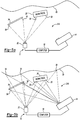
- a laser projection system for projecting an image on a workpiece is generally shown at 10 of Figure 1 .
- the laser projection system includes a photogrammetry assembly 12 and a laser projector 14, each of which communicates via a computer 16.
- the computer 16 communicates with the laser projector 14 by way of electrical circuit 18 and with the photogrammetry assembly 12 by way of electrical circuit 20.
- the electrical circuits 18, 20 are represented as hard wires in this embodiment, it should be understood by those of skill in the art that radio frequency or equivalent transmission between the computer 16, the photogrammetry assembly 12 and the laser projector 14 is within the scope of this invention.
- the photogrammetry assembly includes a first camera, 22 and, a second camera 24.
- One type of camera contemplated by the inventors is an industrial camera model acA2500-14GM manufactured by Basler AG. However, other industrial type cameras having equivalent functionality is suitable for use with the inventive projection system 10.
- the photogrammetry assembly 12 is adapted to scan and take an image of a workpiece 26 and a surrounding environment 28 for the purpose of locating the workpiece 26 in a three-dimensional coordinate system.
- the laser projector 14 projects a laser image to arbitrary locations 30 with at least some of the laser image being projected onto the workpiece 26.
- the laser image takes the form of a plurality of laser beams, laser patterns, or manufacturing template, or combinations thereof.
- the laser image generated by the laser projector 14 is readable by the photogrammetry assembly 12. More specifically, the laser image is readable by the first and second camera 22, 24.
- the first and second cameras 22, 24 are separated a known distance by a spacer bar 32 manufactured from the material not subject to dimensional variations due to temperature fluctuations.
- the spacer bar 32 is manufactured from a unidirectional carbon fiber to provide temperature resistance to dimensional variation.
- the first and second cameras 22, 24 identify the arbitrary locations 30 onto which the laser image is projected by the laser projector 14 by triangulating the image and signaling the computer 16 to calculate where the arbitrary locations 30 are located in a three-dimensional coordinate system.
- the computer 16 is programmed to calculate the geometric correlation between the photogrammetry assembly 12, the laser projector 14 and the workpiece 26 by way of a signal transmitted from the cameras 22, 24 of the scanned arbitrary locations 30 onto which the laser image is projected. Additional accuracy is achievable by manipulating the laser projector 14 to project a laser image onto the various features such as, for example, corners or apertures defined by the workpiece 26 and scanning the laser image as set forth above.
- the computer 16 establishes a geometric correlation between the photogrammetry assembly 12 the laser projector 14 and the workpiece 26, the laser image is corrected to a geometric location relative to the workpiece 26 and is used as a template for an assembly aid to perform work on the workpiece 26.
- the laser template identifies the location of a weld operation, a machine operation, or other work intended to be performed on the workpiece 26.
- the computer 16 periodically prompts the projector 14 to project a laser image to arbitrary locations 30 from which the photogrammetry assembly 12 scans and signals the computer 16 to calculate the geometric correlation between the photogrammetry assembly 12, the laser projector 14, and the workpiece 26 to verify none of these items have been moved, there has been no drift of the image, and that the laser template is projected in the correct geometric location on the workpiece 26. In this manner, the accuracy of the laser projection of the template is repeatedly updated during the manufacturing operation.
- the photogrammetry assembly 12 includes a light source 34 ( Figure 4 ) transmitting light that is readable by the photogrammetry assembly 12 separate from the laser image.
- the light source 34 transmits light in a similar wave-length range as that of the laser projector 14. More specifically, it is contemplated that green light having a wave length range between 540 and 520 nanometers is transmitted by both the light source 34 and the laser projector 14.
- the light source 34 includes a plurality of light emitting diode spaced around each camera lens 36 of the first and second cameras 22, 24 as best represented in Figure 4 .
- the light source 34 can be separate from the photogrammetry assembly 12 as will be explained further below.
- the light source 34 transmit light toward the workpiece 26 onto which reflective targets 38 are temporarily affixed.
- the reflective targets 38 are contemplated to be retroreflective targets for reflecting light back toward the photogrammetry assembly 12 into the camera lens 36 of the first and second cameras 22, 24 so that the photogrammetry assembly 12 signal the computer 16 the location of the reflective targets 38 allowing the computer 16 to calculate the precise location of the workpiece 26 in a geometric coordinate system.
- the inventor contemplates the reflective targets 38 be encoded to enable a computer to identify which reflective targets 38 are signaling the photogrammetry assembly 12.
- one method of encoding the reflective targets 38 is by way of two reflective elements disposed upon individual reflective targets 38 and spaced a known distance enabling the computer 6 to read two reflective images spaced a known distance from an individual reflective target 38. It is also believed that encoding the reflective targets 38 reduces the probability of the photogrammetry assembly 12 reading reflections from the environment 28 in error rendering an incorrect calculation of the location of the workpiece 26 in the coordinate system.
- the light source 34 periodically emits light contemplated to be in the form of a flash so that the computer 16 can continuously calculate the location of the workpiece 26 within the geometric coordinate system.
- the laser projector 14 projects a laser image to arbitrary locations as set forth in the previous embodiment. Therefore, the photogrammetry assembly 12 scans both light reflected from the reflective targets 38 and the laser image projected on arbitrary locations 30 by the laser projector 14 to accurately determine spatial relationship within a geometric coordinate system of the photogrammetry assembly 12, the laser projector 14, and the workpiece 26. It should be understood by those of skill in the art that the light source 34 can also transmit light from the location of the reflective targets 38 are affixed.
- light emitting diodes 34 would replace the reflective targets 38 and transmit light directly to the photogrammetry assembly 12. It should be understood that when the term reflect or reflector is used transmitting light as described above is also included so that light is conveyed from the direction of the workpiece.
- the probe 40 includes a contact element 42 disposed upon a distal end 44 of a shaft 46.
- the reflective target 48 is disposed on an opposite end of the shaft 46 from a contact element 42.
- the reflective target 48 is contemplated to include a plurality of arms 50 each having encoded reflectors 52.
- the use of four reflectors 52 has proven to improve the accuracy of the measurements of the geometrically relevant features on the workpiece, particularly when the reflectors 52 are spaced from an axis of the probe defined by the contact element 42.
- the reflectors 52 are encoded by locating a plurality of reflectors 52 on each arm 50 spaced by a known distance.
- encoding may also be used such as, for example, altering the reflectivity of an individual reflector 52.
- the photogrammetry assembly 12 is able to determine which specific probe 48 is reflecting light from the light source 34 to the photogrammetry assembly 12. Encoding is desirable when a plurality of probes 40 are used to identify various features on the workpiece 26 as will be explained further below.
- the probe 40 is shown reflecting light received from the light source 34 to the first and second camera 22, 24, allowing the computer 16 to determine the location of the probe 40 in the geometric coordinate system in which the workpiece 26 exists.
- the contact element 42 of the probe 40 is manually touched to a particular feature on the workpiece 26. This approach streamlines the determination of the important features or datums on the workpiece necessary for performing work on the workpiece in a dimensionally accurate manner, and reduces the time required to project the laser template onto the workpiece. For example, the contact element 42 is touched to an edge of an aperture (not shown) that is a datum from which a work location must be accurately correlated.
- the laser projector 14 transmits a laser image in the form of a template further increasing the accuracy of the location of the laser image on the workpiece 26.
- the contact element 42 is touched to various edges or contours of a specific element to further define the location of the element by way of the probe 40 again enhancing the accuracy of the template projected on the workpiece 26 by the laser projector 14.
- the contact element 42 includes different shapes and sizes mirroring the various features of the workpiece 26 requiring location identification inside the coordinate system.
- FIG. 5a and 5b An alternative example of a projection system is generally shown at 210 of Figure 5a and 5b .
- the photogrammetry assembly 12 makes use of a single camera 22 and communicates with the laser projector 14 and the computer 16 as explained above. Because a single camera 22 is used to scan the workpiece 26, it is desirable to establish a geometric scale of the relative position of the workpiece 26. As such, a scale bar 54 having scale reflective targets 56 spaced a known distance on a scale bar 54. Through triangulation with the spaced scale reflective targets 56 and the camera 22, the computer 16 is able to establish a geometric scale of the workpiece 26 in a geometric coordinate system. As set forth above, the workpiece surface is identified by temporarily affixing reflective targets 38 which are encoded.
- the light source 34 transmits light to the reflective targets 38 and to the scale reflective targets 56 and the photogrammetry assembly scans the reflective image to signal the computer 16 the coordinates of the workpiece 26, allowing the computer 16 to correlate the photogrammetry assembly 12, the laser projector 14, and the workpiece 26 in a geometric coordinate system. This allows the laser projector 14 to project a laser template upon the workpiece 26 as set forth above. It should be understood to those of skill in the art that the probe 40 may also be used in combination with the scale bar 54 and scale reflective targets 56 to accurately determine precise location of various features of the workpiece 26.
Landscapes
- Engineering & Computer Science (AREA)
- Physics & Mathematics (AREA)
- General Physics & Mathematics (AREA)
- Multimedia (AREA)
- Computer Vision & Pattern Recognition (AREA)
- Remote Sensing (AREA)
- Radar, Positioning & Navigation (AREA)
- Signal Processing (AREA)
- Theoretical Computer Science (AREA)
- Optics & Photonics (AREA)
- Quality & Reliability (AREA)
- Electromagnetism (AREA)
- Mechanical Engineering (AREA)
- Length Measuring Devices By Optical Means (AREA)
- Laser Beam Processing (AREA)
Claims (13)
- Ein Laserprojektionssystem (10, 110, 210) zum Projizieren einer Schablone auf ein Werkstück (26), aufweisend:eine Photogrammetrie-Anordnung (12) und einen Laserprojektor (14), die jeweils konfiguriert sind, um mit einem Computer (16) zu kommunizieren; wobei die Photogrammetrie-Anordnung (12) eine erste Kamera (22) und eine zweite Kamera (24), die von der ersten Kamera (22) beabstandet ist, beinhaltet, um das Werkstück (26) abzutasten, und wobeider Laserprojektor (14) konfiguriert ist, ein Laserbild auf beliebige Orte (30) und auf das Werkstück (26) zu projizieren, wobei das Laserbild von den Kameras (22, 24) lesbar ist;wobei die Photogrammetrie-Anordnung (12) konfiguriert ist, Licht abzutasten, das aus der Richtung der beliebigen Orte (30), auf die das Laserbild projiziert wird, übermittelt wird, Licht abzutasten, das aus der Richtung des Werkstücks (26) übermittelt wird, und ein Signal bezüglich der abgetasteten beliebigen Orte (30) und des abgetasteten Werkstücks (26) an den Computer (16) zu übertragen;wobei der Computer (16) programmiert ist, zum Berechnen einer geometrischen Korrelation zwischen der Photogrammetrie-Anordnung (12), dem Laserprojektor (14), und dem Werkstück (26) basierend auf dem Signal von den Kameras (22, 24) bezüglich der abgetasteten beliebigen Orte (30) und des abgetasteten Werkstücks (26), um zu verifizieren, dass keines dieser Elemente bewegt worden ist; undzum Signalisieren an den Laserprojektor (14), eine Schablone auf einen gewünschten Ort des Werkstücks (26) zu projizieren basierend auf der berechneten geometrischen Korrelation.
- Das System (10, 110, 210) nach Anspruch 1, wobei die Photogrammetrie-Anordnung (12) eine Lichtquelle (34) zum Übertragen von Licht beinhaltet, das von der Photogrammetrie-Anordnung (12) lesbar ist und sich von dem Laserbild unterscheidet.
- Das System (10, 110, 210) nach Anspruch 2, weiter beinhaltend einen Maßstabsbalken (54) mit reflektierenden Zielen (56), die um einen bekannten Abstand beabstandet sind, zum Reflektieren des von der Lichtquelle (34) übertragenen Lichts zu der ersten Kamera (22).
- Das System (10, 110, 210) nach einem der Ansprüche 2 oder 3, weiter beinhaltend retroreflektierende Ziele (38), die an dem Werkstück (26) befestigt sind, zum Reflektieren von Licht von der Lichtquelle (34), dadurch das Licht zu der ersten Kamera (22) übermittelnd, wobei die erste Kamera (22) dem Computer (16) einen Ort der retroreflektierenden Ziele (38) signalisiert und der Computer (16) einen Ort des Werkstücks (26) bestimmt.
- Das System (10, 110, 210) nach einem der Ansprüche 2 bis 4, weiter beinhaltend einen Prüfkopf (40) mit darauf angeordneten reflektierenden Zielen (48) zum manuellen Identifizieren von Merkmalen des Werkstücks (26) mit Licht, das von der Lichtquelle (34) übertragen wird und übermittelt wird von den reflektierenden Zielen (48) zu der Photogrammetrie-Anordnung (12).
- Das System nach einem der Ansprüche 1 bis 5, wobei die von dem Laserprojektor (14) projizierte Schablone eine Fertigungsschablone ist, die einen Ort zum Durchführen von Arbeit an dem Werkstück (26) bereitstellt.
- Ein Verfahren zum Projizieren einer Schablone auf ein Werkstück (26), aufweisend die folgenden Schritte:Bereitstellen einer Photogrammetrie-Anordnung (12) und eines Laserprojektors (14), die jeweils konfiguriert sind, um mit einem Computer (16) zu kommunizieren, wobei die Photogrammetrie-Anordnung (12) eine erste Kamera (22) und eine von der ersten Kamera (22) getrennte zweite Kamera (24) zum Abtasten des Werkstücks (26) enthält;Projizieren eines Laserbildes an beliebige Orte (30) und auf das Werkstück (26) durch den Laserprojektor (14), wobei das Laserbild durch die Kameras (22, 24) lesbar ist;Abtasten, durch die Photogrammetrie-Anordnung (12), von Licht, das aus der Richtung der beliebigen Orte (30), auf die das Laserbild projiziert wird, übermittelt wird, Abtasten, durch die Photogrammetrie-Anordnung (12), von Licht, das aus der Richtung des Werkstücks (26) übermittelt wird, und Übertragen, durch die Photogrammetrie-Anordnung (12), eines Signals bezüglich der abgetasteten beliebigen Orte (30) und des abgetasteten Werkstücks (26), an den Computer (16);Berechnen, durch den Computer (16), einer geometrischen Korrelation zwischen der Photogrammetrie-Anordnung (12), dem Laserprojektor (14), und dem Werkstück (26) basierend auf dem Signal von den Kameras (22, 24) bezüglich der abgetasteten beliebigen Orte (30) und des abgetasteten Werkstücks (26), um zu verifizieren, dass keines dieser Elemente bewegt worden ist; undProjizieren einer Schablone auf einen gewünschten Ort des Werkstücks (26) von dem Laserprojektor (14) basierend auf der berechneten geometrischen Korrelation.
- Das Verfahren nach Anspruch 7, wobei der Schritt des Abtastens von Licht aus der Richtung des Werkstücks (26) weiter definiert ist durch Abtasten von reflektierendem Licht von mindestens einer Lichtquelle (34) oder einem Muster, das von dem Laserprojektor (14) erzeugt wird, auf die Photogrammetrie-Anordnung (12).
- Das Verfahren nach einem der Ansprüche 7 oder 8, weiter beinhaltend den Schritt von Abtasten, durch die Photogrammetrie-Anordnung (12), eines das Werkstück (26) aufweisenden Raums, um ein Hintergrundbild zu erstellen, und von Subtrahieren des Hintergrundbilds von dem Licht, das aus der Richtung des Werkstücks (26) übermittelt wird.
- Das Verfahren nach einem der Ansprüche 7 bis 9, weiter beinhaltend den Schritt von Übertragen von Licht von einer Lichtquelle (34) auf reflektierende Ziele (38), die an dem Werkstück (26) angeordnet sind, um Licht in Richtung der Photogrammetrie-Anordnung (12) zu übermitteln, und von Bestimmen einer räumlichen Beziehung des Werkstücks (26) zu der Photogrammetrie-Anordnung (12).
- Das Verfahren nach einem der Ansprüche 7 bis 10, wobei der Schritt des Abtastens von Licht aus der Richtung des Werkstücks (26) weiter definiert ist durch Verorten von Merkmalen auf dem Werkstück (26) durch Kontaktieren der Merkmale mit einem reflektierenden Prüfkopf (38) und Reflektieren von Licht in Richtung der Photogrammetrie-Anordnung (12) zum Bestimmen eines geometrischen Ortes der Merkmale.
- Das Verfahren nach einem der Ansprüche 7 bis 11, weiter beinhaltend den Schritt des Bestimmens einer räumlichen Beziehung des Werkstücks (26) zu der Photogrammetrie-Anordnung (12) durch Abtasten von Licht, das zu der Photogrammetrie-Anordnung (12) zurückreflektiert wird.
- Das Verfahren nach einem der Ansprüche 7, 11 und 12, weiter beinhaltend den Schritt des Befestigens von reflektierenden Zielen (38) an dem Werkstück (26), um von einer Lichtquelle (34) erzeugtes Licht zu der Photogrammetrie-Anordnung (12) zu übermitteln, um einen Ort des Werkstücks (26) in dem dreidimensionalen Koordinatensystem zu bestimmen.
Applications Claiming Priority (2)
| Application Number | Priority Date | Filing Date | Title |
|---|---|---|---|
| US201261614252P | 2012-03-22 | 2012-03-22 | |
| US13/652,735 US9200899B2 (en) | 2012-03-22 | 2012-10-16 | Laser projection system and method |
Publications (3)
| Publication Number | Publication Date |
|---|---|
| EP2642246A2 EP2642246A2 (de) | 2013-09-25 |
| EP2642246A3 EP2642246A3 (de) | 2017-04-12 |
| EP2642246B1 true EP2642246B1 (de) | 2021-05-26 |
Family
ID=47628050
Family Applications (1)
| Application Number | Title | Priority Date | Filing Date |
|---|---|---|---|
| EP13153808.4A Active EP2642246B1 (de) | 2012-03-22 | 2013-02-04 | Laserprojektionssystem und -verfahren |
Country Status (3)
| Country | Link |
|---|---|
| US (3) | US9200899B2 (de) |
| EP (1) | EP2642246B1 (de) |
| CN (1) | CN103322943B (de) |
Families Citing this family (52)
| Publication number | Priority date | Publication date | Assignee | Title |
|---|---|---|---|---|
| US10464172B2 (en) | 2013-02-21 | 2019-11-05 | Nlight, Inc. | Patterning conductive films using variable focal plane to control feature size |
| WO2014130895A1 (en) | 2013-02-21 | 2014-08-28 | Nlight Photonics Corporation | Laser patterning multi-layer structures |
| US9491448B2 (en) * | 2013-04-01 | 2016-11-08 | The Boeing Company | Laser videogrammetry |
| US20150022635A1 (en) * | 2013-07-19 | 2015-01-22 | Blackberry Limited | Using multiple flashes when obtaining a biometric image |
| DE102013114707A1 (de) | 2013-12-20 | 2015-06-25 | EXTEND3D GmbH | Verfahren zur Durchführung und Kontrolle eines Bearbeitungsschritts an einem Werkstück |
| JP6376809B2 (ja) * | 2014-04-03 | 2018-08-22 | キヤノン株式会社 | 三次元形状計測システムに用いられる投影装置および撮像装置 |
| US10069271B2 (en) | 2014-06-02 | 2018-09-04 | Nlight, Inc. | Scalable high power fiber laser |
| US10618131B2 (en) | 2014-06-05 | 2020-04-14 | Nlight, Inc. | Laser patterning skew correction |
| US10310201B2 (en) | 2014-08-01 | 2019-06-04 | Nlight, Inc. | Back-reflection protection and monitoring in fiber and fiber-delivered lasers |
| EP2980528A1 (de) * | 2014-08-01 | 2016-02-03 | HILTI Aktiengesellschaft | Trackingverfahren und Trackingsystem |
| CN104182095B (zh) * | 2014-08-13 | 2017-06-30 | 长春理工大学 | 移动式自定位激光3d投影系统 |
| WO2016046788A1 (en) * | 2014-09-24 | 2016-03-31 | Bombardier Inc. | Laser vision inspection system and method |
| RS57736B1 (sr) * | 2014-12-12 | 2018-12-31 | Turanjanin Uros | Primena 3d kamera u procesu savijanja profila na mašini za savijanje sa tri i četiri valjka |
| US9837783B2 (en) | 2015-01-26 | 2017-12-05 | Nlight, Inc. | High-power, single-mode fiber sources |
| DE102016203377A1 (de) | 2015-03-02 | 2016-11-24 | Virtek Vision International Inc. | Laserprojektionssystem mit Videoüberlagerung |
| US10050404B2 (en) | 2015-03-26 | 2018-08-14 | Nlight, Inc. | Fiber source with cascaded gain stages and/or multimode delivery fiber with low splice loss |
| US10210607B1 (en) | 2015-04-08 | 2019-02-19 | Wein Holding LLC | Digital projection system and method for workpiece assembly |
| CN107924023B (zh) | 2015-07-08 | 2020-12-01 | 恩耐公司 | 具有用于增加的光束参数乘积的中心折射率受抑制的纤维 |
| US10594993B2 (en) * | 2015-09-23 | 2020-03-17 | Hewlett-Packard Development Company, L.P. | Image projections |
| US11179807B2 (en) | 2015-11-23 | 2021-11-23 | Nlight, Inc. | Fine-scale temporal control for laser material processing |
| CN108367389B (zh) | 2015-11-23 | 2020-07-28 | 恩耐公司 | 激光加工方法和装置 |
| CN108698164B (zh) | 2016-01-19 | 2021-01-29 | 恩耐公司 | 处理3d激光扫描仪系统中的校准数据的方法 |
| US10730785B2 (en) | 2016-09-29 | 2020-08-04 | Nlight, Inc. | Optical fiber bending mechanisms |
| WO2018063452A1 (en) | 2016-09-29 | 2018-04-05 | Nlight, Inc. | Adjustable beam characteristics |
| US10732439B2 (en) | 2016-09-29 | 2020-08-04 | Nlight, Inc. | Fiber-coupled device for varying beam characteristics |
| US10239178B2 (en) | 2016-10-17 | 2019-03-26 | Virtek Vision International, ULC | Laser projector with dynamically adaptable focus |
| KR102611837B1 (ko) * | 2017-04-04 | 2023-12-07 | 엔라이트 인크. | 검류계 스캐너 보정을 위한 광학 기준 생성 |
| CN107202554B (zh) * | 2017-07-06 | 2018-07-06 | 杭州思看科技有限公司 | 同时具备摄影测量和三维扫描功能的手持式大尺度三维测量扫描仪系统 |
| CN109323691B (zh) * | 2017-07-31 | 2022-08-09 | 华为技术有限公司 | 一种定位系统以及定位方法 |
| US20190052851A1 (en) | 2017-08-11 | 2019-02-14 | Hilti Aktiengesellschaft | System and Method for Recalibrating a Projector System |
| CN107861311A (zh) * | 2017-10-10 | 2018-03-30 | 神画科技(深圳)有限公司 | 一种带监控装置的投影系统 |
| DE102019204843A1 (de) * | 2018-04-06 | 2019-10-10 | Virtek Vision International Ulc | Erkennen von Fluoreszenz von Fremdmaterial |
| DE102019204933A1 (de) | 2018-04-10 | 2019-10-10 | Virtek Vision International Ulc | Gerichtete energie und abtastung zur erkennung von inkonsistenzen in laminaten |
| WO2019206454A1 (de) | 2018-04-26 | 2019-10-31 | Linde Aktiengesellschaft | Verfahren zur darstellung einer positionierlinie im raum |
| US11402627B2 (en) * | 2018-11-19 | 2022-08-02 | Virtek Vision International Inc. | System and method for limiting laser exposure of arbitrary laser template projection |
| US11295461B2 (en) * | 2019-01-16 | 2022-04-05 | Virtek Vision International Ulc | Precision registration of images for assembly validation |
| DE102020201884B4 (de) | 2019-02-15 | 2021-12-23 | Virtek Vision International Ulc | Verfahren von detektieren richtiger orientierung von materialapplikation |
| US11345014B2 (en) * | 2019-02-15 | 2022-05-31 | Virtek Vision International Inc | Method of detecting proper orientation of material applique |
| US11988889B2 (en) | 2019-11-15 | 2024-05-21 | Faro Technologies, Inc. | Laser projector system |
| GB2594505A (en) | 2020-04-30 | 2021-11-03 | Airbus Operations Ltd | Photogrammetry target system |
| US11656072B2 (en) * | 2020-07-02 | 2023-05-23 | Virtek Vision International Inc. | Classification of laser speckle profiles for validation of part placement in an assembly task |
| US11828711B2 (en) | 2020-10-09 | 2023-11-28 | Virtek Vision International Inc | Method and system for inspecting repair or assembly operations |
| US12025442B2 (en) | 2020-10-09 | 2024-07-02 | Virtek Vision International Inc. | Control of an optical indicator system through manipulation of physical objects |
| JP7563963B2 (ja) * | 2020-12-10 | 2024-10-08 | 株式会社Subaru | 画像投影型測定装置 |
| US12028504B2 (en) | 2021-02-20 | 2024-07-02 | Virtek Vision International, Inc. | Projection system for directing and monitoring activity in large scale facilities |
| US11828596B2 (en) | 2021-05-03 | 2023-11-28 | Virtek Vision International Inc | Optical template projection using positional reference |
| DE102022204320A1 (de) | 2021-05-03 | 2022-11-03 | Virtek Vision International, Inc. | Optische schablonenprojektion unter verwendung von positionsreferenz |
| CN114089369A (zh) * | 2021-10-28 | 2022-02-25 | 北京天科微测科技有限公司 | 三维激光定位投影装置 |
| DE102023201313A1 (de) | 2022-02-18 | 2023-08-24 | Virtek Vision International Inc. | Steuerung eines optischen anzeigesystems durch manipulation von physikalischen objekten |
| CN114814866A (zh) * | 2022-02-25 | 2022-07-29 | 中煤科工开采研究院有限公司 | 测距装置及方法 |
| US12322085B2 (en) | 2022-04-14 | 2025-06-03 | Virtek Vision International Inc. | Method and system for inspecting a surface with artificial intelligence assist |
| US12320759B2 (en) | 2022-04-14 | 2025-06-03 | Virtek Vision International Inc. | Method and system for inspecting a surface with artifical intelligence assist |
Citations (1)
| Publication number | Priority date | Publication date | Assignee | Title |
|---|---|---|---|---|
| US6547397B1 (en) * | 2000-04-19 | 2003-04-15 | Laser Projection Technologies, Inc. | Apparatus and method for projecting a 3D image |
Family Cites Families (22)
| Publication number | Priority date | Publication date | Assignee | Title |
|---|---|---|---|---|
| US4791482A (en) | 1987-02-06 | 1988-12-13 | Westinghouse Electric Corp. | Object locating system |
| DE4207632C2 (de) | 1992-03-11 | 1995-07-20 | Bodenseewerk Geraetetech | Vorrichtung und Verfahren zur Positionierung eines Körperteils für Behandlungszwecke |
| US5603318A (en) | 1992-04-21 | 1997-02-18 | University Of Utah Research Foundation | Apparatus and method for photogrammetric surgical localization |
| US5388318A (en) | 1992-10-09 | 1995-02-14 | Laharco, Inc. | Method for defining a template for assembling a structure |
| US5663795A (en) * | 1995-09-07 | 1997-09-02 | Virtek Vision Corp. | Method of calibrating laser positions relative to workpieces |
| US20020036617A1 (en) * | 1998-08-21 | 2002-03-28 | Timothy R. Pryor | Novel man machine interfaces and applications |
| ATE292784T1 (de) * | 1999-04-30 | 2005-04-15 | Christoph Dr Wagner | Verfahren zur optischen formerfassung von gegenständen |
| CA2537873A1 (en) * | 2003-09-08 | 2005-03-24 | Laser Projection Technologies, Inc. | 3d projection with image recording |
| US7463368B2 (en) * | 2003-09-10 | 2008-12-09 | Metris Canada Inc | Laser projection system, intelligent data correction system and method |
| US20060038188A1 (en) * | 2004-08-20 | 2006-02-23 | Erchak Alexei A | Light emitting diode systems |
| US8085388B2 (en) * | 2005-02-01 | 2011-12-27 | Laser Projection Technologies, Inc. | Laser radar projection with object feature detection and ranging |
| JP4644540B2 (ja) | 2005-06-28 | 2011-03-02 | 富士通株式会社 | 撮像装置 |
| US8525077B2 (en) * | 2006-05-09 | 2013-09-03 | Lincoln Global, Inc. | Touch screen waveform design apparatus for welders |
| US7876457B2 (en) * | 2007-06-13 | 2011-01-25 | Nikon Metrology Nv | Laser metrology system and method |
| US8757812B2 (en) * | 2008-05-19 | 2014-06-24 | University of Washington UW TechTransfer—Invention Licensing | Scanning laser projection display devices and methods for projecting one or more images onto a surface with a light-scanning optical fiber |
| US8462207B2 (en) | 2009-02-12 | 2013-06-11 | Primesense Ltd. | Depth ranging with Moiré patterns |
| JP4715944B2 (ja) * | 2009-04-03 | 2011-07-06 | オムロン株式会社 | 三次元形状計測装置、三次元形状計測方法、および三次元形状計測プログラム |
| US9151607B2 (en) | 2010-05-31 | 2015-10-06 | University Of North Carolina At Charlotte | Dimensional measurement through a combination of photogrammetry and optical scattering |
| CN103003713B (zh) * | 2010-09-08 | 2015-04-01 | 法罗技术股份有限公司 | 具有投影器的激光扫描器或激光跟踪器 |
| US20120226152A1 (en) * | 2011-03-03 | 2012-09-06 | Porikli Fatih M | Tumor Tracking System and Method for Radiotherapy |
| US8358333B2 (en) * | 2011-03-04 | 2013-01-22 | The Boeing Company | Photogrammetry measurement system |
| CN102288131A (zh) * | 2011-05-12 | 2011-12-21 | 上海大学 | 物体360°轮廓误差的自适应条纹测量装置和方法 |
-
2012
- 2012-10-16 US US13/652,735 patent/US9200899B2/en active Active
-
2013
- 2013-02-04 EP EP13153808.4A patent/EP2642246B1/de active Active
- 2013-03-22 CN CN201310092944.1A patent/CN103322943B/zh active Active
-
2015
- 2015-11-30 US US14/954,117 patent/US20160091311A1/en not_active Abandoned
-
2017
- 2017-02-14 US US15/432,331 patent/US10157458B2/en active Active
Patent Citations (1)
| Publication number | Priority date | Publication date | Assignee | Title |
|---|---|---|---|---|
| US6547397B1 (en) * | 2000-04-19 | 2003-04-15 | Laser Projection Technologies, Inc. | Apparatus and method for projecting a 3D image |
Also Published As
| Publication number | Publication date |
|---|---|
| US10157458B2 (en) | 2018-12-18 |
| EP2642246A2 (de) | 2013-09-25 |
| EP2642246A3 (de) | 2017-04-12 |
| CN103322943A (zh) | 2013-09-25 |
| US9200899B2 (en) | 2015-12-01 |
| US20130250094A1 (en) | 2013-09-26 |
| US20160091311A1 (en) | 2016-03-31 |
| US20170161889A1 (en) | 2017-06-08 |
| CN103322943B (zh) | 2018-11-20 |
Similar Documents
| Publication | Publication Date | Title |
|---|---|---|
| EP2642246B1 (de) | Laserprojektionssystem und -verfahren | |
| US12358145B2 (en) | System and method for three-dimensional calibration of a vision system | |
| US9815204B2 (en) | Apparatus and method to optically locate workpiece for robotic operations | |
| US10799998B2 (en) | Laser projector with flash alignment | |
| US9656390B2 (en) | Human-centric robot with noncontact measurement device | |
| JP6366405B2 (ja) | レーザレーダ装置 | |
| KR20150001619A (ko) | 정확한 구조물 마킹 및 마킹-보조 구조물을 위치시키기 위한 장치 및 방법 | |
| KR20210019014A (ko) | 공간의 복잡한 표면에서 지점의 위치를 결정하기 위한 방법 및 플랜트 | |
| CN102435138B (zh) | 确定机动车辆的车身件的间隙和/或齐平性的方法以及测量装置 | |
| US11276198B2 (en) | Apparatus for determining dimensional and geometric properties of a measurement object | |
| JP2017019072A (ja) | 位置計測システム | |
| US20200132450A1 (en) | Coordinate measuring system | |
| CN108267133B (zh) | 一种激光式反射板坐标系冗余标定方法及激光导航系统 | |
| CN114527471A (zh) | 一种非接触式铺层定位仪定位方法 | |
| KR101782317B1 (ko) | 3차원 스캐너를 이용한 로봇 캘리브레이션 장치 및 이를 이용한 로봇 캘리브레이션 방법 | |
| CN108229020B (zh) | 一种智能投影系统的投影控制方法及系统 | |
| US20170309035A1 (en) | Measurement apparatus, measurement method, and article manufacturing method and system | |
| JP6165069B2 (ja) | 罫書き作業支援システム、罫書き作業方法及び機械加工部品 | |
| JP2018044863A (ja) | 計測装置、計測方法、システム及び物品の製造方法 | |
| KR20170136054A (ko) | 물체의 3차원 형상을 센싱하기 위한 센서 테스트 베드, 물체 센싱 장치 및 물체 센싱 방법 | |
| JP2014149303A (ja) | 三次元形状計測装置、キャリブレーションブロック、三次元形状計測装置のキャリブレーション方法 | |
| US11948321B2 (en) | Three-dimensional geometry measurement apparatus and three-dimensional geometry measurement method | |
| KR102771537B1 (ko) | 이종 광학센서 캘리브레이션 방법 및 이를 이용한 모니터링 시스템 | |
| EP3966654B1 (de) | Positionierung von autonomen fahrzeugen | |
| JP2009008533A (ja) | 光学式測定システム |
Legal Events
| Date | Code | Title | Description |
|---|---|---|---|
| PUAI | Public reference made under article 153(3) epc to a published international application that has entered the european phase |
Free format text: ORIGINAL CODE: 0009012 |
|
| AK | Designated contracting states |
Kind code of ref document: A2 Designated state(s): AL AT BE BG CH CY CZ DE DK EE ES FI FR GB GR HR HU IE IS IT LI LT LU LV MC MK MT NL NO PL PT RO RS SE SI SK SM TR |
|
| AX | Request for extension of the european patent |
Extension state: BA ME |
|
| RIC1 | Information provided on ipc code assigned before grant |
Ipc: G01C 11/02 20060101ALI20161017BHEP Ipc: G01C 15/00 20060101AFI20161017BHEP Ipc: G06T 7/00 20060101ALI20161017BHEP Ipc: G01B 11/00 20060101ALI20161017BHEP Ipc: G01B 11/25 20060101ALI20161017BHEP |
|
| PUAL | Search report despatched |
Free format text: ORIGINAL CODE: 0009013 |
|
| AK | Designated contracting states |
Kind code of ref document: A3 Designated state(s): AL AT BE BG CH CY CZ DE DK EE ES FI FR GB GR HR HU IE IS IT LI LT LU LV MC MK MT NL NO PL PT RO RS SE SI SK SM TR |
|
| AX | Request for extension of the european patent |
Extension state: BA ME |
|
| RIC1 | Information provided on ipc code assigned before grant |
Ipc: G06T 7/00 20170101ALI20170308BHEP Ipc: G01C 11/02 20060101ALI20170308BHEP Ipc: G01B 11/00 20060101ALI20170308BHEP Ipc: G01C 15/00 20060101AFI20170308BHEP Ipc: G01B 11/25 20060101ALI20170308BHEP |
|
| STAA | Information on the status of an ep patent application or granted ep patent |
Free format text: STATUS: REQUEST FOR EXAMINATION WAS MADE |
|
| 17P | Request for examination filed |
Effective date: 20171012 |
|
| RBV | Designated contracting states (corrected) |
Designated state(s): AL AT BE BG CH CY CZ DE DK EE ES FI FR GB GR HR HU IE IS IT LI LT LU LV MC MK MT NL NO PL PT RO RS SE SI SK SM TR |
|
| RAP1 | Party data changed (applicant data changed or rights of an application transferred) |
Owner name: VIRTEK VISION INTERNATIONAL ULC |
|
| STAA | Information on the status of an ep patent application or granted ep patent |
Free format text: STATUS: EXAMINATION IS IN PROGRESS |
|
| 17Q | First examination report despatched |
Effective date: 20181017 |
|
| REG | Reference to a national code |
Ref country code: DE Ref legal event code: R079 Ref document number: 602013077626 Country of ref document: DE Free format text: PREVIOUS MAIN CLASS: G01C0011000000 Ipc: G01C0015000000 |
|
| RIC1 | Information provided on ipc code assigned before grant |
Ipc: G06T 7/00 20170101ALI20201105BHEP Ipc: G01B 11/00 20060101ALI20201105BHEP Ipc: G01B 11/25 20060101ALI20201105BHEP Ipc: G01C 11/02 20060101ALI20201105BHEP Ipc: G01C 15/00 20060101AFI20201105BHEP |
|
| GRAP | Despatch of communication of intention to grant a patent |
Free format text: ORIGINAL CODE: EPIDOSNIGR1 |
|
| STAA | Information on the status of an ep patent application or granted ep patent |
Free format text: STATUS: GRANT OF PATENT IS INTENDED |
|
| INTG | Intention to grant announced |
Effective date: 20201218 |
|
| RIN1 | Information on inventor provided before grant (corrected) |
Inventor name: RUEB, KURT D. |
|
| GRAS | Grant fee paid |
Free format text: ORIGINAL CODE: EPIDOSNIGR3 |
|
| GRAA | (expected) grant |
Free format text: ORIGINAL CODE: 0009210 |
|
| STAA | Information on the status of an ep patent application or granted ep patent |
Free format text: STATUS: THE PATENT HAS BEEN GRANTED |
|
| AK | Designated contracting states |
Kind code of ref document: B1 Designated state(s): AL AT BE BG CH CY CZ DE DK EE ES FI FR GB GR HR HU IE IS IT LI LT LU LV MC MK MT NL NO PL PT RO RS SE SI SK SM TR |
|
| REG | Reference to a national code |
Ref country code: GB Ref legal event code: FG4D |
|
| REG | Reference to a national code |
Ref country code: CH Ref legal event code: EP |
|
| REG | Reference to a national code |
Ref country code: AT Ref legal event code: REF Ref document number: 1396665 Country of ref document: AT Kind code of ref document: T Effective date: 20210615 |
|
| REG | Reference to a national code |
Ref country code: DE Ref legal event code: R096 Ref document number: 602013077626 Country of ref document: DE |
|
| REG | Reference to a national code |
Ref country code: IE Ref legal event code: FG4D |
|
| REG | Reference to a national code |
Ref country code: LT Ref legal event code: MG9D |
|
| REG | Reference to a national code |
Ref country code: AT Ref legal event code: MK05 Ref document number: 1396665 Country of ref document: AT Kind code of ref document: T Effective date: 20210526 |
|
| PG25 | Lapsed in a contracting state [announced via postgrant information from national office to epo] |
Ref country code: FI Free format text: LAPSE BECAUSE OF FAILURE TO SUBMIT A TRANSLATION OF THE DESCRIPTION OR TO PAY THE FEE WITHIN THE PRESCRIBED TIME-LIMIT Effective date: 20210526 Ref country code: LT Free format text: LAPSE BECAUSE OF FAILURE TO SUBMIT A TRANSLATION OF THE DESCRIPTION OR TO PAY THE FEE WITHIN THE PRESCRIBED TIME-LIMIT Effective date: 20210526 Ref country code: BG Free format text: LAPSE BECAUSE OF FAILURE TO SUBMIT A TRANSLATION OF THE DESCRIPTION OR TO PAY THE FEE WITHIN THE PRESCRIBED TIME-LIMIT Effective date: 20210826 Ref country code: AT Free format text: LAPSE BECAUSE OF FAILURE TO SUBMIT A TRANSLATION OF THE DESCRIPTION OR TO PAY THE FEE WITHIN THE PRESCRIBED TIME-LIMIT Effective date: 20210526 Ref country code: HR Free format text: LAPSE BECAUSE OF FAILURE TO SUBMIT A TRANSLATION OF THE DESCRIPTION OR TO PAY THE FEE WITHIN THE PRESCRIBED TIME-LIMIT Effective date: 20210526 |
|
| REG | Reference to a national code |
Ref country code: NL Ref legal event code: MP Effective date: 20210526 |
|
| PG25 | Lapsed in a contracting state [announced via postgrant information from national office to epo] |
Ref country code: IS Free format text: LAPSE BECAUSE OF FAILURE TO SUBMIT A TRANSLATION OF THE DESCRIPTION OR TO PAY THE FEE WITHIN THE PRESCRIBED TIME-LIMIT Effective date: 20210926 Ref country code: GR Free format text: LAPSE BECAUSE OF FAILURE TO SUBMIT A TRANSLATION OF THE DESCRIPTION OR TO PAY THE FEE WITHIN THE PRESCRIBED TIME-LIMIT Effective date: 20210827 Ref country code: LV Free format text: LAPSE BECAUSE OF FAILURE TO SUBMIT A TRANSLATION OF THE DESCRIPTION OR TO PAY THE FEE WITHIN THE PRESCRIBED TIME-LIMIT Effective date: 20210526 Ref country code: RS Free format text: LAPSE BECAUSE OF FAILURE TO SUBMIT A TRANSLATION OF THE DESCRIPTION OR TO PAY THE FEE WITHIN THE PRESCRIBED TIME-LIMIT Effective date: 20210526 Ref country code: SE Free format text: LAPSE BECAUSE OF FAILURE TO SUBMIT A TRANSLATION OF THE DESCRIPTION OR TO PAY THE FEE WITHIN THE PRESCRIBED TIME-LIMIT Effective date: 20210526 Ref country code: PL Free format text: LAPSE BECAUSE OF FAILURE TO SUBMIT A TRANSLATION OF THE DESCRIPTION OR TO PAY THE FEE WITHIN THE PRESCRIBED TIME-LIMIT Effective date: 20210526 Ref country code: PT Free format text: LAPSE BECAUSE OF FAILURE TO SUBMIT A TRANSLATION OF THE DESCRIPTION OR TO PAY THE FEE WITHIN THE PRESCRIBED TIME-LIMIT Effective date: 20210927 Ref country code: NO Free format text: LAPSE BECAUSE OF FAILURE TO SUBMIT A TRANSLATION OF THE DESCRIPTION OR TO PAY THE FEE WITHIN THE PRESCRIBED TIME-LIMIT Effective date: 20210826 |
|
| PG25 | Lapsed in a contracting state [announced via postgrant information from national office to epo] |
Ref country code: NL Free format text: LAPSE BECAUSE OF FAILURE TO SUBMIT A TRANSLATION OF THE DESCRIPTION OR TO PAY THE FEE WITHIN THE PRESCRIBED TIME-LIMIT Effective date: 20210526 |
|
| PG25 | Lapsed in a contracting state [announced via postgrant information from national office to epo] |
Ref country code: RO Free format text: LAPSE BECAUSE OF FAILURE TO SUBMIT A TRANSLATION OF THE DESCRIPTION OR TO PAY THE FEE WITHIN THE PRESCRIBED TIME-LIMIT Effective date: 20210526 Ref country code: ES Free format text: LAPSE BECAUSE OF FAILURE TO SUBMIT A TRANSLATION OF THE DESCRIPTION OR TO PAY THE FEE WITHIN THE PRESCRIBED TIME-LIMIT Effective date: 20210526 Ref country code: CZ Free format text: LAPSE BECAUSE OF FAILURE TO SUBMIT A TRANSLATION OF THE DESCRIPTION OR TO PAY THE FEE WITHIN THE PRESCRIBED TIME-LIMIT Effective date: 20210526 Ref country code: EE Free format text: LAPSE BECAUSE OF FAILURE TO SUBMIT A TRANSLATION OF THE DESCRIPTION OR TO PAY THE FEE WITHIN THE PRESCRIBED TIME-LIMIT Effective date: 20210526 Ref country code: DK Free format text: LAPSE BECAUSE OF FAILURE TO SUBMIT A TRANSLATION OF THE DESCRIPTION OR TO PAY THE FEE WITHIN THE PRESCRIBED TIME-LIMIT Effective date: 20210526 Ref country code: SK Free format text: LAPSE BECAUSE OF FAILURE TO SUBMIT A TRANSLATION OF THE DESCRIPTION OR TO PAY THE FEE WITHIN THE PRESCRIBED TIME-LIMIT Effective date: 20210526 Ref country code: SM Free format text: LAPSE BECAUSE OF FAILURE TO SUBMIT A TRANSLATION OF THE DESCRIPTION OR TO PAY THE FEE WITHIN THE PRESCRIBED TIME-LIMIT Effective date: 20210526 |
|
| REG | Reference to a national code |
Ref country code: DE Ref legal event code: R097 Ref document number: 602013077626 Country of ref document: DE |
|
| PLBE | No opposition filed within time limit |
Free format text: ORIGINAL CODE: 0009261 |
|
| STAA | Information on the status of an ep patent application or granted ep patent |
Free format text: STATUS: NO OPPOSITION FILED WITHIN TIME LIMIT |
|
| 26N | No opposition filed |
Effective date: 20220301 |
|
| PG25 | Lapsed in a contracting state [announced via postgrant information from national office to epo] |
Ref country code: IS Free format text: LAPSE BECAUSE OF FAILURE TO SUBMIT A TRANSLATION OF THE DESCRIPTION OR TO PAY THE FEE WITHIN THE PRESCRIBED TIME-LIMIT Effective date: 20210926 Ref country code: AL Free format text: LAPSE BECAUSE OF FAILURE TO SUBMIT A TRANSLATION OF THE DESCRIPTION OR TO PAY THE FEE WITHIN THE PRESCRIBED TIME-LIMIT Effective date: 20210526 |
|
| REG | Reference to a national code |
Ref country code: DE Ref legal event code: R082 Ref document number: 602013077626 Country of ref document: DE Representative=s name: BARDEHLE PAGENBERG PARTNERSCHAFT MBB PATENTANW, DE |
|
| PG25 | Lapsed in a contracting state [announced via postgrant information from national office to epo] |
Ref country code: IT Free format text: LAPSE BECAUSE OF FAILURE TO SUBMIT A TRANSLATION OF THE DESCRIPTION OR TO PAY THE FEE WITHIN THE PRESCRIBED TIME-LIMIT Effective date: 20210526 |
|
| REG | Reference to a national code |
Ref country code: DE Ref legal event code: R081 Ref document number: 602013077626 Country of ref document: DE Owner name: VIRTEK VISION INTERNATIONAL, INC., WATERLOO, CA Free format text: FORMER OWNER: VIRTEK VISION INTERNATIONAL ULC, VANCOUVER, CA |
|
| PG25 | Lapsed in a contracting state [announced via postgrant information from national office to epo] |
Ref country code: MC Free format text: LAPSE BECAUSE OF FAILURE TO SUBMIT A TRANSLATION OF THE DESCRIPTION OR TO PAY THE FEE WITHIN THE PRESCRIBED TIME-LIMIT Effective date: 20210526 |
|
| REG | Reference to a national code |
Ref country code: CH Ref legal event code: PL |
|
| REG | Reference to a national code |
Ref country code: BE Ref legal event code: MM Effective date: 20220228 |
|
| GBPC | Gb: european patent ceased through non-payment of renewal fee |
Effective date: 20220204 |
|
| PG25 | Lapsed in a contracting state [announced via postgrant information from national office to epo] |
Ref country code: LU Free format text: LAPSE BECAUSE OF NON-PAYMENT OF DUE FEES Effective date: 20220204 |
|
| PG25 | Lapsed in a contracting state [announced via postgrant information from national office to epo] |
Ref country code: FR Free format text: LAPSE BECAUSE OF NON-PAYMENT OF DUE FEES Effective date: 20220228 |
|
| PG25 | Lapsed in a contracting state [announced via postgrant information from national office to epo] |
Ref country code: LI Free format text: LAPSE BECAUSE OF NON-PAYMENT OF DUE FEES Effective date: 20220228 Ref country code: IE Free format text: LAPSE BECAUSE OF NON-PAYMENT OF DUE FEES Effective date: 20220204 Ref country code: GB Free format text: LAPSE BECAUSE OF NON-PAYMENT OF DUE FEES Effective date: 20220204 Ref country code: CH Free format text: LAPSE BECAUSE OF NON-PAYMENT OF DUE FEES Effective date: 20220228 |
|
| PG25 | Lapsed in a contracting state [announced via postgrant information from national office to epo] |
Ref country code: BE Free format text: LAPSE BECAUSE OF NON-PAYMENT OF DUE FEES Effective date: 20220228 |
|
| PG25 | Lapsed in a contracting state [announced via postgrant information from national office to epo] |
Ref country code: HU Free format text: LAPSE BECAUSE OF FAILURE TO SUBMIT A TRANSLATION OF THE DESCRIPTION OR TO PAY THE FEE WITHIN THE PRESCRIBED TIME-LIMIT; INVALID AB INITIO Effective date: 20130204 |
|
| PG25 | Lapsed in a contracting state [announced via postgrant information from national office to epo] |
Ref country code: MK Free format text: LAPSE BECAUSE OF FAILURE TO SUBMIT A TRANSLATION OF THE DESCRIPTION OR TO PAY THE FEE WITHIN THE PRESCRIBED TIME-LIMIT Effective date: 20210526 Ref country code: CY Free format text: LAPSE BECAUSE OF FAILURE TO SUBMIT A TRANSLATION OF THE DESCRIPTION OR TO PAY THE FEE WITHIN THE PRESCRIBED TIME-LIMIT Effective date: 20210526 |
|
| PG25 | Lapsed in a contracting state [announced via postgrant information from national office to epo] |
Ref country code: TR Free format text: LAPSE BECAUSE OF FAILURE TO SUBMIT A TRANSLATION OF THE DESCRIPTION OR TO PAY THE FEE WITHIN THE PRESCRIBED TIME-LIMIT Effective date: 20210526 |
|
| PG25 | Lapsed in a contracting state [announced via postgrant information from national office to epo] |
Ref country code: MT Free format text: LAPSE BECAUSE OF FAILURE TO SUBMIT A TRANSLATION OF THE DESCRIPTION OR TO PAY THE FEE WITHIN THE PRESCRIBED TIME-LIMIT Effective date: 20210526 |
|
| PGFP | Annual fee paid to national office [announced via postgrant information from national office to epo] |
Ref country code: DE Payment date: 20260227 Year of fee payment: 14 |