EP2642107A1 - Control device of internal combustion engine - Google Patents
Control device of internal combustion engine Download PDFInfo
- Publication number
- EP2642107A1 EP2642107A1 EP10859680.0A EP10859680A EP2642107A1 EP 2642107 A1 EP2642107 A1 EP 2642107A1 EP 10859680 A EP10859680 A EP 10859680A EP 2642107 A1 EP2642107 A1 EP 2642107A1
- Authority
- EP
- European Patent Office
- Prior art keywords
- valve
- intake
- intake pressure
- failure
- crank angle
- Prior art date
- Legal status (The legal status is an assumption and is not a legal conclusion. Google has not performed a legal analysis and makes no representation as to the accuracy of the status listed.)
- Withdrawn
Links
Images




Classifications
-
- F—MECHANICAL ENGINEERING; LIGHTING; HEATING; WEAPONS; BLASTING
- F02—COMBUSTION ENGINES; HOT-GAS OR COMBUSTION-PRODUCT ENGINE PLANTS
- F02D—CONTROLLING COMBUSTION ENGINES
- F02D41/00—Electrical control of supply of combustible mixture or its constituents
- F02D41/0002—Controlling intake air
-
- B—PERFORMING OPERATIONS; TRANSPORTING
- B60—VEHICLES IN GENERAL
- B60W—CONJOINT CONTROL OF VEHICLE SUB-UNITS OF DIFFERENT TYPE OR DIFFERENT FUNCTION; CONTROL SYSTEMS SPECIALLY ADAPTED FOR HYBRID VEHICLES; ROAD VEHICLE DRIVE CONTROL SYSTEMS FOR PURPOSES NOT RELATED TO THE CONTROL OF A PARTICULAR SUB-UNIT
- B60W10/00—Conjoint control of vehicle sub-units of different type or different function
- B60W10/04—Conjoint control of vehicle sub-units of different type or different function including control of propulsion units
- B60W10/06—Conjoint control of vehicle sub-units of different type or different function including control of propulsion units including control of combustion engines
-
- F—MECHANICAL ENGINEERING; LIGHTING; HEATING; WEAPONS; BLASTING
- F01—MACHINES OR ENGINES IN GENERAL; ENGINE PLANTS IN GENERAL; STEAM ENGINES
- F01L—CYCLICALLY OPERATING VALVES FOR MACHINES OR ENGINES
- F01L13/00—Modifications of valve-gear to facilitate reversing, braking, starting, changing compression ratio, or other specific operations
- F01L13/0005—Deactivating valves
-
- F—MECHANICAL ENGINEERING; LIGHTING; HEATING; WEAPONS; BLASTING
- F02—COMBUSTION ENGINES; HOT-GAS OR COMBUSTION-PRODUCT ENGINE PLANTS
- F02D—CONTROLLING COMBUSTION ENGINES
- F02D13/00—Controlling the engine output power by varying inlet or exhaust valve operating characteristics, e.g. timing
- F02D13/02—Controlling the engine output power by varying inlet or exhaust valve operating characteristics, e.g. timing during engine operation
-
- F—MECHANICAL ENGINEERING; LIGHTING; HEATING; WEAPONS; BLASTING
- F02—COMBUSTION ENGINES; HOT-GAS OR COMBUSTION-PRODUCT ENGINE PLANTS
- F02D—CONTROLLING COMBUSTION ENGINES
- F02D41/00—Electrical control of supply of combustible mixture or its constituents
- F02D41/22—Safety or indicating devices for abnormal conditions
- F02D41/221—Safety or indicating devices for abnormal conditions relating to the failure of actuators or electrically driven elements
-
- F—MECHANICAL ENGINEERING; LIGHTING; HEATING; WEAPONS; BLASTING
- F01—MACHINES OR ENGINES IN GENERAL; ENGINE PLANTS IN GENERAL; STEAM ENGINES
- F01L—CYCLICALLY OPERATING VALVES FOR MACHINES OR ENGINES
- F01L1/00—Valve-gear or valve arrangements, e.g. lift-valve gear
- F01L1/12—Transmitting gear between valve drive and valve
- F01L1/18—Rocking arms or levers
-
- F—MECHANICAL ENGINEERING; LIGHTING; HEATING; WEAPONS; BLASTING
- F01—MACHINES OR ENGINES IN GENERAL; ENGINE PLANTS IN GENERAL; STEAM ENGINES
- F01L—CYCLICALLY OPERATING VALVES FOR MACHINES OR ENGINES
- F01L1/00—Valve-gear or valve arrangements, e.g. lift-valve gear
- F01L1/02—Valve drive
- F01L1/04—Valve drive by means of cams, camshafts, cam discs, eccentrics or the like
- F01L1/047—Camshafts
- F01L1/053—Camshafts overhead type
- F01L2001/0537—Double overhead camshafts [DOHC]
-
- F—MECHANICAL ENGINEERING; LIGHTING; HEATING; WEAPONS; BLASTING
- F01—MACHINES OR ENGINES IN GENERAL; ENGINE PLANTS IN GENERAL; STEAM ENGINES
- F01L—CYCLICALLY OPERATING VALVES FOR MACHINES OR ENGINES
- F01L2800/00—Methods of operation using a variable valve timing mechanism
- F01L2800/11—Fault detection, diagnosis
-
- F—MECHANICAL ENGINEERING; LIGHTING; HEATING; WEAPONS; BLASTING
- F02—COMBUSTION ENGINES; HOT-GAS OR COMBUSTION-PRODUCT ENGINE PLANTS
- F02D—CONTROLLING COMBUSTION ENGINES
- F02D41/00—Electrical control of supply of combustible mixture or its constituents
- F02D41/0002—Controlling intake air
- F02D2041/001—Controlling intake air for engines with variable valve actuation
-
- F—MECHANICAL ENGINEERING; LIGHTING; HEATING; WEAPONS; BLASTING
- F02—COMBUSTION ENGINES; HOT-GAS OR COMBUSTION-PRODUCT ENGINE PLANTS
- F02D—CONTROLLING COMBUSTION ENGINES
- F02D41/00—Electrical control of supply of combustible mixture or its constituents
- F02D41/0002—Controlling intake air
- F02D2041/001—Controlling intake air for engines with variable valve actuation
- F02D2041/0012—Controlling intake air for engines with variable valve actuation with selective deactivation of cylinders
-
- F—MECHANICAL ENGINEERING; LIGHTING; HEATING; WEAPONS; BLASTING
- F02—COMBUSTION ENGINES; HOT-GAS OR COMBUSTION-PRODUCT ENGINE PLANTS
- F02D—CONTROLLING COMBUSTION ENGINES
- F02D2200/00—Input parameters for engine control
- F02D2200/02—Input parameters for engine control the parameters being related to the engine
- F02D2200/04—Engine intake system parameters
- F02D2200/0406—Intake manifold pressure
-
- F—MECHANICAL ENGINEERING; LIGHTING; HEATING; WEAPONS; BLASTING
- F02—COMBUSTION ENGINES; HOT-GAS OR COMBUSTION-PRODUCT ENGINE PLANTS
- F02D—CONTROLLING COMBUSTION ENGINES
- F02D2200/00—Input parameters for engine control
- F02D2200/02—Input parameters for engine control the parameters being related to the engine
- F02D2200/04—Engine intake system parameters
- F02D2200/0406—Intake manifold pressure
- F02D2200/0408—Estimation of intake manifold pressure
-
- F—MECHANICAL ENGINEERING; LIGHTING; HEATING; WEAPONS; BLASTING
- F02—COMBUSTION ENGINES; HOT-GAS OR COMBUSTION-PRODUCT ENGINE PLANTS
- F02D—CONTROLLING COMBUSTION ENGINES
- F02D2200/00—Input parameters for engine control
- F02D2200/70—Input parameters for engine control said parameters being related to the vehicle exterior
- F02D2200/703—Atmospheric pressure
-
- F—MECHANICAL ENGINEERING; LIGHTING; HEATING; WEAPONS; BLASTING
- F02—COMBUSTION ENGINES; HOT-GAS OR COMBUSTION-PRODUCT ENGINE PLANTS
- F02D—CONTROLLING COMBUSTION ENGINES
- F02D41/00—Electrical control of supply of combustible mixture or its constituents
- F02D41/02—Circuit arrangements for generating control signals
- F02D41/04—Introducing corrections for particular operating conditions
- F02D41/12—Introducing corrections for particular operating conditions for deceleration
- F02D41/123—Introducing corrections for particular operating conditions for deceleration the fuel injection being cut-off
-
- Y—GENERAL TAGGING OF NEW TECHNOLOGICAL DEVELOPMENTS; GENERAL TAGGING OF CROSS-SECTIONAL TECHNOLOGIES SPANNING OVER SEVERAL SECTIONS OF THE IPC; TECHNICAL SUBJECTS COVERED BY FORMER USPC CROSS-REFERENCE ART COLLECTIONS [XRACs] AND DIGESTS
- Y02—TECHNOLOGIES OR APPLICATIONS FOR MITIGATION OR ADAPTATION AGAINST CLIMATE CHANGE
- Y02T—CLIMATE CHANGE MITIGATION TECHNOLOGIES RELATED TO TRANSPORTATION
- Y02T10/00—Road transport of goods or passengers
- Y02T10/10—Internal combustion engine [ICE] based vehicles
- Y02T10/12—Improving ICE efficiencies
-
- Y—GENERAL TAGGING OF NEW TECHNOLOGICAL DEVELOPMENTS; GENERAL TAGGING OF CROSS-SECTIONAL TECHNOLOGIES SPANNING OVER SEVERAL SECTIONS OF THE IPC; TECHNICAL SUBJECTS COVERED BY FORMER USPC CROSS-REFERENCE ART COLLECTIONS [XRACs] AND DIGESTS
- Y02—TECHNOLOGIES OR APPLICATIONS FOR MITIGATION OR ADAPTATION AGAINST CLIMATE CHANGE
- Y02T—CLIMATE CHANGE MITIGATION TECHNOLOGIES RELATED TO TRANSPORTATION
- Y02T10/00—Road transport of goods or passengers
- Y02T10/10—Internal combustion engine [ICE] based vehicles
- Y02T10/40—Engine management systems
Definitions
- the present invention relates to a control apparatus for an internal combustion engine, and more particular to a control apparatus for an internal combustion engine that is suitable for determining whether or not there is a failure concerning a switching of an operational state of an intake valve, in the internal combustion engine that includes a valve stop mechanism that is capable of switching the operational state of the intake valve between a valve operating state and a valve closed/stopped state.
- Patent Document 1 discloses a failure detecting device for an internal combustion engine that includes electromagnetically-driven type intake and exhaust valves.
- the conventional failure detecting device detects a failure of the intake and exhaust valves at the time of normal operation of the internal combustion engine in which the opening and closing of the intake and exhaust valves are being performed. More specifically, the aforementioned failure detecting device determines whether or not there is a failure of the intake valve being opened on the basis of the width of a change in an intake pipe pressure at a predetermined crank angle period, and determines whether or not there is a failure of the intake valve at a closed state or a failure of the exhaust valve being opened or closed, on the basis of the width of a change in an average value of the intake pipe pressure among cylinders.
- valve stop mechanism which is capable of switching an operational state of an intake valve between a valve operating state and a closed/stopped state
- the present invention has been made to solve the problem as described above, and has its object to provide a control apparatus for an internal combustion engine, which can determine whether or not there is a failure concerning a switching of an operational state of an intake valve, in the internal combustion engine that includes a valve stop mechanism that is capable of switching the operational state of the intake valve between a valve operating state and a valve closed/stopped state, without the need of adding a new sensor for the failure determination.
- a first aspect of the present invention is a control apparatus for an internal combustion engine, comprising:
- a second aspect of the present invention is the control apparatus for an internal combustion engine according to the first aspect of the present invention, wherein the failure determination means includes second failure determination means for determining whether or not there is the failure concerning the switching of the operational state of the intake valve between the valve operating state and the valve closed/stopped state by the valve stop mechanism, based on a change amount of the actual intake pressure at a predetermined crank angle period.
- a third aspect of the present invention is the control apparatus for an internal combustion engine according to the second aspect of the present invention, wherein the second failure determination means determines whether or not there is a failure concerning the switching of the operational state of the intake valve between the valve operating state and the valve closed/stopped state by the valve stop mechanism, based on a second difference between the change amount of the actual intake pressure at the predetermined crank angle period and a change amount of the pseudo intake pressure at the predetermined crank angle period.
- a fourth aspect of the present invention is the control apparatus for an internal combustion engine according to any one of the first to third aspects of the present invention, wherein the control apparatus of the internal combustion engine further comprises atmospheric pressure obtaining means for obtaining an atmospheric pressure, and wherein the failure determination means includes third failure determination means for determining whether or not there is a failure concerning a returning operation of the intake valve to switch the valve closed/stopped state to the valve operating state, based on a third difference between the actual intake pressure and the atmospheric pressure when a returning request to switch the valve closed/stopped state to the valve operating state for the intake valve has been issued.
- a fifth aspect of the present invention is the control apparatus for an internal combustion engine according to any one of the first to fourth aspects of the present invention, wherein the failure determination means includes fourth failure determination means for, when a time period necessary for the actual intake pressure to arrive at the atmospheric air pressure is longer than or equal to a predetermined arrival time period determination value in a case in which a stopping request to switch the valve operating state to the valve closed/stopped state for the intake valve is present, determining that a failure concerning a stopping operation of the intake valve for switching the valve operating state to the valve closed/stopped state has occurred.
- a sixth aspect of the present invention is the control apparatus for an internal combustion engine according to the third aspect of the present invention, wherein the control apparatus for an internal combustion engine further comprises cylinder discrimination means for discriminating a determination target cylinder that is subjected to failure determination, on a basis of the crank angle that is detected by the crank angle sensor, and wherein the failure determination means determines that a failure concerning a stopping operation of the intake valve for switching the valve operating state to the valve closed/stopped state has occurred at the determination target cylinder, when the first difference that is obtained by subtracting the actual intake pressure at the predetermined crank angle associated with the determination target cylinder from the pseudo intake pressure at the predetermined crank angle is larger than a predetermined first determination value, and the second difference that is obtained by subtracting the change amount of the actual intake pressure at the predetermined crank angle period associated with the determination target cylinder from the change amount of the pseudo intake pressure at the predetermined crank angle period is larger than a predetermined second determination value, in a case in which a stopping request to switch the valve operating state to the valve closed/stopped
- a seventh aspect of the present invention is the control apparatus for an internal combustion engine according to the fourth or sixth aspect of the present invention, wherein the control apparatus for an internal combustion engine further comprises cylinder discrimination means for discriminating a determination target cylinder that is subjected to failure determination, on a basis of the crank angle that is detected by the crank angle sensor, and wherein the failure determination means determines that a failure concerning a returning operation of the intake valve for switching the valve closed/stopped state to the valve operating state has occurred at the determination target cylinder, when the third difference that is obtained by subtracting the actual intake pressure at the predetermined crank angle associated with the determination target cylinder from the atmospheric air pressure is smaller than a predetermined third determination value, and the second difference that is obtained by subtracting the change amount of the actual intake pressure at the predetermined crank angle period associated with the determination target cylinder from the change amount of the pseudo intake pressure at the predetermined crank angle period is smaller than a predetermined fourth determination value, in a case in which a stopping request to switch the valve operating state to the valve closed/stopped state for the intake
- An eighth aspect of the present invention is the control apparatus for an internal combustion engine according to the third, sixth, seventh or eighth aspect of the present invention, wherein the control apparatus for an internal combustion engine further comprises cylinder discrimination means for discriminating a determination target cylinder that is subjected to failure determination, on a basis of the crank angle that is detected by the crank angle sensor, and wherein the failure determination means determines that a failure concerning a returning operation of the intake valve for switching the valve closed/stopped state to the valve operating state has occurred in the determination target cylinder, when the first difference that is obtained by subtracting the actual intake pressure at the predetermined crank angle associated with the determination target cylinder from the pseudo intake pressure at the predetermined crank angle is larger than a predetermined fifth determination value, and the second difference that is obtained by subtracting the change amount of the actual intake pressure at the predetermined crank angle period associated with the determination target cylinder from the change amount of the pseudo intake pressure at the predetermined crank angle period is smaller than a predetermined sixth determination value, in a case in which a returning request to switch the valve closed/s
- the difference is produced between the actual intake pressure and the aforementioned pseudo intake pressure.
- it can be therefore determined whether or not there is the failure by performing the determination of using the first difference between the actual intake pressure and the pseudo intake pressure at a predetermined crank angle, without the need of adding a new sensor for the failure determination.
- a cylinder at which the aforementioned failure of the intake valve has occurred can be identified by performing the determination of using the change amount of the actual intake pressure at a predetermined crank angle period.
- the determination of the failure using a large value is allowed as compared with a case of only using the change amount of the actual intake pressure at the predetermined crank angle period. This makes it possible to improve the accuracy of determination of the aforementioned failure.
- the fourth aspect of the present invention it can be determined whether or not there is a failure of the returning operation of the intake valve by performing the determination of using the third difference between the actual intake pressure and the atmospheric pressure.
- the stopping operation of the intake valve When the stopping operation of the intake valve is not normally performed at the time of the stopping request for the intake valve, the actual intake pressure does not rise to a value near the atmospheric pressure even when a time period has elapsed that is required for the actual intake pressure to arrive at a value near the atmospheric pressure if the stopping operation of the intake valve is normally performed.
- the stopping request when the stopping request has been issued, it can be determined that a failure concerning the stopping operation of the intake valve has occurred by determining whether or not the time period until the actual intake pressure arrives at the atmospheric pressure is longer than or equal to a predetermined arrival time period determination value.
- the sixth aspect of the present invention makes it possible to accurately determine a cylinder at which a failure concerning the stopping operation of the intake valve has occurred.
- the seventh to eighth aspects of the present invention make it possible to accurately determine a cylinder at which a failure concerning the returning operation of the intake valve has occurred.
- Fig. 1 is a diagram to show an outline configuration of a drive system 10 of a hybrid vehicle to which the present invention is applied.
- This drive system 10 includes a motor for driving the vehicle (hereafter, simply referred to as a "motor") 14 as the second power source for the vehicle in addition to an internal combustion engine 12.
- the drive system 10 also includes a generator 16 that receives the supply of a driving force to generate electric power.
- the internal combustion engine 12, the motor 14 and the generator 16 are interlinked via a power split mechanism 18 of a planetary gear type.
- a speed reducer 20 is connected to the rotating shaft of the motor 14 in connection with the power split mechanism 18.
- the speed reducer 20 links the rotating shaft of the motor 14 with a driving shaft 24 which leads to driving wheels 22.
- the power split mechanism 18 is an apparatus to split the driving force of the internal combustion engine 12 into the generator 16 side and the speed reducer 20 side. The distribution of the driving force by the power split mechanism 18 can be freely changed.
- the drive system 10 further includes an inverter 26, a converter 28 and a high voltage battery 30.
- the inverter 26 is connected to the generator 16 and the motor 14, and is also connected to the high voltage battery 30 via the converter 28.
- the electric power generated at the generator 16 can be supplied to the motor 14 via the inverter 26, and also can be charged to the high voltage battery 30 via the inverter 26 and the converter 28.
- the electric power charged in the high voltage battery 30 can be supplied to the motor 14 via the converter 28 and the inverter 26.
- the driving wheels 22 can be rotated by the driving force of the internal combustion engine 12 alone with the motor 14 being deactivated, and conversely the driving wheels 22 can be rotated by the driving force of the motor 14 alone with the internal combustion engine 12 being deactivated.
- the generator 16 is allowed to function as a starter to drive the internal combustion engine 12, and thereby, the start up of the internal combustion engine 12 can be controlled.
- the drive system 10 of the present embodiment is controlled by an ECU (Electronic Control Unit) 40.
- the ECU 40 comprehensively controls the entire drive system 10 including the internal combustion engine 12, the motor 14, the generator 16, the power split mechanism 18, the inverter 26, the converter 28 and the like.
- Fig. 2 is a diagram for explaining the system configuration of the internal combustion engine 12 shown in Fig. 1 .
- the internal combustion engine 12 is supposed to be a straight four-cylinder engine which includes four cylinders (#1 to #4) and in which explosion strokes are performed at uniform intervals in the order (for example) of #1 to #3, to #4, and to #2.
- Each of cylinders of the internal combustion engine 12 contains a piston 42.
- Each of the cylinders of the internal combustion engine 12 has a combustion chamber 44 formed atop the piston 42.
- An intake passage 46 and an exhaust passage 48 are communicated with the combustion chamber 44.
- An air flow meter 50 is installed in the vicinity of the inlet of the intake passage 46 to output a signal representing the flow rate of the air taken into the intake passage 46.
- a throttle valve 52 is installed downstream of the air flow meter 50.
- the throttle valve 52 is an electronically controlled throttle valve that can control an opening degree of the throttle valve independently of a press-down degree of an accelerator.
- a throttle valve position sensor 54 for detecting the throttle valve opening degree is disposed in the vicinity of the throttle valve 52.
- An intake pressure sensor 56 for detecting an intake pressure is disposed downstream with respect to the throttle valve 52, more specifically, the integral part of an intake manifold of the intake passage 14.
- a fuel injection valve 58 for injecting a fuel into an intake port of the internal combustion engine 12 is disposed downstream with respect to the intake pressure sensor 56.
- an ignition plug 60 is mounted in such a form as to project from an upper section of the combustion chamber 44 into the combustion chamber 44.
- An intake valve 62 and an exhaust valve 64 are provided at the intake port and an exhaust port, respectively.
- the intake valve 62 establishes continuity or discontinuity between the combustion chamber 44 and the intake passage 46
- the exhaust valve 64 establishes continuity or discontinuity between the combustion chamber 44 and the exhaust passage 48.
- the intake valve 62 and the exhaust valve 64 are driven by an intake variable valve operating apparatus 66 and an exhaust variable valve operating apparatus 68, respectively.
- the intake variable valve operating apparatus 66 includes a valve stop mechanism (not shown) that is capable of switching the operational state of the intake valve 62 between the valve operating state and the valve closed/stopped state for each cylinder
- the exhaust variable valve operating apparatus 68 includes a valve stop mechanism (not shown) that is capable of switching the operational state of the exhaust valve 64 between the valve operating state and the valve closed/stopped state for each cylinder.
- valve stop mechanisms are not specifically limited, and can be realized by means of, for example, a configuration that is capable of halting a rocking action of a rocker arm that transmits an acting force of a cam to a valve using a switching pin.
- a catalyst 70 for purifying exhaust gas is disposed in the exhaust passage 48.
- an input section of the aforementioned ECU 40 is connected with various types of sensors for detecting the operating state of the internal combustion engine 12, such as a crank angle sensor 72 for detecting a crank angle and an engine speed (crank angular velocity), as well as the air flow meter 50, the throttle valve position sensor 54 and the intake pressure sensor 56 that are described above.
- an output section of the ECU 40 is connected with various types of actuators for controlling the internal combustion engine 12 as well as the throttle valve 52, the fuel injection valve 58, the ignition plug 60, the intake variable valve operating apparatus 66 and the exhaust variable valve operating apparatus 68 that are described above.
- the ECU 40 can control the operating state of the internal combustion engine 12 on the basis of outputs of those sensors.
- variable valve operating apparatuses 66 and 68 when a request to execute a fuel cut (F/C) has been issued at the time of deceleration, high engine speed or the like, the operational state of at least one of the intake valve 62 and the exhaust valve 64 in all cylinders is switched to the valve closed/stopped state from the valve operating state in synchronization with the fuel cut, and thereby, the oxygen can be prevented from flowing into the catalyst 70 during the fuel cut. This makes it possible to suppress the deterioration of the catalyst 70.
- F/C fuel cut
- the present embodiment performs a determination as to whether or not there is a failure concerning a stopping operation of the intake valve 62 for switching the valve operating state to the valve closed/stopped state, that is to say, a failure (hereinafter, simply referred to as a "stopping failure" in some cases) in which a switching toward the valve closed/stopped state is not normally performed in synchronization with the fuel cut, by use of a method that is described below with reference to Figs.
- the present embodiment performs a determination as to whether or not there is a failure concerning a returning operation of the intake valve 62 for switching the valve closed/stopped state to the valve operating state, that is to say, a failure (hereinafter, simply referred to as a "returning failure" in some cases) in which a switching toward the valve operating state is not normally performed in synchronization with the returning from the fuel cut, has occurred, by use of a method that is described below with reference to Fig. 5 .
- Fig. 3 is a diagram for explaining a determination method of the stopping failure of the intake valve 62 by use of a case in which an one-cycle delay of the stopping operation of the intake valve 62 has occurred at #1 and #4 cylinders
- Fig. 4 is a diagram for explaining a determination method of the stopping failure of the intake valve 62 by use of a case in which two-cycle delays of the stopping operations of the intake valves 62 have occurred at all of the cylinders. More specifically, Figs. 3 and 4 are diagrams representing the operation of the internal combustion engine 12 before and after execution of a fuel cut that is accompanied by the stopping operations of the intake valves 62 in all of the cylinders at the time of deceleration.
- the waveforms represented by the solid lines in Figs. 3(C) and 4(C) correspond to an actual intake pressure pim
- the waveforms represented by the one-dot chain lines in the same figures correspond to a pseudo intake pressure pmcrt.
- the pseudo intake pressure pmcrt is a value that is calculated on the basis of the operating condition of the internal combustion engine 12 (herein, the engine speed and the throttle valve opening degree), and corresponds to a value (estimated value) that is equivalent to the actual intake pressure pim in a case in which the stopping operation or the returning operation of the intake valve 62 has been normally performed in each cylinder.
- Figs. 3 and 4 the same as Fig.
- the crank angle when the piston 42 in #1 cylinder is located at the compression top dead center corresponds to 0°CA.
- the acquisition timing of the actual intake pressure pim and the pseudo intake pressure pmcrt correspond to 60°CA after the top dead center in each cylinder, which is a timing at which the intake pressure pulsation for every cylinder shows a peak value.
- the actual intake pressure pim in a case in which the intake valve 62 is in operation at the time of deceleration is gradually decreasing (increasing in terms of negative pressure) because the throttle valve 52 is in the closed state. If under such a situation the stopping operation of the intake valve 62 of each cylinder has been normally performed, the flow of intake gas stops, and therefore, the actual intake pressure pim increases toward the atmospheric pressure pa as in the pseudo intake pressure pmcrt. If, on the other hand, the stopping failure of the intake valve 62 has occurred as shown in Figs. 3 and 4 , the flow of the intake gas is generated through a cylinder at which the stopping failure has occurred, and therefore, the actual intake pressure pim decreases.
- the actual intake pressure pim increases in the intake stroke of #3 cylinder at which the stopping operation is being normally performed because the intake gas does not flow; then, the actual intake pressure pim decreases in the intake stroke of #1 cylinder at which the failure has occurred because the intake gas flows; then, the actual intake pressure pim increases again in the intake stroke of #2 cylinder that is normal; and then, the actual intake pressure pim decreases again in the intake stroke of #4 cylinder at which the failure has occurred because the intake gas does not flow.
- the actual intake pressure pim decreases in succession in two cycles during which the stopping failure has occurred.
- the stopping failure of the intake valve 62 is detected, and further, a cylinder at which the stopping failure has occurred is identified, by use of the following method. More specifically, the pseudo intake pressure pmcrt calculated on the basis of the operating condition as described above represents a value equivalent to the actual intake pressure pim at the normal state, and therefore, an intake pressure difference dlpm between the actual intake pressure pim and the pseudo intake pressure pmcrt increases when the stopping failure has occurred. Thus, in the present embodiment, a determination of the stopping failure of the intake valve 62 based on the intake pressure difference dlpm is performed.
- the actual intake pressure pim increases and decreases in synchronization with the intake strokes of the normal cylinder and the failure cylinder (that is, for every 180°CA in the four-cylinder engine as in the internal combustion engine 12).
- a change amount dlpim (the current value pim - the last value pim(i - 1)) of the actual intake pressure pim at 240°CA after the intake top dead center (a timing near the closing timing of the intake valve) in each cylinder becomes a negative value if the intake stroke transitions to the failure cylinder from the normal cylinder, and on the contrary, becomes a positive value if the intake stroke transitions to the normal cylinder from the failure cylinder. Because of this, a cylinder at which the stopping failure has occurred can be identified on the basis of the actual intake pressure change amount dlpim.
- a change amount dlpmcrt (pmcrt - pmcrt(i - 1)) of the pseudo intake pressure pmcrt during the stopping operation of the intake valve 62 becomes a positive value during a period in which the pseudo intake pressure pmcrt is rising toward the atmospheric pressure pa.
- ddlpm (dlpmcrt - dlpim), which is the difference between these two change amounts, becomes a large positive value because when the intake stroke transitions to the failure cylinder from the normal cylinder, the difference between the positive value dlpmcrt and the negative value dlpim corresponds to it, and, on the other hand, becomes a value close to zero because when the intake stroke transitions to the normal cylinder from the failure cylinder, the difference between the positive value dlpmcrt and the positive value dlpim corresponds to it.
- the determination of the failure using a large value is therefore allowed in a case of using the intake pressure change amount difference ddlpm when identifying a cylinder at which the stopping failure has occurred, as compared with a case of using the actual intake pressure change amount dlpim. Accordingly, in the present embodiment, the determination of the stopping failure of the intake valve 62 based on the intake pressure change amount difference ddlpm is also performed as well as the determination of the stopping failure of the intake valve 62 based on the intake pressure difference dlpm.
- the actual intake pressure pim does not rise to a value near the atmospheric pressure pa even when a time period has elapsed that is necessary for the actual intake pressure pim to arrive at a value near the atmospheric pressure pa if the stopping operation of the intake valve 62 has been normally performed.
- the present embodiment further determines that the stopping failure of the intake valve 62 has occurred at any of cylinders if a rise time period tstp_pa of the actual intake pressure pim from a time point at which a stopping request for the intake valve 62 has been issued is longer than or equal to a predetermined arrival time period determination value ⁇ (a time period necessary for the actual intake pressure pim to arrive at the atmospheric pressure pa if the stopping operation of the intake valve 62 is normal).
- Fig. 5 is a diagram for explaining a determination method of the returning failure of the intake valve 62 with reference to a case in which an one-cycle delay of the returning operation of the intake valve 62 has occurred at #1 and #4 cylinders.
- a stopping time period tstp of the intake valve 62 is longer than or equal to a predetermined time period, the actual intake pressure pim arrives at the atmospheric pressure pa during a period in which the stopping operation of the intake valve 62 continues. If the returning operation of the intake valve 62 of each cylinder has been normally performed under such a situation, the intake gas starts to flow, and as a result, the actual intake pressure pim decreases as in the pseudo intake pressure pmcrt in Fig. 5 . If, on the other hand, the returning failure of the intake valve 62 has occurred, the intake gas does not flow, and as a result, the actual intake pressure pim holds a value near the atmospheric pressure pa or rises again, as shown in Fig. 5 .
- the determination of the returning failure of the intake valve 62 is performed on the basis of the intake pressure change amount difference ddlpm when a returning request for the intake valve 62 has been issued, in the same manner as when the above described stopping request has been issued.
- the pseudo intake pressure change amount dlpmcrt becomes a negative value in the course of the actual intake pressure pim decreasing after the returning request, and approaches nearly zero after that.
- Fig. 5 the pseudo intake pressure change amount dlpmcrt becomes a negative value in the course of the actual intake pressure pim decreasing after the returning request, and approaches nearly zero after that.
- the actual intake pressure change amount dlpim becomes a positive value because the actual intake pressure pim increases if the intake stroke transitions to the failure cylinder from the normal cylinder, and conversely, becomes a negative value because the actual intake pressure pim decreases if the intake stroke transitions to the normal cylinder from the failure cylinder.
- a cylinder at which the returning failure has occurred can be identified on the basis of the actual intake pressure change amount dlpim.
- the intake pressure change amount difference ddlpm becomes a large negative value because the difference between the negative value dlpmcrt and the positive value dlpim corresponds to it if the intake stroke transitions to the failure cylinder from the normal cylinder, and on the other hand, becomes a value near zero because the difference between the negative value dlpmcrt and the negative value dlpim corresponds to it if the intake stroke transitions to the normal cylinder from the failure cylinder.
- the determination of the failure by use of a large value can be performed in a case of using the intake pressure change amount difference ddlpm, as compared with a case of using the actual intake pressure change amount dlpim.
- the further determination of the returning failure of the intake valve 62 is performed on the basis of a pressure difference dlpa (pa - pim) between the atmospheric pressure pa and the actual intake pressure pim.
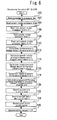
- Fig. 6 is a flowchart that represents a routine to process a data used for the determination of the failure of the intake valve 62.
- the routine shown in Fig. 6 is to be repeatedly executed for every 60°CA after the top dead center in each cylinder.
- the atmospheric pressure pa is read (step 100).
- the atmospheric pressure pa is always obtained and updated by use of the intake pressure sensor 56 during a stop of the internal combustion engine 12 or an operation in which the throttle valve opening degree is being fully opened, in accordance with a routine that is different from the present routine. According to such manner, the atmospheric pressure can be obtained without including an atmospheric pressure sensor separately.
- step 102 the current actual intake pressure pim obtained by use of the intake pressure sensor 56 is read (step 102), the actual intake pressure pim (i-1) of the last cycle (that is, at the crank an angle advanced by 180°CA) is read (step 104, the pseudo intake pressure pmcrt obtained by the processing of the routine shown in Fig. 7 described later is read (stop 106), and the pseudo intake pressure pmcrt of the last cycle (that is, at the crank an angle advanced by 180°CA) is read (step 108).
- the intake pressure difference dlpm (pmcrt - pim) is calculated (step 116)
- step 120 the current actual intake pressure pim is recorded (step 120), the current pseudo intake pressure pmcrt is recorded (step 122), and the current crank angle ccrnk is recorded (step 124). Then, a determination request for the stopping failure and the returning failure of the intake valve 62 is turned ON (step 126).
- Fig. 7 is a flowchart that represents a calculation processing routine of the pseudo intake pressure pmcrt.
- the routine shown in Fig. 7 first, the current throttle valve opening degree ta detected by use of the throttle position sensor 54 is read (step 200), the current engine speed ne detected by use of the crank angle sensor 72 is read (step 202), and the atmospheric pressure pa is read by means of the same processing as that of aforementioned step 100 (step 204).
- Fig. 8 is a diagram that represents a map that defines the pseudo intake pressure pmcrtb at the steady state with a relation with the throttle valve opening degree ta and the engine speed ne.
- the pseudo intake pressure pmcrtb at the steady state is calculated on the basis of the throttle valve opening degree ta and the engine speed ne, in accordance with a map as shown in Fig. 8 .
- step 210 it is determined whether or not the pseudo intake pressure pmcrtb at the steady state is higher than the atmospheric pressure pa (step 210). As a result of this, if it is determined that the pseudo intake pressure pmcrtb at the steady state is higher than the atmospheric pressure pa, the atmospheric pressure pa is assigned to the current pseudo intake pressure pmcrtb at the steady state (step 212).
- the smoothing process is executed with respect to the change amount between the last pseudo intake pressure pmcrto and the pseudo intake pressure pmcrtb at the steady state that is calculated in aforementioned step 208, and then, the current pseudo intake pressure pmcrt is calculated (step 214).
- the pseudo intake pressure pmcrt that is currently calculated is recorded as the last pseudo intake pressure pmcrto (step 216).
- Fig. 9 is a flowchart that represents a main routine of the failure determination processing for the intake valve 62 according to the first embodiment of the present invention.
- the routine shown in Fig. 9 first, it is determined whether or not the determination request for the stopping failure and the returning failure of intake valve 62 is in the ON state (step 300). As a result of this, if it is determined that the determination request is in the ON state, the processing to discriminate the cylinder number is performed in accordance with the routine shown in Fig. 10 .
- Fig. 10 is a flowchart that represents the routine of processing to discriminate the cylinder number that is subjected to the failure determination of the intake valve 62 at the time of start-up of the main routine.
- the routine shown in Fig. 10 first, the crank angle ccrnk1 recorded in aforementioned step 124 is read (step 400). Then, #3 cylinder is written (step 402).
- step 404 it is determined whether or not the crank angle ccrnk1 read in aforementioned step 400 is larger than or equal to 180°CA (step 404). As a result of this, if the present determination is negative, that is to say, if the aforementioned crank angle ccrnk1 is within 0 to 179°CA, the current cycle of the processing is ended. Thus, in this case, #3 cylinder written in aforementioned step 402 is discriminated as the determination target cylinder that is subjected to the current failure determination.
- step 406 If, on the other hand, the determination of aforementioned step 404 is positive, #4 cylinder is written (step 406). It is then determined whether or not the crank angle ccrnkl read in aforementioned step 400 is larger than or equal to 360°CA (step 408). As a result of this, if the present determination is negative, that is to say, if the aforementioned crank angle ccrnk1 is within 180 to 359°CA, the current cycle of the processing is ended. Thus, in this case, #4 cylinder written in aforementioned step 406 is discriminated as the determination target cylinder.
- step 408 determines whether or not the crank angle ccrnkl read in aforementioned step 400 is larger than or equal to 540°CA (step 412). As a result of this, if the present determination is negative, that is to say, if the aforementioned crank angle ccrnkl is within 360 to 539°CA, the current cycle of the processing is ended. Thus, in this case, #2 cylinder written in aforementioned step 410 is discriminated as the determination target cylinder.
- step 4114 If the determination of aforementioned step 412 is positive, #1 cylinder is written (step 414), and the current cycle of the processing is ended. Thus, in this case, #1 cylinder written in aforementioned step 414 is discriminated as the determination target cylinder.
- the routine shown in Fig. 9 will be described again. According to the routine shown in Fig. 9 , if the current determination target cylinder has been discriminated in aforementioned step 302 in accordance with the processing of the aforementioned routine shown in Fig. 10 , it is then determined whether or not the stopping request for the intake valve 62 is present (step 304).
- the stopping request for the intake valve 62 is issued when a predetermined execution condition of the stopping operation of the intake valve 62, such as the temperature of the catalyst 70 is higher than or equal to a predetermined temperature and a request to execute a fuel cut has been issued, is established.
- step 306 If it is determined in aforementioned step 304 that the stopping request for the intake valve 62 is present, the intake pressure rise time period tstp_pa calculated by the processing of the routine shown in Fig. 11 is read (step 306).
- Fig. 11 is a flowchart that represents the routine of processing to count up the intake pressure rise time period tstp_pa and the stopping time period tstpl.
- the present routine is executed periodically at predetermined intervals. According to the routine shown in Fig. 11 , first, it is determined whether or not the stopping request for the intake valve 62 is present by use of the same processing as that in aforementioned step 304. (step 500).
- the pressure difference dlpa (the value calculated by the processing in aforementioned step 118) between the atmospheric pressure pa and the actual intake pressure pim is read (step 502). Then, it is determined whether or not the pressure difference dlpa is higher than a predetermined determination value KDPA1 (step 504).
- step 504 If the determination of aforementioned step 504 is positive, it can be judged that since the actual intake pressure pim is away from the atmospheric pressure pa, the actual intake pressure pim is in a situation of increasing toward the atmospheric pressure pa, provided that the stopping operation of the intake valve 62 is normally performed. Because of this, in this case, the intake pressure rise time period tstp_pa is counted up (step 506), and the stopping time period tstp that is an elapsed time period from a time point at which the stopping request for the intake valve 62 has been issued is counted up (step 508). Then, the current stopping time period tstp is latched (recorded) as the stopping time period tstpl (step 510).
- the stopping time period tstp is counted up without counting up the intake pressure rise time period tstp_pa because of a situation in which the actual intake pressure pim is a value close to the atmospheric pressure pa (step 508).
- the time period can be calculated that is necessary for the actual intake pressure pim to arrive at a value near the atmospheric pressure pa after the stopping request has been issued, in a case in which the intake pressure rise time period tstp_pa has been counted up until the determination of aforementioned step 504 becomes negative from a state in which it is positive.
- the current stopping time period tstp is latched (recorded) as the stopping time period tstpl (step 510).
- step 500 determines whether the stopping request for the intake valve 62 is present. That is to say, if it can be judged to be at the time of an issuance of the returning request for the intake valve 62 or after the issuance, the intake pressure rise time period tstp_pa is cleared to be zero (step 514).
- step 306 After the intake pressure rise time period tstp_pa is read in aforementioned step 306, it is then determined whether or not there is the stopping failure of the intake valve 62, in accordance with the processing of the routine shown in Fig. 12 described later (step 308).
- step 304 If, on the other hand, it is determined in aforementioned step 304 that the stopping request for the intake valve 62 is not present, that is to say, if it can be judged to be at the time of an issuance of the returning request for the intake valve 62 or after the issuance, the stopping time period tstpl recorded in aforementioned step 510 is then read (step 310) and it is determined whether or not there is the returning failure of the intake valve 62 (step 312). In addition, in the routine shown in Fig. 9 , if the determination request is not the ON state (step 300), or if the stopping failure determination (step 308) or the returning failure determination (step 312) of the intake valve 62 is ended, the determination request is turned OFF (step 314).
- Fig. 12 is a flowchart that represents the routine of the stopping failure determination of the intake valve 62 in step 308 in Fig. 9 .
- the intake pressure change amount difference ddlpm calculated in aforementioned step 114 is read (step 600).
- the intake pressure difference dlpm calculated in aforementioned step 116 is read (step 602).
- step 604 it is determined whether or not the time period required to arrive at the atmospheric pressure after an issuance of the stopping request for the intake valve 62 is longer than that in a case in which the stopping operation is normal, that is to say, whether or not the aforementioned intake pressure rise time period tstp_pa is longer than or equal to the aforementioned predetermined arrival time period determination value ⁇ (step 604).
- step 604 determines whether or not the intake pressure change amount difference ddlpm is larger than a predetermined determination value KDDPM1 and the intake pressure difference dlpm is larger than a predetermined determination value KDPM (step 606).
- These determination values KDDPM1 and KDPM are values that are set in advance as threshold values for determining the stopping failure of the intake valve 62. As a result of this, if the determination of present step 606 is positive, it is determined that an abnormality has occurred in the stopping operation of the intake valve 62 in the current determination target cylinder, and a stopping abnormality counter cfailstp1 is counted up (step 608).
- step 610 it is determined whether or not the stopping abnormality counter cfailstp1 is larger than or equal to a predetermined value CFAIL1 (step 610). As a result of this, if the stopping abnormality counter cfailstp1 is determined to be larger than or equal to the aforementioned predetermined value CFAIL1, it is definitely determined that the stopping failure of the intake valve 62 has occurred at the current determination target cylinder, and the current determination result of the stopping failure is recorded (a stopping failure determination flag xfail1 is turned ON) (step 612).
- step 604 If, on the other hand, it is determined in aforementioned step 604 that the aforementioned intake pressure rise time period tstp_pa is longer than or equal to the aforementioned predetermined arrival time period determination value ⁇ , the stopping failure of the intake valve 62 has occurred in any of the cylinders, and the current determination result of the stopping failure is recorded (step 612).
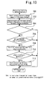
- Fig. 13 is a flowchart that represents the routine of the returning failure determination of the intake valve 62 in step 312 in Fig. 9 .
- the intake pressure change amount difference ddlpm calculated in aforementioned step 114 is read (step 700).
- the pressure difference dlpa calculated in aforementioned step 118 is read (step 702).
- the stopping time period tstpl immediately before an issuance of the current returning request for the intake valve 62 is longer than or equal to a predetermined value ⁇ (step 704). More specifically, on the premise of performing the failure determination by use of the atmospheric pressure pa in next step 706, it is determined by the processing of present step 704 whether or not the actual intake pressure pim at the time of an issuance of the returning request has arrived at a value near the atmospheric pressure pa.
- step 704 it is then determined whether or not the intake pressure change amount difference ddlpm is smaller than a predetermined determination value KDDPM2 and the pressure difference dlpa between the atmospheric pressure pa and the actual intake pressure pim is smaller than a predetermined determination value KDPA2 (step 706).
- These determination values KDDPM2 and KDPA2 are values that are set in advance as threshold values for determining the returning failure of the intake valve 62.
- the determination of present step 706 is positive, it is determined that an abnormality of the returning operation of the intake valve 62 has occurred at the current determination target cylinder, and a returning abnormality counter cfailrtn2 is counted up (step 708).
- step 710 it is determined whether or not the returning abnormality counter cfailrtn2 is larger than or equal to a predetermined value CFAIL2 (step 710). As a result of this, if the returning abnormality counter cfailrtn2 is larger than or equal to the aforementioned predetermined value CFAIL2, it is definitely determined that the returning failure of the intake valve 62 has occurred at the current determination target cylinder, and the current determination result of the returning failure is recorded (a returning failure determination flag xfai12 is turned ON) (step 712).
- the determination target cylinder of the failure is discriminated (identified), and on that basis, it is determined whether or not there is the stopping failure or the returning failure of the intake valve 62, in accordance whether or not the stopping request for the intake valve 62 is present.
- the determination can be performed by means of a slope of a change in the actual intake pressure pim in a situation in which the intake stroke transitions to the abnormal cylinder from the normal cylinder or a situation in which the intake stroke transitions to the normal cylinder from the abnormal cylinder. Because of this, in a case in which the actual intake pressure pim changes as shown in Fig. 3 , a cylinder at which the stopping failure has occurred can be identified.
- the determination using a large value is allowed in a case of using the intake pressure change amount difference ddlpm including the actual intake pressure change amount dlpim, as compared with a case of using the actual intake pressure pim alone.
- This makes it possible to improve the detection accuracy of the stopping failure.
- the actual intake pressure pim shows a change having the tendency similar to that of the pseudo intake pressure pmcrt.
- the actual intake pressure change amount dlpim or the intake pressure change amount difference ddlpm therewith as well as the intake pressure difference dlpm it can be grasped that the delay of the stopping of the intake valve 62 has been resolved, and thereby, the determination of the stopping failure can be performed more accurately.
- the routine shown in Fig. 12 if the time period required to arrive at the atmospheric pressure after an issuance of the stopping request for the intake valve 62 is longer than that in a case in which the stopping operation is normal, it is determined that the stopping failure of the intake valve 62 has occurred at any of the cylinders. Such determination can detect the stopping failure by use of the time period until the actual intake pressure pim arrives at the atmospheric pressure pa after the issuance of the stopping request for the intake valve 62.
- a cylinder at which the returning failure has occurred can be identified in a case in which the actual intake pressure pim changes as shown in Fig. 5 , for the season similar to that described for a case of the stopping failure. Furthermore, the determination using a large value (nearly double) is allowed as compared with a case of using the actual intake pressure change amount dlpim alone. This makes it possible to improve the detection accuracy of the returning failure.
- the failure determination based on the intake pressure difference dlpm and the failure determination based on the intake pressure change amount difference ddlpm are combined with each other.
- the present invention is not limited to this manner, and for example, the following manner may be adopted. More specifically, the failure determination based on the intake pressure difference dlpm may be performed alone. As already described, when the stopping failure has occurred, the difference between the actual intake pressure pim and the pseudo intake pressure pmcrt is produced. Therefore, even when the failure determination based on the intake pressure difference dlpm is performed alone, it can be determined that the stopping failure has occurred at any of the cylinders.
- the failure determination based on the actual intake pressure change amount dlpim may be performed in addition to the failure determination based on the intake pressure difference dlpm.
- the actual intake pressure change amount dlpim becomes a negative value because the actual intake pressure pim decreases. Therefore, by determining whether the actual intake pressure change amount dlpim is positive or negative, a cylinder at which the stopping failure has occurred can be identified.
- the failure determination based on the intake pressure change amount difference ddlpm and the failure determination based on the pressure difference dlpa between the atmospheric pressure pa and the actual intake pressure pim are combined with each other.
- the present invention is not limited to this manner, and for example, the following manner may be adopted. More specifically, the failure determination based on the intake pressure difference dlpm may be performed alone, as with the case of determining the stopping failure. As already described, also when the returning failure has occurred, the difference between the actual intake pressure pim and the pseudo intake pressure pmcrt is produced.
- the failure determination based on the intake pressure difference dlpm may be performed in addition to the failure determination based on the intake pressure change amount difference ddlpm.
- the difference between the pseudo intake pressure pmcrt and the actual intake pressure pim that becomes a value near the atmospheric pressure pa increases.
- the intake pressure difference dlpm first difference obtained by subtracting the actual intake pressure pim at a predetermined crank angle associated with a predetermined determination target cylinder (for example, 60°CA after the top dead center) from the pseudo intake pressure pmcrt at the predetermined crank angle is smaller than a predetermined fifth determination value
- the intake pressure change amount difference ddlpm second difference obtained by subtracting the actual intake pressure change amount dlpim at a predetermined crank angle period associated with the determination target cylinder (in a four-cylinder engine, interval of 180°CA) from the pseudo intake pressure change amount dlpmcrt at the predetermined crank angle period is smaller than a predetermined sixth determination value.
- the failure determination based on the actual intake pressure change amount dlpim may be performed in addition to the failure determination based on the intake pressure difference dlpm, as with the case of determining the stopping failure of the intake valve 62.
- the actual intake pressure change amount dlpim becomes a positive value because the actual intake pressure pim increases. Therefore, by determining whether the actual intake pressure change amount dlpim is positive or negative, a cylinder at which the returning failure has occurred can be identified.
- the present invention is not limited to the application to a system in which an internal combustion engine having a valve stop mechanism is mounted on a hybrid vehicle, and can be similarly applied to a vehicle that is driven only by an internal combustion engine having a valve stop mechanism as a power source.
- the internal combustion engine 12 of a straight four-cylinder type description has been made by taking an example of the internal combustion engine 12 of a straight four-cylinder type.
- the internal combustion engine to be addressed in the present invention is not limited to the straight four-cylinder type. More specifically, the present invention can be also applied to another type of an internal combustion engine by arbitrarily changing a crank angle and a crank angle period that are used for the failure determination processing.
- the ECU40 executes a series of the processing of the above described routine shown in Fig. 7 , whereby the "pseudo intake pressure obtaining means" according to the first aspect of the present invention is realized, the ECU 40 executes the above described processing of steps 606 and 608, whereby the "first failure determination means” according to the first aspect of the present invention is realized, and the ECU 40 executes a series of the processing of the above described main routine shown in Fig. 9 , whereby the "failure determination means" according to the first aspect of the present invention is realized.
- 60°CA after the top dead center corresponds to the "predetermined crank angle” according to the first aspect of the present invention
- the intake pressure difference dlpm corresponds to the "first difference” according to the first aspect of the present invention.
- the ECU40 executes the above described processing of steps 106 and 108, whereby the "second failure determination means" according to the second aspect of the present invention is realized.
- the interval of 180°CA corresponds to the "predetermined crank angle period" according to the second aspect of the present invention.
- the intake pressure change amount difference ddlpm corresponds to the "second difference" according to the third aspect of the present invention.
- the ECU40 executes the above described processing of step 100, whereby the "atmospheric pressure obtaining means” according to the fourth aspect of the present invention is realized, and the ECU40 executes the above described processing of steps 706 and 708, whereby the "third failure determination means” according to the fourth aspect of the present invention is realized.
- the pressure difference dlpa corresponds to the "third difference" according to the fourth aspect of the present invention.
- the ECU40 executes the above described processing of steps 604 and 612, whereby the "fourth failure determination means" according to the fifth aspect of the present invention is realized. Moreover, in the first embodiment, which has been described above, the ECU40 executes a series of the processing of the above described routine shown in Fig. 10 , whereby the "cylinder discrimination means" according to the sixth to eighth aspects of the present invention is realized.
- the determination value KDPM corresponds to the "first determination value” according to the sixth aspect of the present invention
- the determination value KDDPM1 corresponds to the "second determination value” according to the sixth aspect of the present invention.
- the determination value KDPA2 corresponds to the "third determination value” according to the seventh aspect of the present invention
- the determination value KDDPM2 corresponds to the "fourth determination value” according to the seventh aspect of the present invention.
Landscapes
- Engineering & Computer Science (AREA)
- Chemical & Material Sciences (AREA)
- Combustion & Propulsion (AREA)
- Mechanical Engineering (AREA)
- General Engineering & Computer Science (AREA)
- Transportation (AREA)
- Combined Controls Of Internal Combustion Engines (AREA)
- Output Control And Ontrol Of Special Type Engine (AREA)
- Valve-Gear Or Valve Arrangements (AREA)
Abstract
Description
- The present invention relates to a control apparatus for an internal combustion engine, and more particular to a control apparatus for an internal combustion engine that is suitable for determining whether or not there is a failure concerning a switching of an operational state of an intake valve, in the internal combustion engine that includes a valve stop mechanism that is capable of switching the operational state of the intake valve between a valve operating state and a valve closed/stopped state.
- So far, for example,
Patent Document 1 discloses a failure detecting device for an internal combustion engine that includes electromagnetically-driven type intake and exhaust valves. The conventional failure detecting device detects a failure of the intake and exhaust valves at the time of normal operation of the internal combustion engine in which the opening and closing of the intake and exhaust valves are being performed. More specifically, the aforementioned failure detecting device determines whether or not there is a failure of the intake valve being opened on the basis of the width of a change in an intake pipe pressure at a predetermined crank angle period, and determines whether or not there is a failure of the intake valve at a closed state or a failure of the exhaust valve being opened or closed, on the basis of the width of a change in an average value of the intake pipe pressure among cylinders.
Including the above described document, the applicant is aware of the following documents as related art of the present invention. -
- Patent Document 1: Japanese Laid-open Patent Application Publication No.
2000-73792 - Patent Document 2: Japanese Laid-open Patent Application Publication No.
2004-100487 - Patent Document 3: Japanese Laid-open Patent Application Publication No.
2004-100486 - Also in an internal combustion engine that includes a valve stop mechanism which is capable of switching an operational state of an intake valve between a valve operating state and a closed/stopped state, it is desirable to be able to determine whether or not there is a failure concerning the operational state of the intake valve, without the need of newly providing a costly sensor, such as a lift amount sensor that is capable of detecting a lift amount of the intake valve.
- The present invention has been made to solve the problem as described above, and has its object to provide a control apparatus for an internal combustion engine, which can determine whether or not there is a failure concerning a switching of an operational state of an intake valve, in the internal combustion engine that includes a valve stop mechanism that is capable of switching the operational state of the intake valve between a valve operating state and a valve closed/stopped state, without the need of adding a new sensor for the failure determination.
- A first aspect of the present invention is a control apparatus for an internal combustion engine, comprising:
- a valve stop mechanism that is capable of switching an operational state of an intake valve between a valve operating state and a valve closed/stopped state;
- a crank angle sensor for detecting a crank angle of an internal combustion engine;
- an intake pressure sensor for detecting an actual intake pressure;
- pseudo intake pressure obtaining means for obtaining, based on an operational condition of the internal combustion engine, a pseudo intake pressure in a situation in which a switching of the operational state between the valve operating state and the valve closed/stopped state is normally performed; and
- failure determination means that includes first failure determination means for determining whether or not there is a failure concerning the switching of the operational state of the intake valve between the valve operating state and the valve closed/stopped state by the valve stop mechanism, based on a first difference between the actual intake pressure and the pseudo intake pressure at a predetermined crank angle.
- A second aspect of the present invention is the control apparatus for an internal combustion engine according to the first aspect of the present invention,
wherein the failure determination means includes second failure determination means for determining whether or not there is the failure concerning the switching of the operational state of the intake valve between the valve operating state and the valve closed/stopped state by the valve stop mechanism, based on a change amount of the actual intake pressure at a predetermined crank angle period. - A third aspect of the present invention is the control apparatus for an internal combustion engine according to the second aspect of the present invention,
wherein the second failure determination means determines whether or not there is a failure concerning the switching of the operational state of the intake valve between the valve operating state and the valve closed/stopped state by the valve stop mechanism, based on a second difference between the change amount of the actual intake pressure at the predetermined crank angle period and a change amount of the pseudo intake pressure at the predetermined crank angle period. - A fourth aspect of the present invention is the control apparatus for an internal combustion engine according to any one of the first to third aspects of the present invention,
wherein the control apparatus of the internal combustion engine further comprises atmospheric pressure obtaining means for obtaining an atmospheric pressure, and
wherein the failure determination means includes third failure determination means for determining whether or not there is a failure concerning a returning operation of the intake valve to switch the valve closed/stopped state to the valve operating state, based on a third difference between the actual intake pressure and the atmospheric pressure when a returning request to switch the valve closed/stopped state to the valve operating state for the intake valve has been issued. - A fifth aspect of the present invention is the control apparatus for an internal combustion engine according to any one of the first to fourth aspects of the present invention,
wherein the failure determination means includes fourth failure determination means for, when a time period necessary for the actual intake pressure to arrive at the atmospheric air pressure is longer than or equal to a predetermined arrival time period determination value in a case in which a stopping request to switch the valve operating state to the valve closed/stopped state for the intake valve is present, determining that a failure concerning a stopping operation of the intake valve for switching the valve operating state to the valve closed/stopped state has occurred. - A sixth aspect of the present invention is the control apparatus for an internal combustion engine according to the third aspect of the present invention,
wherein the control apparatus for an internal combustion engine further comprises cylinder discrimination means for discriminating a determination target cylinder that is subjected to failure determination, on a basis of the crank angle that is detected by the crank angle sensor, and
wherein the failure determination means determines that a failure concerning a stopping operation of the intake valve for switching the valve operating state to the valve closed/stopped state has occurred at the determination target cylinder, when the first difference that is obtained by subtracting the actual intake pressure at the predetermined crank angle associated with the determination target cylinder from the pseudo intake pressure at the predetermined crank angle is larger than a predetermined first determination value, and the second difference that is obtained by subtracting the change amount of the actual intake pressure at the predetermined crank angle period associated with the determination target cylinder from the change amount of the pseudo intake pressure at the predetermined crank angle period is larger than a predetermined second determination value, in a case in which a stopping request to switch the valve operating state to the valve closed/stopped state for the intake valve is present. - A seventh aspect of the present invention is the control apparatus for an internal combustion engine according to the fourth or sixth aspect of the present invention,
wherein the control apparatus for an internal combustion engine further comprises cylinder discrimination means for discriminating a determination target cylinder that is subjected to failure determination, on a basis of the crank angle that is detected by the crank angle sensor, and
wherein the failure determination means determines that a failure concerning a returning operation of the intake valve for switching the valve closed/stopped state to the valve operating state has occurred at the determination target cylinder, when the third difference that is obtained by subtracting the actual intake pressure at the predetermined crank angle associated with the determination target cylinder from the atmospheric air pressure is smaller than a predetermined third determination value, and the second difference that is obtained by subtracting the change amount of the actual intake pressure at the predetermined crank angle period associated with the determination target cylinder from the change amount of the pseudo intake pressure at the predetermined crank angle period is smaller than a predetermined fourth determination value, in a case in which a stopping request to switch the valve operating state to the valve closed/stopped state for the intake valve is present. - An eighth aspect of the present invention is the control apparatus for an internal combustion engine according to the third, sixth, seventh or eighth aspect of the present invention,
wherein the control apparatus for an internal combustion engine further comprises cylinder discrimination means for discriminating a determination target cylinder that is subjected to failure determination, on a basis of the crank angle that is detected by the crank angle sensor, and
wherein the failure determination means determines that a failure concerning a returning operation of the intake valve for switching the valve closed/stopped state to the valve operating state has occurred in the determination target cylinder, when the first difference that is obtained by subtracting the actual intake pressure at the predetermined crank angle associated with the determination target cylinder from the pseudo intake pressure at the predetermined crank angle is larger than a predetermined fifth determination value, and the second difference that is obtained by subtracting the change amount of the actual intake pressure at the predetermined crank angle period associated with the determination target cylinder from the change amount of the pseudo intake pressure at the predetermined crank angle period is smaller than a predetermined sixth determination value, in a case in which a returning request to switch the valve closed/stopped state to the valve operating state for the intake valve is present. - When a failure has occurred in the switching of the operational state of the intake valve between the valve operating state and the valve closed/stopped state, the difference is produced between the actual intake pressure and the aforementioned pseudo intake pressure. According to the first aspect of the present invention, it can be therefore determined whether or not there is the failure by performing the determination of using the first difference between the actual intake pressure and the pseudo intake pressure at a predetermined crank angle, without the need of adding a new sensor for the failure determination.
- According to the second aspect of the present invention, a cylinder at which the aforementioned failure of the intake valve has occurred can be identified by performing the determination of using the change amount of the actual intake pressure at a predetermined crank angle period.
- According to the third aspect of the present invention, the determination of the failure using a large value is allowed as compared with a case of only using the change amount of the actual intake pressure at the predetermined crank angle period. This makes it possible to improve the accuracy of determination of the aforementioned failure.
- When a failure of the intake valve has occurred in the returning operation, after the returning request the difference between the atmospheric pressure and the actual intake pressure is not produced or becomes small even if it has been produced. According to the fourth aspect of the present invention, it can be determined whether or not there is a failure of the returning operation of the intake valve by performing the determination of using the third difference between the actual intake pressure and the atmospheric pressure.
- When the stopping operation of the intake valve is not normally performed at the time of the stopping request for the intake valve, the actual intake pressure does not rise to a value near the atmospheric pressure even when a time period has elapsed that is required for the actual intake pressure to arrive at a value near the atmospheric pressure if the stopping operation of the intake valve is normally performed. According to the fifth aspect of the present invention, when the stopping request has been issued, it can be determined that a failure concerning the stopping operation of the intake valve has occurred by determining whether or not the time period until the actual intake pressure arrives at the atmospheric pressure is longer than or equal to a predetermined arrival time period determination value.
- When the stopping request for the intake valve has been issued, the sixth aspect of the present invention makes it possible to accurately determine a cylinder at which a failure concerning the stopping operation of the intake valve has occurred.
- When the returning request for the intake valve has been issued, the seventh to eighth aspects of the present invention make it possible to accurately determine a cylinder at which a failure concerning the returning operation of the intake valve has occurred.
-
-
Fig. 1 is a diagram to show an outline configuration of a drive system of a hybrid vehicle to which the present invention is applied; -
Fig. 2 is a diagram for explaining the system configuration of an internal combustion engine shown inFig. 1 ; -
Fig. 3 is a diagram for explaining a determination method of a stopping failure of an intake valve by use of a case in which an one-cycle delay of a stopping operation of the intake valve has occurred at #1 and #4 cylinders; -
Fig. 4 is a diagram for explaining a determination method of the stopping failure of the intake valve by use of a case in which two-cycle delays of the stopping operations of the intake valves have occurred at all of the cylinders; -
Fig. 5 is a diagram for explaining a determination method of a returning failure of the intake valve with reference to a case in which an one-cycle delay of a returning operation of the intake valve has occurred at #1 and #4 cylinders; -
Fig. 6 is a flowchart that represents a routine to process a data used for the determination of the failure of the intake valve; -
Fig. 7 is a flowchart that represents a calculation processing routine of a pseudo intake pressure pmcrt; -
Fig. 8 is a diagram that represents a map that defines the pseudo intake pressure pmcrtb at the steady state with a relation with a throttle valve opening degree ta and an engine speed ne; -
Fig. 9 is a flowchart that represents a main routine of the failure determination processing for the intake valve according to the first embodiment of the present invention; -
Fig. 10 is a flowchart that represents the routine of processing to discriminate the cylinder number that is subjected to the failure determination of the intake valve at the time of start-up of the main routine; -
Fig. 11 is a flowchart that represents the routine of processing to count up an intake pressure rise time period tstp_pa and a stopping time period tstpl; -
Fig. 12 is a flowchart that represents the routine of the stopping failure determination of the intake valve instep 308 inFig. 9 ; and -
Fig. 13 is a flowchart that represents the routine of the returning failure determination of the intake valve instep 312 inFig. 9 . -
Fig. 1 is a diagram to show an outline configuration of adrive system 10 of a hybrid vehicle to which the present invention is applied. Thisdrive system 10 includes a motor for driving the vehicle (hereafter, simply referred to as a "motor") 14 as the second power source for the vehicle in addition to aninternal combustion engine 12. In addition, thedrive system 10 also includes agenerator 16 that receives the supply of a driving force to generate electric power. Theinternal combustion engine 12, themotor 14 and thegenerator 16 are interlinked via apower split mechanism 18 of a planetary gear type. Aspeed reducer 20 is connected to the rotating shaft of themotor 14 in connection with thepower split mechanism 18. Thespeed reducer 20 links the rotating shaft of themotor 14 with a drivingshaft 24 which leads to drivingwheels 22. Thepower split mechanism 18 is an apparatus to split the driving force of theinternal combustion engine 12 into thegenerator 16 side and thespeed reducer 20 side. The distribution of the driving force by thepower split mechanism 18 can be freely changed. - The
drive system 10 further includes aninverter 26, aconverter 28 and ahigh voltage battery 30. Theinverter 26 is connected to thegenerator 16 and themotor 14, and is also connected to thehigh voltage battery 30 via theconverter 28. The electric power generated at thegenerator 16 can be supplied to themotor 14 via theinverter 26, and also can be charged to thehigh voltage battery 30 via theinverter 26 and theconverter 28. Moreover, the electric power charged in thehigh voltage battery 30 can be supplied to themotor 14 via theconverter 28 and theinverter 26. - According to the
drive system 10 as so far described, based on a predetermined condition the drivingwheels 22 can be rotated by the driving force of theinternal combustion engine 12 alone with themotor 14 being deactivated, and conversely the drivingwheels 22 can be rotated by the driving force of themotor 14 alone with theinternal combustion engine 12 being deactivated. Moreover, it is also possible to activate both of themotor 14 and theinternal combustion engine 12 and to rotate the drivingwheels 22 by both of the driving forces. Further, thegenerator 16 is allowed to function as a starter to drive theinternal combustion engine 12, and thereby, the start up of theinternal combustion engine 12 can be controlled. - The
drive system 10 of the present embodiment is controlled by an ECU (Electronic Control Unit) 40. TheECU 40 comprehensively controls theentire drive system 10 including theinternal combustion engine 12, themotor 14, thegenerator 16, thepower split mechanism 18, theinverter 26, theconverter 28 and the like. -
Fig. 2 is a diagram for explaining the system configuration of theinternal combustion engine 12 shown inFig. 1 . Here, theinternal combustion engine 12 is supposed to be a straight four-cylinder engine which includes four cylinders (#1 to #4) and in which explosion strokes are performed at uniform intervals in the order (for example) of #1 to #3, to #4, and to #2. Each of cylinders of theinternal combustion engine 12 contains apiston 42. Each of the cylinders of theinternal combustion engine 12 has a combustion chamber 44 formed atop thepiston 42. Anintake passage 46 and anexhaust passage 48 are communicated with the combustion chamber 44. - An
air flow meter 50 is installed in the vicinity of the inlet of theintake passage 46 to output a signal representing the flow rate of the air taken into theintake passage 46. Athrottle valve 52 is installed downstream of theair flow meter 50. Thethrottle valve 52 is an electronically controlled throttle valve that can control an opening degree of the throttle valve independently of a press-down degree of an accelerator. A throttlevalve position sensor 54 for detecting the throttle valve opening degree is disposed in the vicinity of thethrottle valve 52. - An
intake pressure sensor 56 for detecting an intake pressure is disposed downstream with respect to thethrottle valve 52, more specifically, the integral part of an intake manifold of theintake passage 14. In addition, afuel injection valve 58 for injecting a fuel into an intake port of theinternal combustion engine 12 is disposed downstream with respect to theintake pressure sensor 56. At a cylinder head of theinternal combustion engine 12, anignition plug 60 is mounted in such a form as to project from an upper section of the combustion chamber 44 into the combustion chamber 44. Anintake valve 62 and anexhaust valve 64 are provided at the intake port and an exhaust port, respectively. Theintake valve 62 establishes continuity or discontinuity between the combustion chamber 44 and theintake passage 46, and theexhaust valve 64 establishes continuity or discontinuity between the combustion chamber 44 and theexhaust passage 48. - The
intake valve 62 and theexhaust valve 64 are driven by an intake variablevalve operating apparatus 66 and an exhaust variablevalve operating apparatus 68, respectively. It is assumed that the intake variablevalve operating apparatus 66 includes a valve stop mechanism (not shown) that is capable of switching the operational state of theintake valve 62 between the valve operating state and the valve closed/stopped state for each cylinder, and similarly, the exhaust variablevalve operating apparatus 68 includes a valve stop mechanism (not shown) that is capable of switching the operational state of theexhaust valve 64 between the valve operating state and the valve closed/stopped state for each cylinder. The concrete configurations of the aforementioned valve stop mechanisms are not specifically limited, and can be realized by means of, for example, a configuration that is capable of halting a rocking action of a rocker arm that transmits an acting force of a cam to a valve using a switching pin. - Furthermore, a
catalyst 70 for purifying exhaust gas is disposed in theexhaust passage 48. Moreover, an input section of theaforementioned ECU 40 is connected with various types of sensors for detecting the operating state of theinternal combustion engine 12, such as acrank angle sensor 72 for detecting a crank angle and an engine speed (crank angular velocity), as well as theair flow meter 50, the throttlevalve position sensor 54 and theintake pressure sensor 56 that are described above. Furthermore, an output section of theECU 40 is connected with various types of actuators for controlling theinternal combustion engine 12 as well as thethrottle valve 52, thefuel injection valve 58, theignition plug 60, the intake variablevalve operating apparatus 66 and the exhaust variablevalve operating apparatus 68 that are described above. TheECU 40 can control the operating state of theinternal combustion engine 12 on the basis of outputs of those sensors. - If fresh air that has a high oxygen concentration is supplied into the
catalyst 70 in a case in which thecatalyst 70 that is disposed in theexhaust passage 48 is in a high temperature state, there is a concern that deterioration of thecatalyst 70 will arise. In order to suppress the deterioration of thecatalyst 70, it is effective to prevent the oxygen from flowing into thecatalyst 70. According to the system of the present embodiment that includes the aforementioned variablevalve operating apparatuses intake valve 62 and theexhaust valve 64 in all cylinders is switched to the valve closed/stopped state from the valve operating state in synchronization with the fuel cut, and thereby, the oxygen can be prevented from flowing into thecatalyst 70 during the fuel cut. This makes it possible to suppress the deterioration of thecatalyst 70. - Hereinafter, a method for determining whether or not there is a failure concerning a switching of the operational state of the
intake valve 62 between the valve operating state and the valve closed/stopped state will be described with reference toFigs. 3 to 5 . More specifically, when a request to execute a fuel cut that is accompanied by a stopping request to switch the valve operating state to the valve closed/stopped state for theintake valve 62 has been issued, the present embodiment performs a determination as to whether or not there is a failure concerning a stopping operation of theintake valve 62 for switching the valve operating state to the valve closed/stopped state, that is to say, a failure (hereinafter, simply referred to as a "stopping failure" in some cases) in which a switching toward the valve closed/stopped state is not normally performed in synchronization with the fuel cut, by use of a method that is described below with reference toFigs. 3 and 4 . In addition, when a returning request from a fuel cut that is accompanied by a returning request to switch the valve closed/stopped state to the valve operating state for theintake valve 62 has been issued, the present embodiment performs a determination as to whether or not there is a failure concerning a returning operation of theintake valve 62 for switching the valve closed/stopped state to the valve operating state, that is to say, a failure (hereinafter, simply referred to as a "returning failure" in some cases) in which a switching toward the valve operating state is not normally performed in synchronization with the returning from the fuel cut, has occurred, by use of a method that is described below with reference toFig. 5 . In this connection, the following description is assumed to be made by taking an example of a situation in which a stopping request and a returning request are issued with respect to the intake valves in a plurality of cylinders that shares an intake manifold of an intake passage (in theinternal combustion engine 12 of the present embodiment, all cylinders of #1 to #4 correspond to them). -
Fig. 3 is a diagram for explaining a determination method of the stopping failure of theintake valve 62 by use of a case in which an one-cycle delay of the stopping operation of theintake valve 62 has occurred at #1 and #4 cylinders, andFig. 4 is a diagram for explaining a determination method of the stopping failure of theintake valve 62 by use of a case in which two-cycle delays of the stopping operations of theintake valves 62 have occurred at all of the cylinders. More specifically,Figs. 3 and 4 are diagrams representing the operation of theinternal combustion engine 12 before and after execution of a fuel cut that is accompanied by the stopping operations of theintake valves 62 in all of the cylinders at the time of deceleration. In addition, the waveforms represented by the solid lines inFigs. 3(C) and 4(C) (the same asFig. 5(C) ) correspond to an actual intake pressure pim, and the waveforms represented by the one-dot chain lines in the same figures correspond to a pseudo intake pressure pmcrt. The pseudo intake pressure pmcrt is a value that is calculated on the basis of the operating condition of the internal combustion engine 12 (herein, the engine speed and the throttle valve opening degree), and corresponds to a value (estimated value) that is equivalent to the actual intake pressure pim in a case in which the stopping operation or the returning operation of theintake valve 62 has been normally performed in each cylinder. In this connection, inFigs. 3 and 4 (the same asFig. 5 ), the crank angle when thepiston 42 in #1 cylinder is located at the compression top dead center corresponds to 0°CA. Furthermore, inFigs. 3 and 4 (the same asFig. 5 ), the acquisition timing of the actual intake pressure pim and the pseudo intake pressure pmcrt correspond to 60°CA after the top dead center in each cylinder, which is a timing at which the intake pressure pulsation for every cylinder shows a peak value. - As shown in
Figs. 3(C) and 4(C) , the actual intake pressure pim in a case in which theintake valve 62 is in operation at the time of deceleration is gradually decreasing (increasing in terms of negative pressure) because thethrottle valve 52 is in the closed state. If under such a situation the stopping operation of theintake valve 62 of each cylinder has been normally performed, the flow of intake gas stops, and therefore, the actual intake pressure pim increases toward the atmospheric pressure pa as in the pseudo intake pressure pmcrt. If, on the other hand, the stopping failure of theintake valve 62 has occurred as shown inFigs. 3 and 4 , the flow of the intake gas is generated through a cylinder at which the stopping failure has occurred, and therefore, the actual intake pressure pim decreases. More specifically, if it is a case where the cylinders at which the stopping failure has occurred are intermittently present as shown inFig. 3 : the actual intake pressure pim increases in the intake stroke of #3 cylinder at which the stopping operation is being normally performed because the intake gas does not flow; then, the actual intake pressure pim decreases in the intake stroke of #1 cylinder at which the failure has occurred because the intake gas flows; then, the actual intake pressure pim increases again in the intake stroke of #2 cylinder that is normal; and then, the actual intake pressure pim decreases again in the intake stroke of #4 cylinder at which the failure has occurred because the intake gas does not flow. In addition, if it is a case where the stopping failure has occurred continuously in all cylinders as shown inFig. 4 , the actual intake pressure pim decreases in succession in two cycles during which the stopping failure has occurred. - Accordingly, in the present embodiment, the stopping failure of the
intake valve 62 is detected, and further, a cylinder at which the stopping failure has occurred is identified, by use of the following method. More specifically, the pseudo intake pressure pmcrt calculated on the basis of the operating condition as described above represents a value equivalent to the actual intake pressure pim at the normal state, and therefore, an intake pressure difference dlpm between the actual intake pressure pim and the pseudo intake pressure pmcrt increases when the stopping failure has occurred. Thus, in the present embodiment, a determination of the stopping failure of theintake valve 62 based on the intake pressure difference dlpm is performed. - In addition, as depicted well in
Fig. 3 , the actual intake pressure pim increases and decreases in synchronization with the intake strokes of the normal cylinder and the failure cylinder (that is, for every 180°CA in the four-cylinder engine as in the internal combustion engine 12). As a result of this, a change amount dlpim (the current value pim - the last value pim(i - 1)) of the actual intake pressure pim at 240°CA after the intake top dead center (a timing near the closing timing of the intake valve) in each cylinder becomes a negative value if the intake stroke transitions to the failure cylinder from the normal cylinder, and on the contrary, becomes a positive value if the intake stroke transitions to the normal cylinder from the failure cylinder. Because of this, a cylinder at which the stopping failure has occurred can be identified on the basis of the actual intake pressure change amount dlpim. - Further, a change amount dlpmcrt (pmcrt - pmcrt(i - 1)) of the pseudo intake pressure pmcrt during the stopping operation of the
intake valve 62 becomes a positive value during a period in which the pseudo intake pressure pmcrt is rising toward the atmospheric pressure pa. As a result of this, ddlpm (dlpmcrt - dlpim), which is the difference between these two change amounts, becomes a large positive value because when the intake stroke transitions to the failure cylinder from the normal cylinder, the difference between the positive value dlpmcrt and the negative value dlpim corresponds to it, and, on the other hand, becomes a value close to zero because when the intake stroke transitions to the normal cylinder from the failure cylinder, the difference between the positive value dlpmcrt and the positive value dlpim corresponds to it. The determination of the failure using a large value (nearly double) is therefore allowed in a case of using the intake pressure change amount difference ddlpm when identifying a cylinder at which the stopping failure has occurred, as compared with a case of using the actual intake pressure change amount dlpim. Accordingly, in the present embodiment, the determination of the stopping failure of theintake valve 62 based on the intake pressure change amount difference ddlpm is also performed as well as the determination of the stopping failure of theintake valve 62 based on the intake pressure difference dlpm. - Further, in a case in which the number of stopping delay cycles of the
intake valve 62 is large, the actual intake pressure pim does not rise to a value near the atmospheric pressure pa even when a time period has elapsed that is necessary for the actual intake pressure pim to arrive at a value near the atmospheric pressure pa if the stopping operation of theintake valve 62 has been normally performed. Therefore, the present embodiment further determines that the stopping failure of theintake valve 62 has occurred at any of cylinders if a rise time period tstp_pa of the actual intake pressure pim from a time point at which a stopping request for theintake valve 62 has been issued is longer than or equal to a predetermined arrival time period determination value α (a time period necessary for the actual intake pressure pim to arrive at the atmospheric pressure pa if the stopping operation of theintake valve 62 is normal). -
Fig. 5 is a diagram for explaining a determination method of the returning failure of theintake valve 62 with reference to a case in which an one-cycle delay of the returning operation of theintake valve 62 has occurred at #1 and #4 cylinders.
When a stopping time period tstp of theintake valve 62 is longer than or equal to a predetermined time period, the actual intake pressure pim arrives at the atmospheric pressure pa during a period in which the stopping operation of theintake valve 62 continues. If the returning operation of theintake valve 62 of each cylinder has been normally performed under such a situation, the intake gas starts to flow, and as a result, the actual intake pressure pim decreases as in the pseudo intake pressure pmcrt inFig. 5 . If, on the other hand, the returning failure of theintake valve 62 has occurred, the intake gas does not flow, and as a result, the actual intake pressure pim holds a value near the atmospheric pressure pa or rises again, as shown inFig. 5 . - Accordingly, in the present embodiment, the determination of the returning failure of the
intake valve 62 is performed on the basis of the intake pressure change amount difference ddlpm when a returning request for theintake valve 62 has been issued, in the same manner as when the above described stopping request has been issued. Specifically, as shown inFig. 5 , the pseudo intake pressure change amount dlpmcrt becomes a negative value in the course of the actual intake pressure pim decreasing after the returning request, and approaches nearly zero after that. In contrast, as shown inFig. 5 , the actual intake pressure change amount dlpim becomes a positive value because the actual intake pressure pim increases if the intake stroke transitions to the failure cylinder from the normal cylinder, and conversely, becomes a negative value because the actual intake pressure pim decreases if the intake stroke transitions to the normal cylinder from the failure cylinder. Thus, a cylinder at which the returning failure has occurred can be identified on the basis of the actual intake pressure change amount dlpim. On that basis, the intake pressure change amount difference ddlpm becomes a large negative value because the difference between the negative value dlpmcrt and the positive value dlpim corresponds to it if the intake stroke transitions to the failure cylinder from the normal cylinder, and on the other hand, becomes a value near zero because the difference between the negative value dlpmcrt and the negative value dlpim corresponds to it if the intake stroke transitions to the normal cylinder from the failure cylinder. Therefore, also when identifying a cylinder at which the returning failure has occurred, the determination of the failure by use of a large value (nearly double) can be performed in a case of using the intake pressure change amount difference ddlpm, as compared with a case of using the actual intake pressure change amount dlpim. - Further, when the retuning failure of the
intake valve 62 has occurred, the actual intake pressure pim becomes a value near the atmospheric pressure pa. In the present embodiment, the further determination of the returning failure of theintake valve 62 is performed on the basis of a pressure difference dlpa (pa - pim) between the atmospheric pressure pa and the actual intake pressure pim. - Hereinafter, the concrete processing that is executed by the
ECU 40 to determine whether or not there are the stopping failure and the returning failure of theintake valve 62 that are described above will be described with reference toFigs. 6 to 13 .
First,Fig. 6 is a flowchart that represents a routine to process a data used for the determination of the failure of theintake valve 62. The routine shown inFig. 6 is to be repeatedly executed for every 60°CA after the top dead center in each cylinder. - According to the routine shown in
Fig. 6 , first, the atmospheric pressure pa is read (step 100). The atmospheric pressure pa is always obtained and updated by use of theintake pressure sensor 56 during a stop of theinternal combustion engine 12 or an operation in which the throttle valve opening degree is being fully opened, in accordance with a routine that is different from the present routine. According to such manner, the atmospheric pressure can be obtained without including an atmospheric pressure sensor separately. - Next, the current actual intake pressure pim obtained by use of the
intake pressure sensor 56 is read (step 102), the actual intake pressure pim (i-1) of the last cycle (that is, at the crank an angle advanced by 180°CA) is read (step 104, the pseudo intake pressure pmcrt obtained by the processing of the routine shown inFig. 7 described later is read (stop 106), and the pseudo intake pressure pmcrt of the last cycle (that is, at the crank an angle advanced by 180°CA) is read (step 108). - Next, the actual intake pressure change amount dlpim (= the current value pim - the last value pim (i - 1)) is calculated (step 110), the pseudo intake pressure change amount dlpmcrt (= the current value pmcrt - the last value pmcrt (i - 1)) is calculated (step 112), the intake pressure change amount difference ddlpm (= dlpmcrt - dlpim) is calculated (step 114), the intake pressure difference dlpm (pmcrt - pim) is calculated (step 116), and the pressure difference dlpa (= pa - pim) between the atmospheric pressure pa and the actual intake pressure pim is calculated (step 118).
- Next, the current actual intake pressure pim is recorded (step 120), the current pseudo intake pressure pmcrt is recorded (step 122), and the current crank angle ccrnk is recorded (step 124). Then, a determination request for the stopping failure and the returning failure of the
intake valve 62 is turned ON (step 126). - Next,
Fig. 7 is a flowchart that represents a calculation processing routine of the pseudo intake pressure pmcrt.
According to the routine shown inFig. 7 , first, the current throttle valve opening degree ta detected by use of thethrottle position sensor 54 is read (step 200), the current engine speed ne detected by use of thecrank angle sensor 72 is read (step 202), and the atmospheric pressure pa is read by means of the same processing as that of aforementioned step 100 (step 204). - Next, the last pseudo intake pressure pmcrt is read (step 206). The pseudo intake pressure pmcrtb at the steady state is then calculated (step 208).
Fig. 8 is a diagram that represents a map that defines the pseudo intake pressure pmcrtb at the steady state with a relation with the throttle valve opening degree ta and the engine speed ne. Inpresent step 208, the pseudo intake pressure pmcrtb at the steady state is calculated on the basis of the throttle valve opening degree ta and the engine speed ne, in accordance with a map as shown inFig. 8 . - Next, it is determined whether or not the pseudo intake pressure pmcrtb at the steady state is higher than the atmospheric pressure pa (step 210). As a result of this, if it is determined that the pseudo intake pressure pmcrtb at the steady state is higher than the atmospheric pressure pa, the atmospheric pressure pa is assigned to the current pseudo intake pressure pmcrtb at the steady state (step 212).
- If, on the other hand, the pseudo intake pressure pmcrtb at the steady state is determined to be lower than or equal to the atmospheric pressure pa, the smoothing process is executed with respect to the change amount between the last pseudo intake pressure pmcrto and the pseudo intake pressure pmcrtb at the steady state that is calculated in
aforementioned step 208, and then, the current pseudo intake pressure pmcrt is calculated (step 214). For the sake of the next start-up of the routine, the pseudo intake pressure pmcrt that is currently calculated is recorded as the last pseudo intake pressure pmcrto (step 216). - Next,
Fig. 9 is a flowchart that represents a main routine of the failure determination processing for theintake valve 62 according to the first embodiment of the present invention.
In the routine shown inFig. 9 , first, it is determined whether or not the determination request for the stopping failure and the returning failure ofintake valve 62 is in the ON state (step 300). As a result of this, if it is determined that the determination request is in the ON state, the processing to discriminate the cylinder number is performed in accordance with the routine shown inFig. 10 . -
Fig. 10 is a flowchart that represents the routine of processing to discriminate the cylinder number that is subjected to the failure determination of theintake valve 62 at the time of start-up of the main routine.
According to the routine shown inFig. 10 , first, the crank angle ccrnk1 recorded inaforementioned step 124 is read (step 400). Then, #3 cylinder is written (step 402). - Next, it is determined whether or not the crank angle ccrnk1 read in
aforementioned step 400 is larger than or equal to 180°CA (step 404). As a result of this, if the present determination is negative, that is to say, if the aforementioned crank angle ccrnk1 is within 0 to 179°CA, the current cycle of the processing is ended. Thus, in this case, #3 cylinder written inaforementioned step 402 is discriminated as the determination target cylinder that is subjected to the current failure determination. - If, on the other hand, the determination of
aforementioned step 404 is positive, #4 cylinder is written (step 406). It is then determined whether or not the crank angle ccrnkl read inaforementioned step 400 is larger than or equal to 360°CA (step 408). As a result of this, if the present determination is negative, that is to say, if the aforementioned crank angle ccrnk1 is within 180 to 359°CA, the current cycle of the processing is ended. Thus, in this case, #4 cylinder written inaforementioned step 406 is discriminated as the determination target cylinder. - In addition, the determination of
aforementioned step 408 is positive, #2 cylinder is written (step 410). It is then determined whether or not the crank angle ccrnkl read inaforementioned step 400 is larger than or equal to 540°CA (step 412). As a result of this, if the present determination is negative, that is to say, if the aforementioned crank angle ccrnkl is within 360 to 539°CA, the current cycle of the processing is ended. Thus, in this case, #2 cylinder written inaforementioned step 410 is discriminated as the determination target cylinder. - In addition, if the determination of
aforementioned step 412 is positive, #1 cylinder is written (step 414), and the current cycle of the processing is ended. Thus, in this case, #1 cylinder written inaforementioned step 414 is discriminated as the determination target cylinder. - The routine shown in
Fig. 9 will be described again. According to the routine shown inFig. 9 , if the current determination target cylinder has been discriminated inaforementioned step 302 in accordance with the processing of the aforementioned routine shown inFig. 10 , it is then determined whether or not the stopping request for theintake valve 62 is present (step 304). The stopping request for theintake valve 62 is issued when a predetermined execution condition of the stopping operation of theintake valve 62, such as the temperature of thecatalyst 70 is higher than or equal to a predetermined temperature and a request to execute a fuel cut has been issued, is established. - If it is determined in
aforementioned step 304 that the stopping request for theintake valve 62 is present, the intake pressure rise time period tstp_pa calculated by the processing of the routine shown inFig. 11 is read (step 306). -
Fig. 11 is a flowchart that represents the routine of processing to count up the intake pressure rise time period tstp_pa and the stopping time period tstpl. The present routine is executed periodically at predetermined intervals.
According to the routine shown inFig. 11 , first, it is determined whether or not the stopping request for theintake valve 62 is present by use of the same processing as that inaforementioned step 304. (step 500). - If it is determined in
aforementioned step 500 that the stopping request for theintake valve 62 is present, the pressure difference dlpa (the value calculated by the processing in aforementioned step 118) between the atmospheric pressure pa and the actual intake pressure pim is read (step 502). Then, it is determined whether or not the pressure difference dlpa is higher than a predetermined determination value KDPA1 (step 504). - If the determination of
aforementioned step 504 is positive, it can be judged that since the actual intake pressure pim is away from the atmospheric pressure pa, the actual intake pressure pim is in a situation of increasing toward the atmospheric pressure pa, provided that the stopping operation of theintake valve 62 is normally performed. Because of this, in this case, the intake pressure rise time period tstp_pa is counted up (step 506), and the stopping time period tstp that is an elapsed time period from a time point at which the stopping request for theintake valve 62 has been issued is counted up (step 508). Then, the current stopping time period tstp is latched (recorded) as the stopping time period tstpl (step 510). - If, on the other hand, the determination of
aforementioned step 504 is negative, the stopping time period tstp is counted up without counting up the intake pressure rise time period tstp_pa because of a situation in which the actual intake pressure pim is a value close to the atmospheric pressure pa (step 508). According to such processing, by calculating this intake pressure rise time period tstp_pa, the time period can be calculated that is necessary for the actual intake pressure pim to arrive at a value near the atmospheric pressure pa after the stopping request has been issued, in a case in which the intake pressure rise time period tstp_pa has been counted up until the determination ofaforementioned step 504 becomes negative from a state in which it is positive. In addition, also in this case, the current stopping time period tstp is latched (recorded) as the stopping time period tstpl (step 510). - Furthermore, if it is determined in
aforementioned step 500 that the stopping request for theintake valve 62 is present, that is to say, if it can be judged to be at the time of an issuance of the returning request for theintake valve 62 or after the issuance, the intake pressure rise time period tstp_pa is cleared to be zero (step 514). - The routine shown in
Fig. 9 will be described again. In the routine shown inFig. 9 , after the intake pressure rise time period tstp_pa is read inaforementioned step 306, it is then determined whether or not there is the stopping failure of theintake valve 62, in accordance with the processing of the routine shown inFig. 12 described later (step 308). - If, on the other hand, it is determined in
aforementioned step 304 that the stopping request for theintake valve 62 is not present, that is to say, if it can be judged to be at the time of an issuance of the returning request for theintake valve 62 or after the issuance, the stopping time period tstpl recorded inaforementioned step 510 is then read (step 310) and it is determined whether or not there is the returning failure of the intake valve 62 (step 312). In addition, in the routine shown inFig. 9 , if the determination request is not the ON state (step 300), or if the stopping failure determination (step 308) or the returning failure determination (step 312) of theintake valve 62 is ended, the determination request is turned OFF (step 314). - Next,
Fig. 12 is a flowchart that represents the routine of the stopping failure determination of theintake valve 62 instep 308 inFig. 9 .
According to the routine shown inFig. 12 , first, the intake pressure change amount difference ddlpm calculated inaforementioned step 114 is read (step 600). Then, the intake pressure difference dlpm calculated inaforementioned step 116 is read (step 602). - Next, it is determined whether or not the time period required to arrive at the atmospheric pressure after an issuance of the stopping request for the
intake valve 62 is longer than that in a case in which the stopping operation is normal, that is to say, whether or not the aforementioned intake pressure rise time period tstp_pa is longer than or equal to the aforementioned predetermined arrival time period determination value α (step 604). - If the determination of
aforementioned step 604 is negative, it is then determined whether or not the intake pressure change amount difference ddlpm is larger than a predetermined determination value KDDPM1 and the intake pressure difference dlpm is larger than a predetermined determination value KDPM (step 606). These determination values KDDPM1 and KDPM are values that are set in advance as threshold values for determining the stopping failure of theintake valve 62. As a result of this, if the determination ofpresent step 606 is positive, it is determined that an abnormality has occurred in the stopping operation of theintake valve 62 in the current determination target cylinder, and a stopping abnormality counter cfailstp1 is counted up (step 608). - Next, it is determined whether or not the stopping abnormality counter cfailstp1 is larger than or equal to a predetermined value CFAIL1 (step 610). As a result of this, if the stopping abnormality counter cfailstp1 is determined to be larger than or equal to the aforementioned predetermined value CFAIL1, it is definitely determined that the stopping failure of the
intake valve 62 has occurred at the current determination target cylinder, and the current determination result of the stopping failure is recorded (a stopping failure determination flag xfail1 is turned ON) (step 612). - If, on the other hand, it is determined in
aforementioned step 604 that the aforementioned intake pressure rise time period tstp_pa is longer than or equal to the aforementioned predetermined arrival time period determination value α, the stopping failure of theintake valve 62 has occurred in any of the cylinders, and the current determination result of the stopping failure is recorded (step 612). - Next,
Fig. 13 is a flowchart that represents the routine of the returning failure determination of theintake valve 62 instep 312 inFig. 9 .
According to the routine shown inFig. 13 , first, the intake pressure change amount difference ddlpm calculated inaforementioned step 114 is read (step 700). Then, the pressure difference dlpa calculated inaforementioned step 118 is read (step 702). - Next, the stopping time period tstpl immediately before an issuance of the current returning request for the
intake valve 62 is longer than or equal to a predetermined value β (step 704). More specifically, on the premise of performing the failure determination by use of the atmospheric pressure pa innext step 706, it is determined by the processing ofpresent step 704 whether or not the actual intake pressure pim at the time of an issuance of the returning request has arrived at a value near the atmospheric pressure pa. - If the determination of
aforementioned step 704 is positive, it is then determined whether or not the intake pressure change amount difference ddlpm is smaller than a predetermined determination value KDDPM2 and the pressure difference dlpa between the atmospheric pressure pa and the actual intake pressure pim is smaller than a predetermined determination value KDPA2 (step 706). These determination values KDDPM2 and KDPA2 are values that are set in advance as threshold values for determining the returning failure of theintake valve 62. As a result of this, if the determination ofpresent step 706 is positive, it is determined that an abnormality of the returning operation of theintake valve 62 has occurred at the current determination target cylinder, and a returning abnormality counter cfailrtn2 is counted up (step 708). - Next, it is determined whether or not the returning abnormality counter cfailrtn2 is larger than or equal to a predetermined value CFAIL2 (step 710). As a result of this, if the returning abnormality counter cfailrtn2 is larger than or equal to the aforementioned predetermined value CFAIL2, it is definitely determined that the returning failure of the
intake valve 62 has occurred at the current determination target cylinder, and the current determination result of the returning failure is recorded (a returning failure determination flag xfai12 is turned ON) (step 712). - As described so far, according to the main routine shown in
Fig. 9 , the determination target cylinder of the failure is discriminated (identified), and on that basis, it is determined whether or not there is the stopping failure or the returning failure of theintake valve 62, in accordance whether or not the stopping request for theintake valve 62 is present. - In addition, according to the routine shown in
Fig. 12 , at the time of the determination of the stopping failure of theintake valve 62, it is judged that the stopping failure of theintake valve 62 has occurred at the current determination target cylinder if the intake pressure change amount difference ddlpm is larger than the determination value KDDPM1 and the intake pressure difference dlpm is larger than the determination value KDPM. As already described, when the stopping failure has occurred, the difference between the actual intake pressure pim and the pseudo intake pressure pmcrt is produced. Therefore, by performing the determination based on the intake pressure difference dlpm, the stopping failure of theintake valve 62 can be detected.
In addition, according to the routine shown inFig. 12 , by use of the intake pressure change amount difference ddlpm including the actual intake pressure change amount dlpim, the determination can be performed by means of a slope of a change in the actual intake pressure pim in a situation in which the intake stroke transitions to the abnormal cylinder from the normal cylinder or a situation in which the intake stroke transitions to the normal cylinder from the abnormal cylinder. Because of this, in a case in which the actual intake pressure pim changes as shown inFig. 3 , a cylinder at which the stopping failure has occurred can be identified. Further, the determination using a large value (nearly double) is allowed in a case of using the intake pressure change amount difference ddlpm including the actual intake pressure change amount dlpim, as compared with a case of using the actual intake pressure pim alone. This makes it possible to improve the detection accuracy of the stopping failure. Furthermore, during a time period after the stopping operation of theintake valve 62 in a cylinder at which the delay of the stopping occurred is normally started, such as, a time period from the second cycle onward after the stopping request inFig. 3 , or a time period from the third cycle onward after the stopping request inFig. 4 , the actual intake pressure pim shows a change having the tendency similar to that of the pseudo intake pressure pmcrt. Therefore, by use of the actual intake pressure change amount dlpim or the intake pressure change amount difference ddlpm therewith as well as the intake pressure difference dlpm, it can be grasped that the delay of the stopping of theintake valve 62 has been resolved, and thereby, the determination of the stopping failure can be performed more accurately.
Moreover, according to the routine shown inFig. 12 , if the time period required to arrive at the atmospheric pressure after an issuance of the stopping request for theintake valve 62 is longer than that in a case in which the stopping operation is normal, it is determined that the stopping failure of theintake valve 62 has occurred at any of the cylinders. Such determination can detect the stopping failure by use of the time period until the actual intake pressure pim arrives at the atmospheric pressure pa after the issuance of the stopping request for theintake valve 62. - In addition, according to the routine shown in
Fig. 13 , at the time of the determination of the returning failure of theintake valve 62, it is judged that the returning failure of theintake valve 62 has occurred at the current determination target cylinder if the intake pressure change amount difference ddlpm is smaller than the determination value KDDPM2 and the pressure difference dlpa between the atmospheric pressure pa and the actual intake pressure pim is smaller than the determination value KDPA2. By confirming, by use of the pressure difference dlpa, a change in the actual intake pressure pim with respect to the atmospheric pressure pa after the returning request, the returning failure of theintake valve 62 can be detected. Further, according to the routine shown inFig. 13 , by use of the intake pressure change amount difference ddlpm including the actual intake pressure change amount dlpim, a cylinder at which the returning failure has occurred can be identified in a case in which the actual intake pressure pim changes as shown inFig. 5 , for the season similar to that described for a case of the stopping failure. Furthermore, the determination using a large value (nearly double) is allowed as compared with a case of using the actual intake pressure change amount dlpim alone. This makes it possible to improve the detection accuracy of the returning failure. Moreover, by use of the actual intake pressure change amount dlpim or the intake pressure change amount difference ddlpm therewith as well as the pressure difference dlpa, it can be grasped that the delay of the returning of theintake valve 62 has been resolved (from the second cycle onward after the stopping request inFig. 5 ), and thereby, the determination of the returning failure can be performed more accurately. - Incidentally, in the first embodiment, which has been described above, at the time of the determination of the stopping failure of the
intake valve 62, the failure determination based on the intake pressure difference dlpm and the failure determination based on the intake pressure change amount difference ddlpm are combined with each other. However, the present invention is not limited to this manner, and for example, the following manner may be adopted.
More specifically, the failure determination based on the intake pressure difference dlpm may be performed alone. As already described, when the stopping failure has occurred, the difference between the actual intake pressure pim and the pseudo intake pressure pmcrt is produced. Therefore, even when the failure determination based on the intake pressure difference dlpm is performed alone, it can be determined that the stopping failure has occurred at any of the cylinders.
In addition, instead of the failure determination based on the intake pressure change amount difference ddlpm, the failure determination based on the actual intake pressure change amount dlpim may be performed in addition to the failure determination based on the intake pressure difference dlpm. When the intake stroke transitions to the failure cylinder from the normal cylinder after the stopping request, as already described, the actual intake pressure change amount dlpim becomes a negative value because the actual intake pressure pim decreases. Therefore, by determining whether the actual intake pressure change amount dlpim is positive or negative, a cylinder at which the stopping failure has occurred can be identified. - In addition, in the first embodiment, which has been described above, at the time of the determination of the returning failure of the
intake valve 62, the failure determination based on the intake pressure change amount difference ddlpm and the failure determination based on the pressure difference dlpa between the atmospheric pressure pa and the actual intake pressure pim are combined with each other. However, the present invention is not limited to this manner, and for example, the following manner may be adopted.
More specifically, the failure determination based on the intake pressure difference dlpm may be performed alone, as with the case of determining the stopping failure. As already described, also when the returning failure has occurred, the difference between the actual intake pressure pim and the pseudo intake pressure pmcrt is produced. Therefore, even when the failure determination based on the intake pressure difference dlpm is performed alone, it can be determined that the returning failure has occurred at any of the cylinders.
In addition, instead of the failure determination based on the pressure difference dlpa between the atmospheric pressure pa and the actual intake pressure pim, the failure determination based on the intake pressure difference dlpm may be performed in addition to the failure determination based on the intake pressure change amount difference ddlpm. When the returning failure has occurred, the difference between the pseudo intake pressure pmcrt and the actual intake pressure pim that becomes a value near the atmospheric pressure pa increases. Therefore, it may be determined that the returning failure of theintake valve 62 has occurred if the intake pressure difference dlpm (first difference) obtained by subtracting the actual intake pressure pim at a predetermined crank angle associated with a predetermined determination target cylinder (for example, 60°CA after the top dead center) from the pseudo intake pressure pmcrt at the predetermined crank angle is smaller than a predetermined fifth determination value, and the intake pressure change amount difference ddlpm (second difference) obtained by subtracting the actual intake pressure change amount dlpim at a predetermined crank angle period associated with the determination target cylinder (in a four-cylinder engine, interval of 180°CA) from the pseudo intake pressure change amount dlpmcrt at the predetermined crank angle period is smaller than a predetermined sixth determination value.
Furthermore, instead of the failure determination based on the intake pressure change amount difference ddlpm, the failure determination based on the actual intake pressure change amount dlpim may be performed in addition to the failure determination based on the intake pressure difference dlpm, as with the case of determining the stopping failure of theintake valve 62. When the intake stroke transitions to the failure cylinder from the normal cylinder after the stopping request, as already described, the actual intake pressure change amount dlpim becomes a positive value because the actual intake pressure pim increases. Therefore, by determining whether the actual intake pressure change amount dlpim is positive or negative, a cylinder at which the returning failure has occurred can be identified. - Further, in the first embodiment, which has been described above, description of the failure determination method according to the present invention has been made by taking an example of the system in which the
internal combustion engine 12 having the valve stop mechanism is mounted on the hybrid vehicle. However, the present invention is not limited to the application to a system in which an internal combustion engine having a valve stop mechanism is mounted on a hybrid vehicle, and can be similarly applied to a vehicle that is driven only by an internal combustion engine having a valve stop mechanism as a power source. - Furthermore, in the first embodiment, which has been described above, description has been made by taking an example of the
internal combustion engine 12 of a straight four-cylinder type. However, the internal combustion engine to be addressed in the present invention is not limited to the straight four-cylinder type. More specifically, the present invention can be also applied to another type of an internal combustion engine by arbitrarily changing a crank angle and a crank angle period that are used for the failure determination processing. - It is noted that in the first embodiment, which has been described above, the ECU40 executes a series of the processing of the above described routine shown in
Fig. 7 , whereby the "pseudo intake pressure obtaining means" according to the first aspect of the present invention is realized, theECU 40 executes the above described processing ofsteps ECU 40 executes a series of the processing of the above described main routine shown inFig. 9 , whereby the "failure determination means" according to the first aspect of the present invention is realized. In addition, 60°CA after the top dead center corresponds to the "predetermined crank angle" according to the first aspect of the present invention, and the intake pressure difference dlpm corresponds to the "first difference" according to the first aspect of the present invention.
Further, in the first embodiment, which has been described above, the ECU40 executes the above described processing ofsteps internal combustion engine 12 that is a four-cylinder engine, the interval of 180°CA corresponds to the "predetermined crank angle period" according to the second aspect of the present invention.
Furthermore, in the first embodiment, which has been described above, the intake pressure change amount difference ddlpm corresponds to the "second difference" according to the third aspect of the present invention.
Moreover, in the first embodiment, which has been described above, the ECU40 executes the above described processing ofstep 100, whereby the "atmospheric pressure obtaining means" according to the fourth aspect of the present invention is realized, and the ECU40 executes the above described processing ofsteps
Moreover, in the first embodiment, which has been described above, the ECU40 executes the above described processing ofsteps
Moreover, in the first embodiment, which has been described above, the ECU40 executes a series of the processing of the above described routine shown inFig. 10 , whereby the "cylinder discrimination means" according to the sixth to eighth aspects of the present invention is realized. In addition, the determination value KDPM corresponds to the "first determination value" according to the sixth aspect of the present invention, and the determination value KDDPM1 corresponds to the "second determination value" according to the sixth aspect of the present invention.
Moreover, in the first embodiment, which has been described above, the determination value KDPA2 corresponds to the "third determination value" according to the seventh aspect of the present invention, and the determination value KDDPM2 corresponds to the "fourth determination value" according to the seventh aspect of the present invention. -
- 10
- drive system
- 12
- internal combustion engine
- 14
- motor
- 40
- ECU (Electronic Control Unit)
- 42
- piston
- 46
- intake passage
- 48
- exhaust passage
- 52
- throttle valve
- 54
- throttle valve position sensor
- 56
- intake pressure sensor
- 58
- fuel injection valve
- 62
- intake valve
- 64
- exhaust valve
- 66
- intake variable valve operating apparatus
- 68
- exhaust variable valve operating apparatus
- 70
- catalyst
- 72
- crank angle sensor
- ddlpm
- intake pressure change amount difference
- dlpa
- pressure difference between atmospheric pressure pa and actual intake pressure pim
- dlpim
- actual intake pressure change amount
- dlpm
- intake pressure difference
- dlpmcrt
- pseudo intake pressure change amount
- ne
- engine speed
- pa
- atmospheric pressure
- pim
- actual intake pressure
- pmcrt
- pseudo intake pressure
- ta
- throttle valve opening degree
- tstp_pa
- intake pressure rise time period
- tstp, tstpl
- stopping time period
Claims (8)
- A control apparatus for an internal combustion engine, comprising:a valve stop mechanism that is capable of switching an operational state of an intake valve between a valve operating state and a valve closed/stopped state;a crank angle sensor for detecting a crank angle of an internal combustion engine;an intake pressure sensor for detecting an actual intake pressure;pseudo intake pressure obtaining means for obtaining, based on an operational condition of the internal combustion engine, a pseudo intake pressure in a situation in which a switching of the operational state between the valve operating state and the valve closed/stopped state is normally performed; andfailure determination means that includes first failure determination means for determining whether or not there is a failure concerning the switching of the operational state of the intake valve between the valve operating state and the valve closed/stopped state by the valve stop mechanism, based on a first difference between the actual intake pressure and the pseudo intake pressure at a predetermined crank angle.
- The control apparatus for an internal combustion engine according to claim 1,
wherein the failure determination means includes second failure determination means for determining whether or not there is the failure concerning the switching of the operational state of the intake valve between the valve operating state and the valve closed/stopped state by the valve stop mechanism, based on a change amount of the actual intake pressure at a predetermined crank angle period. - The control apparatus for an internal combustion engine according to claim 2,
wherein the second failure determination means determines whether or not there is a failure concerning the switching of the operational state of the intake valve between the valve operating state and the valve closed/stopped state by the valve stop mechanism, based on a second difference between the change amount of the actual intake pressure at the predetermined crank angle period and a change amount of the pseudo intake pressure at the predetermined crank angle period. - The control apparatus for an internal combustion engine according to any one of claims 1 to 3,
wherein the control apparatus of the internal combustion engine further comprises atmospheric pressure obtaining means for obtaining an atmospheric pressure,
wherein the failure determination means includes third failure determination means for determining whether or not there is a failure concerning a returning operation of the intake valve to switch the valve closed/stopped state to the valve operating state, based on a third difference between the actual intake pressure and the atmospheric pressure when a returning request to switch the valve closed/stopped state to the valve operating state for the intake valve has been issued. - The control apparatus for an internal combustion engine according to any one of claims 1 to 4,
wherein the failure determination means includes fourth failure determination means for, when a time period necessary for the actual intake pressure to arrive at the atmospheric air pressure is longer than or equal to a predetermined arrival time period determination value in a case in which a stopping request to switch the valve operating state to the valve closed/stopped state for the intake valve is present, determining that a failure concerning a stopping operation of the intake valve for switching the valve operating state to the valve closed/stopped state has occurred. - The control apparatus for an internal combustion engine according to claim 3, wherein the control apparatus for an internal combustion engine further comprises cylinder discrimination means for discriminating a determination target cylinder that is subjected to failure determination, on a basis of the crank angle that is detected by the crank angle sensor, and
wherein the failure determination means determines that a failure concerning a stopping operation of the intake valve for switching the valve operating state to the valve closed/stopped state has occurred at the determination target cylinder, when the first difference that is obtained by subtracting the actual intake pressure at the predetermined crank angle associated with the determination target cylinder from the pseudo intake pressure at the predetermined crank angle is larger than a predetermined first determination value, and the second difference that is obtained by subtracting the change amount of the actual intake pressure at the predetermined crank angle period associated with the determination target cylinder from the change amount of the pseudo intake pressure at the predetermined crank angle period is larger than a predetermined second determination value, in a case in which a stopping request to switch the valve operating state to the valve closed/stopped state for the intake valve is present. - The control apparatus for an internal combustion engine according to claim 4 or 6,
wherein the control apparatus for an internal combustion engine further comprises cylinder discrimination means for discriminating a determination target cylinder that is subjected to failure determination, on a basis of the crank angle that is detected by the crank angle sensor, and
wherein the failure determination means determines that a failure concerning a returning operation of the intake valve for switching the valve closed/stopped state to the valve operating state has occurred at the determination target cylinder, when the third difference that is obtained by subtracting the actual intake pressure at the predetermined crank angle associated with the determination target cylinder from the atmospheric air pressure is smaller than a predetermined third determination value, and the second difference that is obtained by subtracting the change amount of the actual intake pressure at the predetermined crank angle period associated with the determination target cylinder from the change amount of the pseudo intake pressure at the predetermined crank angle period is smaller than a predetermined fourth determination value, in a case in which a stopping request to switch the valve operating state to the valve closed/stopped state for the intake valve is present. - The control apparatus for an internal combustion engine according to claim 3, 6, 7 or 8,
wherein the control apparatus for an internal combustion engine further comprises cylinder discrimination means for discriminating a determination target cylinder that is subjected to failure determination, on a basis of the crank angle that is detected by the crank angle sensor, and
wherein the failure determination means determines that a failure concerning a returning operation of the intake valve for switching the valve closed/stopped state to the valve operating state has occurred in the determination target cylinder, when the first difference that is obtained by subtracting the actual intake pressure at the predetermined crank angle associated with the determination target cylinder from the pseudo intake pressure at the predetermined crank angle is larger than a predetermined fifth determination value, and the second difference that is obtained by subtracting the change amount of the actual intake pressure at the predetermined crank angle period associated with the determination target cylinder from the change amount of the pseudo intake pressure at the predetermined crank angle period is smaller than a predetermined sixth determination value, in a case in which a returning request to switch the valve closed/stopped state to the valve operating state for the intake valve is present.
Applications Claiming Priority (1)
| Application Number | Priority Date | Filing Date | Title |
|---|---|---|---|
| PCT/JP2010/070579 WO2012066666A1 (en) | 2010-11-18 | 2010-11-18 | Control device of internal combustion engine |
Publications (2)
| Publication Number | Publication Date |
|---|---|
| EP2642107A1 true EP2642107A1 (en) | 2013-09-25 |
| EP2642107A4 EP2642107A4 (en) | 2015-02-18 |
Family
ID=46083627
Family Applications (1)
| Application Number | Title | Priority Date | Filing Date |
|---|---|---|---|
| EP10859680.0A Withdrawn EP2642107A4 (en) | 2010-11-18 | 2010-11-18 | INTERNAL COMBUSTION ENGINE CONTROL DEVICE |
Country Status (5)
| Country | Link |
|---|---|
| US (1) | US9109520B2 (en) |
| EP (1) | EP2642107A4 (en) |
| JP (1) | JP5565471B2 (en) |
| CN (1) | CN103221668A (en) |
| WO (1) | WO2012066666A1 (en) |
Families Citing this family (14)
| Publication number | Priority date | Publication date | Assignee | Title |
|---|---|---|---|---|
| JP2014073693A (en) * | 2012-10-02 | 2014-04-24 | Toyota Motor Corp | Hybrid vehicle |
| KR20150056284A (en) * | 2013-11-15 | 2015-05-26 | 주식회사 현대케피코 | Method for verifying fixation status of a Cylinder De-Activation apparatus |
| WO2015195036A1 (en) * | 2014-06-17 | 2015-12-23 | Scania Cv Ab | Method and device for diagnose of valves of an internal combustion engine |
| JP6237654B2 (en) * | 2015-01-14 | 2017-11-29 | トヨタ自動車株式会社 | Control device for internal combustion engine |
| JP6181675B2 (en) * | 2015-01-16 | 2017-08-16 | マツダ株式会社 | Cylinder deactivation state determination device |
| CN109640838B (en) | 2016-04-13 | 2022-04-15 | 联骨美国有限责任公司 | Surgical Nail Implant Kit |
| DE102016222533B4 (en) | 2016-11-16 | 2018-07-26 | Continental Automotive Gmbh | Method for monitoring deviations occurring in the valve train of an internal combustion engine and electronic engine control unit for carrying out the method |
| KR102394549B1 (en) * | 2016-12-09 | 2022-05-04 | 현대자동차 주식회사 | Method and apparatus for diagnosing engine system |
| JP7023086B2 (en) * | 2017-11-14 | 2022-02-21 | 株式会社クボタ | Work platform |
| CN108730058B (en) * | 2018-03-28 | 2020-08-21 | 潍柴动力股份有限公司 | Detection method and device of atmospheric pressure sensor |
| DE102018208037A1 (en) * | 2018-05-23 | 2019-11-28 | Robert Bosch Gmbh | Method for the diagnosis of valve timing of an internal combustion engine |
| DE102018126693B4 (en) * | 2018-10-25 | 2026-02-19 | Bayerische Motoren Werke Aktiengesellschaft | Method for detecting coking in the intake tract of an internal combustion engine |
| DE102019211495B4 (en) * | 2019-08-01 | 2021-04-01 | Vitesco Technologies GmbH | Method and device for checking the condition of the exhaust valves of an engine of a motor vehicle |
| JP7327342B2 (en) * | 2020-10-08 | 2023-08-16 | トヨタ自動車株式会社 | Hybrid vehicle control device |
Family Cites Families (26)
| Publication number | Priority date | Publication date | Assignee | Title |
|---|---|---|---|---|
| JPH04159426A (en) * | 1990-10-18 | 1992-06-02 | Toyota Motor Corp | Trouble diagnostic device of variable valve timing system |
| JP4023637B2 (en) * | 1997-07-23 | 2007-12-19 | ヤマハ発動機株式会社 | Electronic fuel injection control device |
| JP3572383B2 (en) | 1998-09-01 | 2004-09-29 | 日産自動車株式会社 | Failure detection device for variable valve engine |
| JP2000097973A (en) * | 1998-09-28 | 2000-04-07 | Yazaki Corp | DC current sensor |
| JP2000110594A (en) | 1998-10-06 | 2000-04-18 | Denso Corp | Variable valve system abnormality diagnosis device |
| JP2002097973A (en) * | 2000-09-22 | 2002-04-05 | Honda Motor Co Ltd | Control device for internal combustion engine |
| JP4070961B2 (en) * | 2001-01-24 | 2008-04-02 | 本田技研工業株式会社 | Failure determination device for variable cylinder internal combustion engine |
| JP4366911B2 (en) | 2002-09-05 | 2009-11-18 | トヨタ自動車株式会社 | Engine control device |
| JP4186556B2 (en) | 2002-09-05 | 2008-11-26 | トヨタ自動車株式会社 | Engine control device |
| JP2005248825A (en) * | 2004-03-04 | 2005-09-15 | Denso Corp | Abnormality diagnosis device for internal combustion engine |
| US7146851B2 (en) | 2004-01-29 | 2006-12-12 | Denso Corporation | Diagnostic apparatus for variable valve control system |
| JP2006336566A (en) * | 2005-06-02 | 2006-12-14 | Toyota Motor Corp | Control device for variable cylinder engine |
| JP4618239B2 (en) * | 2006-12-11 | 2011-01-26 | トヨタ自動車株式会社 | Control device for internal combustion engine |
| DE102007013252A1 (en) * | 2007-03-20 | 2008-09-25 | Robert Bosch Gmbh | Method and device for monitoring the intake manifold pressure of an internal combustion engine |
| JP2008291744A (en) * | 2007-05-24 | 2008-12-04 | Toyota Motor Corp | Control device for internal combustion engine |
| DE102007053257B4 (en) * | 2007-11-08 | 2009-08-27 | Continental Automotive Gmbh | Method and device for checking a valve lift switching process |
| DE102008001099A1 (en) | 2008-04-09 | 2009-10-15 | Robert Bosch Gmbh | Method and device for fault diagnosis in a motor system with variable valve control |
| JP2009270492A (en) * | 2008-05-08 | 2009-11-19 | Denso Corp | Failure diagnosis device of cylinder deactivation system |
| JP2010138738A (en) * | 2008-12-10 | 2010-06-24 | Honda Motor Co Ltd | Control device of internal combustion engine |
| US8141541B2 (en) * | 2009-01-09 | 2012-03-27 | Toyota Jidosha Kabushiki Kaisha | Abnormality detection device for internal combustion engine |
| US8286471B2 (en) * | 2009-01-13 | 2012-10-16 | Ford Global Technologies, Llc | Variable displacement engine diagnostics |
| US7921709B2 (en) * | 2009-01-13 | 2011-04-12 | Ford Global Technologies, Llc | Variable displacement engine diagnostics |
| JP5245874B2 (en) * | 2009-02-02 | 2013-07-24 | トヨタ自動車株式会社 | Control device for internal combustion engine |
| JP5223746B2 (en) | 2009-03-19 | 2013-06-26 | トヨタ自動車株式会社 | Control device for internal combustion engine |
| IT1395708B1 (en) * | 2009-09-21 | 2012-10-19 | Magneti Marelli Spa | METHOD OF VERIFYING THE ACTUAL OPENING OF AN INTAKE VALVE IN AN INTERNAL COMBUSTION ENGINE |
| US9512749B2 (en) * | 2012-06-05 | 2016-12-06 | GM Global Technology Operations LLC | System and method for calibrating a valve lift sensor and evaluating a valve lift sensor and a hydraulic valve actuator |
-
2010
- 2010-11-18 US US13/883,584 patent/US9109520B2/en not_active Expired - Fee Related
- 2010-11-18 EP EP10859680.0A patent/EP2642107A4/en not_active Withdrawn
- 2010-11-18 WO PCT/JP2010/070579 patent/WO2012066666A1/en not_active Ceased
- 2010-11-18 JP JP2012544058A patent/JP5565471B2/en not_active Expired - Fee Related
- 2010-11-18 CN CN2010800702305A patent/CN103221668A/en active Pending
Also Published As
| Publication number | Publication date |
|---|---|
| CN103221668A (en) | 2013-07-24 |
| US9109520B2 (en) | 2015-08-18 |
| WO2012066666A1 (en) | 2012-05-24 |
| US20130231843A1 (en) | 2013-09-05 |
| EP2642107A4 (en) | 2015-02-18 |
| JPWO2012066666A1 (en) | 2014-05-12 |
| JP5565471B2 (en) | 2014-08-06 |
Similar Documents
| Publication | Publication Date | Title |
|---|---|---|
| US9109520B2 (en) | Control apparatus for internal combustion engine | |
| EP2647812B1 (en) | Internal combustion engine control apparatus | |
| EP2495418B1 (en) | Control device for internal combustion engine having valve stopping mechanism | |
| US9027535B2 (en) | Control apparatus for internal combustion engine | |
| JP5067509B2 (en) | Cylinder air-fuel ratio variation abnormality detecting device for multi-cylinder internal combustion engine | |
| JP4697201B2 (en) | Abnormality detection device for internal combustion engine | |
| JP5403057B2 (en) | EGR control system for internal combustion engine | |
| JP2011085020A (en) | Atmosphere learning device for oxygen concentration sensor | |
| JP2009024531A (en) | Abnormality diagnosis apparatus for cylinder-by-cylinder air-fuel ratio control system of internal combustion engine | |
| JP2014020210A (en) | Suction air volume measuring device for engine | |
| US10113490B2 (en) | Control apparatus for internal combustion engine | |
| US9121364B2 (en) | Control apparatus for internal combustion engine | |
| US10094301B2 (en) | Internal combustion engine controller | |
| JP2013130092A (en) | Method for discriminating cylinder in start for internal combustion engine | |
| US9429089B2 (en) | Control device of engine | |
| EP2549083B1 (en) | Control device for internal combustion engine | |
| JP6020499B2 (en) | Control device for internal combustion engine | |
| JP2007303294A (en) | Control device for an internal combustion engine with a supercharger | |
| JP2011196200A (en) | Control apparatus for internal combustion engine |
Legal Events
| Date | Code | Title | Description |
|---|---|---|---|
| PUAI | Public reference made under article 153(3) epc to a published international application that has entered the european phase |
Free format text: ORIGINAL CODE: 0009012 |
|
| 17P | Request for examination filed |
Effective date: 20130502 |
|
| AK | Designated contracting states |
Kind code of ref document: A1 Designated state(s): AL AT BE BG CH CY CZ DE DK EE ES FI FR GB GR HR HU IE IS IT LI LT LU LV MC MK MT NL NO PL PT RO RS SE SI SK SM TR |
|
| DAX | Request for extension of the european patent (deleted) | ||
| A4 | Supplementary search report drawn up and despatched |
Effective date: 20150121 |
|
| RIC1 | Information provided on ipc code assigned before grant |
Ipc: F02D 13/02 20060101ALI20150115BHEP Ipc: F02D 41/22 20060101AFI20150115BHEP Ipc: B60W 10/06 20060101ALI20150115BHEP |
|
| 17Q | First examination report despatched |
Effective date: 20151216 |
|
| STAA | Information on the status of an ep patent application or granted ep patent |
Free format text: STATUS: THE APPLICATION IS DEEMED TO BE WITHDRAWN |
|
| 18D | Application deemed to be withdrawn |
Effective date: 20161112 |