EP2641992A2 - Mit einer Wärmesperre beschichteter Artikel und Verfahren zur Herstellung eines mit einer Wärmesperre beschichteten Artikels - Google Patents
Mit einer Wärmesperre beschichteter Artikel und Verfahren zur Herstellung eines mit einer Wärmesperre beschichteten Artikels Download PDFInfo
- Publication number
- EP2641992A2 EP2641992A2 EP13158929.3A EP13158929A EP2641992A2 EP 2641992 A2 EP2641992 A2 EP 2641992A2 EP 13158929 A EP13158929 A EP 13158929A EP 2641992 A2 EP2641992 A2 EP 2641992A2
- Authority
- EP
- European Patent Office
- Prior art keywords
- article
- projection
- thermal barrier
- coating
- barrier coating
- Prior art date
- Legal status (The legal status is an assumption and is not a legal conclusion. Google has not performed a legal analysis and makes no representation as to the accuracy of the status listed.)
- Withdrawn
Links
- 230000004888 barrier function Effects 0.000 title claims abstract description 23
- 238000004519 manufacturing process Methods 0.000 title claims abstract description 11
- 239000012720 thermal barrier coating Substances 0.000 claims abstract description 70
- 238000000151 deposition Methods 0.000 claims abstract description 24
- 239000011248 coating agent Substances 0.000 claims description 32
- 238000000576 coating method Methods 0.000 claims description 32
- MCMNRKCIXSYSNV-UHFFFAOYSA-N Zirconium dioxide Chemical compound O=[Zr]=O MCMNRKCIXSYSNV-UHFFFAOYSA-N 0.000 claims description 20
- 239000000919 ceramic Substances 0.000 claims description 20
- 238000000034 method Methods 0.000 claims description 17
- 238000003754 machining Methods 0.000 claims description 15
- 229910000951 Aluminide Inorganic materials 0.000 claims description 10
- 238000007750 plasma spraying Methods 0.000 claims description 10
- 238000005266 casting Methods 0.000 claims description 8
- 238000001816 cooling Methods 0.000 claims description 8
- 230000008021 deposition Effects 0.000 claims description 8
- 229910052742 iron Inorganic materials 0.000 claims description 7
- 229910052759 nickel Inorganic materials 0.000 claims description 7
- 238000007749 high velocity oxygen fuel spraying Methods 0.000 claims description 6
- 238000007751 thermal spraying Methods 0.000 claims description 6
- RUDFQVOCFDJEEF-UHFFFAOYSA-N yttrium(III) oxide Inorganic materials [O-2].[O-2].[O-2].[Y+3].[Y+3] RUDFQVOCFDJEEF-UHFFFAOYSA-N 0.000 claims description 5
- 238000002485 combustion reaction Methods 0.000 description 14
- 239000002826 coolant Substances 0.000 description 8
- XEEYBQQBJWHFJM-UHFFFAOYSA-N iron Substances [Fe] XEEYBQQBJWHFJM-UHFFFAOYSA-N 0.000 description 7
- PXHVJJICTQNCMI-UHFFFAOYSA-N nickel Substances [Ni] PXHVJJICTQNCMI-UHFFFAOYSA-N 0.000 description 7
- 229910052751 metal Inorganic materials 0.000 description 6
- 239000002184 metal Substances 0.000 description 6
- 229910000601 superalloy Inorganic materials 0.000 description 6
- 230000032798 delamination Effects 0.000 description 3
- 239000000446 fuel Substances 0.000 description 3
- 238000011144 upstream manufacturing Methods 0.000 description 3
- VYZAMTAEIAYCRO-UHFFFAOYSA-N Chromium Chemical compound [Cr] VYZAMTAEIAYCRO-UHFFFAOYSA-N 0.000 description 2
- KDLHZDBZIXYQEI-UHFFFAOYSA-N Palladium Chemical compound [Pd] KDLHZDBZIXYQEI-UHFFFAOYSA-N 0.000 description 2
- XUIMIQQOPSSXEZ-UHFFFAOYSA-N Silicon Chemical compound [Si] XUIMIQQOPSSXEZ-UHFFFAOYSA-N 0.000 description 2
- 229910017052 cobalt Inorganic materials 0.000 description 2
- 239000010941 cobalt Substances 0.000 description 2
- GUTLYIVDDKVIGB-UHFFFAOYSA-N cobalt atom Chemical compound [Co] GUTLYIVDDKVIGB-UHFFFAOYSA-N 0.000 description 2
- 238000005553 drilling Methods 0.000 description 2
- 229910001092 metal group alloy Inorganic materials 0.000 description 2
- BASFCYQUMIYNBI-UHFFFAOYSA-N platinum Chemical compound [Pt] BASFCYQUMIYNBI-UHFFFAOYSA-N 0.000 description 2
- 229910052710 silicon Inorganic materials 0.000 description 2
- 239000010703 silicon Substances 0.000 description 2
- 238000010290 vacuum plasma spraying Methods 0.000 description 2
- 229910000995 CMSX-10 Inorganic materials 0.000 description 1
- 229910001011 CMSX-4 Inorganic materials 0.000 description 1
- 230000015572 biosynthetic process Effects 0.000 description 1
- 229910052804 chromium Inorganic materials 0.000 description 1
- 239000011651 chromium Substances 0.000 description 1
- 239000013078 crystal Substances 0.000 description 1
- 238000009792 diffusion process Methods 0.000 description 1
- 229910052741 iridium Inorganic materials 0.000 description 1
- GKOZUEZYRPOHIO-UHFFFAOYSA-N iridium atom Chemical compound [Ir] GKOZUEZYRPOHIO-UHFFFAOYSA-N 0.000 description 1
- 229910052762 osmium Inorganic materials 0.000 description 1
- SYQBFIAQOQZEGI-UHFFFAOYSA-N osmium atom Chemical compound [Os] SYQBFIAQOQZEGI-UHFFFAOYSA-N 0.000 description 1
- 238000013021 overheating Methods 0.000 description 1
- 229910052763 palladium Inorganic materials 0.000 description 1
- 229910052697 platinum Inorganic materials 0.000 description 1
- 229910052703 rhodium Inorganic materials 0.000 description 1
- 239000010948 rhodium Substances 0.000 description 1
- MHOVAHRLVXNVSD-UHFFFAOYSA-N rhodium atom Chemical compound [Rh] MHOVAHRLVXNVSD-UHFFFAOYSA-N 0.000 description 1
- 238000007711 solidification Methods 0.000 description 1
- 230000008023 solidification Effects 0.000 description 1
- 239000000126 substance Substances 0.000 description 1
Images


Classifications
-
- C—CHEMISTRY; METALLURGY
- C23—COATING METALLIC MATERIAL; COATING MATERIAL WITH METALLIC MATERIAL; CHEMICAL SURFACE TREATMENT; DIFFUSION TREATMENT OF METALLIC MATERIAL; COATING BY VACUUM EVAPORATION, BY SPUTTERING, BY ION IMPLANTATION OR BY CHEMICAL VAPOUR DEPOSITION, IN GENERAL; INHIBITING CORROSION OF METALLIC MATERIAL OR INCRUSTATION IN GENERAL
- C23C—COATING METALLIC MATERIAL; COATING MATERIAL WITH METALLIC MATERIAL; SURFACE TREATMENT OF METALLIC MATERIAL BY DIFFUSION INTO THE SURFACE, BY CHEMICAL CONVERSION OR SUBSTITUTION; COATING BY VACUUM EVAPORATION, BY SPUTTERING, BY ION IMPLANTATION OR BY CHEMICAL VAPOUR DEPOSITION, IN GENERAL
- C23C4/00—Coating by spraying the coating material in the molten state, e.g. by flame, plasma or electric discharge
- C23C4/02—Pretreatment of the material to be coated, e.g. for coating on selected surface areas
-
- C—CHEMISTRY; METALLURGY
- C23—COATING METALLIC MATERIAL; COATING MATERIAL WITH METALLIC MATERIAL; CHEMICAL SURFACE TREATMENT; DIFFUSION TREATMENT OF METALLIC MATERIAL; COATING BY VACUUM EVAPORATION, BY SPUTTERING, BY ION IMPLANTATION OR BY CHEMICAL VAPOUR DEPOSITION, IN GENERAL; INHIBITING CORROSION OF METALLIC MATERIAL OR INCRUSTATION IN GENERAL
- C23C—COATING METALLIC MATERIAL; COATING MATERIAL WITH METALLIC MATERIAL; SURFACE TREATMENT OF METALLIC MATERIAL BY DIFFUSION INTO THE SURFACE, BY CHEMICAL CONVERSION OR SUBSTITUTION; COATING BY VACUUM EVAPORATION, BY SPUTTERING, BY ION IMPLANTATION OR BY CHEMICAL VAPOUR DEPOSITION, IN GENERAL
- C23C30/00—Coating with metallic material characterised only by the composition of the metallic material, i.e. not characterised by the coating process
-
- C—CHEMISTRY; METALLURGY
- C23—COATING METALLIC MATERIAL; COATING MATERIAL WITH METALLIC MATERIAL; CHEMICAL SURFACE TREATMENT; DIFFUSION TREATMENT OF METALLIC MATERIAL; COATING BY VACUUM EVAPORATION, BY SPUTTERING, BY ION IMPLANTATION OR BY CHEMICAL VAPOUR DEPOSITION, IN GENERAL; INHIBITING CORROSION OF METALLIC MATERIAL OR INCRUSTATION IN GENERAL
- C23C—COATING METALLIC MATERIAL; COATING MATERIAL WITH METALLIC MATERIAL; SURFACE TREATMENT OF METALLIC MATERIAL BY DIFFUSION INTO THE SURFACE, BY CHEMICAL CONVERSION OR SUBSTITUTION; COATING BY VACUUM EVAPORATION, BY SPUTTERING, BY ION IMPLANTATION OR BY CHEMICAL VAPOUR DEPOSITION, IN GENERAL
- C23C28/00—Coating for obtaining at least two superposed coatings either by methods not provided for in a single one of groups C23C2/00 - C23C26/00 or by combinations of methods provided for in subclasses C23C and C25C or C25D
- C23C28/30—Coatings combining at least one metallic layer and at least one inorganic non-metallic layer
- C23C28/32—Coatings combining at least one metallic layer and at least one inorganic non-metallic layer including at least one pure metallic layer
- C23C28/321—Coatings combining at least one metallic layer and at least one inorganic non-metallic layer including at least one pure metallic layer with at least one metal alloy layer
- C23C28/3215—Coatings combining at least one metallic layer and at least one inorganic non-metallic layer including at least one pure metallic layer with at least one metal alloy layer at least one MCrAlX layer
-
- C—CHEMISTRY; METALLURGY
- C23—COATING METALLIC MATERIAL; COATING MATERIAL WITH METALLIC MATERIAL; CHEMICAL SURFACE TREATMENT; DIFFUSION TREATMENT OF METALLIC MATERIAL; COATING BY VACUUM EVAPORATION, BY SPUTTERING, BY ION IMPLANTATION OR BY CHEMICAL VAPOUR DEPOSITION, IN GENERAL; INHIBITING CORROSION OF METALLIC MATERIAL OR INCRUSTATION IN GENERAL
- C23C—COATING METALLIC MATERIAL; COATING MATERIAL WITH METALLIC MATERIAL; SURFACE TREATMENT OF METALLIC MATERIAL BY DIFFUSION INTO THE SURFACE, BY CHEMICAL CONVERSION OR SUBSTITUTION; COATING BY VACUUM EVAPORATION, BY SPUTTERING, BY ION IMPLANTATION OR BY CHEMICAL VAPOUR DEPOSITION, IN GENERAL
- C23C28/00—Coating for obtaining at least two superposed coatings either by methods not provided for in a single one of groups C23C2/00 - C23C26/00 or by combinations of methods provided for in subclasses C23C and C25C or C25D
- C23C28/30—Coatings combining at least one metallic layer and at least one inorganic non-metallic layer
- C23C28/34—Coatings combining at least one metallic layer and at least one inorganic non-metallic layer including at least one inorganic non-metallic material layer, e.g. metal carbide, nitride, boride, silicide layer and their mixtures, enamels, phosphates and sulphates
- C23C28/345—Coatings combining at least one metallic layer and at least one inorganic non-metallic layer including at least one inorganic non-metallic material layer, e.g. metal carbide, nitride, boride, silicide layer and their mixtures, enamels, phosphates and sulphates with at least one oxide layer
- C23C28/3455—Coatings combining at least one metallic layer and at least one inorganic non-metallic layer including at least one inorganic non-metallic material layer, e.g. metal carbide, nitride, boride, silicide layer and their mixtures, enamels, phosphates and sulphates with at least one oxide layer with a refractory ceramic layer, e.g. refractory metal oxide, ZrO2, rare earth oxides or a thermal barrier system comprising at least one refractory oxide layer
-
- C—CHEMISTRY; METALLURGY
- C23—COATING METALLIC MATERIAL; COATING MATERIAL WITH METALLIC MATERIAL; CHEMICAL SURFACE TREATMENT; DIFFUSION TREATMENT OF METALLIC MATERIAL; COATING BY VACUUM EVAPORATION, BY SPUTTERING, BY ION IMPLANTATION OR BY CHEMICAL VAPOUR DEPOSITION, IN GENERAL; INHIBITING CORROSION OF METALLIC MATERIAL OR INCRUSTATION IN GENERAL
- C23C—COATING METALLIC MATERIAL; COATING MATERIAL WITH METALLIC MATERIAL; SURFACE TREATMENT OF METALLIC MATERIAL BY DIFFUSION INTO THE SURFACE, BY CHEMICAL CONVERSION OR SUBSTITUTION; COATING BY VACUUM EVAPORATION, BY SPUTTERING, BY ION IMPLANTATION OR BY CHEMICAL VAPOUR DEPOSITION, IN GENERAL
- C23C4/00—Coating by spraying the coating material in the molten state, e.g. by flame, plasma or electric discharge
- C23C4/01—Selective coating, e.g. pattern coating, without pre-treatment of the material to be coated
-
- C—CHEMISTRY; METALLURGY
- C23—COATING METALLIC MATERIAL; COATING MATERIAL WITH METALLIC MATERIAL; CHEMICAL SURFACE TREATMENT; DIFFUSION TREATMENT OF METALLIC MATERIAL; COATING BY VACUUM EVAPORATION, BY SPUTTERING, BY ION IMPLANTATION OR BY CHEMICAL VAPOUR DEPOSITION, IN GENERAL; INHIBITING CORROSION OF METALLIC MATERIAL OR INCRUSTATION IN GENERAL
- C23C—COATING METALLIC MATERIAL; COATING MATERIAL WITH METALLIC MATERIAL; SURFACE TREATMENT OF METALLIC MATERIAL BY DIFFUSION INTO THE SURFACE, BY CHEMICAL CONVERSION OR SUBSTITUTION; COATING BY VACUUM EVAPORATION, BY SPUTTERING, BY ION IMPLANTATION OR BY CHEMICAL VAPOUR DEPOSITION, IN GENERAL
- C23C4/00—Coating by spraying the coating material in the molten state, e.g. by flame, plasma or electric discharge
- C23C4/04—Coating by spraying the coating material in the molten state, e.g. by flame, plasma or electric discharge characterised by the coating material
- C23C4/06—Metallic material
- C23C4/073—Metallic material containing MCrAl or MCrAlY alloys, where M is nickel, cobalt or iron, with or without non-metal elements
-
- C—CHEMISTRY; METALLURGY
- C23—COATING METALLIC MATERIAL; COATING MATERIAL WITH METALLIC MATERIAL; CHEMICAL SURFACE TREATMENT; DIFFUSION TREATMENT OF METALLIC MATERIAL; COATING BY VACUUM EVAPORATION, BY SPUTTERING, BY ION IMPLANTATION OR BY CHEMICAL VAPOUR DEPOSITION, IN GENERAL; INHIBITING CORROSION OF METALLIC MATERIAL OR INCRUSTATION IN GENERAL
- C23C—COATING METALLIC MATERIAL; COATING MATERIAL WITH METALLIC MATERIAL; SURFACE TREATMENT OF METALLIC MATERIAL BY DIFFUSION INTO THE SURFACE, BY CHEMICAL CONVERSION OR SUBSTITUTION; COATING BY VACUUM EVAPORATION, BY SPUTTERING, BY ION IMPLANTATION OR BY CHEMICAL VAPOUR DEPOSITION, IN GENERAL
- C23C4/00—Coating by spraying the coating material in the molten state, e.g. by flame, plasma or electric discharge
- C23C4/04—Coating by spraying the coating material in the molten state, e.g. by flame, plasma or electric discharge characterised by the coating material
- C23C4/10—Oxides, borides, carbides, nitrides or silicides; Mixtures thereof
- C23C4/11—Oxides
-
- C—CHEMISTRY; METALLURGY
- C23—COATING METALLIC MATERIAL; COATING MATERIAL WITH METALLIC MATERIAL; CHEMICAL SURFACE TREATMENT; DIFFUSION TREATMENT OF METALLIC MATERIAL; COATING BY VACUUM EVAPORATION, BY SPUTTERING, BY ION IMPLANTATION OR BY CHEMICAL VAPOUR DEPOSITION, IN GENERAL; INHIBITING CORROSION OF METALLIC MATERIAL OR INCRUSTATION IN GENERAL
- C23C—COATING METALLIC MATERIAL; COATING MATERIAL WITH METALLIC MATERIAL; SURFACE TREATMENT OF METALLIC MATERIAL BY DIFFUSION INTO THE SURFACE, BY CHEMICAL CONVERSION OR SUBSTITUTION; COATING BY VACUUM EVAPORATION, BY SPUTTERING, BY ION IMPLANTATION OR BY CHEMICAL VAPOUR DEPOSITION, IN GENERAL
- C23C4/00—Coating by spraying the coating material in the molten state, e.g. by flame, plasma or electric discharge
- C23C4/18—After-treatment
- C23C4/185—Separation of the coating from the substrate
-
- F—MECHANICAL ENGINEERING; LIGHTING; HEATING; WEAPONS; BLASTING
- F01—MACHINES OR ENGINES IN GENERAL; ENGINE PLANTS IN GENERAL; STEAM ENGINES
- F01D—NON-POSITIVE DISPLACEMENT MACHINES OR ENGINES, e.g. STEAM TURBINES
- F01D5/00—Blades; Blade-carrying members; Heating, heat-insulating, cooling or antivibration means on the blades or the members
- F01D5/12—Blades
- F01D5/14—Form or construction
- F01D5/18—Hollow blades, i.e. blades with cooling or heating channels or cavities; Heating, heat-insulating or cooling means on blades
- F01D5/186—Film cooling
-
- F—MECHANICAL ENGINEERING; LIGHTING; HEATING; WEAPONS; BLASTING
- F01—MACHINES OR ENGINES IN GENERAL; ENGINE PLANTS IN GENERAL; STEAM ENGINES
- F01D—NON-POSITIVE DISPLACEMENT MACHINES OR ENGINES, e.g. STEAM TURBINES
- F01D5/00—Blades; Blade-carrying members; Heating, heat-insulating, cooling or antivibration means on the blades or the members
- F01D5/12—Blades
- F01D5/28—Selecting particular materials; Particular measures relating thereto; Measures against erosion or corrosion
- F01D5/288—Protective coatings for blades
-
- F—MECHANICAL ENGINEERING; LIGHTING; HEATING; WEAPONS; BLASTING
- F05—INDEXING SCHEMES RELATING TO ENGINES OR PUMPS IN VARIOUS SUBCLASSES OF CLASSES F01-F04
- F05D—INDEXING SCHEME FOR ASPECTS RELATING TO NON-POSITIVE-DISPLACEMENT MACHINES OR ENGINES, GAS-TURBINES OR JET-PROPULSION PLANTS
- F05D2300/00—Materials; Properties thereof
- F05D2300/20—Oxide or non-oxide ceramics
- F05D2300/21—Oxide ceramics
- F05D2300/2118—Zirconium oxides
-
- Y—GENERAL TAGGING OF NEW TECHNOLOGICAL DEVELOPMENTS; GENERAL TAGGING OF CROSS-SECTIONAL TECHNOLOGIES SPANNING OVER SEVERAL SECTIONS OF THE IPC; TECHNICAL SUBJECTS COVERED BY FORMER USPC CROSS-REFERENCE ART COLLECTIONS [XRACs] AND DIGESTS
- Y10—TECHNICAL SUBJECTS COVERED BY FORMER USPC
- Y10T—TECHNICAL SUBJECTS COVERED BY FORMER US CLASSIFICATION
- Y10T428/00—Stock material or miscellaneous articles
- Y10T428/24—Structurally defined web or sheet [e.g., overall dimension, etc.]
- Y10T428/24273—Structurally defined web or sheet [e.g., overall dimension, etc.] including aperture
- Y10T428/24322—Composite web or sheet
- Y10T428/24331—Composite web or sheet including nonapertured component
Definitions
- the present invention relates to a thermal barrier coated article and to a method of manufacturing a thermal barrier coated article and in particular relates to a thermal barrier coated combustor tile, a thermal barrier coated turbine blade or a thermal barrier coated turbine vane.
- Combustor tiles are provided with thermal barrier coatings to enable the combustor tiles to operate at higher temperatures.
- Combustor tiles are provided with effusion apertures to provide a film of coolant on the surface of the combustor tiles to also enable the combustor tiles to operate at higher temperatures.
- Effusion apertures are conventionally produced in combustor tiles by laser machining, electro-discharge machining or electro-chemical machining.
- Combustor tiles provided with thermal barrier coatings and effusion apertures suffer from problems.
- the thermal barrier coating is deposited on the combustor tile before the effusion aperture are produced in the combustor tile then the high energy associated with the laser machining, drilling, of the effusion apertures can result in the delamination of the thermal barrier coating from the combustor tile. If the laser machining, drilling, is performed at a much lower energy to avoid delamination of the thermal barrier coating then this is not suitable for mass production because of the increased time and cost of producing the effusion apertures.
- thermal barrier coating is deposited on the combustor tile before the effusion aperture are produced in the combustor tile then it is not possible to electro-discharge machine, or electro-chemically machine, effusion apertures through a ceramic thermal barrier coating of a thermal barrier coating because the ceramic thermal barrier coating is not electrically conductive.
- the deposition of the thermal barrier coating can result in partial or full blockage of the effusion apertures.
- a blockage in an effusion aperture is not acceptable because it reduces the flow of coolant and results in local overheating of the combustor tile.
- the present invention seeks to provide a novel coated thermal barrier article which reduces, preferably overcomes, the above mentioned problems.
- the present invention provides a thermal barrier coated article, the article having a first surface and a second surface, the article having at least one projection extending from the first surface in a direction away from the first surface and away from the second surface, the at least one projection having a first end adjacent the first surface and a second end remote from the first surface, the second end of the at least one projection having a surface, the article having at least one passage extending from the second surface of the article through the article and through the at least one projection to the surface at the second end of the at least one projection, the at least one passage being an effusion cooling aperture and the article having a thermal barrier coating on the first surface around the at least one projection.
- the article may have a plurality of projections extending from the first surface in a direction away from the first surface and away from the second surface, each projection having a first end adjacent the first surface and a second end remote from the first surface, the second end of each projection having a surface, the article having a plurality of passages extending from the second surface of the article, each passage extending from the second surface of the article through the article and through a respective one of the projections to the surface at the second end of the respective projection and the article having a thermal barrier coating on the first surface around each of the projections.
- the second end of the at least one projection may be arranged at a first distance from the first surface of the article and the thermal barrier coating has a first thickness.
- the first distance may be equal to or greater than the first thickness.
- the thermal barrier coating may comprise a metallic bond coating on the first surface of the article and a ceramic thermal barrier coating on the metallic bond coating.
- the metallic bond coating may comprise a MCrAlY coating or an aluminide coating, where M is one or more of Ni, Co and Fe.
- the ceramic thermal barrier coating may comprise stabilised zirconia.
- the ceramic thermal barrier coating may comprise yttria stabilised zirconia.
- the article may be a combustor tile, a turbine blade or a turbine vane.
- the present invention also seeks to provide a novel method of manufacturing a coated thermal barrier article which reduces, preferably overcomes, the above mentioned problems.
- the present invention also provides a method of manufacturing a thermal barrier coated article comprising the steps of:-
- Step a) may comprise forming an article having a plurality of projections extending from the first surface in a direction away from the first surface and away from the second surface, each projection having a first end adjacent the first surface and a second end remote from the first surface, the second end of each projection having a surface
- step b) may comprise depositing the thermal barrier coating on the first surface of the article around each of the projections and on the surface at the second end of each of the projections
- step c) may comprise removing the thermal barrier coating from the second end of each of the projections
- step d) may comprise forming a passage through each projection extending from the second surface of the article through the article and through the respective projection to the surface at the second end of the respective projection.
- the second end of the at least one projection may be arranged at a first distance from the first surface of the article and the thermal barrier coating has a first thickness.
- the first distance may be equal to or greater than the first thickness.
- Step b) may comprise depositing a metallic bond coating on the first surface of the article and depositing a ceramic thermal barrier coating on the metallic bond coating.
- the metallic bond coating may comprise a MCrAlY coating or an aluminide coating, where M is one or more of Ni, Co and Fe.
- the ceramic thermal barrier coating may comprise stabilised zirconia.
- the ceramic thermal barrier coating may comprise yttria stabilised zirconia.
- the article may be a combustor tile, a turbine blade or a turbine vane.
- Step a) may comprise forming the article and the at least one projection by casting.
- Step a) may comprise forming the article and the at least one projection by direct laser deposition.
- Step c) may comprise machining, e.g. linishing.
- Step d) may comprise electro-discharge machining.
- Step b) may comprises depositing the metallic bond coating by plasma spraying, thermal spraying or HVOF.
- Step b) may comprise depositing the ceramic thermal barrier coating by plasma spraying, thermal spraying or HVOF.
- Step d) may comprise removing at least a portion of the projection such that the first distance is less than the first thickness.
- a turbofan gas turbine engine 10 as shown in figure 1 , comprises in flow series an inlet 12, a fan section 14, a compressor section 16, a combustion section 18, a turbine section 20 and an exhaust 22.
- the fan section 14 comprises a fan 24.
- the compressor section 16 comprises in flow series an intermediate pressure compressor 26 and a high pressure compressor 28.
- the turbine section 20 comprises in flow series a high pressure turbine 30, an intermediate pressure turbine 32 and a low pressure turbine 34.
- the fan 24 is driven by the low pressure turbine 34 via a shaft 40.
- the intermediate pressure compressor 26 is driven by the intermediate pressure turbine 32 via a shaft 38 and the high pressure compressor 28 is driven by the high pressure turbine 30 via a shaft 36.
- the turbofan gas turbine engine 10 operates quite conventionally and its operation will not be discussed further.
- the turbofan gas turbine engine 10 has a rotational axis X.
- the combustion section 18 comprises an annular combustion chamber 42, which is shown more clearly in figure 2 .
- the annular combustion chamber 42 has a radially inner annular wall 44, a radially outer annular wall 46 and an upstream end wall 48 connecting the upstream ends of the radially inner annular wall 44 and the radially outer annular wall 46.
- the annular combustion chamber 42 is surrounded by a casing 50.
- the upstream end wall 48 has a plurality of circumferentially spaced fuel injector apertures 52 and each fuel injector aperture 52 has a respective one of a plurality of fuel injectors 54.
- the radially inner annular wall 44 is a double skin annular wall and the radially outer annular wall 46 is a double skin annular wall.
- the radially inner annular wall 44 comprises a radially inner wall 56 and a radially outer wall 58 and the radially outer annular wall 46 comprises a radially inner wall 60 and a radially outer wall 62.
- the radially outer wall 58 of the radially inner annular wall 44 comprises a plurality of tiles 58A and 58B and the radially inner wall 60 of the radially outer annular wall 46 comprises a plurality of tiles 60A and 60B.
- the radially inner wall 56 has a plurality of apertures 55 to supply coolant, e.g. air, into the chamber, or chambers, 57 radially between the radially inner wall 56 and the tiles 58A and 58B of the radially outer wall 58 of the radially inner annular wall 44 and to provide impingement cooling of the surfaces 68 of the tiles 58A and 58B remote from the combustion chamber 42.
- the tiles 58A and 58B have effusion apertures 59 to supply the coolant, e.g. air, from the chamber, or chambers, 57 onto the surfaces 66 of the tiles 58A and 58B adjacent to the combustion chamber 42 to provide film cooling of those surfaces.
- the effusion apertures 59 extend through each tile 58A and 58B from the second surface 68 to the first surface 66 of the respective tile 58A and 58B.
- the radially outer wall 62 has a plurality of apertures 61 to supply coolant, e.g.
- the tiles 60A and 60B have effusion apertures 65 to supply the coolant, e.g. air, from the chamber, or chambers, 63 onto the surfaces 66 of the tiles 60A and 60B adjacent to the combustion chamber 42 to provide film cooling of those surfaces.
- the effusion apertures 65 extend through each tile 60A and 60B from the second surface 68 to the first surface 66 of the respective tile 60A and 60B.
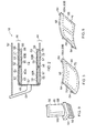
- One of the tiles 58A, 58B is shown more clearly in figure 3 and one of the tiles 60A, 60B is shown more clearly in figure 8 .
- the tiles 58A, 58B, 60A, 60B are shown in the as manufactured condition, e.g. after casting or after forming by direct laser deposition.
- Each tile has a first surface 66 and a second surface 68.
- Each tile has a plurality of studs 64 secured to and extending away from the second surface 68.
- each tile has at least one projection 70, and preferably has a plurality of projections 70, secured to and extending from the first surface 66 in a direction away from the first surface 66 and away from the second surface 68.
- Each projection 70 has a first end 72 adjacent the first surface 66 and a second end 74 remote from the first surface 66.
- Each projection 70 is provided at a position on the respective tile where an effusion aperture, or passage, for coolant is required.
- the tiles 58A, 58B, 60A, 60B are manufactured from a suitable metal or metal alloy for example an iron superalloy, a cobalt superalloy or preferably a nickel superalloy.
- FIGs 4 to 7 show steps in the manufacture of a thermal barrier coated tile 58A.
- figure 4 shows a portion of the tile 58A shown in figure 3 in the as manufactured condition after the first step of casting the tile or forming the tile by direct laser deposition.
- the tile 58A as mentioned previously is formed such that it has at least one projection 70 extending from the first surface 66 of the tile 58A.
- the tile 58A and the at least one projection 70 are formed integrally by casting or alternatively the tile 58A and the at least one projection 70 are formed integrally by direct laser deposition.
- the second end 74 of each projection 70 has a surface 75 which is arranged substantially parallel to the first surface 66 of the tile 58A and in this example each projection 70 has an angled side surface 73. It is preferred that each projection 70 is produced in the tile by producing a recess at the corresponding position in the corresponding surface of the casting mould so that all the projections 70 are produced in the tile by the casting process.
- FIG. 5 shows the portion of the tile 58A after a thermal barrier coating 76 has been deposited onto the first surface 66 of the tile 58A.
- the thermal barrier coating 76 is deposited onto the first surface 66 of the tile 58A by depositing a metallic bond coating 78 on the first surface 66 of the tile 58A and then by depositing a ceramic thermal barrier coating 80 on the metallic bond coating 78. It is to be noted that the thermal barrier coating 76 is deposited onto the first surface 66 of the tile 58A around each of the projections 70 and on the surface 75 at the second end 74 of each projection 70 and also on the angled side surface 73.
- the metallic bond coating 78 may comprise a MCrAlY coating or an aluminide coating, where M is one or more of Ni, Co and Fe.
- the aluminide coating may be a platinum-group metal aluminide, where the platinum-group metal is platinum, palladium, rhodium, iridium or osmium, a silicon aluminide coating, a chromium aluminide, or a combination of one two or more of these.
- the MCrAlY coating may be deposited by plasma spraying, thermal spraying or HVOF.
- the plasma spraying may be vacuum plasma spraying or air plasma spraying.
- the aluminide coating may be deposited by aluminising, by depositing a platinum-group metal and diffusion heat treating and then aluminising, by silicon aluminising, chrome aluminising etc.
- the ceramic thermal barrier coating 80 may comprise stabilised zirconia, for example the ceramic thermal barrier coating 80 may comprise yttria stabilised zirconia. However, other suitable ceramics may be used.
- the ceramic thermal barrier coating may be deposited by plasma spraying, thermal spraying or HVOF.
- the plasma spraying may be vacuum plasma spraying or air plasma spraying.
- Figure 6 shows the portion of the tile 58A after the thermal barrier coating 76 has been removed from the surface 75 at the second end 74 of each projection 70.
- the thermal barrier coating 76 may be removed from the surface 75 at the second end 74 of each projection 70 by machining, e.g. by linishing or automated linishing or other suitable machining process. It is not necessary to remove the thermal barrier coating 76 from the angled side surfaces 73 of the projections 70.
- FIG. 7 shows the portion of the tile 58A after effusion apertures, or passages, 82 have been formed through the tile 58A.
- Each effusion aperture, or passage, 82 extends from the second surface 68 of the tile 58A through the tile 58A and through the respective projection 70 to the surface 75 at the second end 74 of the respective projection 70.
- the tile 58A has a thermal barrier coating 76 on the first surface 66 around each of the projections 70.
- the effusion apertures, or passages, 82 are formed by machining from the surface 75 at the second end 74 of each projection 70 firstly through the respective projection 70 and then the main body of the tile 58A to the second surface 68 of the tile 58A.
- each effusion aperture, or passage, 82 is formed by electro-discharge machining, but other suitable methods may be used.
- each projection 70 may be arranged at a first distance from the first surface 66 of the tile 58A and the thermal barrier coating 76 has a first thickness.
- the first distance may be equal to or greater than the first thickness.
- the second end 74 of each projection 70 is cooled by the coolant, air flowing through the respective effusion aperture 82 and this prevents burning or loss of metal from the second ends 74 of the projections 70.
- Figure 9 shows a turbine blade 90 which comprises a root portion 92, a platform portion 94 and an aerofoil portion 96.
- the aerofoil portion 96 is provided with a thermal barrier coating 98 on its outer surface and a plurality of effusion apertures, or passages, 100 extend through the aerofoil portion 96 of the turbine blade 90.
- the effusion apertures 100 are provided in projections extending from the outer surface of the aerofoil portion 96 of the turbine blade 90 and the thermal barrier coating 98 surrounds all of the projections in a similar manner to that described for the tiles of the combustion chamber with respect to figures 2 to 8 .
- the turbine blade 90 is manufactured from a suitable metal or metal alloy for example an iron superalloy, a cobalt superalloy or preferably a nickel superalloy, e.g. CMSX4, CMSX10 and is produced by casting.
- the turbine blade, or turbine vane may be produced by directional solidification to produce a directionally solidified component, or to produce a single crystal component, or alternatively may be an equiaxed component.
- the projections 70 are tapered at one side, they have an angled side surface 73, to allow the effusion apertures 82 to be arranged at an angle between 90° and 0° to the first surface 66 of the tile 58A.
- the projections 70 have a greater cross-sectional area at the first end 72 than the second end 74.
- projections 70 may be used, for example the projections 70 could be tapered on all sides, the angled side surface 73 extends all around the projection 70, such that they have a greater cross-sectional area at the first end 72 than at the second end 74, e.g. the projections 70 may be conical and decrease in diameter from the first end 72 to the second end 74.
- the effusion apertures have a diameter of at least 0.5mm and up to 1 mm and the projections have a diameter of at least 1 mm and up to 2mm.
- the thermal barrier coating may have a thickness of up to 1 mm, the ceramic thermal barrier coating may have a thickness of up to 0.5mm and the metallic bond coating may have thickness of up to 0.5mm and the projections have a height, a first distance from the surface of the article, of at least the thickness of the thermal barrier coating, e.g. up to 1 mm.
- the present invention provides a thermal barrier coated article, the article having a first surface and a second surface, the article having at least one projection extending from the first surface in a direction away from the first surface and away from the second surface, the projection having a first end adjacent the first surface and a second end remote from the first surface, the article having at least one passage extending from the second surface of the article through the article and through the at least one projection to the second end of the at least one projection and the article having a thermal barrier coating on the first surface around the at least one projection.
- the present invention provides a thermal barrier coated article with a plurality of projections extending from the first surface in a direction away from the first surface and away from the second surface, each projection having a first end adjacent the first surface and a second end remote from the first surface, the article having a plurality of passages extending from the second surface of the article, each passage extending from the second surface of the article through the article and through a respective one of the projections to the second end of the respective projection and the article having a thermal barrier coating on the first surface around each of the projections.
- the article may be a combustor tile, a turbine blade or a turbine vane for a gas turbine engine.
- the advantage of the present invention is that it provides a positive feature, a projection, at each desired aperture position in the article which allows the thermal barrier coating to be removed from the projection thus revealing the metallic article at each desired aperture position. This allows the aperture to be formed through the projection and article by electro-discharge machining due to the formation of an electrically conducting path by the uncovering of the projection.
- the present invention provides an article with a robust thermal barrier coating with no delamination of the thermal barrier coating and un-blocked effusion apertures and the article can be produced in a production worthy cost effective method.
- the dimensions, e.g. diameter, of the projections may be adjusted, made smaller, such that the electro-discharge machining process produces the effusion aperture and also machines away at least a portion of the projection, reduces the height of the projection, to obviate the problem of burning, e.g. the second end of the projection may be located at a first distance from the first surface which is less than the first thickness of the thermal barrier coating.
Applications Claiming Priority (1)
| Application Number | Priority Date | Filing Date | Title |
|---|---|---|---|
| GBGB1205011.8A GB201205011D0 (en) | 2012-03-22 | 2012-03-22 | A thermal barrier coated article and a method of manufacturing a thermal barrier coated article |
Publications (2)
| Publication Number | Publication Date |
|---|---|
| EP2641992A2 true EP2641992A2 (de) | 2013-09-25 |
| EP2641992A3 EP2641992A3 (de) | 2014-05-14 |
Family
ID=46086910
Family Applications (1)
| Application Number | Title | Priority Date | Filing Date |
|---|---|---|---|
| EP13158929.3A Withdrawn EP2641992A3 (de) | 2012-03-22 | 2013-03-13 | Mit einer Wärmesperre beschichteter Artikel und Verfahren zur Herstellung eines mit einer Wärmesperre beschichteten Artikels |
Country Status (4)
| Country | Link |
|---|---|
| US (1) | US20130251941A1 (de) |
| EP (1) | EP2641992A3 (de) |
| JP (1) | JP2013194324A (de) |
| GB (1) | GB201205011D0 (de) |
Cited By (1)
| Publication number | Priority date | Publication date | Assignee | Title |
|---|---|---|---|---|
| US9957811B2 (en) | 2014-10-30 | 2018-05-01 | Rolls-Royce Plc | Cooled component |
Families Citing this family (6)
| Publication number | Priority date | Publication date | Assignee | Title |
|---|---|---|---|---|
| GB201205020D0 (en) * | 2012-03-22 | 2012-05-09 | Rolls Royce Plc | A method of manufacturing a thermal barrier coated article |
| US20140102684A1 (en) * | 2012-10-15 | 2014-04-17 | General Electric Company | Hot gas path component cooling film hole plateau |
| DE102013222863A1 (de) * | 2013-11-11 | 2015-05-13 | Rolls-Royce Deutschland Ltd & Co Kg | Gasturbinenbrennkammer sowie Verfahren zu deren Herstellung |
| DE102014204476A1 (de) | 2014-03-11 | 2015-10-01 | Rolls-Royce Deutschland Ltd & Co Kg | Brennkammer einer Gasturbine |
| DE102014204481A1 (de) | 2014-03-11 | 2015-09-17 | Rolls-Royce Deutschland Ltd & Co Kg | Brennkammer einer Gasturbine |
| EP3342979B1 (de) * | 2016-12-30 | 2020-06-17 | Ansaldo Energia Switzerland AG | Gasturbine mit gekühlten rotorscheiben |
Citations (4)
| Publication number | Priority date | Publication date | Assignee | Title |
|---|---|---|---|---|
| US4743462A (en) * | 1986-07-14 | 1988-05-10 | United Technologies Corporation | Method for preventing closure of cooling holes in hollow, air cooled turbine engine components during application of a plasma spray coating |
| US5902647A (en) * | 1996-12-03 | 1999-05-11 | General Electric Company | Method for protecting passage holes in a metal-based substrate from becoming obstructed, and related compositions |
| EP1859896A1 (de) * | 2006-05-27 | 2007-11-28 | Rolls-Royce plc | Verfahren zum Entfernen von Ablagerungen |
| US20100011775A1 (en) * | 2008-07-17 | 2010-01-21 | Rolls-Royce Plc | Combustion apparatus |
Family Cites Families (2)
| Publication number | Priority date | Publication date | Assignee | Title |
|---|---|---|---|---|
| US6573474B1 (en) * | 2000-10-18 | 2003-06-03 | Chromalloy Gas Turbine Corporation | Process for drilling holes through a thermal barrier coating |
| US20120164376A1 (en) * | 2010-12-23 | 2012-06-28 | General Electric Company | Method of modifying a substrate for passage hole formation therein, and related articles |
-
2012
- 2012-03-22 GB GBGB1205011.8A patent/GB201205011D0/en not_active Ceased
-
2013
- 2013-03-13 US US13/799,501 patent/US20130251941A1/en not_active Abandoned
- 2013-03-13 EP EP13158929.3A patent/EP2641992A3/de not_active Withdrawn
- 2013-03-21 JP JP2013058047A patent/JP2013194324A/ja active Pending
Patent Citations (4)
| Publication number | Priority date | Publication date | Assignee | Title |
|---|---|---|---|---|
| US4743462A (en) * | 1986-07-14 | 1988-05-10 | United Technologies Corporation | Method for preventing closure of cooling holes in hollow, air cooled turbine engine components during application of a plasma spray coating |
| US5902647A (en) * | 1996-12-03 | 1999-05-11 | General Electric Company | Method for protecting passage holes in a metal-based substrate from becoming obstructed, and related compositions |
| EP1859896A1 (de) * | 2006-05-27 | 2007-11-28 | Rolls-Royce plc | Verfahren zum Entfernen von Ablagerungen |
| US20100011775A1 (en) * | 2008-07-17 | 2010-01-21 | Rolls-Royce Plc | Combustion apparatus |
Cited By (1)
| Publication number | Priority date | Publication date | Assignee | Title |
|---|---|---|---|---|
| US9957811B2 (en) | 2014-10-30 | 2018-05-01 | Rolls-Royce Plc | Cooled component |
Also Published As
| Publication number | Publication date |
|---|---|
| US20130251941A1 (en) | 2013-09-26 |
| JP2013194324A (ja) | 2013-09-30 |
| GB201205011D0 (en) | 2012-05-09 |
| EP2641992A3 (de) | 2014-05-14 |
Similar Documents
| Publication | Publication Date | Title |
|---|---|---|
| EP2641993A2 (de) | Verfahren zur Herstellung eines mit einer Wärmesperre beschichteten Artikels | |
| EP2641992A2 (de) | Mit einer Wärmesperre beschichteter Artikel und Verfahren zur Herstellung eines mit einer Wärmesperre beschichteten Artikels | |
| CN106246237B (zh) | 具有近壁冷却特征的热气体路径部件 | |
| US9476306B2 (en) | Components with multi-layered cooling features and methods of manufacture | |
| EP3009744B1 (de) | Auskleidungselement für eine brennkammer und zugehöriges verfahren | |
| US8661826B2 (en) | Combustion apparatus | |
| US6329015B1 (en) | Method for forming shaped holes | |
| US20180015536A1 (en) | Forming cooling passages in combustion turbine superalloy castings | |
| US9897006B2 (en) | Hot gas path component cooling system having a particle collection chamber | |
| US20070292275A1 (en) | Layer system | |
| US20130045106A1 (en) | Angled trench diffuser | |
| US7387814B2 (en) | Process for in situ coating of turbo-machine components | |
| JP4959718B2 (ja) | 流体機械の流路に配置すべき部品および被膜生成のためのスプレイ法 | |
| US20140102684A1 (en) | Hot gas path component cooling film hole plateau | |
| JP2014087924A (ja) | マイクロ冷却される皮膜層を備えた構成要素及び製造方法 | |
| US10408079B2 (en) | Forming cooling passages in thermal barrier coated, combustion turbine superalloy components | |
| CN104797783A (zh) | 在孔周围的改变的表面 | |
| US9862002B2 (en) | Process for producing a layer system | |
| CN105804805A (zh) | 发动机构件和用于发动机构件的方法 | |
| US10843271B2 (en) | Method for manufacturing a turbine shroud for a turbomachine | |
| EP2977678A1 (de) | Auskleidungselement für eine brennkammer | |
| EP2728033B1 (de) | Herstellungsverfahren von komponenten mit mikrogekühlter gemusterter beschichtung | |
| US11156106B2 (en) | Controlling extent of TBC sheet spall | |
| GB2461897A (en) | Shield for preventing coating build up |
Legal Events
| Date | Code | Title | Description |
|---|---|---|---|
| PUAI | Public reference made under article 153(3) epc to a published international application that has entered the european phase |
Free format text: ORIGINAL CODE: 0009012 |
|
| AK | Designated contracting states |
Kind code of ref document: A2 Designated state(s): AL AT BE BG CH CY CZ DE DK EE ES FI FR GB GR HR HU IE IS IT LI LT LU LV MC MK MT NL NO PL PT RO RS SE SI SK SM TR |
|
| AX | Request for extension of the european patent |
Extension state: BA ME |
|
| PUAL | Search report despatched |
Free format text: ORIGINAL CODE: 0009013 |
|
| AK | Designated contracting states |
Kind code of ref document: A3 Designated state(s): AL AT BE BG CH CY CZ DE DK EE ES FI FR GB GR HR HU IE IS IT LI LT LU LV MC MK MT NL NO PL PT RO RS SE SI SK SM TR |
|
| AX | Request for extension of the european patent |
Extension state: BA ME |
|
| RIC1 | Information provided on ipc code assigned before grant |
Ipc: C23C 28/00 20060101ALI20140404BHEP Ipc: F01D 5/28 20060101ALI20140404BHEP Ipc: C23C 4/18 20060101ALI20140404BHEP Ipc: C23C 4/08 20060101ALI20140404BHEP Ipc: C23C 4/10 20060101ALI20140404BHEP Ipc: F01D 5/18 20060101ALI20140404BHEP Ipc: C23C 4/00 20060101AFI20140404BHEP |
|
| 17P | Request for examination filed |
Effective date: 20141029 |
|
| RBV | Designated contracting states (corrected) |
Designated state(s): AL AT BE BG CH CY CZ DE DK EE ES FI FR GB GR HR HU IE IS IT LI LT LU LV MC MK MT NL NO PL PT RO RS SE SI SK SM TR |
|
| RAP1 | Party data changed (applicant data changed or rights of an application transferred) |
Owner name: ROLLS-ROYCE PLC |
|
| 17Q | First examination report despatched |
Effective date: 20150709 |
|
| STAA | Information on the status of an ep patent application or granted ep patent |
Free format text: STATUS: THE APPLICATION IS DEEMED TO BE WITHDRAWN |
|
| 18D | Application deemed to be withdrawn |
Effective date: 20151120 |