EP2641875B1 - Electrolysis device integrating rectifier - Google Patents
Electrolysis device integrating rectifier Download PDFInfo
- Publication number
- EP2641875B1 EP2641875B1 EP11850494.3A EP11850494A EP2641875B1 EP 2641875 B1 EP2641875 B1 EP 2641875B1 EP 11850494 A EP11850494 A EP 11850494A EP 2641875 B1 EP2641875 B1 EP 2641875B1
- Authority
- EP
- European Patent Office
- Prior art keywords
- rectifier
- module
- electrode
- electrolysis device
- bus bar
- Prior art date
- Legal status (The legal status is an assumption and is not a legal conclusion. Google has not performed a legal analysis and makes no representation as to the accuracy of the status listed.)
- Active
Links
Images


Classifications
-
- C—CHEMISTRY; METALLURGY
- C02—TREATMENT OF WATER, WASTE WATER, SEWAGE, OR SLUDGE
- C02F—TREATMENT OF WATER, WASTE WATER, SEWAGE, OR SLUDGE
- C02F1/00—Treatment of water, waste water, or sewage
- C02F1/46—Treatment of water, waste water, or sewage by electrochemical methods
- C02F1/461—Treatment of water, waste water, or sewage by electrochemical methods by electrolysis
- C02F1/46104—Devices therefor; Their operating or servicing
-
- C—CHEMISTRY; METALLURGY
- C25—ELECTROLYTIC OR ELECTROPHORETIC PROCESSES; APPARATUS THEREFOR
- C25B—ELECTROLYTIC OR ELECTROPHORETIC PROCESSES FOR THE PRODUCTION OF COMPOUNDS OR NON-METALS; APPARATUS THEREFOR
- C25B15/00—Operating or servicing cells
- C25B15/02—Process control or regulation
-
- B—PERFORMING OPERATIONS; TRANSPORTING
- B63—SHIPS OR OTHER WATERBORNE VESSELS; RELATED EQUIPMENT
- B63J—AUXILIARIES ON VESSELS
- B63J4/00—Arrangements of installations for treating ballast water, waste water, sewage, sludge, or refuse, or for preventing environmental pollution not otherwise provided for
- B63J4/002—Arrangements of installations for treating ballast water, waste water, sewage, sludge, or refuse, or for preventing environmental pollution not otherwise provided for for treating ballast water
-
- C—CHEMISTRY; METALLURGY
- C02—TREATMENT OF WATER, WASTE WATER, SEWAGE, OR SLUDGE
- C02F—TREATMENT OF WATER, WASTE WATER, SEWAGE, OR SLUDGE
- C02F1/00—Treatment of water, waste water, or sewage
- C02F1/46—Treatment of water, waste water, or sewage by electrochemical methods
- C02F1/461—Treatment of water, waste water, or sewage by electrochemical methods by electrolysis
- C02F1/467—Treatment of water, waste water, or sewage by electrochemical methods by electrolysis by electrochemical disinfection; by electrooxydation or by electroreduction
- C02F1/4672—Treatment of water, waste water, or sewage by electrochemical methods by electrolysis by electrochemical disinfection; by electrooxydation or by electroreduction by electrooxydation
- C02F1/4674—Treatment of water, waste water, or sewage by electrochemical methods by electrolysis by electrochemical disinfection; by electrooxydation or by electroreduction by electrooxydation with halogen or compound of halogens, e.g. chlorine, bromine
-
- C—CHEMISTRY; METALLURGY
- C25—ELECTROLYTIC OR ELECTROPHORETIC PROCESSES; APPARATUS THEREFOR
- C25B—ELECTROLYTIC OR ELECTROPHORETIC PROCESSES FOR THE PRODUCTION OF COMPOUNDS OR NON-METALS; APPARATUS THEREFOR
- C25B9/00—Cells or assemblies of cells; Constructional parts of cells; Assemblies of constructional parts, e.g. electrode-diaphragm assemblies; Process-related cell features
- C25B9/60—Constructional parts of cells
- C25B9/65—Means for supplying current; Electrode connections; Electric inter-cell connections
-
- C—CHEMISTRY; METALLURGY
- C02—TREATMENT OF WATER, WASTE WATER, SEWAGE, OR SLUDGE
- C02F—TREATMENT OF WATER, WASTE WATER, SEWAGE, OR SLUDGE
- C02F2103/00—Nature of the water, waste water, sewage or sludge to be treated
- C02F2103/008—Originating from marine vessels, ships and boats, e.g. bilge water or ballast water
-
- C—CHEMISTRY; METALLURGY
- C02—TREATMENT OF WATER, WASTE WATER, SEWAGE, OR SLUDGE
- C02F—TREATMENT OF WATER, WASTE WATER, SEWAGE, OR SLUDGE
- C02F2201/00—Apparatus for treatment of water, waste water or sewage
- C02F2201/002—Construction details of the apparatus
- C02F2201/007—Modular design
-
- C—CHEMISTRY; METALLURGY
- C02—TREATMENT OF WATER, WASTE WATER, SEWAGE, OR SLUDGE
- C02F—TREATMENT OF WATER, WASTE WATER, SEWAGE, OR SLUDGE
- C02F2201/00—Apparatus for treatment of water, waste water or sewage
- C02F2201/46—Apparatus for electrochemical processes
- C02F2201/461—Electrolysis apparatus
- C02F2201/46105—Details relating to the electrolytic devices
- C02F2201/4612—Controlling or monitoring
- C02F2201/46125—Electrical variables
- C02F2201/4613—Inversing polarity
-
- C—CHEMISTRY; METALLURGY
- C02—TREATMENT OF WATER, WASTE WATER, SEWAGE, OR SLUDGE
- C02F—TREATMENT OF WATER, WASTE WATER, SEWAGE, OR SLUDGE
- C02F2303/00—Specific treatment goals
- C02F2303/14—Maintenance of water treatment installations
Definitions
- the present invention relates to an electrolysis device for treating ballast water, waste water, or sewage, or for generating sterilized water.
- ballast water or impurity-containing water are treated by electrolysis, i.e., using an electrolytic reaction which is caused when water passes through a electrolytic cell of an electrolysis device and the water comes into contact with electrode plates inside the electrolytic cell.
- the conventional electrolysis device for electrolyzing water is connected to a rectifier, which is installed at a certain distance from the electrolysis device, via a cable and a bus bar.
- the electrolysis device and the rectifier are separately installed, a space saving efficiency is low and there is a restriction in where the electrolysis device can be installed.
- the apparatus In the case of using an electrolysis device that is used in a large space, for example, on land, the apparatus is relatively free from restriction in terms of the installation space, and compensation for the power loss, which is likely to occur across the cable, is relatively easy to achieve. Accordingly, the apparatus is used without being restricted in terms of the installation place and power loss.
- impurities which were not filtered out when water is introduced into the electrolytic cell, or various kinds of salts that are byproducts of an electrolysis reaction, are likely to stick to electrodes.
- the impurities sticking to the electrodes cause damage to the electrodes and become a factor of lowering efficiency of sterilizing polluted water. Accordingly, polarities of the electrodes need to be changed to remove the sticking impurities.
- the polarities of the electrodes in the conventional electrolysis device are determined and changed by a circuit in the rectifier.
- the present invention has been made keeping in mind the above problems occurring in the related art, and is intended to provide an electrolysis device with a rectifier in which the electrolysis device and the rectifier are integrally formed to eliminate the cost of cable and power loss occurring across the cable.
- the present invention also serves to provide an electrolysis device with a rectifier in which the electrolysis device and the rectifier are integrally formed to efficiently fit into a small space, for example, on a ship.
- the present invention also serves to provide an electrolysis device with a rectifier that achieves switching between polarities of electrodes in a simple manner by using a bus bar.
- the present invention provides an electrolysis device with a rectifier which treats water, the electrolysis device including: an electrolytic cell with an introduction hole and a discharge hole formed at opposing ends, respectively; a joint panel with a first surface joined to a first side surface of the electrolytic cell; an electrode module including a housing, a plurality of electrodes provided inside the housing, and an auxiliary panel having a first surface which is joined to a second surface of the joint panel, the auxiliary panel having a first end which passes through the first side surface of the electrolytic cell and the joint panel and is installed in the electrolytic cell and a second end which perpendicularly protrudes outward from an external periphery of a second end of the housing, over the entire length of the external periphery; a rectifier module having a first side surface located outside the second end of the housing of the electrode module and a second side surface from which an electrode protrudes; an L-shaped panel having two surfaces joined to the second surface of the joint panel and any one
- the bus bar may include: a first bus bar having a first end which is in close contact with the electrode located at the second end of the housing of the electrode module and a second end which protrudes from the second side surface of the rectifier module; and a second bus bar having a first end connected to the second end of the first bus bar and a second end connected to the electrode of the rectifier module.
- the electrolysis device may further include a bus cover joined to the second side surface of the rectifier module in a manner of surrounding the electrode of the rectifier module and the bus bar protruding from the second side surface of the rectifier module, and a heat-sinking plate joined to the first side surface of the rectifier module.
- a protrusion bar and a rail may be correspondingly formed on an upper surface and a lower surface of the rectifier module, respectively, or vice versa, to guide horizontal movement of the rectifier module.
- the electrolysis device may further include through-holes formed in the first side surface of the electrolytic cell and the joint panel, respectively so that electrode module may be inserted into the electrolytic cell, a handle which protrudes from any one side surface of the rectifier module, and an LED display window which is formed in any one side surface of the rectifier module to display any one operation state among a normal operation state, a malfunction state, and a no-power state of the rectifier module.
- switching of the polarities may be achieved by using the bus bar.
- the electrolysis device since an electrolysis device and a rectifier are unified into a body, it is possible to eliminate a cost of cable and to prevent power loss occurring across the cable.
- the electrolysis device according to the present invention allows space saving and easy switching of polarities of electrodes. Furthermore, the electrolysis device is easy to use.
- the electrolysis device may be advantageous in terms of designing a waterproof and explosion-proof structure.
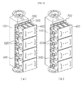
- FIGS. 1 to 3 are perspective views illustrating an electrolysis device with a rectifier according to one embodiment of the present invention.
- FIG. 1 is an enlarged perspective view and
- FIG. 2 illustrates a connection relation between upper and lower rectifier modules 400.
- FIGS. 3(a) and 3(b) illustrate an operation in which switching of polarities is achieved by using a bus bar.
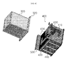
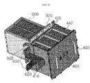
- FIGS. 4 and 5 are perspective views illustrating each component of an electrode module 300 and the rectifier module 400 in the electrolysis device with a rectifier according to the present invention, and a connection relation between the electrode module 300 and the connection module 400.
- FIG. 4 is a perspective view of the electrode module 300 and the rectifier module 400 viewed from the bottom
- FIG. 5 is a perspective view of the electrode module 300 and the rectifier module 400 viewed from the top.
- the electrolysis device with a rectifier is an water treatment apparatus and includes an electrolytic cell 100, a joint panel 200, the electrode module 300, the rectifier module 400, and a bus bar.
- the electrolytic cell 100 has an introduction hole and a discharge hole at opposing ends, respectively.
- the joint panel 200 has a first surface joined to a first side surface of the electrolytic cell 100.
- the electrode module 300 includes a housing, a plurality of electrodes provided inside the housing, and an auxiliary panel 320.
- the auxiliary panel 320 has a first end which passes through the first side surface of the electrolytic cell 100 and the joint panel 200 and is installed in the electrolytic cell 100, and a second end which extends over the entire length of an external periphery of a second end of the housing of the electrode module 300 and perpendicularly protrudes from the external periphery.
- a first surface of the auxiliary panel 320 is joined to a second surface of the joint panel 200.
- the rectifier module 400 has a first side surface located outside the second end of the electrode module 300 and a second side surface from which an electrode 410 protrudes.
- the L-shaped panel 500 has two surfaces joined to the second surface of the joint panel 200 and any one side surface of the rectifier module 400, respectively.
- the bus bar connects the electrode module 300 and the rectifier module 400 to each other.
- the electrolytic cell 100 is a casing in which electrolysis is performed.
- the electrolytic cell 100 has the introduction hole through which water as a treatment target is introduced and the discharge hole through which sterilized water, which has undergone water treatment, is discharged to the outside.
- the first surface of the joint panel 200 is joined to the first side surface of the electrolytic cell 100 by welding or bolt-screwing, and serves as a coupling means for joining the rectifier module 400 to the electrolytic cell 100.
- the electrode module 300 includes the auxiliary panel 320.
- the first end passes through the first side surface of the electrolytic cell 100 and the joint panel 200 and is installed inside the electrolytic cell 100, and the second end of the auxiliary panel 320 extends along the external periphery of the second end of the housing of the electrode module 300 and protrudes outward from the external periphery.
- the first surface of the auxiliary panel 320 is joined to the second surface of the joint panel 200.
- the electrode module 300 encloses the plurality of electrodes.
- the auxiliary panel 320 protrudes outward from the external periphery of the second end of the housing of the electrode module 300.
- the auxiliary panel 320 may be formed by attaching a separate member to the external periphery of the housing of the electrode module 300.
- the first side surface of the electrolytic cell 100 and the joint panel 200 may have a through hole to allow the electrode module 300 to be inserted into the electrolytic cell 100 therethrough.
- auxiliary panel 320 and the surface of the joint panel 200 which face each other are joined to each other using a coupling means such as a bolt.
- a coupling means such as a bolt.
- the electrode module 300 is joined to the electrolytic cell 100.
- a gasket of an elastic material such as rubber may be installed between the auxiliary panel 320 and the joint panel 200 to provide hermetic sealing, so that leakage of water in the electrolytic cell 100 may be prevented.
- a plurality of electrode plates serving as an anode and a plurality of electrode plates serving as a cathode are arrayed in parallel to each other.
- the plurality of electrodes are provided in the electrolytic cell to sterilize water by causing oxidation/reduction reactions.
- the rectifier module 400 is installed in such a manner that one side surface of the rectifier module 400 is disposed near the external surface at the second end of the electrode module 300 and electrodes 410 of the anode and cathode protrude from one of the other side surfaces of the rectifier module 400.
- one or more rectifier modules 400 may be joined to one surface of the electrolytic cell 100.
- rectifier module 400 In regard to the rectifier module 400, according to the preferred embodiment, four rectifier modules 400, each weighting 35 Kg or less and having performance of 13 V and 1300 A, may be attached to one surface of the electrolytic cell 100 weighting 220 kg.
- the rectifier module 400 is joined to the electrolytic cell 100 using the L-shaped panel 500, respective side surfaces of which are joined to the second surface of the joint panel 200 and any one side surface of the rectifier module by coupling means such as a bolt.
- An elastic member such as a gasket is installed between the L-shaped panel 500 and the rectifier module 400 and between the L-shaped panel 500 and the electrode module 300 in order to remove gaps and to provide hermetic sealing between the electrolytic cell 19 and the rectifier module 400.
- two L-shaped panels 500 may be symmetrically provided on left and right sides, respectively.
- a C-shaped notch may be formed at an end portion of the L-shaped panel 500 to allow the bus bar to pass through.
- a heat-sinking plate 430 may be provided on one side surface of the rectifier module 400.
- the heat-sinking plate 430 dissipates heat from the rectifier module 400. So, there is no need to install an additional cooling pipe in the rectifier.
- the heat-dissipating plate 430 is disposed so as to face the electrode module 300.
- Protrusion bars 440 are formed on either upper surface or lower surface of the rectifier module 400 and rails 442 are formed on the other surface of the upper surface and the lower surface of the rectifier module 440.
- Each protrusion bar 440 and each rail 442 are formed at corresponding positions in order to guide horizontal movement of the rectifier module 440.
- the electrolytic cell 100 and the rectifier module 400 can be easily disassembled and reassembled.
- the protrusion bars 440 and the rails 442 are linearly formed to extend across the upper and lower surfaces of the rectifier module 400, respectively.
- handles 450 may be provided on any one side surface of the rectifier module 400.
- An LED display window 460 for displaying an operation state (for example, a normal operation state, a malfunction state, and a no-power state) of the rectifier module 400 may be further provided on any one surface of the rectifier module 400.
- the positions of the handles 450 are aligned with the positions of the protrusion bars 440 and the rails 442, and the handles 450 may be configured to have sufficient strength in terms of the weight of the rectifier module 400.
- the bus bar is a conductor which allows transmission of positive and negative currents and connects electrodes of the electrode module 300 and electrodes of the rectifier module 400.
- the electrodes of the same polarity are connected to each other. That is, a positive electrode of the electrode module 300 is connected to a positive electrode of the rectifier module 400 and a negative electrode of the electrode module 300 is connected to a negative electrode of the rectifier module 400.
- the bus bar may include a first bus bar 600 in which a first end of the first bus bar 600 is in close contact with the electrode which is located at the second end of the electrode module 300 and a second end of the first bus bar 600 protrudes from the second side surface of the rectifier module 400, and a second bus bar 620 in which a first end of the second bus bar 620 is connected to the second end of the first bus bar 600 and a second end of the second bus bar 620 is connected to the electrode 410 of the rectifier module 400.
- the electrode located at the second end of the electrode module 300 may be an electrode connected to the plurality of electrodes provided inside the electrode module 300.
- the first bus bar 600 may be orthogonally bent to form an L-shape and the second bus bar 620 may be orthogonally bent two times to form a Z-shape.
- a bus cover 420 may be joined to the second side surface of the rectifier module 400 in a manner to surround the electrode 410 of the rectifier module 400 and the bus bar protruding from the second side surface of the rectifier module 400.
- the bus cover 420 is illustrated in FIG. 1 and may be jointed to the rectifier module 400 by using a bolt.
- Polarity switching in the electrolysis device according to the invention is performed by using the bus bar.
- the bus cover 420 is removed first, and then connection of the ends of the second bus bar 620 is changed in such a manner that the second end of the second bus bar 620 is connected to the electrode 410 of the rectifier module 400. In this way, the polarity switching is achieved.
Landscapes
- Chemical & Material Sciences (AREA)
- Engineering & Computer Science (AREA)
- Chemical Kinetics & Catalysis (AREA)
- Electrochemistry (AREA)
- Organic Chemistry (AREA)
- Environmental & Geological Engineering (AREA)
- Materials Engineering (AREA)
- Metallurgy (AREA)
- General Chemical & Material Sciences (AREA)
- Water Supply & Treatment (AREA)
- Hydrology & Water Resources (AREA)
- Life Sciences & Earth Sciences (AREA)
- General Health & Medical Sciences (AREA)
- Combustion & Propulsion (AREA)
- Mechanical Engineering (AREA)
- Ocean & Marine Engineering (AREA)
- Toxicology (AREA)
- Public Health (AREA)
- Health & Medical Sciences (AREA)
- Automation & Control Theory (AREA)
- Water Treatment By Electricity Or Magnetism (AREA)
- Electrolytic Production Of Non-Metals, Compounds, Apparatuses Therefor (AREA)
Description
- The present invention relates to an electrolysis device for treating ballast water, waste water, or sewage, or for generating sterilized water.
- Conventionally, ballast water or impurity-containing water are treated by electrolysis, i.e., using an electrolytic reaction which is caused when water passes through a electrolytic cell of an electrolysis device and the water comes into contact with electrode plates inside the electrolytic cell.
- The conventional electrolysis device for electrolyzing water is connected to a rectifier, which is installed at a certain distance from the electrolysis device, via a cable and a bus bar.
- When a cable is used as a connection medium for connecting the electrolysis device and the rectifier, as the cable increases in length, electrical resistance also increases. This results in considerable power loss in the cable.
- Furthermore, since the electrolysis device and the rectifier are separately installed, a space saving efficiency is low and there is a restriction in where the electrolysis device can be installed.
- In the case of using an electrolysis device that is used in a large space, for example, on land, the apparatus is relatively free from restriction in terms of the installation space, and compensation for the power loss, which is likely to occur across the cable, is relatively easy to achieve. Accordingly, the apparatus is used without being restricted in terms of the installation place and power loss.
- On the other hand, in the case of an electrolysis device for use in a small space, for example, on a ship, since available space and power are limited, the space and power required for the apparatus need to be efficiently used.
- In another aspect, in the electrolysis device for electrolyzing water, impurities which were not filtered out when water is introduced into the electrolytic cell, or various kinds of salts that are byproducts of an electrolysis reaction, are likely to stick to electrodes.
- The impurities sticking to the electrodes cause damage to the electrodes and become a factor of lowering efficiency of sterilizing polluted water. Accordingly, polarities of the electrodes need to be changed to remove the sticking impurities.
- The polarities of the electrodes in the conventional electrolysis device are determined and changed by a circuit in the rectifier.
- The document
WO2008/038853 gives an example of an electrolysis device with rectifier known from the prior art. - Accordingly, the present invention has been made keeping in mind the above problems occurring in the related art, and is intended to provide an electrolysis device with a rectifier in which the electrolysis device and the rectifier are integrally formed to eliminate the cost of cable and power loss occurring across the cable.
- The present invention also serves to provide an electrolysis device with a rectifier in which the electrolysis device and the rectifier are integrally formed to efficiently fit into a small space, for example, on a ship.
- The present invention also serves to provide an electrolysis device with a rectifier that achieves switching between polarities of electrodes in a simple manner by using a bus bar.
- In order to solve the above problems, in an aspect, the present invention provides an electrolysis device with a rectifier which treats water, the electrolysis device including: an electrolytic cell with an introduction hole and a discharge hole formed at opposing ends, respectively; a joint panel with a first surface joined to a first side surface of the electrolytic cell; an electrode module including a housing, a plurality of electrodes provided inside the housing, and an auxiliary panel having a first surface which is joined to a second surface of the joint panel, the auxiliary panel having a first end which passes through the first side surface of the electrolytic cell and the joint panel and is installed in the electrolytic cell and a second end which perpendicularly protrudes outward from an external periphery of a second end of the housing, over the entire length of the external periphery; a rectifier module having a first side surface located outside the second end of the housing of the electrode module and a second side surface from which an electrode protrudes; an L-shaped panel having two surfaces joined to the second surface of the joint panel and any one side surface of the rectifier module, respectively; and a bus bar that connects the electrode of the electrode module to the electrode of the rectifier module.
- The bus bar may include: a first bus bar having a first end which is in close contact with the electrode located at the second end of the housing of the electrode module and a second end which protrudes from the second side surface of the rectifier module; and a second bus bar having a first end connected to the second end of the first bus bar and a second end connected to the electrode of the rectifier module.
- The electrolysis device may further include a bus cover joined to the second side surface of the rectifier module in a manner of surrounding the electrode of the rectifier module and the bus bar protruding from the second side surface of the rectifier module, and a heat-sinking plate joined to the first side surface of the rectifier module.
- A protrusion bar and a rail may be correspondingly formed on an upper surface and a lower surface of the rectifier module, respectively, or vice versa, to guide horizontal movement of the rectifier module.
- The electrolysis device may further include through-holes formed in the first side surface of the electrolytic cell and the joint panel, respectively so that electrode module may be inserted into the electrolytic cell, a handle which protrudes from any one side surface of the rectifier module, and an LED display window which is formed in any one side surface of the rectifier module to display any one operation state among a normal operation state, a malfunction state, and a no-power state of the rectifier module.
- In the electrolysis device, switching of the polarities may be achieved by using the bus bar.
- According to the electrolysis device according to the present invention, since an electrolysis device and a rectifier are unified into a body, it is possible to eliminate a cost of cable and to prevent power loss occurring across the cable.
- The electrolysis device according to the present invention allows space saving and easy switching of polarities of electrodes. Furthermore, the electrolysis device is easy to use.
- Moreover, since an electrolytic cell and the rectifier are configured as a closed structure, the electrolysis device may be advantageous in terms of designing a waterproof and explosion-proof structure.
-
-
FIGS. 1 to 3 are perspective views illustrating an electrolysis device with a rectifier according to an embodiment of the present invention; and -
FIGS. 4 to 5 are perspective views illustrating the structure of each component of an electrode module and a rectifier module in the electrolysis device with a rectifier according to the embodiment of the present invention and a connection relation between the electrode module and the rectifier module. - Hereinbelow, the present invention will be described in detail with reference to embodiments and the accompanying drawings.
-
FIGS. 1 to 3 are perspective views illustrating an electrolysis device with a rectifier according to one embodiment of the present invention.FIG. 1 is an enlarged perspective view andFIG. 2 illustrates a connection relation between upper andlower rectifier modules 400.FIGS. 3(a) and 3(b) illustrate an operation in which switching of polarities is achieved by using a bus bar. -
FIGS. 4 and5 are perspective views illustrating each component of anelectrode module 300 and therectifier module 400 in the electrolysis device with a rectifier according to the present invention, and a connection relation between theelectrode module 300 and theconnection module 400.FIG. 4 is a perspective view of theelectrode module 300 and therectifier module 400 viewed from the bottom, andFIG. 5 is a perspective view of theelectrode module 300 and therectifier module 400 viewed from the top. - As illustrated in
FIGS. 1 to 3 , the electrolysis device with a rectifier according to the present invention is an water treatment apparatus and includes anelectrolytic cell 100, ajoint panel 200, theelectrode module 300, therectifier module 400, and a bus bar. Theelectrolytic cell 100 has an introduction hole and a discharge hole at opposing ends, respectively. Thejoint panel 200 has a first surface joined to a first side surface of theelectrolytic cell 100. Theelectrode module 300 includes a housing, a plurality of electrodes provided inside the housing, and anauxiliary panel 320. Theauxiliary panel 320 has a first end which passes through the first side surface of theelectrolytic cell 100 and thejoint panel 200 and is installed in theelectrolytic cell 100, and a second end which extends over the entire length of an external periphery of a second end of the housing of theelectrode module 300 and perpendicularly protrudes from the external periphery. A first surface of theauxiliary panel 320 is joined to a second surface of thejoint panel 200. Therectifier module 400 has a first side surface located outside the second end of theelectrode module 300 and a second side surface from which anelectrode 410 protrudes. The L-shaped panel 500 has two surfaces joined to the second surface of thejoint panel 200 and any one side surface of therectifier module 400, respectively. The bus bar connects theelectrode module 300 and therectifier module 400 to each other. - The
electrolytic cell 100 is a casing in which electrolysis is performed. Theelectrolytic cell 100 has the introduction hole through which water as a treatment target is introduced and the discharge hole through which sterilized water, which has undergone water treatment, is discharged to the outside. - The first surface of the
joint panel 200 is joined to the first side surface of theelectrolytic cell 100 by welding or bolt-screwing, and serves as a coupling means for joining therectifier module 400 to theelectrolytic cell 100. - The
electrode module 300 includes theauxiliary panel 320. In regard to theauxiliary panel 320, the first end passes through the first side surface of theelectrolytic cell 100 and thejoint panel 200 and is installed inside theelectrolytic cell 100, and the second end of theauxiliary panel 320 extends along the external periphery of the second end of the housing of theelectrode module 300 and protrudes outward from the external periphery. The first surface of theauxiliary panel 320 is joined to the second surface of thejoint panel 200. Theelectrode module 300 encloses the plurality of electrodes. - As shown in
FIG. 4 , theauxiliary panel 320 protrudes outward from the external periphery of the second end of the housing of theelectrode module 300. Theauxiliary panel 320 may be formed by attaching a separate member to the external periphery of the housing of theelectrode module 300. - In addition, although not illustrated, the first side surface of the
electrolytic cell 100 and thejoint panel 200 may have a through hole to allow theelectrode module 300 to be inserted into theelectrolytic cell 100 therethrough. - The surface of the
auxiliary panel 320 and the surface of thejoint panel 200 which face each other are joined to each other using a coupling means such as a bolt. In this way, theelectrode module 300 is joined to theelectrolytic cell 100. In this case, a gasket of an elastic material such as rubber may be installed between theauxiliary panel 320 and thejoint panel 200 to provide hermetic sealing, so that leakage of water in theelectrolytic cell 100 may be prevented. - As an example of the electrodes, a plurality of electrode plates serving as an anode and a plurality of electrode plates serving as a cathode are arrayed in parallel to each other. The plurality of electrodes are provided in the electrolytic cell to sterilize water by causing oxidation/reduction reactions.
- The
rectifier module 400 is installed in such a manner that one side surface of therectifier module 400 is disposed near the external surface at the second end of theelectrode module 300 andelectrodes 410 of the anode and cathode protrude from one of the other side surfaces of therectifier module 400. - In the present invention, one or
more rectifier modules 400 may be joined to one surface of theelectrolytic cell 100. - In regard to the
rectifier module 400, according to the preferred embodiment, fourrectifier modules 400, each weighting 35 Kg or less and having performance of 13 V and 1300 A, may be attached to one surface of theelectrolytic cell 100 weighting 220 kg. - The
rectifier module 400 is joined to theelectrolytic cell 100 using the L-shapedpanel 500, respective side surfaces of which are joined to the second surface of thejoint panel 200 and any one side surface of the rectifier module by coupling means such as a bolt. - An elastic member such as a gasket is installed between the L-shaped
panel 500 and therectifier module 400 and between the L-shapedpanel 500 and theelectrode module 300 in order to remove gaps and to provide hermetic sealing between the electrolytic cell 19 and therectifier module 400. - As illustrated in
FIG. 1 , two L-shapedpanels 500 may be symmetrically provided on left and right sides, respectively. A C-shaped notch may be formed at an end portion of the L-shapedpanel 500 to allow the bus bar to pass through. - A heat-sinking
plate 430 may be provided on one side surface of therectifier module 400. - The heat-sinking
plate 430 dissipates heat from therectifier module 400. So, there is no need to install an additional cooling pipe in the rectifier. - In
FIG. 1 , the heat-dissipatingplate 430 is disposed so as to face theelectrode module 300. - Protrusion bars 440 are formed on either upper surface or lower surface of the
rectifier module 400 andrails 442 are formed on the other surface of the upper surface and the lower surface of therectifier module 440. Eachprotrusion bar 440 and eachrail 442 are formed at corresponding positions in order to guide horizontal movement of therectifier module 440. - When installing and maintaining the
rectifier module 400, theelectrolytic cell 100 and therectifier module 400 can be easily disassembled and reassembled. - As illustrated in
FIGS. 4 and5 , the protrusion bars 440 and therails 442 are linearly formed to extend across the upper and lower surfaces of therectifier module 400, respectively. - In order to achieve easy installation and maintenance of the
rectifier module 400, handles 450 may be provided on any one side surface of therectifier module 400. AnLED display window 460 for displaying an operation state (for example, a normal operation state, a malfunction state, and a no-power state) of therectifier module 400 may be further provided on any one surface of therectifier module 400. - For the sake of convenience of handling the
rectifier module 400, the positions of thehandles 450 are aligned with the positions of the protrusion bars 440 and therails 442, and thehandles 450 may be configured to have sufficient strength in terms of the weight of therectifier module 400. - The bus bar is a conductor which allows transmission of positive and negative currents and connects electrodes of the
electrode module 300 and electrodes of therectifier module 400. - When connecting the electrodes of the
electrode module 300 and the electrodes of therectifier module 400, the electrodes of the same polarity are connected to each other. That is, a positive electrode of theelectrode module 300 is connected to a positive electrode of therectifier module 400 and a negative electrode of theelectrode module 300 is connected to a negative electrode of therectifier module 400. - The bus bar may include a
first bus bar 600 in which a first end of thefirst bus bar 600 is in close contact with the electrode which is located at the second end of theelectrode module 300 and a second end of thefirst bus bar 600 protrudes from the second side surface of therectifier module 400, and asecond bus bar 620 in which a first end of thesecond bus bar 620 is connected to the second end of thefirst bus bar 600 and a second end of thesecond bus bar 620 is connected to theelectrode 410 of therectifier module 400. - The electrode located at the second end of the
electrode module 300 may be an electrode connected to the plurality of electrodes provided inside theelectrode module 300. - As illustrated in
FIG. 4 , thefirst bus bar 600 may be orthogonally bent to form an L-shape and thesecond bus bar 620 may be orthogonally bent two times to form a Z-shape. - Since an electric current of a high voltage flows through the
electrode 410 of therectifier module 400 and the bus bar, abus cover 420 may be joined to the second side surface of therectifier module 400 in a manner to surround theelectrode 410 of therectifier module 400 and the bus bar protruding from the second side surface of therectifier module 400. - The
bus cover 420 is illustrated inFIG. 1 and may be jointed to therectifier module 400 by using a bolt. - Polarity switching in the electrolysis device according to the invention is performed by using the bus bar.
- As illustrated in
FIGS. 3(a) and 3(b) , thebus cover 420 is removed first, and then connection of the ends of thesecond bus bar 620 is changed in such a manner that the second end of thesecond bus bar 620 is connected to theelectrode 410 of therectifier module 400. In this way, the polarity switching is achieved. - Although the embodiments of the present invention have been disclosed for illustrative purposes, those skilled in the art will appreciate that various modifications, additions and substitutions are possible, without departing from the scope of the invention as disclosed in the accompanying claims.
| 100: | Electrolytic cell | 200: | Joint panel |
| 300: | Electrode module | 320: | Auxiliary panel |
| 400: | Rectifier module | 410: | Electrode |
| 420: | Bus cover | 430: | Heat-sinking plate |
| 440: | Protruding bar | 442: | Rail |
| 450: | Handle | 460: | LED display window |
| 500: | L-shaped panel | 600: | First bus bar |
| 620: | Second bus bar |
Claims (10)
- An electrolysis device with a rectifier for treating water, comprising:an electrolytic cell (100) with an introduction hole and a discharge hole formed at opposing ends, respectively;a joint panel (200) with a first surface joined to a first side surface of the electrolytic cell (100);an electrode module (300) including a housing, a plurality of electrodes provided inside the housing, and an auxiliary panel (320) having a first surface which is joined to a second surface of the joint panel (200), the auxiliary panel (320) having a first end which passes through the first side surface of the electrolytic cell (100) and the joint panel (200) and is inserted into and installed in the electrolytic cell (100) and a second end which perpendicularly protrudes outward from an external periphery of a second end of the housing, over the entire length of the external periphery;a rectifier module (400) having a first side surface located outside the second end of the housing of the electrode module (300) and a second side surface from which an electrode (410) protrudes;an L-shaped panel (500) having two surfaces joined to the second surface of the joint panel (200) and any one side surface of the rectifier module (400), respectively; anda bus bar that connects the electrode of the electrode module (300) to the electrode (410) of the rectifier module (400) .
- The electrolysis device with a rectifier according to claim 1, wherein the bus bar includes:a first bus bar (600) having a first end which is in close contact with the electrode located at the second end of the housing of the electrode module (300) and a second end which protrudes from the second side surface of the rectifier module (400); anda second bus bar (620) having a first end connected to the second end of the first bus bar (600) and a second end connected to the electrode (410) of the rectifier module (400).
- The electrolysis device with a rectifier according to claim 2, wherein the first bus bar (600) has a letter "L" shape and the second bus bar (620) has a letter "Z" shape.
- The electrolysis device with a rectifier according to claim 1, further comprising a bus cover (420) joined to the second side surface of the rectifier module (400) in a manner of surrounding the electrode (410) of the rectifier module (400) and the bus bar protruding from the second side surface of the rectifier module (400).
- The electrolysis device with a rectifier according to claim 1, further comprising a heat-sinking plate (430) joined with one side surface of the rectifier module (400).
- The electrolysis device with a rectifier according to claim 1, wherein a protrusion bar (440) and a rail (442) are correspondingly formed on an upper surface and a lower surface of the rectifier module (400), respectively or vice versa, thereby guiding horizontal movement of the rectifier module (400).
- The electrolysis device with a rectifier according to claim 1, wherein the first side surface of the electrolytic cell (100) and the joint panel (200) have a through-hole which allows the electrode module (300) to be inserted into the electrolytic cell (100).
- The electrolysis device with a rectifier according to claim 1, further comprising a handle (450) protruding from any one side surface of the rectifier module (400).
- The electrolysis device with a rectifier according to claim 1, further comprising an LED display window (460) provided in any one side surface of the rectifier module (400), the LED display window (460) displaying any one operation state among a normal operation state, a malfunction state, and a no-power state.
- The electrolysis device with a rectifier according to any one of claims 1 to 9, wherein switching of polarities of the electrodes of the electrolysis device is achieved by using the bus bar.
Applications Claiming Priority (2)
| Application Number | Priority Date | Filing Date | Title |
|---|---|---|---|
| KR1020100132335A KR101087571B1 (en) | 2010-12-22 | 2010-12-22 | Rectifier integrated electrolysis device |
| PCT/KR2011/009112 WO2012086934A2 (en) | 2010-12-22 | 2011-11-28 | Electrolysis device integrating rectifier |
Publications (3)
| Publication Number | Publication Date |
|---|---|
| EP2641875A2 EP2641875A2 (en) | 2013-09-25 |
| EP2641875A4 EP2641875A4 (en) | 2014-10-01 |
| EP2641875B1 true EP2641875B1 (en) | 2016-03-02 |
Family
ID=45505378
Family Applications (1)
| Application Number | Title | Priority Date | Filing Date |
|---|---|---|---|
| EP11850494.3A Active EP2641875B1 (en) | 2010-12-22 | 2011-11-28 | Electrolysis device integrating rectifier |
Country Status (7)
| Country | Link |
|---|---|
| US (1) | US9394187B2 (en) |
| EP (1) | EP2641875B1 (en) |
| JP (1) | JP5934248B2 (en) |
| KR (1) | KR101087571B1 (en) |
| CN (1) | CN103402924B (en) |
| SG (1) | SG191335A1 (en) |
| WO (1) | WO2012086934A2 (en) |
Cited By (1)
| Publication number | Priority date | Publication date | Assignee | Title |
|---|---|---|---|---|
| WO2025170962A1 (en) * | 2024-02-06 | 2025-08-14 | PowerTech Water, Inc. | Cartridge with integrated power supply for electrochemical water treatment |
Families Citing this family (14)
| Publication number | Priority date | Publication date | Assignee | Title |
|---|---|---|---|---|
| KR101345784B1 (en) * | 2012-03-14 | 2014-01-07 | (주) 테크로스 | Including diffuser integrated rectifier electrolysis |
| KR101450522B1 (en) | 2012-05-15 | 2014-10-14 | (주) 테크로스 | Electrolysis apparatus with rectifier |
| KR101431597B1 (en) * | 2012-05-22 | 2014-08-22 | (주) 테크로스 | Electrode wiring sturcture of electrolysis device and electrode defect detecting method using thereof |
| DE102014000518A1 (en) * | 2014-01-15 | 2015-07-16 | Etogas Gmbh | Arrangement for supplying an electrolyzer with direct current and installation for carrying out an electrolysis |
| FI128729B (en) * | 2015-12-22 | 2020-11-13 | Outotec Finland Oy | ELECTRODE MODULE, ELECTROCHEMICAL REACTOR, AND WATER TREATMENT DEVICE |
| WO2018045355A1 (en) * | 2016-09-02 | 2018-03-08 | Bioionix,Inc. | Configuration for electrochemical water treatment |
| JP2018094486A (en) * | 2016-12-12 | 2018-06-21 | ケイティー マリーン カンパニー,リミテッド | Electrolysis device for ballast water |
| CN106976955B (en) * | 2017-04-26 | 2020-12-11 | 中国科学院生态环境研究中心 | Electrode, monopolar chamber bioelectrochemical device and method for adjusting its hydraulic flow |
| US10239771B2 (en) * | 2017-07-21 | 2019-03-26 | Water Vision, Inc. | Electrocoagulation unit |
| KR101924017B1 (en) * | 2017-11-23 | 2019-02-22 | (주)케이티마린 | Electrolysis apparatus for ballast water of vessel |
| KR101989879B1 (en) * | 2018-02-26 | 2019-06-17 | (주)케이티마린 | Explosion proof ballast water management apparatus with rectifier |
| KR102082986B1 (en) * | 2018-12-13 | 2020-03-02 | (주) 테크로스 | Electrolysis apparatus |
| DE102023206268A1 (en) | 2023-07-03 | 2025-01-09 | Robert Bosch Gesellschaft mit beschränkter Haftung | Electrolysis system and method for operating such an electrolysis system |
| KR102765820B1 (en) * | 2023-12-26 | 2025-02-07 | 김원모 | Wastewater treatment system with electrode module mounted chamber |
Family Cites Families (16)
| Publication number | Priority date | Publication date | Assignee | Title |
|---|---|---|---|---|
| KR100236542B1 (en) * | 1997-05-23 | 2000-01-15 | 박영배 | Apparatus for the purification of sewage and waste water using electrolytic units |
| JP2001174431A (en) | 1999-12-21 | 2001-06-29 | Matsushita Electric Ind Co Ltd | Apparatus and method for measuring residual chlorine concentration in acidic liquid |
| JP2002345991A (en) * | 2001-05-23 | 2002-12-03 | Kenji Suzuki | PCB processing apparatus and PCB processing method by electrolysis |
| TW547489U (en) | 2001-09-14 | 2003-08-11 | Shihlin Electric & Engineering | Hydrogen oxygen generation device with insertion type electrolytic tank |
| KR200287583Y1 (en) | 2002-05-30 | 2002-08-30 | 주식회사 이온 | A electrolyzed ion water producing device |
| JP4010453B2 (en) | 2003-01-29 | 2007-11-21 | シルバー精工株式会社 | Reduced hydrogen water generator |
| JP3099101U (en) | 2003-07-07 | 2004-03-25 | 林 士涵 | Structure of mixed gas generator |
| JP3570429B1 (en) | 2003-08-08 | 2004-09-29 | 株式会社クボタマシン | Oxygen and hydrogen gas generator and method of assembling the same |
| JP2005177603A (en) | 2003-12-19 | 2005-07-07 | Taisei Kogyo Kk | Metal ion producing apparatus |
| ES1062811Y (en) | 2006-04-20 | 2006-11-01 | I D Electroquimica S L | AUTOMATIC WATER TREATMENT DEVICE BY ELECTROLYSIS, WITH PH AND REDOX CONTROL |
| KR100802365B1 (en) | 2006-09-29 | 2008-02-13 | 박대원 | AC-WE filter |
| JP4696255B2 (en) | 2007-11-12 | 2011-06-08 | 株式会社富永製作所 | Sterilization method for dental facilities, toilet bowl sterilization method, and electrolyzed water supply system for dental facilities |
| KR20100008548U (en) * | 2009-02-19 | 2010-08-27 | (주) 테크로스 | Electrode Module |
| KR20110061819A (en) | 2009-12-02 | 2011-06-10 | 주식회사 케이엔티 | Electrolyzer with removable electrode for ballast water treatment of ships |
| KR100981585B1 (en) * | 2010-03-08 | 2010-09-10 | 문정아 | Structure for multi type electrolytic cell |
| US20110303533A1 (en) * | 2010-06-09 | 2011-12-15 | Wen Shing Shyu | Electrolyzer device having cooling structure |
-
2010
- 2010-12-22 KR KR1020100132335A patent/KR101087571B1/en active Active
-
2011
- 2011-11-28 WO PCT/KR2011/009112 patent/WO2012086934A2/en not_active Ceased
- 2011-11-28 SG SG2013048806A patent/SG191335A1/en unknown
- 2011-11-28 CN CN201180062174.5A patent/CN103402924B/en active Active
- 2011-11-28 US US13/997,570 patent/US9394187B2/en active Active
- 2011-11-28 JP JP2013546001A patent/JP5934248B2/en active Active
- 2011-11-28 EP EP11850494.3A patent/EP2641875B1/en active Active
Cited By (1)
| Publication number | Priority date | Publication date | Assignee | Title |
|---|---|---|---|---|
| WO2025170962A1 (en) * | 2024-02-06 | 2025-08-14 | PowerTech Water, Inc. | Cartridge with integrated power supply for electrochemical water treatment |
Also Published As
| Publication number | Publication date |
|---|---|
| KR101087571B1 (en) | 2011-12-23 |
| CN103402924B (en) | 2015-06-10 |
| WO2012086934A3 (en) | 2012-09-07 |
| CN103402924A (en) | 2013-11-20 |
| US20140042019A1 (en) | 2014-02-13 |
| JP5934248B2 (en) | 2016-06-15 |
| WO2012086934A2 (en) | 2012-06-28 |
| EP2641875A4 (en) | 2014-10-01 |
| SG191335A1 (en) | 2013-08-30 |
| US9394187B2 (en) | 2016-07-19 |
| JP2014506294A (en) | 2014-03-13 |
| EP2641875A2 (en) | 2013-09-25 |
Similar Documents
| Publication | Publication Date | Title |
|---|---|---|
| US9394187B2 (en) | Electrolysis device integrating rectifier | |
| KR100918958B1 (en) | Hydrogen-oxygen mixed gas generator | |
| US20130107436A1 (en) | Power supply unit and power supply system for servers | |
| ATE532401T1 (en) | HIGH PERFORMANCE MODULAR DRIVE BLOCK COOLED WITH A VAPORIZABLE DIELECTRIC LIQUID | |
| WO2010138007A3 (en) | An enclosure for secondary distribution modular switchgears | |
| US20140162476A1 (en) | Junction box, solar cell and method for installing bus bar in junction box | |
| KR102160807B1 (en) | Anode module for zinc nickel electroplating apparatus and electroplating method using the same | |
| CN114658148A (en) | Curtain wall unit, photovoltaic curtain wall and building | |
| TW201303562A (en) | Power supply system | |
| JP5906266B2 (en) | Electrolyzed water generator | |
| CN103546018B (en) | A kind of power cell and manufacture method thereof | |
| CN205099425U (en) | A plate electrode device for electro -fenton processing difficult degradation organic waste water | |
| UA124032C2 (en) | Four-quadrant power module | |
| KR101345784B1 (en) | Including diffuser integrated rectifier electrolysis | |
| CN202931178U (en) | A low stray inductance power module using hard insulating boards | |
| CN215637033U (en) | Multifunctional double-rail track | |
| KR20240002535A (en) | High-concentration wastewater treatment device that treats pollutants with strong oxidizing power using plasma | |
| CN212894047U (en) | A electrolytic device for reducing COD in sewage | |
| CN111807330B (en) | An air source plate ozone generator | |
| CN220964107U (en) | American case becomes top cap | |
| CN224084625U (en) | A hydroxyl generator and a cleaning basin | |
| CN208174554U (en) | A kind of high-frequency direct-current power module | |
| CN215626965U (en) | Metal ion generator for circulating water | |
| CN215772042U (en) | Shore power variable frequency power supply cabinet mounting structure | |
| CN214782176U (en) | Novel hypochlorous acid antiseptic solution takes place device |
Legal Events
| Date | Code | Title | Description |
|---|---|---|---|
| PUAI | Public reference made under article 153(3) epc to a published international application that has entered the european phase |
Free format text: ORIGINAL CODE: 0009012 |
|
| 17P | Request for examination filed |
Effective date: 20130621 |
|
| AK | Designated contracting states |
Kind code of ref document: A2 Designated state(s): AL AT BE BG CH CY CZ DE DK EE ES FI FR GB GR HR HU IE IS IT LI LT LU LV MC MK MT NL NO PL PT RO RS SE SI SK SM TR |
|
| DAX | Request for extension of the european patent (deleted) | ||
| A4 | Supplementary search report drawn up and despatched |
Effective date: 20140903 |
|
| RIC1 | Information provided on ipc code assigned before grant |
Ipc: B63J 4/00 20060101ALI20140828BHEP Ipc: C25B 9/00 20060101ALI20140828BHEP Ipc: C02F 1/461 20060101AFI20140828BHEP |
|
| RIN1 | Information on inventor provided before grant (corrected) |
Inventor name: KIM, SUNG TEA Inventor name: LEE, HAI DON Inventor name: PARK, YONG SEOK Inventor name: LEE, GWANG HO Inventor name: KIM, YOUNG MIN Inventor name: LEE, IK HWAN Inventor name: PARK, KYU WON |
|
| RIN1 | Information on inventor provided before grant (corrected) |
Inventor name: LEE, GWANG HO Inventor name: LEE, IK HWAN Inventor name: KIM, YOUNG MIN Inventor name: KIM, SUNG TEA Inventor name: PARK, KYU WON Inventor name: PARK, YONG SEOK Inventor name: LEE, HAI DON |
|
| RIN1 | Information on inventor provided before grant (corrected) |
Inventor name: LEE, IK HWAN Inventor name: LEE, HAI DON Inventor name: KIM, SUNG TEA Inventor name: LEE, GWANG HO Inventor name: PARK, KYU WON Inventor name: KIM, YOUNG MIN Inventor name: PARK, YONG SEOK |
|
| GRAP | Despatch of communication of intention to grant a patent |
Free format text: ORIGINAL CODE: EPIDOSNIGR1 |
|
| INTG | Intention to grant announced |
Effective date: 20150813 |
|
| GRAS | Grant fee paid |
Free format text: ORIGINAL CODE: EPIDOSNIGR3 |
|
| GRAA | (expected) grant |
Free format text: ORIGINAL CODE: 0009210 |
|
| AK | Designated contracting states |
Kind code of ref document: B1 Designated state(s): AL AT BE BG CH CY CZ DE DK EE ES FI FR GB GR HR HU IE IS IT LI LT LU LV MC MK MT NL NO PL PT RO RS SE SI SK SM TR |
|
| REG | Reference to a national code |
Ref country code: GB Ref legal event code: FG4D |
|
| REG | Reference to a national code |
Ref country code: AT Ref legal event code: REF Ref document number: 777905 Country of ref document: AT Kind code of ref document: T Effective date: 20160315 Ref country code: CH Ref legal event code: EP |
|
| REG | Reference to a national code |
Ref country code: IE Ref legal event code: FG4D |
|
| REG | Reference to a national code |
Ref country code: DE Ref legal event code: R096 Ref document number: 602011023751 Country of ref document: DE |
|
| REG | Reference to a national code |
Ref country code: NL Ref legal event code: FP |
|
| REG | Reference to a national code |
Ref country code: NO Ref legal event code: T2 Effective date: 20160302 Ref country code: LT Ref legal event code: MG4D |
|
| REG | Reference to a national code |
Ref country code: AT Ref legal event code: MK05 Ref document number: 777905 Country of ref document: AT Kind code of ref document: T Effective date: 20160302 |
|
| PG25 | Lapsed in a contracting state [announced via postgrant information from national office to epo] |
Ref country code: HR Free format text: LAPSE BECAUSE OF FAILURE TO SUBMIT A TRANSLATION OF THE DESCRIPTION OR TO PAY THE FEE WITHIN THE PRESCRIBED TIME-LIMIT Effective date: 20160302 Ref country code: ES Free format text: LAPSE BECAUSE OF FAILURE TO SUBMIT A TRANSLATION OF THE DESCRIPTION OR TO PAY THE FEE WITHIN THE PRESCRIBED TIME-LIMIT Effective date: 20160302 Ref country code: FI Free format text: LAPSE BECAUSE OF FAILURE TO SUBMIT A TRANSLATION OF THE DESCRIPTION OR TO PAY THE FEE WITHIN THE PRESCRIBED TIME-LIMIT Effective date: 20160302 |
|
| PG25 | Lapsed in a contracting state [announced via postgrant information from national office to epo] |
Ref country code: LT Free format text: LAPSE BECAUSE OF FAILURE TO SUBMIT A TRANSLATION OF THE DESCRIPTION OR TO PAY THE FEE WITHIN THE PRESCRIBED TIME-LIMIT Effective date: 20160302 Ref country code: SE Free format text: LAPSE BECAUSE OF FAILURE TO SUBMIT A TRANSLATION OF THE DESCRIPTION OR TO PAY THE FEE WITHIN THE PRESCRIBED TIME-LIMIT Effective date: 20160302 Ref country code: RS Free format text: LAPSE BECAUSE OF FAILURE TO SUBMIT A TRANSLATION OF THE DESCRIPTION OR TO PAY THE FEE WITHIN THE PRESCRIBED TIME-LIMIT Effective date: 20160302 Ref country code: LV Free format text: LAPSE BECAUSE OF FAILURE TO SUBMIT A TRANSLATION OF THE DESCRIPTION OR TO PAY THE FEE WITHIN THE PRESCRIBED TIME-LIMIT Effective date: 20160302 Ref country code: AT Free format text: LAPSE BECAUSE OF FAILURE TO SUBMIT A TRANSLATION OF THE DESCRIPTION OR TO PAY THE FEE WITHIN THE PRESCRIBED TIME-LIMIT Effective date: 20160302 Ref country code: PL Free format text: LAPSE BECAUSE OF FAILURE TO SUBMIT A TRANSLATION OF THE DESCRIPTION OR TO PAY THE FEE WITHIN THE PRESCRIBED TIME-LIMIT Effective date: 20160302 |
|
| REG | Reference to a national code |
Ref country code: GR Ref legal event code: EP Ref document number: 20160401033 Country of ref document: GR Effective date: 20160628 |
|
| PG25 | Lapsed in a contracting state [announced via postgrant information from national office to epo] |
Ref country code: IS Free format text: LAPSE BECAUSE OF FAILURE TO SUBMIT A TRANSLATION OF THE DESCRIPTION OR TO PAY THE FEE WITHIN THE PRESCRIBED TIME-LIMIT Effective date: 20160702 Ref country code: EE Free format text: LAPSE BECAUSE OF FAILURE TO SUBMIT A TRANSLATION OF THE DESCRIPTION OR TO PAY THE FEE WITHIN THE PRESCRIBED TIME-LIMIT Effective date: 20160302 |
|
| PG25 | Lapsed in a contracting state [announced via postgrant information from national office to epo] |
Ref country code: SK Free format text: LAPSE BECAUSE OF FAILURE TO SUBMIT A TRANSLATION OF THE DESCRIPTION OR TO PAY THE FEE WITHIN THE PRESCRIBED TIME-LIMIT Effective date: 20160302 Ref country code: SM Free format text: LAPSE BECAUSE OF FAILURE TO SUBMIT A TRANSLATION OF THE DESCRIPTION OR TO PAY THE FEE WITHIN THE PRESCRIBED TIME-LIMIT Effective date: 20160302 Ref country code: PT Free format text: LAPSE BECAUSE OF FAILURE TO SUBMIT A TRANSLATION OF THE DESCRIPTION OR TO PAY THE FEE WITHIN THE PRESCRIBED TIME-LIMIT Effective date: 20160704 Ref country code: RO Free format text: LAPSE BECAUSE OF FAILURE TO SUBMIT A TRANSLATION OF THE DESCRIPTION OR TO PAY THE FEE WITHIN THE PRESCRIBED TIME-LIMIT Effective date: 20160302 Ref country code: CZ Free format text: LAPSE BECAUSE OF FAILURE TO SUBMIT A TRANSLATION OF THE DESCRIPTION OR TO PAY THE FEE WITHIN THE PRESCRIBED TIME-LIMIT Effective date: 20160302 |
|
| REG | Reference to a national code |
Ref country code: FR Ref legal event code: PLFP Year of fee payment: 6 |
|
| REG | Reference to a national code |
Ref country code: DE Ref legal event code: R097 Ref document number: 602011023751 Country of ref document: DE |
|
| PG25 | Lapsed in a contracting state [announced via postgrant information from national office to epo] |
Ref country code: BE Free format text: LAPSE BECAUSE OF FAILURE TO SUBMIT A TRANSLATION OF THE DESCRIPTION OR TO PAY THE FEE WITHIN THE PRESCRIBED TIME-LIMIT Effective date: 20160302 Ref country code: IT Free format text: LAPSE BECAUSE OF FAILURE TO SUBMIT A TRANSLATION OF THE DESCRIPTION OR TO PAY THE FEE WITHIN THE PRESCRIBED TIME-LIMIT Effective date: 20160302 |
|
| PLBE | No opposition filed within time limit |
Free format text: ORIGINAL CODE: 0009261 |
|
| STAA | Information on the status of an ep patent application or granted ep patent |
Free format text: STATUS: NO OPPOSITION FILED WITHIN TIME LIMIT |
|
| PG25 | Lapsed in a contracting state [announced via postgrant information from national office to epo] |
Ref country code: DK Free format text: LAPSE BECAUSE OF FAILURE TO SUBMIT A TRANSLATION OF THE DESCRIPTION OR TO PAY THE FEE WITHIN THE PRESCRIBED TIME-LIMIT Effective date: 20160302 |
|
| 26N | No opposition filed |
Effective date: 20161205 |
|
| PG25 | Lapsed in a contracting state [announced via postgrant information from national office to epo] |
Ref country code: BG Free format text: LAPSE BECAUSE OF FAILURE TO SUBMIT A TRANSLATION OF THE DESCRIPTION OR TO PAY THE FEE WITHIN THE PRESCRIBED TIME-LIMIT Effective date: 20160602 Ref country code: SI Free format text: LAPSE BECAUSE OF FAILURE TO SUBMIT A TRANSLATION OF THE DESCRIPTION OR TO PAY THE FEE WITHIN THE PRESCRIBED TIME-LIMIT Effective date: 20160302 |
|
| REG | Reference to a national code |
Ref country code: CH Ref legal event code: PL |
|
| PG25 | Lapsed in a contracting state [announced via postgrant information from national office to epo] |
Ref country code: CH Free format text: LAPSE BECAUSE OF NON-PAYMENT OF DUE FEES Effective date: 20161130 Ref country code: LI Free format text: LAPSE BECAUSE OF NON-PAYMENT OF DUE FEES Effective date: 20161130 |
|
| REG | Reference to a national code |
Ref country code: IE Ref legal event code: MM4A |
|
| PG25 | Lapsed in a contracting state [announced via postgrant information from national office to epo] |
Ref country code: LU Free format text: LAPSE BECAUSE OF NON-PAYMENT OF DUE FEES Effective date: 20161130 |
|
| REG | Reference to a national code |
Ref country code: FR Ref legal event code: PLFP Year of fee payment: 7 |
|
| PG25 | Lapsed in a contracting state [announced via postgrant information from national office to epo] |
Ref country code: IE Free format text: LAPSE BECAUSE OF NON-PAYMENT OF DUE FEES Effective date: 20161128 |
|
| PG25 | Lapsed in a contracting state [announced via postgrant information from national office to epo] |
Ref country code: CY Free format text: LAPSE BECAUSE OF FAILURE TO SUBMIT A TRANSLATION OF THE DESCRIPTION OR TO PAY THE FEE WITHIN THE PRESCRIBED TIME-LIMIT Effective date: 20160302 Ref country code: HU Free format text: LAPSE BECAUSE OF FAILURE TO SUBMIT A TRANSLATION OF THE DESCRIPTION OR TO PAY THE FEE WITHIN THE PRESCRIBED TIME-LIMIT; INVALID AB INITIO Effective date: 20111128 |
|
| PG25 | Lapsed in a contracting state [announced via postgrant information from national office to epo] |
Ref country code: MK Free format text: LAPSE BECAUSE OF FAILURE TO SUBMIT A TRANSLATION OF THE DESCRIPTION OR TO PAY THE FEE WITHIN THE PRESCRIBED TIME-LIMIT Effective date: 20160302 Ref country code: MC Free format text: LAPSE BECAUSE OF FAILURE TO SUBMIT A TRANSLATION OF THE DESCRIPTION OR TO PAY THE FEE WITHIN THE PRESCRIBED TIME-LIMIT Effective date: 20160302 |
|
| PG25 | Lapsed in a contracting state [announced via postgrant information from national office to epo] |
Ref country code: MT Free format text: LAPSE BECAUSE OF NON-PAYMENT OF DUE FEES Effective date: 20161128 |
|
| PG25 | Lapsed in a contracting state [announced via postgrant information from national office to epo] |
Ref country code: AL Free format text: LAPSE BECAUSE OF FAILURE TO SUBMIT A TRANSLATION OF THE DESCRIPTION OR TO PAY THE FEE WITHIN THE PRESCRIBED TIME-LIMIT Effective date: 20160302 Ref country code: TR Free format text: LAPSE BECAUSE OF FAILURE TO SUBMIT A TRANSLATION OF THE DESCRIPTION OR TO PAY THE FEE WITHIN THE PRESCRIBED TIME-LIMIT Effective date: 20160302 |
|
| REG | Reference to a national code |
Ref country code: NO Ref legal event code: CREP Representative=s name: PLOUGMANN VINGTOFT, POSTBOKS 1003 SENTRUM, 0104 Ref country code: NO Ref legal event code: CHAD Owner name: TECHCROSS INC., KR |
|
| REG | Reference to a national code |
Ref country code: DE Ref legal event code: R081 Ref document number: 602011023751 Country of ref document: DE Owner name: TECHCROSS INC., KR Free format text: FORMER OWNER: TECHCROSS CO., LTD., SEOUL, KR |
|
| REG | Reference to a national code |
Ref country code: GB Ref legal event code: 732E Free format text: REGISTERED BETWEEN 20221103 AND 20221109 |
|
| REG | Reference to a national code |
Ref country code: NL Ref legal event code: PD Owner name: TECHCROSS INC.; KR Free format text: DETAILS ASSIGNMENT: CHANGE OF OWNER(S), ASSIGNMENT; FORMER OWNER NAME: TECHCROSS HOLDINGS INC. Effective date: 20240115 Ref country code: NL Ref legal event code: HC Owner name: TECHCROSS HOLDINGS INC.; KR Free format text: DETAILS ASSIGNMENT: CHANGE OF OWNER(S), CHANGE OF OWNER(S) NAME; FORMER OWNER NAME: TECHCROSS CO., LTD. Effective date: 20240115 |
|
| PGFP | Annual fee paid to national office [announced via postgrant information from national office to epo] |
Ref country code: NL Payment date: 20251128 Year of fee payment: 15 |
|
| PGFP | Annual fee paid to national office [announced via postgrant information from national office to epo] |
Ref country code: GB Payment date: 20251226 Year of fee payment: 15 |
|
| PGFP | Annual fee paid to national office [announced via postgrant information from national office to epo] |
Ref country code: NO Payment date: 20251202 Year of fee payment: 15 |
|
| PGFP | Annual fee paid to national office [announced via postgrant information from national office to epo] |
Ref country code: FR Payment date: 20251114 Year of fee payment: 15 |
|
| PGFP | Annual fee paid to national office [announced via postgrant information from national office to epo] |
Ref country code: GR Payment date: 20251128 Year of fee payment: 15 |
|
| PGFP | Annual fee paid to national office [announced via postgrant information from national office to epo] |
Ref country code: DE Payment date: 20251231 Year of fee payment: 15 |