EP2641769A1 - Diesel particulate filter mounting structure for industrial vehicle - Google Patents
Diesel particulate filter mounting structure for industrial vehicle Download PDFInfo
- Publication number
- EP2641769A1 EP2641769A1 EP11842338.3A EP11842338A EP2641769A1 EP 2641769 A1 EP2641769 A1 EP 2641769A1 EP 11842338 A EP11842338 A EP 11842338A EP 2641769 A1 EP2641769 A1 EP 2641769A1
- Authority
- EP
- European Patent Office
- Prior art keywords
- particulate filter
- diesel particulate
- mounting structure
- counter weight
- opening
- Prior art date
- Legal status (The legal status is an assumption and is not a legal conclusion. Google has not performed a legal analysis and makes no representation as to the accuracy of the status listed.)
- Withdrawn
Links
Images


Classifications
-
- B—PERFORMING OPERATIONS; TRANSPORTING
- B60—VEHICLES IN GENERAL
- B60K—ARRANGEMENT OR MOUNTING OF PROPULSION UNITS OR OF TRANSMISSIONS IN VEHICLES; ARRANGEMENT OR MOUNTING OF PLURAL DIVERSE PRIME-MOVERS IN VEHICLES; AUXILIARY DRIVES FOR VEHICLES; INSTRUMENTATION OR DASHBOARDS FOR VEHICLES; ARRANGEMENTS IN CONNECTION WITH COOLING, AIR INTAKE, GAS EXHAUST OR FUEL SUPPLY OF PROPULSION UNITS IN VEHICLES
- B60K13/00—Arrangement in connection with combustion air intake or gas exhaust of propulsion units
- B60K13/04—Arrangement in connection with combustion air intake or gas exhaust of propulsion units concerning exhaust
-
- B—PERFORMING OPERATIONS; TRANSPORTING
- B66—HOISTING; LIFTING; HAULING
- B66F—HOISTING, LIFTING, HAULING OR PUSHING, NOT OTHERWISE PROVIDED FOR, e.g. DEVICES WHICH APPLY A LIFTING OR PUSHING FORCE DIRECTLY TO THE SURFACE OF A LOAD
- B66F9/00—Devices for lifting or lowering bulky or heavy goods for loading or unloading purposes
- B66F9/06—Devices for lifting or lowering bulky or heavy goods for loading or unloading purposes movable, with their loads, on wheels or the like, e.g. fork-lift trucks
- B66F9/075—Constructional features or details
- B66F9/07554—Counterweights
-
- B—PERFORMING OPERATIONS; TRANSPORTING
- B66—HOISTING; LIFTING; HAULING
- B66F—HOISTING, LIFTING, HAULING OR PUSHING, NOT OTHERWISE PROVIDED FOR, e.g. DEVICES WHICH APPLY A LIFTING OR PUSHING FORCE DIRECTLY TO THE SURFACE OF A LOAD
- B66F9/00—Devices for lifting or lowering bulky or heavy goods for loading or unloading purposes
- B66F9/06—Devices for lifting or lowering bulky or heavy goods for loading or unloading purposes movable, with their loads, on wheels or the like, e.g. fork-lift trucks
- B66F9/075—Constructional features or details
- B66F9/07572—Propulsion arrangements
-
- E—FIXED CONSTRUCTIONS
- E02—HYDRAULIC ENGINEERING; FOUNDATIONS; SOIL SHIFTING
- E02F—DREDGING; SOIL-SHIFTING
- E02F9/00—Component parts of dredgers or soil-shifting machines, not restricted to one of the kinds covered by groups E02F3/00 - E02F7/00
- E02F9/08—Superstructures; Supports for superstructures
- E02F9/0858—Arrangement of component parts installed on superstructures not otherwise provided for, e.g. electric components, fenders, air-conditioning units
- E02F9/0866—Engine compartment, e.g. heat exchangers, exhaust filters, cooling devices, silencers, mufflers, position of hydraulic pumps in the engine compartment
-
- F—MECHANICAL ENGINEERING; LIGHTING; HEATING; WEAPONS; BLASTING
- F01—MACHINES OR ENGINES IN GENERAL; ENGINE PLANTS IN GENERAL; STEAM ENGINES
- F01N—GAS-FLOW SILENCERS OR EXHAUST APPARATUS FOR MACHINES OR ENGINES IN GENERAL; GAS-FLOW SILENCERS OR EXHAUST APPARATUS FOR INTERNAL-COMBUSTION ENGINES
- F01N13/00—Exhaust or silencing apparatus characterised by constructional features
- F01N13/18—Construction facilitating manufacture, assembly, or disassembly
- F01N13/1805—Fixing exhaust manifolds, exhaust pipes or pipe sections to each other, to engine or to vehicle body
-
- B—PERFORMING OPERATIONS; TRANSPORTING
- B60—VEHICLES IN GENERAL
- B60K—ARRANGEMENT OR MOUNTING OF PROPULSION UNITS OR OF TRANSMISSIONS IN VEHICLES; ARRANGEMENT OR MOUNTING OF PLURAL DIVERSE PRIME-MOVERS IN VEHICLES; AUXILIARY DRIVES FOR VEHICLES; INSTRUMENTATION OR DASHBOARDS FOR VEHICLES; ARRANGEMENTS IN CONNECTION WITH COOLING, AIR INTAKE, GAS EXHAUST OR FUEL SUPPLY OF PROPULSION UNITS IN VEHICLES
- B60K11/00—Arrangement in connection with cooling of propulsion units
- B60K11/02—Arrangement in connection with cooling of propulsion units with liquid cooling
- B60K11/04—Arrangement or mounting of radiators, radiator shutters, or radiator blinds
-
- B—PERFORMING OPERATIONS; TRANSPORTING
- B60—VEHICLES IN GENERAL
- B60Y—INDEXING SCHEME RELATING TO ASPECTS CROSS-CUTTING VEHICLE TECHNOLOGY
- B60Y2200/00—Type of vehicle
- B60Y2200/10—Road Vehicles
- B60Y2200/15—Fork lift trucks, Industrial trucks
-
- B—PERFORMING OPERATIONS; TRANSPORTING
- B60—VEHICLES IN GENERAL
- B60Y—INDEXING SCHEME RELATING TO ASPECTS CROSS-CUTTING VEHICLE TECHNOLOGY
- B60Y2200/00—Type of vehicle
- B60Y2200/40—Special vehicles
- B60Y2200/41—Construction vehicles, e.g. graders, excavators
-
- B—PERFORMING OPERATIONS; TRANSPORTING
- B60—VEHICLES IN GENERAL
- B60Y—INDEXING SCHEME RELATING TO ASPECTS CROSS-CUTTING VEHICLE TECHNOLOGY
- B60Y2200/00—Type of vehicle
- B60Y2200/40—Special vehicles
- B60Y2200/41—Construction vehicles, e.g. graders, excavators
- B60Y2200/412—Excavators
-
- B—PERFORMING OPERATIONS; TRANSPORTING
- B60—VEHICLES IN GENERAL
- B60Y—INDEXING SCHEME RELATING TO ASPECTS CROSS-CUTTING VEHICLE TECHNOLOGY
- B60Y2200/00—Type of vehicle
- B60Y2200/40—Special vehicles
- B60Y2200/41—Construction vehicles, e.g. graders, excavators
- B60Y2200/415—Wheel loaders
-
- B—PERFORMING OPERATIONS; TRANSPORTING
- B60—VEHICLES IN GENERAL
- B60Y—INDEXING SCHEME RELATING TO ASPECTS CROSS-CUTTING VEHICLE TECHNOLOGY
- B60Y2304/00—Optimising design; Manufacturing; Testing
- B60Y2304/07—Facilitating assembling or mounting
- B60Y2304/074—Facilitating assembling or mounting by improved accessibility
-
- F—MECHANICAL ENGINEERING; LIGHTING; HEATING; WEAPONS; BLASTING
- F01—MACHINES OR ENGINES IN GENERAL; ENGINE PLANTS IN GENERAL; STEAM ENGINES
- F01N—GAS-FLOW SILENCERS OR EXHAUST APPARATUS FOR MACHINES OR ENGINES IN GENERAL; GAS-FLOW SILENCERS OR EXHAUST APPARATUS FOR INTERNAL-COMBUSTION ENGINES
- F01N2590/00—Exhaust or silencing apparatus adapted to particular use, e.g. for military applications, airplanes, submarines
- F01N2590/08—Exhaust or silencing apparatus adapted to particular use, e.g. for military applications, airplanes, submarines for heavy duty applications, e.g. trucks, buses, tractors, locomotives
Definitions
- the present invention relates generally to diesel particulate filter mounting structure for industrial vehicles with counter weights such as forklifts, shovel loaders and the like, and more particularly to improvements of such a mounting structure.
- An industrial vehicle such as a forklift and a shovel loader has a handling device for cargo handling operation at a front side part of the vehicle and a counter weight for retaining valance of the vehicle during cargo handling operation at a back side part of the vehicle.
- the counter weight is generally fixedly attached to a body frame with a bolt or the like.
- a muffler for discharging exhaust gas from an engine is housed in the counter weight.
- the muffler normally does not need regular maintenance.
- the prior art structure requires detachment of the heavy counter weight from the body frame at the time of maintenance, which is very bothersome.
- Japanese Patent Application Publication Nos. 1989-317879 and 1992-148797 disclose structure in which the counter weight is rotatably supported at the body frame horizontally or back and forth.
- soot that is accumulated in the diesel particulate filters during use of them can be burned using exhaust gas of high temperature.
- ash accumulated in the diesel particulate filters since it cannot be burned even using exhaust gas of high temperature, a removing process using another device is required after the diesel particulate filters are detached from the vehicles.
- Japanese Utility Model Registration Application Publication No. 1993-89823 and Japanese Patent Application Publication No. 2004-218570 disclose structure in which the diesel particulate filter is detachably fitted to the body frame.
- the diesel particulate filter is not described relevantly to the counter weight for the industrial vehicle.
- the publications disclose nothing from the standpoint of the way on how to install the diesel particulate filter detachably relative to the counter weight for the industrial vehicle.
- the present invention has been made in view of these circumstances and its object is to provide mounting structure that allows for easy attachment and detachment of a diesel particulate filter without detaching or removing a counter weight.
- the present invention is directed to improving maintenance of the diesel particulate filter.
- a mounting structure is for installing a diesel particulate filter to remove particulate matter included in emission of an engine of an industrial vehicle.
- the industrial vehicle includes a vehicle body, a handling device provided in front of the vehicle body, and a counter weight provided at the rear of the vehicle body and housing a diesel particulate filter.
- the diesel particulate filter is detachably fitted to a frame that is provided at the rear of the vehicle body.
- the counter weight has an opening formed therethrough, which is sized so that the diesel particulate filter can pass through the opening vertically.
- a maintenance worker when performing maintenance of the diesel particulate filter, a maintenance worker has only to take the diesel particulate filter out of the vehicle utilizing the opening (i.e. through hole) formed vertically through the counter weight. Also, when putting the diesel particulate filter back into the vehicle, the maintenance worker has only to utilize the opening (i.e. through hole) formed vertically through the counter weight.
- the diesel particulate filter may be fastened with a screw at the frame.
- the diesel particulate filter is provided detachably at the frame through the screw.
- the diesel particulate filter may be provided at the frame via a rubber vibration insulator.
- the counter weight may have another opening formed in and extending longitudinally through a rear surface thereof and the screw may face another opening. In this case, screwing and unscrewing of the screw can be performed through another opening formed in the rear surface of the counter weight, thus improving working property at the time of maintenance.
- the diesel particulate filter may be laterally biased toward either one of opposite sides at the rear of the vehicle body.
- the diesel particulate filter in the event that an engine exhaust pipe is laterally biased toward either one of opposite sides of the vehicle body, the diesel particulate filter can be connected to such an engine exhaust pipe via the shortest route.
- the opening may be disposed laterally centrally at the counter weight.
- the opening may have a cover detachably fitted thereto for closing the opening, and the cover may have a muffler inserted thereinto and connected to the diesel particulate filter.
- the cover may have a muffler inserted thereinto and connected to the diesel particulate filter.
- the cover may have a rib formed on an inner surface of the cover for introducing air flow.
- air flow can be rectified to be introduced toward the rear of the diesel particulate filter.
- the cover may act as a rear shroud for introducing engine cooling air flow toward the rear of the vehicle.
- engine cooling air flow can be introduced toward the rear of the vehicle.
- the industrial vehicle may be a forklift or a shovel loader.
- a maintenance worker when performing maintenance of the diesel particulate filter, a maintenance worker has only to take the diesel particulate filter out of the vehicle using the opening formed vertically through the counter weight and also when putting the diesel particulate filter back into the vehicle, the maintenance worker has only to use the opening formed vertically through the counter weight.
- FIGS. 1 to 7 illustrate a diesel particulate filter mounting structure according to an embodiment of the present invention.
- a forklift or a forklift truck is taken as an example of an industrial vehicle.
- a forklift 1 includes a vehicle body 2, a handling device 3 such as a fork provided in front of the vehicle body 2, and a counter weight 4 provided at the rear of the vehicle body 2.
- the counter weight 4 has, as shown in FIG. 2 , an opening 4a that is formed in and extends through an upper panel 4A of the counter weight 4 and that is centrally disposed in a lateral direction (i.e. in the left to right direction of FIG. 2 ) of the upper panel 4A.
- the opening 4a has a cover 5 detachably fitted thereto via a screw or the like for closing the opening 4a.
- the cover 5 has a through hole 5a formed therein.
- a muffler 40 is inserted into the through hole 5a and extends upwardly.
- a diesel particulate filter 6 in the counter weight 4 is for collecting and removing particulate matter (PM) included in emission of a diesel engine.
- An exhaust gas intake side of the diesel particulate filter 6 is connected to an exhaust pipe 60 extending from an engine 10 and an exhaust gas outlet side of the diesel particulate filter 6 is connected to an end of the muffler 40.
- the opening 4a of the counter weight 4 is sized so that the diesel particulate filter 6 can pass through the opening 4a vertically.
- the diesel particulate filter 6 is laterally biased toward either one (in this case, to the right side) of opposite sides of the vehicle. Thereby, the diesel particulate filter 6 is laterally offset relative to the opening 4a of the counter weight 4.
- a reference numeral 7 depicts a radiator and the radiator 7 holds cooling water for cooling the engine.
- a reference numeral 8 depicts a fan shroud and the fan shroud 8 is an air introduction device that introduces airflow generated by a fan toward the radiator 7 to cool the radiator 7.
- the diesel particulate filter 6 is, as shown in FIG. 4 , disposed at the rear of the engine 10 and connected with the exhaust pipe 60 extending from the engine 10.
- the exhaust pipe 60 of the engine 10 extends from the right side of the engine 10 and the diesel particulate filter 6 is laterally biased to the right side of the vehicle as mentioned above. Therefore, piping between the diesel particulate filter 6 and the engine 10 can be performed by the shortest route.
- the diesel particulate filter 6 is provided on frames 61, 62.
- the frames 61, 62 are, as shown in FIG. 5 , formed of a pair of base plates each extending in a width direction of the vehicle (i.e. in a left to right direction of FIG. 5 ).
- the frames 61, 62 are longitudinally spaced away from each other at a predetermined spacing in a forward and rearward direction of the vehicle or in a direction perpendicular to the page of FIG. 5 (see FIG. 4 ).
- the diesel particulate filter 6 is installed on the frames 61, 62 through fittings 63 such as angle plates.
- An upper portion of the fitting 63 is fixed to a bottom portion of the diesel particulate filter 6 and a lower portion of the fitting 63 is fixedly attached to the frames 61, 62 with a screw 64.
- a reference numeral 65 denotes a nut that is screwed into the screw 64.
- the screw 64 may be fixed to the frames 61, 62 in welding or the like so as not to fall off at the time of attachment and detachment of the diesel particulate filter 6.
- the fitting 63 may have an elongated aperture formed therein for insertion of the screw 64 in order to facilitate positioning of the diesel particulate filter 6 at the time of attachment of the diesel particulate filter 6.
- FIGS. 4 and 5 show an example in which three pieces of angle plates are provided as fittings 63, but number of the angle plates may be two or more than four.
- a rubber vibration insulator 66 around the screw 64 between the fitting 63 and the frame 61 or 62. Through mounting of the diesel particulate filter 6 on the rubber vibration insulator 66, vibration during driving of the vehicle is prevented from being directly transmitted to the diesel particulate filter 6. However, such a rubber vibration insulator 66 is not an essential member.
- the counter weight 4 has an opening 4b formed in and extending longitudinally through a rear panel 4B thereof (see FIG. 6 ).
- the screws 64 and the nuts 65 face the opening 4b (see a double dotted line of FIG. 5 ).
- a worker opens the cover 5 that closes the opening 4a of the upper panel 4A of the counter weight 4, and removes the cover 4 from the opening 4a. Then, the diesel particulate filter 6 is exposed through the opening 4a (see FIG. 3 ). From this state, the worker removes the exhaust pipe 60 that is connected to the diesel particulate filter 6 and unscrews the nuts 65 to remove them. Some of the nuts 65 can be removed through the opening 4b of the rear panel 4B of the counter weight 4 before opening the cover 5 (see FIG. 5 ).
- the diesel particulate filter 6 is lifted at a short distance using a crane or the like, and thus the fittings 63 at the bottom portion of the diesel particulate filter 6 are pulled out of the threaded portion of the screws 64. From this state, the diesel particulate filter 6 is transferred at a short distance toward the left side of the vehicle (see FIG. 7 ) to be located directly below or right under the opening 4a. Next, the diesel particulate filter 6 is lifted upwardly out of the vehicle through the opening 4a and placed down on the ground. The worker eliminates of ash or the like that has been accumulated in the diesel particulate filter 6 and exchange a filter of the diesel particulate filter 6.
- the diesel particulate filter 6 is lifted again using a crane or the like and introduced into the counter weight 4 through the opening 4a of the upper panel 4A of the counter weight 4.
- the diesel particulate filter 6 is then transferred at a short distance toward the right side of the vehicle to align the positions of apertures of the fittings 63 with the positions of the thread portions of the screws 64.
- the diesel particulate filter 6 is lowered downwardly and thus the thread portions of the screws 64 are inserted into the apertures of the fittings 63.
- the nuts 65 are fitted to the thread portions of the screws 64 to be tightened.
- the exhaust pipe 60 is fitted to the diesel particulate filter 6 and the cover 5 is returned to the opening 4a. In such a manner, the maintenance work of the diesel particulate filter 6 is completed.
- a maintenance worker when performing maintenance of the diesel particulate filter 6, a maintenance worker has only to take the diesel particulate filter 6 out of the vehicle utilizing the opening 4a formed vertically through the counter weight 4. Similarly, when putting the diesel particulate filter 6 back into the vehicle, the worker has only to utilize the opening 4a formed vertically through the counter weight 4. In this way, during maintenance of the diesel particulate filter 6, attachment and detachment of the diesel particulate filter 6 can be facilitated without detaching or removing the counter weight 4. As a result of this, maintenance of the diesel particulate filter 6 can be improved.
- the cover 5 may have a rib formed on an inside surface of the cover 5 to introduce the air.
- FIGS. 8 , 9A, and 9B illustrate a variant of the cover 5 with such a rib.
- the cover 5 is formed of a pair of side plates 5A, 5B, a top plate 5C, and a back plate 5D. A front surface and a bottom surface of the cover 5 are openings.
- the cover 5 is installed in the counter weight 4 with the back plate 5D facing toward the engine side (i.e. to the front side of the vehicle) (see FIG. 6 ).
- the side plates 5A, 5B of the cover 5 are provided with plate-like ribs (or air rectifying plates) 50, 51 respectively that each extend in the longitudinal direction of the vehicle (i.e. the direction perpendicular to the page of FIG. 9A ).
- the top plate 5C of the cover 5 is provided with three plate-like ribs (or air rectifying plates) 52, 53, 54 that are placed at a predetermined spacing and that extend substantially in the longitudinal direction of the vehicle.
- the centrally placed rib 52 extends along the longitudinal direction of the vehicle.
- the ribs 53, 54 placed on opposite sides of the centrally placed rib 52 approach the rib 52 gradually or incline inwardly toward the rib 52 (see FIGS.
- the cover 5 functions as a rear shroud that can rectify engine cooling air flow and forward the air flow toward the rear part of the vehicle.
- the diesel particulate filter mounting structure according to an aspect of the present invention was applied to a forklift, but the present invention also has application to other industrial vehicles such as a shovel loader and the like.
- the present invention is suitable to industrial vehicles equipped with counter weights such as forklifts, shovel loaders and the like.
Landscapes
- Engineering & Computer Science (AREA)
- Transportation (AREA)
- Structural Engineering (AREA)
- Mechanical Engineering (AREA)
- Chemical & Material Sciences (AREA)
- Combustion & Propulsion (AREA)
- Civil Engineering (AREA)
- General Engineering & Computer Science (AREA)
- Life Sciences & Earth Sciences (AREA)
- Geology (AREA)
- Mining & Mineral Resources (AREA)
- Processes For Solid Components From Exhaust (AREA)
- Forklifts And Lifting Vehicles (AREA)
- Cooling, Air Intake And Gas Exhaust, And Fuel Tank Arrangements In Propulsion Units (AREA)
Abstract
Description
- The present invention relates generally to diesel particulate filter mounting structure for industrial vehicles with counter weights such as forklifts, shovel loaders and the like, and more particularly to improvements of such a mounting structure.
- An industrial vehicle such as a forklift and a shovel loader has a handling device for cargo handling operation at a front side part of the vehicle and a counter weight for retaining valance of the vehicle during cargo handling operation at a back side part of the vehicle. The counter weight is generally fixedly attached to a body frame with a bolt or the like. On the other hand, in an engine-type industrial vehicle, a muffler for discharging exhaust gas from an engine is housed in the counter weight.
- The muffler normally does not need regular maintenance. However, when performing maintenance of the muffler and other engine peripheral components, the prior art structure requires detachment of the heavy counter weight from the body frame at the time of maintenance, which is very bothersome.
- Japanese Patent Application Publication Nos.
1989-317879 1992-148797 - In such a structure, during maintenance, horizontal or backward and forward rotation of the counter weight causes the interior of the counter weight to be exposed outside. Thereby, there is no need to detach the counter weight from the body frame, thus improving maintenance.
- However, in this case as well, because additional operations are required for attaching and removing a pin to engage the counter weight with the body frame and further operations are required for rotating the heavy counter weight there are certain limitations in improving maintenance.
- On the other hand, industrial-vehicle manufacturers need to install diesel particulate filters as standard components in engine exhaust system for collecting particulate matter (PM) included in emissions of diesel engines and removing it from the emissions so that the industrial vehicles can adapt for the fourth emission regulation started in 2011.
- Among the particulate matter, soot that is accumulated in the diesel particulate filters during use of them can be burned using exhaust gas of high temperature. However, as for ash accumulated in the diesel particulate filters, since it cannot be burned even using exhaust gas of high temperature, a removing process using another device is required after the diesel particulate filters are detached from the vehicles.
- Japanese Utility Model Registration Application Publication No.
1993-89823 2004-218570 - However, in either of the publications, the diesel particulate filter is not described relevantly to the counter weight for the industrial vehicle. The publications disclose nothing from the standpoint of the way on how to install the diesel particulate filter detachably relative to the counter weight for the industrial vehicle.
- The present invention has been made in view of these circumstances and its object is to provide mounting structure that allows for easy attachment and detachment of a diesel particulate filter without detaching or removing a counter weight. In other words, the present invention is directed to improving maintenance of the diesel particulate filter.
- A mounting structure according to one aspect of the present invention is for installing a diesel particulate filter to remove particulate matter included in emission of an engine of an industrial vehicle. The industrial vehicle includes a vehicle body, a handling device provided in front of the vehicle body, and a counter weight provided at the rear of the vehicle body and housing a diesel particulate filter. The diesel particulate filter is detachably fitted to a frame that is provided at the rear of the vehicle body. The counter weight has an opening formed therethrough, which is sized so that the diesel particulate filter can pass through the opening vertically.
- According to one aspect of the present invention, when performing maintenance of the diesel particulate filter, a maintenance worker has only to take the diesel particulate filter out of the vehicle utilizing the opening (i.e. through hole) formed vertically through the counter weight. Also, when putting the diesel particulate filter back into the vehicle, the maintenance worker has only to utilize the opening (i.e. through hole) formed vertically through the counter weight.
- In this case, when performing maintenance of the diesel particulate filter, attachment and detachment of the diesel particulate filter become possible without detaching or removing the counter weight, thus facilitating attachment and detachment of the diesel particulate filter, thereby improving maintenance of the diesel particulate filter.
- Here, if the diesel particulate filter is detachably fitted to a rotatable counter weight as shown in the above-mentioned Japanese Patent Application Publication Nos.
1989-317879 1992-148797 - The diesel particulate filter may be fastened with a screw at the frame. In this case, the diesel particulate filter is provided detachably at the frame through the screw.
- The diesel particulate filter may be provided at the frame via a rubber vibration insulator.
- The counter weight may have another opening formed in and extending longitudinally through a rear surface thereof and the screw may face another opening. In this case, screwing and unscrewing of the screw can be performed through another opening formed in the rear surface of the counter weight, thus improving working property at the time of maintenance.
- The diesel particulate filter may be laterally biased toward either one of opposite sides at the rear of the vehicle body. In this case, in the event that an engine exhaust pipe is laterally biased toward either one of opposite sides of the vehicle body, the diesel particulate filter can be connected to such an engine exhaust pipe via the shortest route.
- The opening may be disposed laterally centrally at the counter weight.
- The opening may have a cover detachably fitted thereto for closing the opening, and the cover may have a muffler inserted thereinto and connected to the diesel particulate filter. In this case, when performing maintenance of the diesel particulate filter, by removing the cover provided at the opening of the counter weight, attachment and detachment of the diesel particulate filter can be facilitated through the opening.
- The cover may have a rib formed on an inner surface of the cover for introducing air flow. In this case, by utilizing the rib formed on the inner surface of the cover, air flow can be rectified to be introduced toward the rear of the diesel particulate filter.
- The cover may act as a rear shroud for introducing engine cooling air flow toward the rear of the vehicle. In this case, by utilizing the rib formed on the inner surface of the cover, engine cooling air flow can be introduced toward the rear of the vehicle.
- The industrial vehicle may be a forklift or a shovel loader.
- As above-mentioned, according to one aspect of the present invention, when performing maintenance of the diesel particulate filter, a maintenance worker has only to take the diesel particulate filter out of the vehicle using the opening formed vertically through the counter weight and also when putting the diesel particulate filter back into the vehicle, the maintenance worker has only to use the opening formed vertically through the counter weight. By so doing, when performing maintenance of the diesel particulate filter, attachment and detachment of the diesel particulate filter can be facilitated without detaching or removing the counter weight, thus improving maintenance of the diesel particulate filter.
-
-
FIG. 1 is a side schematic view of a forklift employing a diesel particulate filter mounting structure according to an embodiment of the present invention; -
Fig. 2 is a top plan schematic view of a counter weight of the forklift ofFIG. 1 , illustrating a cover fitted to an upper opening of the counter weight; -
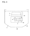
FIG. 3 is a top plan schematic view of the counter weight ofFIG. 2 showing the state in which the cover is removed; -
Fig. 4 is a perspective schematic view of the diesel particulate filter and its peripheral components that are received in the counter weight ofFIG. 2 ; -
Fig. 5 is a front elevational view of the diesel particulate filter and its peripheral components ofFIG. 4 seen from the rear side of the vehicle; -
FIG. 6 is a schematic longitudinal sectional view of the diesel particulate filter and its peripheral components ofFIG. 4 ; -
FIG. 7 is a schematic illustrating operations for attachment and detachment of the diesel particulate filter ofFIG. 4 ; -
FIG. 8 is a perspective schematic view showing a variant of the cover ofFIG. 2 ; -
FIG. 9A is a top plan view of the cover ofFIG. 8 ; and -
FIG. 9B is a front elevational view of the cover ofFIG. 8 . - Embodiments of the present invention will be hereinafter described in accordance with the appended drawings.
-
FIGS. 1 to 7 illustrate a diesel particulate filter mounting structure according to an embodiment of the present invention. Here, a forklift or a forklift truck is taken as an example of an industrial vehicle. - As shown in
FIG. 1 , aforklift 1 includes avehicle body 2, a handling device 3 such as a fork provided in front of thevehicle body 2, and acounter weight 4 provided at the rear of thevehicle body 2. - The
counter weight 4 has, as shown inFIG. 2 , an opening 4a that is formed in and extends through anupper panel 4A of thecounter weight 4 and that is centrally disposed in a lateral direction (i.e. in the left to right direction ofFIG. 2 ) of theupper panel 4A. Theopening 4a has acover 5 detachably fitted thereto via a screw or the like for closing theopening 4a. Thecover 5 has a throughhole 5a formed therein. Amuffler 40 is inserted into the throughhole 5a and extends upwardly. - As shown in
FIG. 3 , there is provided adiesel particulate filter 6 in thecounter weight 4. Thediesel particulate filter 6 is for collecting and removing particulate matter (PM) included in emission of a diesel engine. An exhaust gas intake side of thediesel particulate filter 6 is connected to anexhaust pipe 60 extending from anengine 10 and an exhaust gas outlet side of thediesel particulate filter 6 is connected to an end of themuffler 40. Theopening 4a of thecounter weight 4 is sized so that thediesel particulate filter 6 can pass through theopening 4a vertically. Thediesel particulate filter 6 is laterally biased toward either one (in this case, to the right side) of opposite sides of the vehicle. Thereby, thediesel particulate filter 6 is laterally offset relative to theopening 4a of thecounter weight 4. - In
FIG. 3 , areference numeral 7 depicts a radiator and theradiator 7 holds cooling water for cooling the engine. Areference numeral 8 depicts a fan shroud and thefan shroud 8 is an air introduction device that introduces airflow generated by a fan toward theradiator 7 to cool theradiator 7. - The
diesel particulate filter 6 is, as shown inFIG. 4 , disposed at the rear of theengine 10 and connected with theexhaust pipe 60 extending from theengine 10. In this embodiment, theexhaust pipe 60 of theengine 10 extends from the right side of theengine 10 and thediesel particulate filter 6 is laterally biased to the right side of the vehicle as mentioned above. Therefore, piping between thediesel particulate filter 6 and theengine 10 can be performed by the shortest route. - The
diesel particulate filter 6 is provided onframes frames FIG. 5 , formed of a pair of base plates each extending in a width direction of the vehicle (i.e. in a left to right direction ofFIG. 5 ). Theframes FIG. 5 (seeFIG. 4 ). - The
diesel particulate filter 6 is installed on theframes fittings 63 such as angle plates. An upper portion of the fitting 63 is fixed to a bottom portion of thediesel particulate filter 6 and a lower portion of the fitting 63 is fixedly attached to theframes screw 64. InFIGS. 4 and5 , areference numeral 65 denotes a nut that is screwed into thescrew 64. Thescrew 64 may be fixed to theframes diesel particulate filter 6. The fitting 63 may have an elongated aperture formed therein for insertion of thescrew 64 in order to facilitate positioning of thediesel particulate filter 6 at the time of attachment of thediesel particulate filter 6.FIGS. 4 and5 show an example in which three pieces of angle plates are provided asfittings 63, but number of the angle plates may be two or more than four. - There is provided a
rubber vibration insulator 66 around thescrew 64 between the fitting 63 and theframe diesel particulate filter 6 on therubber vibration insulator 66, vibration during driving of the vehicle is prevented from being directly transmitted to thediesel particulate filter 6. However, such arubber vibration insulator 66 is not an essential member. - The
counter weight 4 has anopening 4b formed in and extending longitudinally through arear panel 4B thereof (seeFIG. 6 ). Thescrews 64 and the nuts 65 face theopening 4b (see a double dotted line ofFIG. 5 ). - Next, maintenance work of the
diesel particulate filter 6 will be explained hereinafter. - At the time of maintenance, a worker opens the
cover 5 that closes theopening 4a of theupper panel 4A of thecounter weight 4, and removes thecover 4 from theopening 4a. Then, thediesel particulate filter 6 is exposed through theopening 4a (seeFIG. 3 ). From this state, the worker removes theexhaust pipe 60 that is connected to thediesel particulate filter 6 and unscrews the nuts 65 to remove them. Some of the nuts 65 can be removed through theopening 4b of therear panel 4B of thecounter weight 4 before opening the cover 5 (seeFIG. 5 ). - Then, the
diesel particulate filter 6 is lifted at a short distance using a crane or the like, and thus thefittings 63 at the bottom portion of thediesel particulate filter 6 are pulled out of the threaded portion of thescrews 64. From this state, thediesel particulate filter 6 is transferred at a short distance toward the left side of the vehicle (seeFIG. 7 ) to be located directly below or right under theopening 4a. Next, thediesel particulate filter 6 is lifted upwardly out of the vehicle through theopening 4a and placed down on the ground. The worker eliminates of ash or the like that has been accumulated in thediesel particulate filter 6 and exchange a filter of thediesel particulate filter 6. - Thereafter, the
diesel particulate filter 6 is lifted again using a crane or the like and introduced into thecounter weight 4 through theopening 4a of theupper panel 4A of thecounter weight 4. Thediesel particulate filter 6 is then transferred at a short distance toward the right side of the vehicle to align the positions of apertures of thefittings 63 with the positions of the thread portions of thescrews 64. Then, thediesel particulate filter 6 is lowered downwardly and thus the thread portions of thescrews 64 are inserted into the apertures of thefittings 63. The nuts 65 are fitted to the thread portions of thescrews 64 to be tightened. Then, theexhaust pipe 60 is fitted to thediesel particulate filter 6 and thecover 5 is returned to theopening 4a. In such a manner, the maintenance work of thediesel particulate filter 6 is completed. - According to such an embodiment of the present invention, when performing maintenance of the
diesel particulate filter 6, a maintenance worker has only to take thediesel particulate filter 6 out of the vehicle utilizing theopening 4a formed vertically through thecounter weight 4. Similarly, when putting thediesel particulate filter 6 back into the vehicle, the worker has only to utilize theopening 4a formed vertically through thecounter weight 4. In this way, during maintenance of thediesel particulate filter 6, attachment and detachment of thediesel particulate filter 6 can be facilitated without detaching or removing thecounter weight 4. As a result of this, maintenance of thediesel particulate filter 6 can be improved. - Moreover, in the mounting structure of the
diesel particulate filter 6 according to an embodiment of the present invention, since themuffler 40 connected to thediesel particulate filter 6 is disposed above thecounter weight 4, maintenance of themuffler 40 and its peripheral components can be also facilitated. - Also, as shown in
FIG. 6 , as themuffler 40 is disposed above thecounter weight 4, there is formed an inner space below thediesel particulate filter 6 in thecounter weight 4. The outside air introduced from the front portion of the vehicle can flow toward the rear portion of the vehicle through such an inner space (see an arrow mark inFIG. 6 ) and the air can flow out of the vehicle through theopening 4b of therear panel 4B of thecounter weight 4. - At this time, it is possible for the outside air to pass through another inner space formed above the
diesel particulate filter 6 in thecounter weight 4, but in order to achieve such an air flow effectively thecover 5 may have a rib formed on an inside surface of thecover 5 to introduce the air. -
FIGS. 8 ,9A, and 9B illustrate a variant of thecover 5 with such a rib. As shown in these drawings, thecover 5 is formed of a pair ofside plates top plate 5C, and aback plate 5D. A front surface and a bottom surface of thecover 5 are openings. Thecover 5 is installed in thecounter weight 4 with theback plate 5D facing toward the engine side (i.e. to the front side of the vehicle) (seeFIG. 6 ). - The
side plates cover 5 are provided with plate-like ribs (or air rectifying plates) 50, 51 respectively that each extend in the longitudinal direction of the vehicle (i.e. the direction perpendicular to the page ofFIG. 9A ). Thetop plate 5C of thecover 5 is provided with three plate-like ribs (or air rectifying plates) 52, 53, 54 that are placed at a predetermined spacing and that extend substantially in the longitudinal direction of the vehicle. The centrally placedrib 52 extends along the longitudinal direction of the vehicle. Theribs rib 52 approach therib 52 gradually or incline inwardly toward the rib 52 (seeFIGS. 8 and9A ) as it go toward the rear side of the vehicle (i.e. the bottom side ofFIG. 9A ). Such an arrangement allows for the outside air introduced from the front part of the vehicle to be rectified and forwarded toward the rear part of the vehicle (see arrow marks ofFIG. 9A ). In this case, thecover 5 functions as a rear shroud that can rectify engine cooling air flow and forward the air flow toward the rear part of the vehicle. - In the above-mentioned embodiment, the diesel particulate filter mounting structure according to an aspect of the present invention was applied to a forklift, but the present invention also has application to other industrial vehicles such as a shovel loader and the like.
- The present invention is suitable to industrial vehicles equipped with counter weights such as forklifts, shovel loaders and the like.
Claims (10)
- A mounting structure for installing a diesel particulate filter to remove particulate matter included in emission of an engine of an industrial vehicle,
the industrial vehicle including a vehicle body, a handling device provided in front of the vehicle body, and a counter weight provided at the rear of the vehicle body and housing the diesel particulate filter,
the particulate filter being detachably fitted to a frame that is provided at the rear of the vehicle body, and the counter weight having an opening formed therein and extending therethrough, which is sized so that the diesel particulate filter can pass through the opening vertically. - The mounting structure according to claim 1, wherein the diesel particulate filter is fastened with a screw at the frame.
- The mounting structure according to claim 1 or 2, wherein the diesel particulate filter is provided at the frame via a rubber vibration insulator.
- The mounting structure according to claim 2, wherein the counter weight has another opening formed in and extending through a rear surface thereof, the screw facing the another opening.
- The mounting structure according to claim 1, wherein the diesel particulate filter is laterally biased toward either one of opposite sides of the vehicle body.
- The mounting structure according to claim 1, wherein the opening is disposed laterally centrally at the counter weight.
- The mounting structure according to claim 1, wherein the opening has a cover detachably fitted thereto for closing the opening, the cover having a muffler fitted therethrough, the muffler being connected to the diesel particulate filter.
- The mounting structure according to claim 7, wherein the cover has a rib formed on an inner surface of the cover for introducing air flow.
- The mounting structure according to claim 8, wherein the cover acts as a rear shroud for introducing engine cooling air flow toward the rear of the vehicle.
- The mounting structure according to claim 1, wherein the industrial vehicle is a forklift or a shovel loader.
Applications Claiming Priority (2)
| Application Number | Priority Date | Filing Date | Title |
|---|---|---|---|
| JP2010256862A JP2012106836A (en) | 2010-11-17 | 2010-11-17 | Diesel particulate filter mounting structure for industrial vehicle |
| PCT/JP2011/076472 WO2012067170A1 (en) | 2010-11-17 | 2011-11-10 | Diesel particulate filter mounting structure for industrial vehicle |
Publications (2)
| Publication Number | Publication Date |
|---|---|
| EP2641769A1 true EP2641769A1 (en) | 2013-09-25 |
| EP2641769A4 EP2641769A4 (en) | 2014-05-07 |
Family
ID=46084091
Family Applications (1)
| Application Number | Title | Priority Date | Filing Date |
|---|---|---|---|
| EP20110842338 Withdrawn EP2641769A4 (en) | 2010-11-17 | 2011-11-10 | Diesel particulate filter mounting structure for industrial vehicle |
Country Status (4)
| Country | Link |
|---|---|
| US (1) | US20130175109A1 (en) |
| EP (1) | EP2641769A4 (en) |
| JP (1) | JP2012106836A (en) |
| WO (1) | WO2012067170A1 (en) |
Families Citing this family (10)
| Publication number | Priority date | Publication date | Assignee | Title |
|---|---|---|---|---|
| JP5842887B2 (en) * | 2013-09-19 | 2016-01-13 | コベルコ建機株式会社 | Work machine |
| WO2016016936A1 (en) * | 2014-07-29 | 2016-02-04 | ニチユ三菱フォークリフト株式会社 | Industrial vehicle |
| JP6009063B2 (en) * | 2014-08-19 | 2016-10-19 | 株式会社小松製作所 | Work vehicle |
| US10377227B2 (en) | 2014-08-21 | 2019-08-13 | Mitsubishi Logisnext Co., LTD. | Industrial vehicle |
| JP5904626B1 (en) * | 2014-08-21 | 2016-04-13 | ニチユ三菱フォークリフト株式会社 | Industrial vehicle |
| JP5904625B1 (en) * | 2014-08-21 | 2016-04-13 | ニチユ三菱フォークリフト株式会社 | Industrial vehicle |
| US9670646B2 (en) * | 2015-03-10 | 2017-06-06 | Komatsu Ltd. | Working vehicle |
| JP6881334B2 (en) * | 2018-01-29 | 2021-06-02 | 株式会社豊田自動織機 | Exhaust gas purification device |
| JP7067326B2 (en) * | 2018-07-12 | 2022-05-16 | 株式会社豊田自動織機 | Installation structure of exhaust gas purification device |
| US11555289B2 (en) | 2020-06-30 | 2023-01-17 | Caterpillar Inc. | Construction vehicle |
Family Cites Families (102)
| Publication number | Priority date | Publication date | Assignee | Title |
|---|---|---|---|---|
| US2264512A (en) * | 1939-04-14 | 1941-12-02 | Clark Equipment Co | Industrial truck |
| US2256314A (en) * | 1939-04-14 | 1941-09-16 | Clark Equipment Co | Industrial truck |
| US2387485A (en) * | 1943-08-28 | 1945-10-23 | Young Radiator Co | Heat exchange unit for radial type engines |
| US2456512A (en) * | 1943-12-31 | 1948-12-14 | Hyster Co | Muffler for internal-combustion engines |
| US2561300A (en) * | 1948-09-24 | 1951-07-17 | Coventry Climax Eng Ltd | Industrial truck |
| US2931452A (en) * | 1956-05-18 | 1960-04-05 | Clark Equipment Co | Hood means for industrial trucks and the like |
| US2924296A (en) * | 1957-07-25 | 1960-02-09 | Clark Equipment Co | Dry muffler and mounting means therefor |
| US3540540A (en) * | 1968-05-08 | 1970-11-17 | Hyster Co | Cooling system for lift trucks |
| US3664129A (en) * | 1968-05-08 | 1972-05-23 | Hyster Co | Hydraulic cooling system |
| US3897847A (en) * | 1972-06-26 | 1975-08-05 | Deere & Co | Tractor front end construction |
| US4011849A (en) * | 1976-02-05 | 1977-03-15 | Deere & Company | Combined engine and muffler compartment |
| DE2655441A1 (en) * | 1976-12-07 | 1978-06-08 | Linde Ag | LIFT LOADER WITH INTERNAL COMBUSTION ENGINE |
| US4117902A (en) * | 1977-02-07 | 1978-10-03 | Clark Equipment Company | Engine cooling system for a skid-steer loader |
| US4133547A (en) * | 1977-07-11 | 1979-01-09 | Massey-Ferguson Inc. | Engine componentry |
| DD140105A1 (en) * | 1978-12-27 | 1980-02-13 | Dieter Berth | AIR GUIDE TO THE COOLING SYSTEM AND DRIVE MOTOR OF A SELF-OPERATING AGRICULTURAL MACHINE |
| US4338890A (en) * | 1979-01-31 | 1982-07-13 | Caterpillar Tractor Co. | Hood, muffler and air cleaner module for an internal combustion engine |
| JPS55148607A (en) * | 1979-05-10 | 1980-11-19 | Nissan Motor Co Ltd | Seat cooling device for industrial vehicle |
| JPS6132098Y2 (en) * | 1981-03-26 | 1986-09-18 | ||
| US4471853A (en) * | 1983-06-20 | 1984-09-18 | Towmotor Corporation | Mounting arrangement for an exhaust system |
| US4696361A (en) * | 1984-03-23 | 1987-09-29 | Owatonna Manufacturing Company | Swing-up radiator and oil cooler assembly |
| US4862981A (en) * | 1984-12-24 | 1989-09-05 | Kawasaki Jukogyo Kabushiki Kaisha | Internal combustion engine and devices employing same |
| US4776417A (en) * | 1985-10-30 | 1988-10-11 | Honda Giken Kogyo Kabushiki Kaisha | Vehicle with radiator |
| GB2203107B (en) * | 1987-04-09 | 1991-05-29 | Linde Ag | Vehicle having a soundproofed drive unit |
| US4815550A (en) * | 1987-08-21 | 1989-03-28 | Clark Equipment Company | Engine cooling system for skid steer loaders |
| JP2737159B2 (en) | 1988-06-20 | 1998-04-08 | 株式会社豊田自動織機製作所 | Balance weight of cargo handling vehicle |
| JPH0233727U (en) * | 1988-08-30 | 1990-03-02 | ||
| US5042602A (en) * | 1989-08-18 | 1991-08-27 | Toyo Umpanki Co., Ltd. | Loader |
| JP2913751B2 (en) * | 1990-04-23 | 1999-06-28 | 株式会社豊田自動織機製作所 | Cooling system for engine type forklift |
| JP2682223B2 (en) | 1990-10-09 | 1997-11-26 | 日産自動車株式会社 | Balance weight support structure for industrial vehicles |
| JP2664102B2 (en) * | 1991-07-11 | 1997-10-15 | 株式会社クボタ | Power structure of lawn mower |
| US5692467A (en) * | 1991-08-23 | 1997-12-02 | Caterpillar Inc. | Ventilation apparatus for an enclosure |
| JP2591095Y2 (en) | 1992-05-14 | 1999-02-24 | 日産ディーゼル工業株式会社 | Mounting structure of particulate trap filter |
| JPH0688524A (en) * | 1992-09-08 | 1994-03-29 | Kubota Corp | Engine part structure of farm working vehicle |
| US5626185A (en) * | 1994-07-05 | 1997-05-06 | Ford Motor Company | Airflow ejector system for an automotive vehicle with wheel-well ejectors |
| US5645134A (en) * | 1995-11-14 | 1997-07-08 | Caterpillar Inc. | Engine enclosure assembly |
| US6296436B1 (en) * | 1997-04-08 | 2001-10-02 | Allied Gator, Inc. | Multipurpose counterweight housing and counterweight |
| US6688424B1 (en) * | 1997-10-24 | 2004-02-10 | Komatsu Ltd. | Noise absorbing device and device for taking air into engine room of a construction machine |
| GB2336662B (en) * | 1998-04-21 | 2002-04-10 | Agco Gmbh & Co | Vehicle cooling radiator arrangement |
| JP2000062474A (en) * | 1998-08-21 | 2000-02-29 | Komatsu Ltd | Work vehicle cooling system |
| JP3659391B2 (en) * | 1998-09-28 | 2005-06-15 | コベルコ建機株式会社 | Construction machinery |
| US6216778B1 (en) * | 1998-12-30 | 2001-04-17 | Case Corporation | Cooling system for an off-highway vehicle |
| US6257359B1 (en) * | 1999-06-28 | 2001-07-10 | Clark Equipment Company | Air handling system for engines |
| US6481748B1 (en) * | 1999-07-30 | 2002-11-19 | Komatsu Ltd. | Counterweight for construction vehicle |
| US6321830B1 (en) * | 1999-12-15 | 2001-11-27 | Caterpillar Inc. | Cooling system for a work machine |
| JP4450298B2 (en) * | 2000-01-12 | 2010-04-14 | 株式会社小松製作所 | Engine cooling air passage for construction machinery |
| JP2002146843A (en) * | 2000-11-14 | 2002-05-22 | Shin Caterpillar Mitsubishi Ltd | Construction equipment |
| CN1201055C (en) * | 2000-12-01 | 2005-05-11 | 日立建机株式会社 | Construction machinery |
| JP3885495B2 (en) * | 2000-12-27 | 2007-02-21 | 日産自動車株式会社 | Electrical unit mounting structure |
| JP3578336B2 (en) * | 2001-01-11 | 2004-10-20 | 日本輸送機株式会社 | Counterbalance type forklift |
| JP4753496B2 (en) * | 2001-07-06 | 2011-08-24 | 株式会社小松製作所 | Work vehicle with upper turning function |
| JP3978320B2 (en) * | 2001-07-31 | 2007-09-19 | 新キャタピラー三菱株式会社 | Construction machinery with built-in exhaust gas reduction device |
| US20050160724A1 (en) * | 2002-02-04 | 2005-07-28 | Valentine James M. | Reduced-emissions combustion utilizing multiple-component metallic combustion catalyst and lightly catalyzed diesel oxidation catalyst |
| DE10232427A1 (en) * | 2002-07-17 | 2004-01-29 | Still Gmbh | Counter weight for mobile work machine e.g. fork lift truck has recess with demountable cover for protection but allowing easy access to fittings for maintenance |
| JP2004218570A (en) | 2003-01-16 | 2004-08-05 | Hino Motors Ltd | Particulate filter mounting structure |
| JP3952972B2 (en) * | 2003-03-07 | 2007-08-01 | コベルコ建機株式会社 | Construction machine cooling system |
| JP4196701B2 (en) * | 2003-03-11 | 2008-12-17 | 株式会社豊田自動織機 | Industrial vehicle body structure and industrial vehicle having the body structure |
| JP4211919B2 (en) * | 2003-03-24 | 2009-01-21 | 株式会社小松製作所 | Hydraulic excavator counterweight |
| JP4019992B2 (en) * | 2003-03-27 | 2007-12-12 | コベルコ建機株式会社 | Counterweight mounting structure |
| JP4075661B2 (en) * | 2003-03-28 | 2008-04-16 | コベルコ建機株式会社 | Work machine |
| US7255189B2 (en) * | 2004-06-18 | 2007-08-14 | Cnh America Llc | Radiator mounting system |
| US7014007B2 (en) * | 2004-06-30 | 2006-03-21 | Mitsubishi Heavy Industries, Ltd. | Body structure of forklift truck |
| US7028646B1 (en) * | 2004-12-21 | 2006-04-18 | Cnh America Llp | Cooling system for skid steer loader including fan assembly mounted to engine |
| EP1832731B1 (en) * | 2004-12-27 | 2018-08-15 | Kobelco Construction Machinery Co., Ltd. | Cooling structure of construction machine |
| WO2006080495A1 (en) * | 2005-01-31 | 2006-08-03 | Komatsu Ltd. | Working vehicle |
| US20070007061A1 (en) * | 2005-07-06 | 2007-01-11 | Deere & Company | Plenum cooling system |
| JP4544121B2 (en) * | 2005-09-29 | 2010-09-15 | コベルコ建機株式会社 | Construction machinery |
| JP5122786B2 (en) * | 2005-11-18 | 2013-01-16 | 株式会社小松製作所 | Counterweight attachment / detachment device |
| JP2007205097A (en) * | 2006-02-03 | 2007-08-16 | Shin Caterpillar Mitsubishi Ltd | Counterweight for working machine |
| JP4270239B2 (en) * | 2006-08-11 | 2009-05-27 | コベルコ建機株式会社 | Construction machinery |
| US7467722B2 (en) * | 2006-08-31 | 2008-12-23 | Ramun John R | Counterweight for heavy equipment |
| US8212563B2 (en) * | 2006-10-31 | 2012-07-03 | Active Spectrum, Inc. | Method and apparatus for in-situ measurement of soot by electron spin resonance (ESR) spectrometry |
| JP2008156835A (en) * | 2006-12-21 | 2008-07-10 | Shin Caterpillar Mitsubishi Ltd | Construction machinery provided with exhaust gas posttreatment system |
| JP4594942B2 (en) * | 2007-01-16 | 2010-12-08 | コベルコ建機株式会社 | Construction machine cooling structure |
| EP2163693B1 (en) * | 2007-06-26 | 2013-11-06 | Hitachi Construction Machinery Co., Ltd | Construction machine |
| JP4900163B2 (en) * | 2007-09-26 | 2012-03-21 | コベルコ建機株式会社 | Construction machinery |
| JP5278650B2 (en) * | 2007-12-26 | 2013-09-04 | ニチユ三菱フォークリフト株式会社 | Fuel tank mounting mechanism and industrial vehicle equipped with the mechanism |
| JP4928474B2 (en) * | 2008-01-08 | 2012-05-09 | 日立建機株式会社 | Arrangement structure of NOx reduction device for construction machinery |
| JP5101324B2 (en) * | 2008-02-07 | 2012-12-19 | 日立建機株式会社 | Arrangement structure of NOx reduction device for construction machinery |
| JP5172381B2 (en) * | 2008-02-22 | 2013-03-27 | 日立建機株式会社 | Construction machinery |
| JP2009209647A (en) * | 2008-03-06 | 2009-09-17 | Hitachi Constr Mach Co Ltd | Heat exchanger of construction machine |
| JP2009274651A (en) * | 2008-05-16 | 2009-11-26 | Toyota Industries Corp | Hybrid industrial vehicle |
| CN102036846B (en) * | 2008-05-22 | 2013-11-06 | 日立建机株式会社 | Construction machine |
| JP4705130B2 (en) * | 2008-06-25 | 2011-06-22 | 日立建機株式会社 | Construction machinery |
| JP4880779B2 (en) * | 2008-07-31 | 2012-02-22 | 日立建機株式会社 | Construction machinery |
| JP4831845B2 (en) * | 2008-08-19 | 2011-12-07 | 三菱重工業株式会社 | Battery cooling structure for hybrid industrial vehicles |
| US8104559B2 (en) * | 2008-09-22 | 2012-01-31 | Clark Equipment Company | Multiple air flow paths using single axial fan |
| EP2341227B1 (en) * | 2008-10-28 | 2018-08-29 | Yanmar Co., Ltd. | Engine device for mounting on working vehicle |
| JP5169766B2 (en) * | 2008-11-20 | 2013-03-27 | コベルコ建機株式会社 | Muffler mounting device for construction machinery |
| JP5401944B2 (en) * | 2008-11-25 | 2014-01-29 | コベルコ建機株式会社 | Muffler mounting device for construction machinery |
| JP4905446B2 (en) * | 2008-12-24 | 2012-03-28 | 株式会社豊田自動織機 | Industrial vehicle |
| JP4801754B2 (en) * | 2009-03-25 | 2011-10-26 | 三菱重工業株式会社 | forklift |
| JP5178923B2 (en) * | 2010-01-26 | 2013-04-10 | 株式会社小松製作所 | Engine hood for construction machinery |
| EP2423149B1 (en) * | 2010-08-24 | 2016-11-23 | Manitowoc Crane Group France SAS | Mounting for an auxiliary lifting device on a mobile crane |
| JP5368398B2 (en) * | 2010-09-10 | 2013-12-18 | 日立建機株式会社 | Work machine |
| JP5630216B2 (en) * | 2010-10-29 | 2014-11-26 | コベルコ建機株式会社 | Construction machinery |
| US20120103712A1 (en) * | 2010-11-03 | 2012-05-03 | Caterpillar Inc. | Skid steer machine having pivotably mounted cooling system and non-metallic vibration isolator |
| PL2479398T3 (en) * | 2011-01-25 | 2017-10-31 | Joseph Voegele Ag | Road paver or feeder |
| JP5594197B2 (en) * | 2011-03-16 | 2014-09-24 | コベルコ建機株式会社 | Construction machine cooling structure |
| JP5274610B2 (en) * | 2011-03-31 | 2013-08-28 | 株式会社小松製作所 | Construction machinery |
| USD678358S1 (en) * | 2012-02-29 | 2013-03-19 | Hitachi Construction Machinery Co., Ltd. | Counterweight for construction machine |
| JP5261589B1 (en) * | 2012-04-24 | 2013-08-14 | 株式会社小松製作所 | Bulldozer |
| USD684603S1 (en) * | 2012-05-10 | 2013-06-18 | Hitachi Construction Machinery Co., Ltd. | Weight for a construction machine |
-
2010
- 2010-11-17 JP JP2010256862A patent/JP2012106836A/en active Pending
-
2011
- 2011-11-10 EP EP20110842338 patent/EP2641769A4/en not_active Withdrawn
- 2011-11-10 WO PCT/JP2011/076472 patent/WO2012067170A1/en not_active Ceased
- 2011-11-10 US US13/823,874 patent/US20130175109A1/en not_active Abandoned
Also Published As
| Publication number | Publication date |
|---|---|
| WO2012067170A1 (en) | 2012-05-24 |
| EP2641769A4 (en) | 2014-05-07 |
| JP2012106836A (en) | 2012-06-07 |
| US20130175109A1 (en) | 2013-07-11 |
Similar Documents
| Publication | Publication Date | Title |
|---|---|---|
| EP2641769A1 (en) | Diesel particulate filter mounting structure for industrial vehicle | |
| US9434245B2 (en) | Industrial vehicle | |
| US8833500B2 (en) | Work vehicle | |
| JP5983054B2 (en) | Hybrid vehicle battery pack cooling structure | |
| US9388730B2 (en) | Ventilation structure for engine compartment | |
| CN104114775B (en) | Hydraulic crawler excavator | |
| US10106954B2 (en) | Construction machine | |
| US20140056675A1 (en) | Wheel loader | |
| CN104039576B (en) | Working truck | |
| KR20160133408A (en) | Engine device and stationary work machine having same mounted | |
| US9290907B2 (en) | Work vehicle | |
| TWI499531B (en) | Two-wheeled vehicle | |
| JP2006342704A (en) | Work vehicle | |
| JP2014193664A (en) | Construction machine | |
| KR100656040B1 (en) | Radiator Guard of Wheel Loader | |
| US10144379B1 (en) | Radiator guard assembly | |
| JP2009292611A (en) | Work vehicle | |
| US8919817B2 (en) | Bulldozer | |
| JP3655828B2 (en) | Engine auxiliary equipment support device for traveling vehicle | |
| JP5091772B2 (en) | Work vehicle | |
| CN105189244A (en) | Radiator fan assembly | |
| EP4249688A1 (en) | Construction machine | |
| CN217069190U (en) | Resonance crusher power assembly and resonance crusher | |
| US20140261286A1 (en) | Modular structure supporting engine enclosure | |
| JP2009292610A (en) | Work vehicle |
Legal Events
| Date | Code | Title | Description |
|---|---|---|---|
| PUAI | Public reference made under article 153(3) epc to a published international application that has entered the european phase |
Free format text: ORIGINAL CODE: 0009012 |
|
| 17P | Request for examination filed |
Effective date: 20130322 |
|
| AK | Designated contracting states |
Kind code of ref document: A1 Designated state(s): AL AT BE BG CH CY CZ DE DK EE ES FI FR GB GR HR HU IE IS IT LI LT LU LV MC MK MT NL NO PL PT RO RS SE SI SK SM TR |
|
| DAX | Request for extension of the european patent (deleted) | ||
| A4 | Supplementary search report drawn up and despatched |
Effective date: 20140409 |
|
| RIC1 | Information provided on ipc code assigned before grant |
Ipc: B60K 13/04 20060101AFI20140403BHEP Ipc: F01N 13/18 20100101ALI20140403BHEP Ipc: B60K 11/04 20060101ALI20140403BHEP Ipc: F01N 3/02 20060101ALI20140403BHEP Ipc: E02F 9/08 20060101ALI20140403BHEP Ipc: E02F 9/18 20060101ALI20140403BHEP Ipc: B66F 9/075 20060101ALI20140403BHEP |
|
| GRAP | Despatch of communication of intention to grant a patent |
Free format text: ORIGINAL CODE: EPIDOSNIGR1 |
|
| RIC1 | Information provided on ipc code assigned before grant |
Ipc: B60K 13/04 20060101AFI20150430BHEP Ipc: B60K 11/04 20060101ALI20150430BHEP Ipc: E02F 9/18 20060101ALI20150430BHEP Ipc: B66F 9/075 20060101ALI20150430BHEP Ipc: E02F 9/08 20060101ALI20150430BHEP Ipc: F01N 3/02 20060101ALI20150430BHEP Ipc: F01N 13/18 20100101ALI20150430BHEP |
|
| INTG | Intention to grant announced |
Effective date: 20150527 |
|
| STAA | Information on the status of an ep patent application or granted ep patent |
Free format text: STATUS: THE APPLICATION IS DEEMED TO BE WITHDRAWN |
|
| 18D | Application deemed to be withdrawn |
Effective date: 20151007 |