JP4019992B2 - Counterweight mounting structure - Google Patents
Counterweight mounting structure Download PDFInfo
- Publication number
- JP4019992B2 JP4019992B2 JP2003087817A JP2003087817A JP4019992B2 JP 4019992 B2 JP4019992 B2 JP 4019992B2 JP 2003087817 A JP2003087817 A JP 2003087817A JP 2003087817 A JP2003087817 A JP 2003087817A JP 4019992 B2 JP4019992 B2 JP 4019992B2
- Authority
- JP
- Japan
- Prior art keywords
- counterweight
- sound insulating
- insulating material
- mounting structure
- concave groove
- Prior art date
- Legal status (The legal status is an assumption and is not a legal conclusion. Google has not performed a legal analysis and makes no representation as to the accuracy of the status listed.)
- Expired - Fee Related
Links
Images


Classifications
-
- E—FIXED CONSTRUCTIONS
- E02—HYDRAULIC ENGINEERING; FOUNDATIONS; SOIL SHIFTING
- E02F—DREDGING; SOIL-SHIFTING
- E02F9/00—Component parts of dredgers or soil-shifting machines, not restricted to one of the kinds covered by groups E02F3/00 - E02F7/00
- E02F9/18—Counterweights
Landscapes
- Engineering & Computer Science (AREA)
- Mining & Mineral Resources (AREA)
- Civil Engineering (AREA)
- General Engineering & Computer Science (AREA)
- Structural Engineering (AREA)
- Component Parts Of Construction Machinery (AREA)
- Jib Cranes (AREA)
Abstract
Description
【0001】
【発明の属する技術分野】
本発明は、油圧ショベルやクレーン等の建設機械に搭載されるカウンタウエイトの取付構造に関するものである。
【0002】
【従来の技術】
上部旋回体の後部にカウンタウエイトを搭載する油圧ショベルでは、図9の側面断面図に示すように、カウンタウエイト50の内面側複数箇所にウエイト取付用ボルト51を螺合するための固定部52が設けられている。
【0003】
この固定部52と対応して旋回フレーム53の後端部53aには、貫通孔を有するカウンタウエイト支持台座54が設けられており、その支持台座54を軸通させたウエイト取付用ボルト51を上記固定部に設けられた雌ねじ部52aに螺合することにより、旋回フレーム53とカウンタウエイト50とを接続するようになっている。
【0004】
上記旋回フレームの後端部53aと接続されたカウンタウエイト50との間には隙間Sがあるため、この隙間Sを通してエンジンルームから発生する騒音が外部に漏れる。そこで、上記隙間Sを遮断するため、カウンタウエイト50と旋回フレームの後端部53aとの間に、例えば発泡ウレタン樹脂等によってテープ状に成形された弾性を有する遮音材55が圧縮した状態で配置されている。この遮音材55は、通常、後端部53aの上面に両面テープを用いて貼着されている。
【0005】
なお、建設機械において遮音を目的とするものではないが、外装カバーの取付構造において、外装カバーと支持部材との間に隙間を設定し、弾性体からなるシール材でその隙間をシールするようにしたものが知られている(例えば、特許文献1参照)。
【0006】
【特許文献1】
特開平9−189050号公報(第(3)頁、図1)
【0007】
【発明が解決しようとする課題】
図9に示したカウンタウエイト50は、通常、エンジン並びにエンジン周りに配置される部品のメンテナンスを行う際に取り外されるため、カウンタウエイトの脱着作業は頻繁に発生する。
【0008】
脱着作業の際、カウンタウエイト50はクレーン等を用いて吊り上げられ、またこの逆に降ろされるが、このとき、遮音材55をひきはがしたり損傷することがあり、遮音性が次第に低下するという問題があった。
【0009】
本発明は以上のような従来のカウンタウエイト取付構造における課題を考慮してなされたものであり、カウンタウエイトを脱着しても遮音性が低下しないカウンタウエイト取付構造を提供するものである。
【0010】
【課題を解決するための手段】
本発明は、建設機械の上部旋回体におけるカウンタウエイト取付部材に対し、隙間を介してカウンタウエイトが接続されるカウンタウエイト取付構造において、カウンタウエイトの取付面に凹溝を有し、この凹溝に、弾性を有する遮音材を取り付け、カウンタウエイト装着状態で凹溝の開口から突出させた遮音材がカウンタウエイト取付部材の垂直面に対して外側から当接し圧縮されるように構成したカウンタウエイト取付構造である。
【0011】
本発明に従えば、カウンタウエイト取付部材とカウンタウエイトとの隙間を遮断する遮音材をカウンタウエイトの凹溝に取り付け、カウンタウエイト取付部材の垂直面に対して圧縮させて騒音の伝播経路を遮断するようにしたため、カウンタウエイト脱着時にカウンタウエイトに引きずられて遮音材がはがれたり損傷することが防止され、また、遮音材にこじる力が作用しても凹溝内に装着されているため脱落を防止することができる。
【0012】
本発明において、上記カウンタウエイト取付部材としての旋回フレームの後端部に対し、隙間を介してカウンタウエイトが接続される場合、旋回フレームの後端部と略水平方向に対向するカウンタウエイト内面に凹溝を形成することができる。それにより、旋回フレームとカウンタウエイトとの間の比較的大きな隙間についても遮音性を維持することができる。
【0013】
本発明において、上記凹溝に仕切部を有し、この仕切部を境として遮音材を複数に分割して配置し、その仕切部の内側に水抜き通路を形成したため、水抜き機能を確保しつつ遮音性を維持することができる。
【0014】
本発明において、上記カウンタウエイト取付部材には、上記仕切部及び上記遮音材に対向するようにこれら仕切部及び遮音材に対して略水平方向に近接して配置されるとともに、上記水抜き通路の幅よりも大きい幅を有し、上記カウンタウエイトが取り付けられるウエイト支持台座が設けられ、そのウエイト支持台座と上記遮音材との間に上記水抜き通路を通して外部に漏れる騒音を減衰させるためのラビリンス構造が設けられるように構成すれば、水抜き通路を設けた場合の遮音性をより高めることができる。
【0015】
【発明の実施の形態】
以下、図面に示した実施の形態に基づいて本発明を詳細に説明する。
【0016】
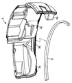
図1は、本発明に係るカウンタウエイトと上部旋回体の旋回フレームの配置を平面で示したものである。
【0017】
同図において、旋回フレーム1は後方小旋回型のものであり、前側中央には接続用ブラケット2が突出して設けられ、この接続用ブラケット2には、垂直軸まわりに回転できるスイングブラケット(図示しない)が連結され、そのスイングブラケットに作業アタッチメント(図示しない)が備えられる。
【0018】
また、上部旋回体後部の旋回半径が車幅内に収まるように、旋回フレーム1の後端部1aは円弧状に形成されており、この円弧状の後端部1aに沿って円弧状に形成されたカウンタウエイト3が配置されている。
【0019】
このカウンタウエイト3は鋳造によって成形されたものであり、その左右両側および略中央にはカウンタウエイト3を旋回フレーム1の各ウエイト支持台座4(後述する)に固定するための固定部3a,3bおよび3cが設けられている。
【0020】
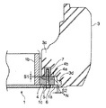
図2は、図1のA−A矢視断面を示したものである。同図において、旋回フレーム1の下側から挿入され、各ウエイト支持台座4を貫通した3本のウエイト取付用ボルト5は上記固定部3a,3bおよび3c(図2では固定部3cのみ現れている)にそれぞれ螺合するようになっている。
【0021】
詳しくは、旋回フレーム1の後端部1aにはウエイト支持台座4が固定されており、このウエイト支持台座4にはウエイト取付用ボルト5の首部を貫通させる貫通孔4aが形成され、この貫通孔4aと連通して後端部1aには開口1cが形成されている。上記開口1cはワッシャ6を遊嵌できる程度の大きさに形成されている。
【0022】
上記ウエイト取付用ボルト5に対応してカウンタウエイト3の固定部3cには雌ねじ部7が固定されている。
【0023】
なお、固定部3c底面とウエイト支持台座4上面との間S1には高さ調整のためのシム4bが挿入されている。
【0024】
また、図中、1bは旋回フレーム1から立設されたガードプレートであり、矢印Nはエンジンルーム等から発生した騒音が外部に漏れる経路を示している。
【0025】
この騒音の漏れを防止するため、本実施形態では図3に示すように、カウンタウエイト3の前側(取付面)下部に、凹溝3dを全幅にわたって円弧状に形成し、この凹溝3dに、例えば発泡ウレタン樹脂、グラスウール等の弾性を有する遮音材8を帯状に成形したものを嵌め入れている。
【0026】
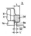
図4は、その遮音材8の取付状態を拡大して示したものである。
【0027】
同図において、遮音材8は矩形断面を有し、凹溝3dに圧縮した状態で押し込むことにより、断面における上面の一部、後面および下面の一部が凹溝3dに保持されるようになっている。
【0028】
遮音材8において凹溝3dの下縁3eから突出する長さをL′、カウンタウエイト3が装着された場合の、旋回フレームの後端部1aと下縁3eとの隙間S2とするとき、L′>S2となるように遮音材8の前後方向の長さLが設定されている。すなわち、遮音材8の前側面の一部8aが、旋回フレーム1の後端部(カウンタウエイト取付部材)1aと当接して圧縮変形できる長さに設定されている。それにより、騒音伝播経路N(図2参照)を遮断するようになっている。
【0029】
なお、後端部1aとの接触面積を多くしたい場合は、後端部1aの縁部上面に円弧状の補助板を立設すればよい。
【0030】
このように遮音材8をカウンタウエイト3側に取り付けるとともに凹溝3dに嵌合したため、カウンタウエイト3の脱着を繰り返しても遮音材8はその凹溝3dによって保護されるため、遮音性を長期にわたって維持することができるようになる。
【0031】
図5は本発明に係るカウンタウエイト取付構造の第二実施形態を示したものである。
【0032】
なお、図5において、図1およびその部分拡大図である図2と同じ構成要素については同一符号を付してその説明を省略する。
【0033】
図5に示す構成が図1のそれと異なる点は、排水用の水抜き通路9が設けられていることである。
【0034】
このように水抜き通路9が設ける必要がある場合は、その水抜き通路9を境として遮音材8aおよび8bを左右に分かれて配置する。この構成では水抜き通路9に遮音材8a,8bが存在しないため、その水抜き通と9を通して騒音が外部に漏れることになる。
【0035】
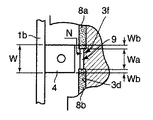
図6は図5のB部を拡大したものである。
【0036】
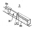
同図に示すように、ウエイト支持台座4の幅Wと水抜き通路9の幅Waは、W>Waの関係に構成されており、従って対向する各遮音材8a,8bの先端は、凹溝3dからわずかに前側に突出して形成されている凸部(仕切部)3fを挟んでWb分だけ水抜き通路9の中心側に入り込んでいる。また、上記凸部3fは図7に示すように角度θを有する騒音反射面に構成されている。
【0037】
また、上記凸部3fは、遮音材8aおよび8bを凹溝3dに取り付ける際に、遮音材8a,8bの先端位置を示す位置決め手段として機能するようにもなっている。
【0038】
上記水抜き通路9の構成により、図8の矢印Cに示されるように、水は容易にその水抜き通路9から排出されるが、矢印N′で示されるように騒音は凸部3fの騒音反射面に反射されて直接、水抜き通過9を通過することができないようになっている。
【0039】
また、図6の矢印Nに示すように、水抜き通路9に至る経路はラビリンス構造に形成されているため、騒音は直接、水抜き通路9を通過することができず、遮音材8a,8b等に衝突して迂回することによって減衰される。
【0040】
このように、第二の実施形態では水抜き通路9を設けているが、凸部3fの騒音反射面およびラビリンス構造からなる減衰手段を設けているため、遮音効果を得ることができる。
【0041】
なお、上記実施形態ではカウンタウエイト取付部材が旋回フレーム1である場合にその後端部1aとカウンタウエイト3との隙間を遮音する構成を例に取り説明したが、本発明のカウンタウエイト取付構造は、これに限らず、例えば、カウンタウエイト取付部材が機体カバーである場合に、その機体カバーとカウンタウエイト3の隙間を遮音する場合にも適用することができる。
【0042】
【発明の効果】
以上説明したことから明らかなように、請求項1の本発明によれば、カウンタウエイト取付部材とカウンタウエイトとの隙間を遮断する遮音材をカウンタウエイトの凹溝に取り付け、カウンタウエイト取付部材の垂直面に対して圧縮させて騒音の伝播経路を遮断するようにしたため、カウンタウエイト脱着時にカウンタウエイトに引きずられて遮音材がはがれたり損傷することが防止され、遮音材にこじる力が作用しても脱落を防止することができる。
【0043】
請求項2の本発明によれば、カウンタウエイト取付部材としての旋回フレームの後端部と略水平方向に対向するカウンタウエイト内面に凹溝を形成したため、旋回フレームとカウンタウエイトとの間の比較的大きな隙間についても遮音性を維持することができる。
【0044】
請求項3の本発明によれば、上記凹溝に仕切部を有し、この仕切部を境として遮音材を複数に分割して配置し、その仕切部の内側に水抜き通路を形成したため、水抜き機能を確保しつつ遮音性を維持することができる。
【0045】
請求項4の本発明によれば、上記仕切部及び上記遮音材に対向するようにこれら仕切部及び遮音材に対して略水平方向に近接して配置されるとともに上記水抜き通路の幅よりも大きい幅を有するウエイト支持台座と、上記遮音材との間に上記水抜き通路を通して外部に漏れる騒音を減衰させるためのラビリンス構造を設けたため、水抜き通路を設けた場合の遮音性をより高めることができる。
【図面の簡単な説明】
【図1】本発明に係るカウンタウエイトと旋回フレームとの配置を示す平面図である。
【図2】図1のA−A矢視断面図である。
【図3】図1のカウンタウエイトに設けられた凹溝を示す斜視図である。
【図4】凹溝に取り付られた遮音材を示す断面図である。
【図5】本発明のカウンタウエイトの第二実施形態を示す平面図である。
【図6】図5のB部拡大図である。
【図7】凸部の形状を示す斜視図である。
【図8】水抜き通路の機能を説明する断面図である。
【図9】従来のカウンタウエイト取付構造を示す図2相当図である。
【符号の説明】
1 旋回フレーム
1c 開口
2 接続用ブラケット
3 カウンタウエイト
3a,3b,3c 固定部
3d 凹溝
3f 凸部
4 ウエイト支持台座
4a 貫通孔
5 ウエイト取付用ボルト
6 ワッシャ
7 雌ねじ部
8 遮音材
8a,8b 遮音材
9 水抜き通路
N 騒音伝播経路[0001]
BACKGROUND OF THE INVENTION
The present invention relates to a structure for mounting a counterweight mounted on a construction machine such as a hydraulic excavator or a crane.
[0002]
[Prior art]
In the hydraulic excavator in which the counterweight is mounted on the rear part of the upper swing body, as shown in the side sectional view of FIG. 9, there are fixing
[0003]
A
[0004]
Since there is a gap S between the
[0005]
Although not intended for sound insulation in construction machines, in the exterior cover mounting structure, a clearance is set between the exterior cover and the support member, and the clearance is sealed with a sealing material made of an elastic body. Is known (for example, see Patent Document 1).
[0006]
[Patent Document 1]
JP-A-9-189050 (page (3), FIG. 1)
[0007]
[Problems to be solved by the invention]
Since the
[0008]
At the time of detachment work, the
[0009]
The present invention has been made in consideration of the above-described problems in the conventional counterweight mounting structure, and provides a counterweight mounting structure in which sound insulation is not lowered even when the counterweight is detached.
[0010]
[Means for Solving the Problems]
The present invention provides a counterweight mounting structure in which a counterweight is connected via a gap to a counterweight mounting member in an upper swing body of a construction machine. The counterweight has a concave groove on the mounting surface of the counterweight. A counterweight mounting structure in which an elastic sound insulating material is attached, and the sound insulating material protruded from the opening of the concave groove in a state where the counterweight is mounted contacts and compresses the vertical surface of the counterweight mounting member from the outside. It is.
[0011]
According to the present invention, a sound insulating material that blocks the gap between the counterweight mounting member and the counterweight is mounted in the concave groove of the counterweight, and is compressed against the vertical surface of the counterweight mounting member to block the noise propagation path. As a result, the sound insulation is prevented from being peeled off or damaged by being dragged to the counter weight when the counter weight is attached or removed, and it is prevented from falling off because it is mounted in the concave groove even if a force is applied to the sound insulation. can do.
[0012]
In the present invention, when the counterweight is connected via a gap to the rear end of the swivel frame as the counterweight mounting member, the inner surface of the counterweight facing the rear end of the swivel frame in a substantially horizontal direction is recessed. Grooves can be formed. Thereby, the sound insulation can be maintained even for a relatively large gap between the turning frame and the counterweight.
[0013]
In the present invention, the concave groove has a partitioning portion, and the sound insulating material is divided into a plurality of portions with the partitioning portion as a boundary, and a water drainage passage is formed inside the partitioning portion, thus ensuring a water draining function. Sound insulation can be maintained.
[0014]
In the present invention, the counterweight mounting member is disposed in a substantially horizontal direction with respect to the partition portion and the sound insulating material so as to face the partition portion and the sound insulating material, A labyrinth structure for attenuating noise leaking to the outside through the water drainage passage between the weight support base and the sound insulating material, having a weight support base to which the counter weight is attached and having a width larger than the width If the water drainage passage is provided, the sound insulation can be further improved.
[0015]
DETAILED DESCRIPTION OF THE INVENTION
Hereinafter, the present invention will be described in detail based on the embodiments shown in the drawings.
[0016]
FIG. 1 is a plan view showing the arrangement of a counterweight and a swing frame of an upper swing body according to the present invention.
[0017]
In the figure, the revolving
[0018]
Further, the
[0019]
The
[0020]
FIG. 2 shows a cross section taken along the line AA in FIG. In the figure, the three
[0021]
Specifically, a
[0022]
A female screw portion 7 is fixed to the fixing portion 3 c of the
[0023]
A
[0024]
Further, in the figure, 1b is a guard plate erected from the revolving
[0025]
In order to prevent leakage of this noise, in this embodiment, as shown in FIG. 3, a
[0026]
FIG. 4 is an enlarged view of the mounting state of the
[0027]
In the same figure, the
[0028]
When the length of the
[0029]
If it is desired to increase the contact area with the
[0030]
Since the
[0031]
FIG. 5 shows a second embodiment of the counterweight mounting structure according to the present invention.
[0032]
In FIG. 5, the same components as those in FIG. 1 and FIG.
[0033]
The configuration shown in FIG. 5 is different from that shown in FIG. 1 in that a
[0034]
When it is necessary to provide the
[0035]
FIG. 6 is an enlarged view of portion B in FIG.
[0036]
As shown in the figure, the width W of the
[0037]
Further, the
[0038]
With the configuration of the
[0039]
Further, as shown by an arrow N in FIG. 6, since the route to the
[0040]
As described above, the
[0041]
In the above embodiment, when the counterweight mounting member is the
[0042]
【The invention's effect】
As is apparent from the above description, according to the present invention of
[0043]
According to the second aspect of the present invention, since the concave groove is formed in the inner surface of the counterweight that faces the rear end portion of the swing frame as the counterweight mounting member in the substantially horizontal direction, the relative distance between the swing frame and the counterweight is relatively small. Sound insulation can be maintained even for large gaps.
[0044]
According to the third aspect of the present invention, the concave groove has a partitioning portion, and the sound insulating material is divided into a plurality of portions with the partitioning portion as a boundary, and the water drainage passage is formed inside the partitioning portion. Sound insulation can be maintained while ensuring the water draining function.
[0045]
According to this invention of
[Brief description of the drawings]
FIG. 1 is a plan view showing an arrangement of a counterweight and a swing frame according to the present invention.
FIG. 2 is a cross-sectional view taken along the line AA in FIG.
FIG. 3 is a perspective view showing a recessed groove provided in the counterweight of FIG. 1;
FIG. 4 is a cross-sectional view showing a sound insulating material attached to a concave groove.
FIG. 5 is a plan view showing a second embodiment of the counterweight of the present invention.
6 is an enlarged view of a portion B in FIG.
FIG. 7 is a perspective view showing a shape of a convex portion.
FIG. 8 is a cross-sectional view illustrating the function of a water drain passage.
FIG. 9 is a view corresponding to FIG. 2 showing a conventional counterweight mounting structure.
[Explanation of symbols]
DESCRIPTION OF
Claims (4)
上記カウンタウエイトの取付面に凹溝を有し、この凹溝に、弾性を有する遮音材を取り付け、上記カウンタウエイト装着状態で上記凹溝の開口から突出させた遮音材が上記カウンタウエイト取付部材の垂直面に対して外側から当接し圧縮されるように構成したことを特徴とするカウンタウエイト取付構造。In the counterweight mounting structure in which the counterweight is connected via a gap to the counterweight mounting member in the upper swing body of the construction machine,
A mounting surface of the counterweight has a concave groove, and an elastic sound insulating material is attached to the concave groove, and the sound insulating material protruded from the opening of the concave groove when the counterweight is mounted is the counterweight mounting member. A counterweight mounting structure characterized by being configured to abut against and compress against a vertical surface from the outside.
そのウエイト支持台座と上記遮音材との間に上記水抜き通路を通して外部に漏れる騒音を減衰させるためのラビリンス構造が設けられている請求項3記載のカウンタウエイト取付構造。 The counterweight mounting member is disposed in a substantially horizontal direction with respect to the partition portion and the sound insulating material so as to face the partition portion and the sound insulating material, and is larger than the width of the drain passage. A weight support pedestal having a width and to which the counterweight is attached;
4. The counterweight mounting structure according to claim 3, wherein a labyrinth structure for attenuating noise leaking outside through the drainage passage is provided between the weight support base and the sound insulating material .
Priority Applications (6)
| Application Number | Priority Date | Filing Date | Title |
|---|---|---|---|
| JP2003087817A JP4019992B2 (en) | 2003-03-27 | 2003-03-27 | Counterweight mounting structure |
| DE602004024937T DE602004024937D1 (en) | 2003-03-27 | 2004-02-17 | Mounting arrangement of a counterweight for a construction machine |
| EP04250839A EP1462580B1 (en) | 2003-03-27 | 2004-02-17 | Counterweight mounting structure for construction machine |
| US10/778,033 US7036251B2 (en) | 2003-03-27 | 2004-02-17 | Counterweight mounting structure for construction machine |
| AT04250839T ATE454505T1 (en) | 2003-03-27 | 2004-02-17 | ASSEMBLY ARRANGEMENT OF A COUNTERWEIGHT FOR A CONSTRUCTION MACHINE |
| CN200410031402.4A CN1240912C (en) | 2003-03-27 | 2004-03-29 | Counter weight mounting structure for building machinery |
Applications Claiming Priority (1)
| Application Number | Priority Date | Filing Date | Title |
|---|---|---|---|
| JP2003087817A JP4019992B2 (en) | 2003-03-27 | 2003-03-27 | Counterweight mounting structure |
Publications (2)
| Publication Number | Publication Date |
|---|---|
| JP2004293183A JP2004293183A (en) | 2004-10-21 |
| JP4019992B2 true JP4019992B2 (en) | 2007-12-12 |
Family
ID=32821542
Family Applications (1)
| Application Number | Title | Priority Date | Filing Date |
|---|---|---|---|
| JP2003087817A Expired - Fee Related JP4019992B2 (en) | 2003-03-27 | 2003-03-27 | Counterweight mounting structure |
Country Status (6)
| Country | Link |
|---|---|
| US (1) | US7036251B2 (en) |
| EP (1) | EP1462580B1 (en) |
| JP (1) | JP4019992B2 (en) |
| CN (1) | CN1240912C (en) |
| AT (1) | ATE454505T1 (en) |
| DE (1) | DE602004024937D1 (en) |
Families Citing this family (28)
| Publication number | Priority date | Publication date | Assignee | Title |
|---|---|---|---|---|
| JP4703369B2 (en) * | 2005-10-28 | 2011-06-15 | 日立建機株式会社 | Work machine |
| JP4809195B2 (en) * | 2006-11-22 | 2011-11-09 | 株式会社小松製作所 | Counterweight mounting structure and construction machine equipped with the same |
| JP4995906B2 (en) * | 2007-06-26 | 2012-08-08 | 日立建機株式会社 | Construction machinery |
| JP5077330B2 (en) * | 2009-11-09 | 2012-11-21 | コベルコ建機株式会社 | Construction machine upper frame |
| JP2012106836A (en) * | 2010-11-17 | 2012-06-07 | Tcm Corp | Diesel particulate filter mounting structure for industrial vehicle |
| JP5420595B2 (en) * | 2011-06-27 | 2014-02-19 | 日立建機株式会社 | Construction machinery |
| JP5278509B2 (en) * | 2011-07-27 | 2013-09-04 | コベルコ建機株式会社 | Device mounting method and apparatus for construction machinery |
| US9702114B2 (en) | 2012-04-03 | 2017-07-11 | Harnischfeger Technologies, Inc. | Counterweight system for an industrial machine |
| JP5638568B2 (en) * | 2012-05-11 | 2014-12-10 | 日立建機株式会社 | Construction machinery |
| JP5181076B1 (en) * | 2012-08-03 | 2013-04-10 | 株式会社小松製作所 | Excavator |
| US9354593B2 (en) | 2014-03-03 | 2016-05-31 | Ricoh Company, Limited | Cabinet structure, electronic equipment, and image forming apparatus |
| DE112014000097B4 (en) * | 2014-08-08 | 2017-04-06 | Komatsu Ltd. | hydraulic excavators |
| USD785052S1 (en) * | 2015-03-10 | 2017-04-25 | J.C. Bamford Excavators Limited | Roof for a backhoe loader |
| USD768209S1 (en) * | 2015-04-10 | 2016-10-04 | J.C. Bamford Excavators Limited | Counterweight for an excavator |
| JP6497737B2 (en) * | 2015-06-18 | 2019-04-10 | キャタピラー エス エー アール エル | Counterweight support structure in construction machinery |
| KR101820587B1 (en) * | 2015-08-21 | 2018-01-19 | 가부시키가이샤 고마쓰 세이사쿠쇼 | Hydraulic shovel |
| CN107794958B (en) * | 2017-11-24 | 2023-10-20 | 成都凯隆机械维修有限公司 | Low-noise hook digging rock arm forearm |
| CN107816070B (en) * | 2017-11-24 | 2023-11-07 | 成都凯隆机械维修有限公司 | Hook digging rock arm forearm convenient for weight gain |
| USD877782S1 (en) * | 2018-03-13 | 2020-03-10 | J.C. Bamford Excavators Limited | Cab |
| USD866615S1 (en) * | 2018-03-13 | 2019-11-12 | J.C. Bamford Excavators Limited | Counterweight for a vehicle |
| USD868120S1 (en) * | 2018-06-04 | 2019-11-26 | J.C. Bamford Excavators Limited | Excavator |
| USD905762S1 (en) | 2018-10-22 | 2020-12-22 | J.C. Bamford Excavators Limited | Excavator |
| USD896285S1 (en) | 2018-10-22 | 2020-09-15 | J.C. Bamford Excavators Limited | Excavator |
| USD896284S1 (en) | 2018-10-22 | 2020-09-15 | J.C. Bamford Excavators Limited | Excavator |
| USD895687S1 (en) | 2018-10-22 | 2020-09-08 | J.C. Bamford Excavators Limited | Excavator |
| USD954760S1 (en) * | 2019-03-29 | 2022-06-14 | Cnh Industrial America Llc | Ballast for a work vehicle |
| USD954761S1 (en) * | 2019-03-29 | 2022-06-14 | Cnh Industrial America Llc | Rear body assembly for a work vehicle |
| CN110409539A (en) * | 2019-06-28 | 2019-11-05 | 三一重机有限公司 | Balance weight assembly and excavator |
Family Cites Families (9)
| Publication number | Priority date | Publication date | Assignee | Title |
|---|---|---|---|---|
| JP3055385B2 (en) | 1993-12-07 | 2000-06-26 | 日立建機株式会社 | Engine sound absorber for construction machinery |
| JP2875730B2 (en) * | 1993-12-24 | 1999-03-31 | 日立建機株式会社 | Machine room closed structure |
| JPH09189050A (en) | 1996-01-11 | 1997-07-22 | Hitachi Constr Mach Co Ltd | External cover mounting structure for construction machine |
| JP3461079B2 (en) | 1996-02-07 | 2003-10-27 | 日立建機株式会社 | All-turn type work machine |
| JP3533077B2 (en) * | 1997-12-26 | 2004-05-31 | コベルコ建機株式会社 | Guard cover for construction machinery |
| JPH11256612A (en) * | 1998-03-10 | 1999-09-21 | Hitachi Constr Mach Co Ltd | Sound insulating device of construction machinery |
| DE29804856U1 (en) * | 1998-03-18 | 1998-07-09 | Karl Schaeff GmbH & Co. Maschinenfabrik, 74595 Langenburg | Excavators, in particular mini excavators |
| JP3679311B2 (en) | 2000-06-02 | 2005-08-03 | 株式会社クボタ | Swivel work machine |
| JP2002146843A (en) * | 2000-11-14 | 2002-05-22 | Shin Caterpillar Mitsubishi Ltd | Construction equipment |
-
2003
- 2003-03-27 JP JP2003087817A patent/JP4019992B2/en not_active Expired - Fee Related
-
2004
- 2004-02-17 AT AT04250839T patent/ATE454505T1/en not_active IP Right Cessation
- 2004-02-17 EP EP04250839A patent/EP1462580B1/en not_active Expired - Lifetime
- 2004-02-17 US US10/778,033 patent/US7036251B2/en not_active Expired - Fee Related
- 2004-02-17 DE DE602004024937T patent/DE602004024937D1/en not_active Expired - Lifetime
- 2004-03-29 CN CN200410031402.4A patent/CN1240912C/en not_active Expired - Fee Related
Also Published As
| Publication number | Publication date |
|---|---|
| CN1240912C (en) | 2006-02-08 |
| DE602004024937D1 (en) | 2010-02-25 |
| CN1534144A (en) | 2004-10-06 |
| US7036251B2 (en) | 2006-05-02 |
| EP1462580A1 (en) | 2004-09-29 |
| ATE454505T1 (en) | 2010-01-15 |
| EP1462580B1 (en) | 2010-01-06 |
| US20040200100A1 (en) | 2004-10-14 |
| JP2004293183A (en) | 2004-10-21 |
Similar Documents
| Publication | Publication Date | Title |
|---|---|---|
| JP4019992B2 (en) | Counterweight mounting structure | |
| KR20140105384A (en) | Construction machine having intake structure | |
| JP2945576B2 (en) | Backhoe bonnet structure | |
| KR20010095064A (en) | Compact hydraulic excavator | |
| JP2002167800A (en) | Electrical equipment storage structure for construction machine | |
| JP7497111B2 (en) | Ventilation system for electrical equipment cabinets | |
| JP3747363B2 (en) | Exterior wall joint seal structure | |
| JP3117792U (en) | Soundproof engine driven work machine | |
| JP3322858B2 (en) | Flexible rubber joint | |
| JP3774347B2 (en) | Mounting bracket for mounting the soundproof panel on the wall surface of the structure and mounting structure of the soundproof panel using the mounting bracket | |
| CN214656515U (en) | Road and bridge are with mechanical device of making an uproar that falls | |
| KR20100103244A (en) | Soundproof structure for noise reduction | |
| JP7052169B2 (en) | Soundproof package | |
| JPH09189050A (en) | External cover mounting structure for construction machine | |
| JP3630530B2 (en) | Building with telescopic passage | |
| KR100363487B1 (en) | Backhoe | |
| JP3529124B2 (en) | Upper swing work machine | |
| JPH05332254A (en) | Installation device for horizontal type compresessor | |
| JP2011176989A (en) | Waterproof structure of biparting door of package | |
| JP3960262B2 (en) | Construction machinery | |
| JP2001279722A (en) | Counter weight of construction machine | |
| JP2001026996A (en) | Wall fire resisting structure of base isolation building | |
| JP2017203301A (en) | Construction machine | |
| JPS5823947Y2 (en) | Engine surface shielding structure | |
| JPH0526132Y2 (en) |
Legal Events
| Date | Code | Title | Description |
|---|---|---|---|
| A621 | Written request for application examination |
Free format text: JAPANESE INTERMEDIATE CODE: A621 Effective date: 20050330 |
|
| A131 | Notification of reasons for refusal |
Free format text: JAPANESE INTERMEDIATE CODE: A131 Effective date: 20070410 |
|
| A521 | Request for written amendment filed |
Free format text: JAPANESE INTERMEDIATE CODE: A523 Effective date: 20070601 |
|
| TRDD | Decision of grant or rejection written | ||
| A01 | Written decision to grant a patent or to grant a registration (utility model) |
Free format text: JAPANESE INTERMEDIATE CODE: A01 Effective date: 20070904 |
|
| A61 | First payment of annual fees (during grant procedure) |
Free format text: JAPANESE INTERMEDIATE CODE: A61 Effective date: 20070917 |
|
| FPAY | Renewal fee payment (event date is renewal date of database) |
Free format text: PAYMENT UNTIL: 20101005 Year of fee payment: 3 |
|
| R150 | Certificate of patent or registration of utility model |
Ref document number: 4019992 Country of ref document: JP Free format text: JAPANESE INTERMEDIATE CODE: R150 Free format text: JAPANESE INTERMEDIATE CODE: R150 |
|
| FPAY | Renewal fee payment (event date is renewal date of database) |
Free format text: PAYMENT UNTIL: 20101005 Year of fee payment: 3 |
|
| FPAY | Renewal fee payment (event date is renewal date of database) |
Free format text: PAYMENT UNTIL: 20111005 Year of fee payment: 4 |
|
| FPAY | Renewal fee payment (event date is renewal date of database) |
Free format text: PAYMENT UNTIL: 20121005 Year of fee payment: 5 |
|
| FPAY | Renewal fee payment (event date is renewal date of database) |
Free format text: PAYMENT UNTIL: 20121005 Year of fee payment: 5 |
|
| FPAY | Renewal fee payment (event date is renewal date of database) |
Free format text: PAYMENT UNTIL: 20131005 Year of fee payment: 6 |
|
| LAPS | Cancellation because of no payment of annual fees |