EP2641323B1 - Variable-speed drive provided with a supercapacitor module - Google Patents
Variable-speed drive provided with a supercapacitor module Download PDFInfo
- Publication number
- EP2641323B1 EP2641323B1 EP11772984.8A EP11772984A EP2641323B1 EP 2641323 B1 EP2641323 B1 EP 2641323B1 EP 11772984 A EP11772984 A EP 11772984A EP 2641323 B1 EP2641323 B1 EP 2641323B1
- Authority
- EP
- European Patent Office
- Prior art keywords
- module
- variable
- speed drive
- switching leg
- bus
- Prior art date
- Legal status (The legal status is an assumption and is not a legal conclusion. Google has not performed a legal analysis and makes no representation as to the accuracy of the status listed.)
- Active
Links
- 239000003990 capacitor Substances 0.000 claims description 24
- 230000001172 regenerating effect Effects 0.000 claims description 7
- 230000008929 regeneration Effects 0.000 description 6
- 238000011069 regeneration method Methods 0.000 description 6
- 238000004146 energy storage Methods 0.000 description 2
- 238000007599 discharging Methods 0.000 description 1
- 238000009434 installation Methods 0.000 description 1
- 238000004519 manufacturing process Methods 0.000 description 1
- 230000002441 reversible effect Effects 0.000 description 1
- 230000001360 synchronised effect Effects 0.000 description 1
- 238000011144 upstream manufacturing Methods 0.000 description 1
Images
Classifications
-
- H—ELECTRICITY
- H02—GENERATION; CONVERSION OR DISTRIBUTION OF ELECTRIC POWER
- H02M—APPARATUS FOR CONVERSION BETWEEN AC AND AC, BETWEEN AC AND DC, OR BETWEEN DC AND DC, AND FOR USE WITH MAINS OR SIMILAR POWER SUPPLY SYSTEMS; CONVERSION OF DC OR AC INPUT POWER INTO SURGE OUTPUT POWER; CONTROL OR REGULATION THEREOF
- H02M5/00—Conversion of ac power input into ac power output, e.g. for change of voltage, for change of frequency, for change of number of phases
- H02M5/40—Conversion of ac power input into ac power output, e.g. for change of voltage, for change of frequency, for change of number of phases with intermediate conversion into dc
- H02M5/42—Conversion of ac power input into ac power output, e.g. for change of voltage, for change of frequency, for change of number of phases with intermediate conversion into dc by static converters
- H02M5/44—Conversion of ac power input into ac power output, e.g. for change of voltage, for change of frequency, for change of number of phases with intermediate conversion into dc by static converters using discharge tubes or semiconductor devices to convert the intermediate dc into ac
- H02M5/453—Conversion of ac power input into ac power output, e.g. for change of voltage, for change of frequency, for change of number of phases with intermediate conversion into dc by static converters using discharge tubes or semiconductor devices to convert the intermediate dc into ac using devices of a triode or transistor type requiring continuous application of a control signal
- H02M5/458—Conversion of ac power input into ac power output, e.g. for change of voltage, for change of frequency, for change of number of phases with intermediate conversion into dc by static converters using discharge tubes or semiconductor devices to convert the intermediate dc into ac using devices of a triode or transistor type requiring continuous application of a control signal using semiconductor devices only
-
- H—ELECTRICITY
- H02—GENERATION; CONVERSION OR DISTRIBUTION OF ELECTRIC POWER
- H02M—APPARATUS FOR CONVERSION BETWEEN AC AND AC, BETWEEN AC AND DC, OR BETWEEN DC AND DC, AND FOR USE WITH MAINS OR SIMILAR POWER SUPPLY SYSTEMS; CONVERSION OF DC OR AC INPUT POWER INTO SURGE OUTPUT POWER; CONTROL OR REGULATION THEREOF
- H02M7/00—Conversion of ac power input into dc power output; Conversion of dc power input into ac power output
- H02M7/003—Constructional details, e.g. physical layout, assembly, wiring or busbar connections
-
- H—ELECTRICITY
- H02—GENERATION; CONVERSION OR DISTRIBUTION OF ELECTRIC POWER
- H02M—APPARATUS FOR CONVERSION BETWEEN AC AND AC, BETWEEN AC AND DC, OR BETWEEN DC AND DC, AND FOR USE WITH MAINS OR SIMILAR POWER SUPPLY SYSTEMS; CONVERSION OF DC OR AC INPUT POWER INTO SURGE OUTPUT POWER; CONTROL OR REGULATION THEREOF
- H02M7/00—Conversion of ac power input into dc power output; Conversion of dc power input into ac power output
- H02M7/66—Conversion of ac power input into dc power output; Conversion of dc power input into ac power output with possibility of reversal
- H02M7/68—Conversion of ac power input into dc power output; Conversion of dc power input into ac power output with possibility of reversal by static converters
- H02M7/72—Conversion of ac power input into dc power output; Conversion of dc power input into ac power output with possibility of reversal by static converters using discharge tubes with control electrode or semiconductor devices with control electrode
- H02M7/79—Conversion of ac power input into dc power output; Conversion of dc power input into ac power output with possibility of reversal by static converters using discharge tubes with control electrode or semiconductor devices with control electrode using devices of a triode or transistor type requiring continuous application of a control signal
- H02M7/797—Conversion of ac power input into dc power output; Conversion of dc power input into ac power output with possibility of reversal by static converters using discharge tubes with control electrode or semiconductor devices with control electrode using devices of a triode or transistor type requiring continuous application of a control signal using semiconductor devices only
-
- H—ELECTRICITY
- H02—GENERATION; CONVERSION OR DISTRIBUTION OF ELECTRIC POWER
- H02P—CONTROL OR REGULATION OF ELECTRIC MOTORS, ELECTRIC GENERATORS OR DYNAMO-ELECTRIC CONVERTERS; CONTROLLING TRANSFORMERS, REACTORS OR CHOKE COILS
- H02P27/00—Arrangements or methods for the control of AC motors characterised by the kind of supply voltage
- H02P27/04—Arrangements or methods for the control of AC motors characterised by the kind of supply voltage using variable-frequency supply voltage, e.g. inverter or converter supply voltage
- H02P27/06—Arrangements or methods for the control of AC motors characterised by the kind of supply voltage using variable-frequency supply voltage, e.g. inverter or converter supply voltage using dc to ac converters or inverters
-
- H—ELECTRICITY
- H02—GENERATION; CONVERSION OR DISTRIBUTION OF ELECTRIC POWER
- H02M—APPARATUS FOR CONVERSION BETWEEN AC AND AC, BETWEEN AC AND DC, OR BETWEEN DC AND DC, AND FOR USE WITH MAINS OR SIMILAR POWER SUPPLY SYSTEMS; CONVERSION OF DC OR AC INPUT POWER INTO SURGE OUTPUT POWER; CONTROL OR REGULATION THEREOF
- H02M1/00—Details of apparatus for conversion
- H02M1/0067—Converter structures employing plural converter units, other than for parallel operation of the units on a single load
- H02M1/007—Plural converter units in cascade
Definitions
- the present invention relates to a speed controller comprising means for storing and regenerating the electrical energy generated during a braking of the electric charge.
- These storage and regeneration means comprise for example one or more supercapacitors, also called super-capacitors or ultra-capacitors.
- a variable speed drive is connected to the power supply network and intended to control an electrical load. It comprises as input a voltage rectifier module which generates a DC voltage from an AC voltage supplied by the network and which feeds downstream a DC supply bus having a positive line and a negative line. A filter capacitor, commonly referred to as a bus capacitor, is mounted between a positive line and a negative line of the DC bus.
- the drive comprises an inverter module powered by the DC bus, making it possible to generate, from the DC voltage, a variable voltage which can be of variable amplitude and frequency by using electronic switches, for example of the IGBT transistors type. controlled by Pulse Width Modulation (PWM or PWM).
- PWM Pulse Width Modulation
- variable speed drive connected to an electrical load, comprising means for storing and regenerating the electrical energy generated during the braking of the load, these storage means comprising one or more supercapacitors.
- a DC / DC converter is thus controlled to handle the charging and discharging of the super-capacitor.
- the DC / DC converter is connected upstream and in parallel of the bus capacitor and also allows the current to be controlled circulating on the bus and therefore limit the THDi ("Total Harmonic Distortion of Current") input drive.
- Rockwell Automation: "PowerFlex AC Drives in Common Bus Configurations" also discloses a drive controller.
- the object of the invention is to propose a variable speed drive in which the user can choose whether he wants a braking resistor or a storage and regeneration of energy function, without adding additional cost to the product.
- the first switching arm comprises a diode connected in series with the first electronic switch and defining between them a connection midpoint.
- the second module comprises a second switching arm and one or more super-capacitors (s).
- the second switching arm is connected in parallel with the first switching arm.
- the second switching arm comprises a second electronic switch and a diode connected in series and defining a connection midpoint connected to the connection point of the first switching arm, said diode of the second switching arm being connected in antiparallel with the first electronic switch and the diode of the first switching arm being connected in antiparallel of the second electronic switch.
- the second module comprises an inductance connected in series with the super-capacitor.
- the braking resistor of the first module is connected in parallel with the diode of the first switching arm.
- variable speed drive comprises control means arranged to operate differently depending on whether the first module or the second module is connected.
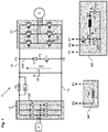
- a variable speed drive 1 comprises an input rectifier module 12 which is intended to rectify an AC voltage, for example three-phase, from an external power supply network A (for example a three-phase 380Vac electrical network).
- This rectifier module 12 advantageously uses diodes 120 which are more economical and more reliable than thyristors.
- This rectified voltage can be filtered to obtain a DC voltage Vdc (for example of the order of 200 to 800Vcc or more, depending on the conditions of use) applied to a continuous power supply bus consisting of a positive line 10 and a negative line 11.
- a bus capacitor Cb is usually used to keep constant the voltage Vdc of the DC bus.
- This bus capacitor Cb is connected between the positive line 10 and the negative line 11 of the bus and, in standard drives, it is generally electrolytic type.
- the variable speed drive 1 comprises at the output an inverter module 13 making it possible, from the DC bus, to control an electric load C with a variable voltage which may be of variable amplitude and frequency.
- the inverter module 13 uses for this purpose a Pulse Width Modulation (PWM) control for controlling electronic power switches 130 mounted on each phase. These switches are power transistors, for example of the IGBT type, controlled by a control unit (not shown) producing the PWM.
- PWM Pulse Width Modulation
- the inverter module 13 comprises three arms for supplying a three-phase variable voltage to the electrical load C, each arm being provided with two power transistors 130 in series between a positive terminal and a negative terminal of the power bus, for a total of six power transistors.
- a non-reversible stator speed controller also comprises a precharging circuit consisting of a precharge resistor Rp and a precharge relay RLp connected to the positive line of the DC supply bus or directly in series. with the bus capacitor Cb.
- a variable speed drive 1 may comprise a braking resistor Rf intended to dissipate the energy generated during braking of the electric charge or means for storing and regenerating the electrical energy generated during the braking of the electric charge.
- the storage and regeneration means of the electrical energy may then comprise one or more capacitors (s), more particularly of the super-capacitor (s) type UC (also called super-capacitance or ultra-capacitance).
- s super-capacitor
- a super-capacitor UC behaves like an electrochemical battery in that it is capable of storing a larger volume of electrical energy than a standard capacitor, but unlike an electrochemical battery, it behaves like a standard capacitor in that that it is able to withstand strong currents of charge and discharge.
- a braking resistor Rf or means for storing and regenerating the electrical energy requires the presence of a first switching arm 100 connected between the positive line 10 and the negative line 11 of the DC bus. supply, in parallel with the bus capacitor Cb and downstream thereof.
- This first switching arm 100 comprises at least a first controlled electronic switch T1, such as for example an IGBT type transistor, and for example a diode D1 connected in series with the electronic switch T1.
- the objective of the invention is therefore to be able to use this common part constituted by this first switching arm 100 and to propose to connect a first module M1 having a braking resistor Rf or a second module M2 comprising storage means and regenerating the electrical energy generated during the braking of the electric charge.
- a first module M1 having a braking resistor Rf or a second module M2 comprising storage means and regenerating the electrical energy generated during the braking of the electric charge.
- the module M1, M2 is removable, the user can choose to use a braking resistor Rf or storage and regeneration means of the electrical energy generated during the braking of the electric charge.
- the drive thus comprises a dedicated slot intended to connect the first module M1 or the second module M2 to the first switching arm 100.
- This slot comprises a first connection point P1 on the positive line 10 of the DC bus. supply, a second connection point P2 on the negative line 11 of the DC supply bus, and a third connection point P3 on the midpoint located between the diode D1 and the electronic switch T1 of the first switching arm 100.
- the first module M1 comprises a housing or cassette containing a braking resistor Rf intended to dissipate the electrical energy generated during the braking of the electric charge.
- the first module M1 is connected to the third connection point P3 and the first connection point P1 (in parallel with the diode D1).
- the second module M2 comprises a housing or cassette, preferably of identical shape to the cassette of the first module, enclosing a second switching arm 200 and electrical energy storage means composed of at least one super -capacitor UC.
- the second switching arm 200 comprises at least one second electronic switch T2, such as for example an IGBT type transistor, and for example a diode D2 connected in series with the second electronic switch T2.
- the second module M2 also comprises an inductance L connected in series with the supercapacitor UC, the assembly composed of this inductor L and the supercapacitor UC being connected in parallel with the diode D2 or the second electronic switch T2 of the second arm when the second module M2 is connected to the variable speed drive 1, the midpoint of connection P4 located between the electronic switch T2 and the diode D2 of the second switching arm 200 is connected to the third connection point P3 and the second switching arm 200 is connected on the one hand to the first connection point P1 and on the other hand to the second connection point P2 .
- the diode D2 is connected antiparallel to the first electronic switch T1 and the diode D1 is connected antiparallel to the second electronic switch T2.
- each module is for example in the form of an identical removable cassette intended to be connected to the drive controller.
- the variator comprises the control means for controlling each electronic switch T1, T2 employed, depending on whether the first module M1 or the second module M2 is connected.
- control means When the second module is connected, the control means may be common to the two switches T1, T2 employed. In this case, they will for example be located in the second module M2. Alternatively, the control means may comprise a separate control circuit for each switch T1, T2, one dedicated to the switch T1 being located in the drive and the other dedicated to the switch T2 located in the second module M2, the two circuits being then synchronized to control the two modes of operation of the variator.
- the electronic switch T1 is controlled in modulation (alternation of opening and closing), for example by MLI, and the electronic switch T2 is controlled at the opening so as to discharge the super- CPU capacitor on the DC power bus.
- the electronic switch T1 is controlled at the opening and the electronic switch T2 is controlled in modulation so as to transfer the excess energy generated during braking to the super-capacitor UC.
- the current values luc and / or voltage Vuc at the super-capacitor UC can of course be measured or estimated.
Description
La présente invention se rapporte à un variateur de vitesse comportant des moyens de stockage et de régénération de l'énergie électrique générée lors d'un freinage de la charge électrique. Ces moyens de stockage et de régénération comportent par exemple un ou plusieurs super-condensateurs, appelés également super-capacités ou ultra-capacités.The present invention relates to a speed controller comprising means for storing and regenerating the electrical energy generated during a braking of the electric charge. These storage and regeneration means comprise for example one or more supercapacitors, also called super-capacitors or ultra-capacitors.
De manière connue, un variateur de vitesse est connecté au réseau électrique d'alimentation et destiné à commander une charge électrique. Il comporte en entrée un module redresseur de tension qui génère une tension continue à partir d'une tension alternative fournie par le réseau et qui alimente en aval un bus continu d'alimentation doté d'une ligne positive et d'une ligne négative. Un condensateur de filtrage, appelé communément condensateur de bus, est monté entre une ligne positive et une ligne négative du bus continu. En sortie, le variateur comporte un module onduleur alimenté par le bus continu, permettant de générer, à partir de la tension continue, une tension variable qui peut être d'amplitude et de fréquence variables en utilisant des interrupteurs électroniques par exemple de type transistors IGBT commandés par Modulation à Largeur d'Impulsions (MLI ou PWM).In known manner, a variable speed drive is connected to the power supply network and intended to control an electrical load. It comprises as input a voltage rectifier module which generates a DC voltage from an AC voltage supplied by the network and which feeds downstream a DC supply bus having a positive line and a negative line. A filter capacitor, commonly referred to as a bus capacitor, is mounted between a positive line and a negative line of the DC bus. At the output, the drive comprises an inverter module powered by the DC bus, making it possible to generate, from the DC voltage, a variable voltage which can be of variable amplitude and frequency by using electronic switches, for example of the IGBT transistors type. controlled by Pulse Width Modulation (PWM or PWM).
Il est connu du document
Par ailleurs il est connu du brevet
Le but de l'invention est de proposer un variateur de vitesse dans lequel l'utilisateur peut choisir s'il souhaite une résistance de freinage ou une fonction de stockage et de régénération d'énergie, sans ajouter de coût supplémentaire au produit.The object of the invention is to propose a variable speed drive in which the user can choose whether he wants a braking resistor or a storage and regeneration of energy function, without adding additional cost to the product.
Ce but est atteint par un variateur de vitesse comportant :
- un bus continu d'alimentation de puissance doté d'une ligne positive et d'une ligne négative,
- un condensateur de bus connecté entre la ligne positive et la ligne négative du bus continu d'alimentation,
- un module onduleur alimenté par le bus continu d'alimentation et commandé pour délivrer une tension variable à une charge électrique (C),
- un premier bras de commutation connecté entre la ligne positive et la ligne négative du bus et comportant au moins un premier interrupteur électronique,
- un premier module comportant une résistance de freinage ou un deuxième module comportant des moyens de stockage et de régénération de l'énergie électrique générée lors du freinage de la charge électrique,
- le premier module et le deuxième module étant amovibles et interchangeables,
- le premier module et le deuxième module se présentant sous la forme d'une cassette venant se connecter d'une part sur le bus continu d'alimentation et d'autre part sur le premier bras de commutation.
- a continuous power supply bus with a positive line and a negative line,
- a bus capacitor connected between the positive line and the negative line of the DC bus,
- an inverter module powered by the DC supply bus and controlled to deliver a variable voltage to an electrical load (C),
- a first switching arm connected between the positive line and the negative line of the bus and comprising at least a first electronic switch,
- a first module comprising a braking resistor or a second module comprising means for storing and regenerating the electrical energy generated during braking of the electric charge,
- the first module and the second module being removable and interchangeable,
- the first module and the second module being in the form of a cassette coming to connect on the one hand on the DC bus and on the other hand on the first switching arm.
Selon une particularité, le premier bras de commutation comporte une diode montée en série avec le premier interrupteur électronique et définissant entre eux un point milieu de connexion.According to one feature, the first switching arm comprises a diode connected in series with the first electronic switch and defining between them a connection midpoint.
Selon une autre particularité, le deuxième module comporte un deuxième bras de commutation et un ou plusieurs super-condensateur(s).According to another feature, the second module comprises a second switching arm and one or more super-capacitors (s).
Selon une autre particularité, le deuxième bras de commutation est connecté en parallèle du premier bras de commutation.According to another feature, the second switching arm is connected in parallel with the first switching arm.
Selon une autre particularité, le deuxième bras de commutation comporte un deuxième interrupteur électronique et une diode connectés en série et définissant un point milieu de connexion connecté au point milieu de connexion du premier bras de commutation, ladite diode du deuxième bras de commutation étant connectée en antiparallèle avec le premier interrupteur électronique et la diode du premier bras de commutation étant connectée en antiparallèle du deuxième interrupteur électronique.According to another feature, the second switching arm comprises a second electronic switch and a diode connected in series and defining a connection midpoint connected to the connection point of the first switching arm, said diode of the second switching arm being connected in antiparallel with the first electronic switch and the diode of the first switching arm being connected in antiparallel of the second electronic switch.
Selon une autre particularité, le deuxième module comporte une inductance connectée en série avec le super-condensateur.According to another particularity, the second module comprises an inductance connected in series with the super-capacitor.
Selon une autre particularité, la résistance de freinage du premier module est connectée en parallèle de la diode du premier bras de commutation.According to another feature, the braking resistor of the first module is connected in parallel with the diode of the first switching arm.
Selon une autre particularité, le variateur de vitesse comporte des moyens de commande agencés pour fonctionner différemment selon que le premier module ou le deuxième module est connecté.According to another particularity, the variable speed drive comprises control means arranged to operate differently depending on whether the first module or the second module is connected.
D'autres caractéristiques et avantages vont apparaître dans la description détaillée qui suit en se référant à un mode de réalisation donné à titre d'exemple et représenté par la
En référence à la
Le variateur de vitesse 1 comporte en sortie un module onduleur 13 permettant, à partir du bus continu, de commander une charge électrique C avec une tension variable qui peut être d'amplitude et de fréquence variables. Le module onduleur 13 utilise pour cela une commande par Modulation à Largeur d'Impulsions (MLI ou PWM) pour commander des interrupteurs électroniques de puissance 130 montés sur chaque phase. Ces interrupteurs sont des transistors de puissance, par exemple de type IGBT, commandés par une unité de commande (non représentée) réalisant la MLI. Sur la
En règle générale, un variateur de vitesse à redresseur non réversible comporte également un circuit de précharge composé d'une résistance de précharge Rp et d'un relais de précharge RLp connecté sur la ligne positive 10 du bus continu d'alimentation ou directement en série avec le condensateur de bus Cb.As a general rule, a non-reversible stator speed controller also comprises a precharging circuit consisting of a precharge resistor Rp and a precharge relay RLp connected to the positive line of the DC supply bus or directly in series. with the bus capacitor Cb.
Par ailleurs, un variateur de vitesse 1 peut comporter une résistance de freinage Rf destinée à dissiper l'énergie générée lors du freinage de la charge électrique ou des moyens de stockage et de régénération de l'énergie électrique générée lors du freinage de la charge électrique C. Les moyens de stockage et de régénération de l'énergie électrique peuvent alors comporter un ou plusieurs condensateur(s), plus particulièrement du type super-condensateur(s) UC (appelé également super-capacité ou ultra-capacité). Un super-condensateur UC se comporte comme une batterie électrochimique en ce qu'il est capable de stocker un volume d'énergie électrique plus important qu'un condensateur standard, mais contrairement à une batterie électrochimique, il se comporte comme un condensateur standard en ce qu'il est capable de supporter de forts courants de charge et de décharge.Moreover, a variable speed drive 1 may comprise a braking resistor Rf intended to dissipate the energy generated during braking of the electric charge or means for storing and regenerating the electrical energy generated during the braking of the electric charge. C. The storage and regeneration means of the electrical energy may then comprise one or more capacitors (s), more particularly of the super-capacitor (s) type UC (also called super-capacitance or ultra-capacitance). A super-capacitor UC behaves like an electrochemical battery in that it is capable of storing a larger volume of electrical energy than a standard capacitor, but unlike an electrochemical battery, it behaves like a standard capacitor in that that it is able to withstand strong currents of charge and discharge.
L'emploi d'une résistance de freinage Rf ou de moyens de stockage et de régénération de l'énergie électrique nécessite la présence d'un premier bras de commutation 100 connecté entre la ligne positive 10 et la ligne négative 11 du bus continu d'alimentation, en parallèle du condensateur de bus Cb et en aval de celui-ci. Ce premier bras de commutation 100 comporte au moins un premier interrupteur électronique T1 commandé, tel que par exemple un transistor de type IGBT, et par exemple une diode D1 connectée en série avec l'interrupteur électronique T1.The use of a braking resistor Rf or means for storing and regenerating the electrical energy requires the presence of a
L'objectif de l'invention est donc de pouvoir utiliser cette partie commune constituée par ce premier bras de commutation 100 et de proposer d'y connecter un premier module M1 comportant une résistance de freinage Rf ou un deuxième module M2 comportant des moyens de stockage et de régénération de l'énergie électrique générée lors du freinage de la charge électrique. Selon l'invention, comme le module M1, M2 est amovible, l'utilisateur peut choisir d'employer une résistance de freinage Rf ou des moyens de stockage et de régénération de l'énergie électrique générée lors du freinage de la charge électrique.The objective of the invention is therefore to be able to use this common part constituted by this
Selon l'invention, le variateur comporte ainsi un emplacement dédié destiné à connecter le premier module M1 ou le deuxième module M2 au premier bras de commutation 100. Cet emplacement comporte un premier point de connexion P1 sur la ligne positive 10 du bus continu d'alimentation, un deuxième point de connexion P2 sur la ligne négative 11 du bus continu d'alimentation, et un troisième point de connexion P3 sur le point milieu situé entre la diode D1 et l'interrupteur électronique T1 du premier bras de commutation 100.According to the invention, the drive thus comprises a dedicated slot intended to connect the first module M1 or the second module M2 to the
Selon l'invention, le premier module M1 comporte un boîtier ou cassette renfermant une résistance de freinage Rf destinée à dissiper l'énergie électrique générée lors du freinage de la charge électrique. Lorsqu'il est en place, le premier module M1 vient se connecter sur le troisième point de connexion P3 et sur le premier point de connexion P1 (en parallèle de la diode D1).According to the invention, the first module M1 comprises a housing or cassette containing a braking resistor Rf intended to dissipate the electrical energy generated during the braking of the electric charge. When in place, the first module M1 is connected to the third connection point P3 and the first connection point P1 (in parallel with the diode D1).
Selon l'invention, le deuxième module M2 comporte un boîtier ou cassette, préférentiellement de forme identique à la cassette du premier module, renfermant un deuxième bras de commutation 200 et des moyens de stockage de l'énergie électrique composés d'au moins un super-condensateur UC. Le second bras de commutation 200 comporte au moins un deuxième interrupteur électronique T2, tel que par exemple un transistor de type IGBT, et par exemple une diode D2 connectée en série avec le deuxième interrupteur électronique T2. Le deuxième module M2 comporte également une inductance L connectée en série avec le super-condensateur UC, l'ensemble composé de cette inductance L et du super-condensateur UC étant connecté en parallèle de la diode D2 ou du deuxième interrupteur électronique T2 du deuxième bras de commutation 200. Lorsque le deuxième module M2 est connecté au variateur de vitesse 1, le point milieu de connexion P4 situé entre l'interrupteur électronique T2 et la diode D2 du deuxième bras de commutation 200 est connecté au troisième point de connexion P3 et le deuxième bras de commutation 200 est connecté d'une part sur le premier point de connexion P1 et d'autre part sur le deuxième point de connexion P2. De cette manière, la diode D2 se trouve connectée en antiparallèle du premier interrupteur électronique T1 et la diode D1 se trouve connectée en antiparallèle du deuxième interrupteur électronique T2.According to the invention, the second module M2 comprises a housing or cassette, preferably of identical shape to the cassette of the first module, enclosing a
Selon l'invention, chaque module se présente par exemple sous la forme d'une cassette amovible identique destinée à venir se connecter sur le variateur de vitesse.According to the invention, each module is for example in the form of an identical removable cassette intended to be connected to the drive controller.
Selon l'invention, le variateur comporte les moyens de commande permettant de commander chaque interrupteur électronique T1, T2 employé, selon que le premier module M1 ou le deuxième module M2 est connecté.According to the invention, the variator comprises the control means for controlling each electronic switch T1, T2 employed, depending on whether the first module M1 or the second module M2 is connected.
Lorsque le deuxième module est connecté, les moyens de commande peuvent être communs aux deux interrupteurs T1, T2 employés. Dans ce cas, ils seront par exemple localisés dans le deuxième module M2. En variante, les moyens de commande peuvent comporter un circuit de commande distinct pour chaque interrupteur T1, T2, l'un dédié à l'interrupteur T1 étant situé dans le variateur et l'autre dédié à l'interrupteur T2 situé dans le deuxième module M2, les deux circuits étant alors synchronisés pour commander les deux modes de fonctionnement du variateur.When the second module is connected, the control means may be common to the two switches T1, T2 employed. In this case, they will for example be located in the second module M2. Alternatively, the control means may comprise a separate control circuit for each switch T1, T2, one dedicated to the switch T1 being located in the drive and the other dedicated to the switch T2 located in the second module M2, the two circuits being then synchronized to control the two modes of operation of the variator.
Lorsque le deuxième module est connecté sur le variateur, deux modes de fonctionnement sont possibles, commandés en employant les interrupteurs électroniques T1, T2 du premier bras de commutation et du deuxième bras de commutation.When the second module is connected to the drive, two modes of operation are possible, controlled by using the electronic switches T1, T2 of the first switching arm and the second switching arm.
Dans un premier mode de fonctionnement, l'interrupteur électronique T1 est commandé en modulation (alternance d'ouverture et de fermeture), par exemple par MLI, et l'interrupteur électronique T2 est commandé à l'ouverture de manière à décharger le super-condensateur UC sur le bus continu d'alimentation.In a first mode of operation, the electronic switch T1 is controlled in modulation (alternation of opening and closing), for example by MLI, and the electronic switch T2 is controlled at the opening so as to discharge the super- CPU capacitor on the DC power bus.
Dans un deuxième mode de fonctionnement, l'interrupteur électronique T1 est commandé à l'ouverture et l'interrupteur électronique T2 est commandé en modulation de manière à transférer l'énergie excédante générée lors du freinage vers le super-condensateur UC.In a second mode of operation, the electronic switch T1 is controlled at the opening and the electronic switch T2 is controlled in modulation so as to transfer the excess energy generated during braking to the super-capacitor UC.
Pour mettre en place les deux modes de fonctionnement précités, les valeurs de courant luc et/ou de tension Vuc au niveau du super-condensateur UC peuvent bien entendu être mesurées ou estimées.To set up the two operating modes mentioned above, the current values luc and / or voltage Vuc at the super-capacitor UC can of course be measured or estimated.
Bien entendu, d'autres variantes de réalisation peuvent être envisagées, le principe restant de pouvoir utiliser un même bras de commutation et d'y adjoindre un module doté d'une résistance de freinage ou de moyens de stockage et de régénération de l'énergie électrique générée lors du freinage.Of course, other variants of embodiment can be envisaged, the principle remaining to be able to use the same switching arm and to add a module with a braking resistor or means for storage and regeneration of energy generated during braking.
Il est bien entendu que l'on peut, sans sortir du cadre de l'invention, imaginer d'autres variantes et perfectionnements de détail et de même envisager l'emploi de moyens équivalents.It is understood that one can, without departing from the scope of the invention, imagine other variants and refinements of detail and even consider the use of equivalent means.
Claims (8)
- A variable-speed drive (1) comprising:- a DC power supply bus provided with a positive line (10) and a negative line (11),- a bus capacitor (Cb) connected between the positive line (10) and the negative line (11) of the DC power supply bus,- an inverter module (13) powered by the DC power supply bus and controlled to deliver a variable voltage to an electrical load (C),- a first switching leg (100) connected between the positive line (10) and the negative line (11) of the bus and comprising at least one first electronic switch (T1),said variable-speed drive being characterized in that it also comprises:- a first module (M1) comprising a braking resistor or a second module (M2) comprising means for storing and regenerating electrical energy generated during the braking of the electrical load (C), in that- the first module and the second module are removable and interchangeable,
and characterized in that- the first module and the second module take the form of a cassette that connects on the one hand to the DC power supply bus and on the other hand to the first switching leg (100). - The variable-speed drive as claimed in claim 1, characterized in that the first switching leg (100) comprises a diode (D1) mounted in series with the first electronic switch (T1) and defining between them a connection mid-point (P3).
- The variable-speed drive as claimed in claim 2, characterized in that the second module comprises a second switching leg (200) and one or more supercapacitors (UC).
- The variable-speed drive as claimed in claim 3, characterized in that the second switching leg (200) is connected in parallel with the first switching leg (100) .
- The variable-speed drive as claimed in claim 4, characterized in that the second switching leg comprises a second electronic switch (T2) and a diode (D2) connected in series and defining a connection mid-point (P4) connected to the connection mid-point (P3) of the first switching leg (100), said diode (D2) of the second switching leg being connected in antiparallel with the first electronic switch (T1) and the diode (D1) of the first switching leg being connected in antiparallel with the second electronic switch (T2).
- The variable-speed drive as claimed in claim 4, characterized in that the second module comprises an inductor (L) connected in series with the supercapacitor (UC).
- The variable-speed drive as claimed in claim 2, characterized in that the braking resistor (Rf) of the first module (M1) is connected in parallel with the diode (D1) of the first switching leg (100).
- The variable-speed drive as claimed in one of claims 1 to 7, characterized in that it comprises control means arranged to operate differently depending on whether the first module (M1) or the second module (M2) is connected.
Applications Claiming Priority (2)
| Application Number | Priority Date | Filing Date | Title |
|---|---|---|---|
| FR1059357A FR2967532B1 (en) | 2010-11-15 | 2010-11-15 | SPEED DRIVE WITH SUPER-CAPACITOR MODULE |
| PCT/EP2011/068452 WO2012065806A1 (en) | 2010-11-15 | 2011-10-21 | Variable-speed drive provided with a supercapacitor module |
Publications (2)
| Publication Number | Publication Date |
|---|---|
| EP2641323A1 EP2641323A1 (en) | 2013-09-25 |
| EP2641323B1 true EP2641323B1 (en) | 2018-02-21 |
Family
ID=44317461
Family Applications (1)
| Application Number | Title | Priority Date | Filing Date |
|---|---|---|---|
| EP11772984.8A Active EP2641323B1 (en) | 2010-11-15 | 2011-10-21 | Variable-speed drive provided with a supercapacitor module |
Country Status (8)
| Country | Link |
|---|---|
| US (1) | US9270192B2 (en) |
| EP (1) | EP2641323B1 (en) |
| JP (1) | JP5717865B2 (en) |
| CN (1) | CN103222182A (en) |
| BR (1) | BR112013009268B1 (en) |
| ES (1) | ES2664498T3 (en) |
| FR (1) | FR2967532B1 (en) |
| WO (1) | WO2012065806A1 (en) |
Families Citing this family (8)
| Publication number | Priority date | Publication date | Assignee | Title |
|---|---|---|---|---|
| ES2564011T3 (en) * | 2010-10-22 | 2016-03-17 | Tld (Canada) Inc. | Power management system |
| TWI450491B (en) * | 2012-05-09 | 2014-08-21 | Delta Electronics Inc | Motor driving device for protecting inrush current |
| CN103532365B (en) * | 2013-10-25 | 2016-05-25 | 苏州汇川技术有限公司 | A kind of brake unit |
| EP3156358A4 (en) * | 2015-08-07 | 2017-12-13 | Forward Electronics Company Limited | Elevator automatic rescue and energy-saving device and control method for same and super capacitor module |
| ES2893752T3 (en) | 2017-02-22 | 2022-02-10 | Otis Elevator Co | Power control system for a battery-powered elevator |
| FR3092451B1 (en) * | 2019-02-01 | 2021-01-29 | Commissariat Energie Atomique | Power converter comprising at least one normally closed transistor |
| DE102020003119A1 (en) * | 2019-05-29 | 2020-12-03 | Sew-Eurodrive Gmbh & Co Kg | Propulsion system and method for operating a propulsion system |
| US11811331B2 (en) | 2020-10-30 | 2023-11-07 | Velocity Magnetics, Inc. | Insulated-gate bipolar transistor (IGBT) rectifier for charging ultra-capacitors |
Family Cites Families (21)
| Publication number | Priority date | Publication date | Assignee | Title |
|---|---|---|---|---|
| JP2656684B2 (en) * | 1991-06-12 | 1997-09-24 | 三菱電機株式会社 | Elevator blackout operation device |
| JPH0866056A (en) * | 1994-08-24 | 1996-03-08 | Mitsubishi Electric Corp | Inverter apparatus |
| JPH10155298A (en) * | 1996-11-22 | 1998-06-09 | Sanyo Denki Co Ltd | Electric motor controlling device and regenerative power processing circuit |
| EP1268335B1 (en) | 2000-03-31 | 2008-11-19 | Inventio Ag | Device and method for reducing the power of the supply connection in lift systems |
| EP1272418B1 (en) * | 2000-03-31 | 2008-11-19 | Inventio Ag | Emergency power supply device for lift systems |
| KR100509146B1 (en) * | 2001-10-17 | 2005-08-18 | 미쓰비시덴키 가부시키가이샤 | Elevator controller |
| JP4544884B2 (en) * | 2004-03-18 | 2010-09-15 | 東芝エレベータ株式会社 | Elevator control device |
| US8172042B2 (en) | 2005-10-07 | 2012-05-08 | Otis Elevator Company | Elevator power system |
| FI120665B (en) * | 2007-06-20 | 2010-01-15 | Kone Corp | Power control of the transport system |
| CN201058578Y (en) * | 2007-06-29 | 2008-05-14 | 合肥工业大学 | Electric vehicle power source with fuel cell mixed super capacitor |
| CN201086642Y (en) * | 2007-09-10 | 2008-07-16 | 株洲联诚集团有限责任公司 | Braking resistor device with convenient maintenance used for railway locomotive and subway vehicle |
| FR2932327B1 (en) | 2008-06-05 | 2010-06-04 | Schneider Toshiba Inverter | SPEED DRIVE WITH SUPER CAPACITOR |
| US20100039054A1 (en) * | 2008-08-14 | 2010-02-18 | General Electric Company | Vehicle, system and method |
| CN201266838Y (en) * | 2008-09-19 | 2009-07-01 | 宝鸡石油机械有限责任公司 | Drill/service rig power system with DC bus bar power supply |
| CN101728999B (en) * | 2008-10-10 | 2012-05-30 | 鸿富锦精密工业(深圳)有限公司 | Motor driving device |
| JP5503864B2 (en) * | 2008-10-20 | 2014-05-28 | 株式会社日立産機システム | Power semiconductor module |
| JP5293390B2 (en) * | 2009-05-08 | 2013-09-18 | コニカミノルタ株式会社 | Power supply control apparatus and image forming apparatus |
| CN201504218U (en) * | 2009-09-11 | 2010-06-09 | 刘培 | Power-saving frequency converter for elevators |
| FR2977996B1 (en) | 2011-07-13 | 2013-07-12 | Schneider Toshiba Inverter | POWER CONVERTER COMPRISING A NORMALLY CLOSED FIELD EFFECT TRANSISTOR INVERTER MODULE |
| US9120390B2 (en) * | 2012-03-08 | 2015-09-01 | General Electric Company | Apparatus for transferring energy using onboard power electronics and method of manufacturing same |
| US9013168B2 (en) * | 2012-06-07 | 2015-04-21 | General Electric Company | System for transferring energy from an energy source and method of making same |
-
2010
- 2010-11-15 FR FR1059357A patent/FR2967532B1/en not_active Expired - Fee Related
-
2011
- 2011-10-21 ES ES11772984.8T patent/ES2664498T3/en active Active
- 2011-10-21 US US13/879,536 patent/US9270192B2/en active Active
- 2011-10-21 CN CN2011800548754A patent/CN103222182A/en active Pending
- 2011-10-21 BR BR112013009268-8A patent/BR112013009268B1/en active IP Right Grant
- 2011-10-21 JP JP2013538117A patent/JP5717865B2/en active Active
- 2011-10-21 EP EP11772984.8A patent/EP2641323B1/en active Active
- 2011-10-21 WO PCT/EP2011/068452 patent/WO2012065806A1/en active Application Filing
Also Published As
| Publication number | Publication date |
|---|---|
| CN103222182A (en) | 2013-07-24 |
| WO2012065806A1 (en) | 2012-05-24 |
| ES2664498T3 (en) | 2018-04-19 |
| FR2967532A1 (en) | 2012-05-18 |
| BR112013009268A2 (en) | 2016-07-26 |
| JP5717865B2 (en) | 2015-05-13 |
| FR2967532B1 (en) | 2012-11-16 |
| BR112013009268B1 (en) | 2020-05-26 |
| JP2013544066A (en) | 2013-12-09 |
| US20130201732A1 (en) | 2013-08-08 |
| US9270192B2 (en) | 2016-02-23 |
| EP2641323A1 (en) | 2013-09-25 |
Similar Documents
| Publication | Publication Date | Title |
|---|---|---|
| EP2641323B1 (en) | Variable-speed drive provided with a supercapacitor module | |
| EP3554887B1 (en) | Control method for a charge device embedded on an electrical or hybrid vehicle | |
| EP2859651B1 (en) | Absorption circuit for absorbing a power ripple and associated method | |
| EP2887527B1 (en) | Compact and modular electric power supply with multiple converters, in particular for quick charging terminals for electric vehicles | |
| FR2893787A1 (en) | POWER FACTOR CORRECTION DEVICE FOR SPEED DRIVE | |
| EP2338225B1 (en) | Energy recovery device in a variable-frequency drive | |
| EP2281337B1 (en) | Method for recovering power in a variable speed drive | |
| EP2727206B1 (en) | Power management system comprising a power source, a source of renewable energy, and a power converter | |
| EP2815493B1 (en) | Ac/dc electrical conversion device permitting energy recovery and management of dc-side short-circuits and control method thereof | |
| EP3539204B1 (en) | Method for controlling a three-phase rectifier for a charging device on board an electric or hybrid vehicle | |
| FR2982719A1 (en) | POWER CONVERTER HAVING MULTIPLE CONTROLLED CURRENT SOURCES CONNECTED IN PARALLEL | |
| FR3011400A1 (en) | SYSTEM AND METHOD FOR CHARGING A TRACTION BATTERY CURRENT CALLING CURRENT CAPACITIES PARASITES | |
| EP3539203B1 (en) | Method for controlling a three-phase rectifier for a charging device on board an electrical or hybrid vehicle | |
| WO2012084389A2 (en) | Power converter equipped at the output with a filtering device | |
| Bansal et al. | A new single stage AC-DC high step-down bifolding converter with synchronous rectification and 2nd harmonic mitigation for onboard eV chargers | |
| FR2903248A1 (en) | ELECTRIC CONVERSION DEVICE, CONVERTER AND ELECTRICAL SUPPLY WITHOUT INTERRUPTION COMPRISING SUCH A DEVICE | |
| EP3707800A1 (en) | Method for controlling a battery charger for electrical accumulators | |
| EP2131483B1 (en) | Speed regulator with super capacitor | |
| WO2012084572A2 (en) | Ac/dc power converter with improved power factor and improved thdi | |
| WO2013120727A1 (en) | Module for the regeneration of electrical energy for a speed variator | |
| FR2974462A1 (en) | Device for charging storage unit i.e. rechargeable high voltage battery, for electric vehicle, has power factor correction module connected to connection terminals and power supply during charging phase of storage unit |
Legal Events
| Date | Code | Title | Description |
|---|---|---|---|
| PUAI | Public reference made under article 153(3) epc to a published international application that has entered the european phase |
Free format text: ORIGINAL CODE: 0009012 |
|
| 17P | Request for examination filed |
Effective date: 20130410 |
|
| AK | Designated contracting states |
Kind code of ref document: A1 Designated state(s): AL AT BE BG CH CY CZ DE DK EE ES FI FR GB GR HR HU IE IS IT LI LT LU LV MC MK MT NL NO PL PT RO RS SE SI SK SM TR |
|
| DAX | Request for extension of the european patent (deleted) | ||
| GRAP | Despatch of communication of intention to grant a patent |
Free format text: ORIGINAL CODE: EPIDOSNIGR1 |
|
| INTG | Intention to grant announced |
Effective date: 20171127 |
|
| GRAS | Grant fee paid |
Free format text: ORIGINAL CODE: EPIDOSNIGR3 |
|
| GRAA | (expected) grant |
Free format text: ORIGINAL CODE: 0009210 |
|
| AK | Designated contracting states |
Kind code of ref document: B1 Designated state(s): AL AT BE BG CH CY CZ DE DK EE ES FI FR GB GR HR HU IE IS IT LI LT LU LV MC MK MT NL NO PL PT RO RS SE SI SK SM TR |
|
| REG | Reference to a national code |
Ref country code: GB Ref legal event code: FG4D Free format text: NOT ENGLISH |
|
| REG | Reference to a national code |
Ref country code: CH Ref legal event code: EP |
|
| REG | Reference to a national code |
Ref country code: AT Ref legal event code: REF Ref document number: 972748 Country of ref document: AT Kind code of ref document: T Effective date: 20180315 |
|
| REG | Reference to a national code |
Ref country code: IE Ref legal event code: FG4D Free format text: LANGUAGE OF EP DOCUMENT: FRENCH |
|
| REG | Reference to a national code |
Ref country code: DE Ref legal event code: R096 Ref document number: 602011045814 Country of ref document: DE |
|
| REG | Reference to a national code |
Ref country code: ES Ref legal event code: FG2A Ref document number: 2664498 Country of ref document: ES Kind code of ref document: T3 Effective date: 20180419 |
|
| REG | Reference to a national code |
Ref country code: NL Ref legal event code: MP Effective date: 20180221 |
|
| REG | Reference to a national code |
Ref country code: LT Ref legal event code: MG4D |
|
| REG | Reference to a national code |
Ref country code: AT Ref legal event code: MK05 Ref document number: 972748 Country of ref document: AT Kind code of ref document: T Effective date: 20180221 |
|
| PG25 | Lapsed in a contracting state [announced via postgrant information from national office to epo] |
Ref country code: FI Free format text: LAPSE BECAUSE OF FAILURE TO SUBMIT A TRANSLATION OF THE DESCRIPTION OR TO PAY THE FEE WITHIN THE PRESCRIBED TIME-LIMIT Effective date: 20180221 Ref country code: CY Free format text: LAPSE BECAUSE OF FAILURE TO SUBMIT A TRANSLATION OF THE DESCRIPTION OR TO PAY THE FEE WITHIN THE PRESCRIBED TIME-LIMIT Effective date: 20180221 Ref country code: LT Free format text: LAPSE BECAUSE OF FAILURE TO SUBMIT A TRANSLATION OF THE DESCRIPTION OR TO PAY THE FEE WITHIN THE PRESCRIBED TIME-LIMIT Effective date: 20180221 Ref country code: NL Free format text: LAPSE BECAUSE OF FAILURE TO SUBMIT A TRANSLATION OF THE DESCRIPTION OR TO PAY THE FEE WITHIN THE PRESCRIBED TIME-LIMIT Effective date: 20180221 Ref country code: NO Free format text: LAPSE BECAUSE OF FAILURE TO SUBMIT A TRANSLATION OF THE DESCRIPTION OR TO PAY THE FEE WITHIN THE PRESCRIBED TIME-LIMIT Effective date: 20180521 Ref country code: HR Free format text: LAPSE BECAUSE OF FAILURE TO SUBMIT A TRANSLATION OF THE DESCRIPTION OR TO PAY THE FEE WITHIN THE PRESCRIBED TIME-LIMIT Effective date: 20180221 |
|
| PG25 | Lapsed in a contracting state [announced via postgrant information from national office to epo] |
Ref country code: BG Free format text: LAPSE BECAUSE OF FAILURE TO SUBMIT A TRANSLATION OF THE DESCRIPTION OR TO PAY THE FEE WITHIN THE PRESCRIBED TIME-LIMIT Effective date: 20180521 Ref country code: RS Free format text: LAPSE BECAUSE OF FAILURE TO SUBMIT A TRANSLATION OF THE DESCRIPTION OR TO PAY THE FEE WITHIN THE PRESCRIBED TIME-LIMIT Effective date: 20180221 Ref country code: AT Free format text: LAPSE BECAUSE OF FAILURE TO SUBMIT A TRANSLATION OF THE DESCRIPTION OR TO PAY THE FEE WITHIN THE PRESCRIBED TIME-LIMIT Effective date: 20180221 Ref country code: SE Free format text: LAPSE BECAUSE OF FAILURE TO SUBMIT A TRANSLATION OF THE DESCRIPTION OR TO PAY THE FEE WITHIN THE PRESCRIBED TIME-LIMIT Effective date: 20180221 Ref country code: LV Free format text: LAPSE BECAUSE OF FAILURE TO SUBMIT A TRANSLATION OF THE DESCRIPTION OR TO PAY THE FEE WITHIN THE PRESCRIBED TIME-LIMIT Effective date: 20180221 Ref country code: GR Free format text: LAPSE BECAUSE OF FAILURE TO SUBMIT A TRANSLATION OF THE DESCRIPTION OR TO PAY THE FEE WITHIN THE PRESCRIBED TIME-LIMIT Effective date: 20180522 |
|
| REG | Reference to a national code |
Ref country code: FR Ref legal event code: PLFP Year of fee payment: 8 |
|
| PG25 | Lapsed in a contracting state [announced via postgrant information from national office to epo] |
Ref country code: MT Free format text: LAPSE BECAUSE OF FAILURE TO SUBMIT A TRANSLATION OF THE DESCRIPTION OR TO PAY THE FEE WITHIN THE PRESCRIBED TIME-LIMIT Effective date: 20180221 |
|
| PG25 | Lapsed in a contracting state [announced via postgrant information from national office to epo] |
Ref country code: PL Free format text: LAPSE BECAUSE OF FAILURE TO SUBMIT A TRANSLATION OF THE DESCRIPTION OR TO PAY THE FEE WITHIN THE PRESCRIBED TIME-LIMIT Effective date: 20180221 Ref country code: EE Free format text: LAPSE BECAUSE OF FAILURE TO SUBMIT A TRANSLATION OF THE DESCRIPTION OR TO PAY THE FEE WITHIN THE PRESCRIBED TIME-LIMIT Effective date: 20180221 Ref country code: RO Free format text: LAPSE BECAUSE OF FAILURE TO SUBMIT A TRANSLATION OF THE DESCRIPTION OR TO PAY THE FEE WITHIN THE PRESCRIBED TIME-LIMIT Effective date: 20180221 Ref country code: AL Free format text: LAPSE BECAUSE OF FAILURE TO SUBMIT A TRANSLATION OF THE DESCRIPTION OR TO PAY THE FEE WITHIN THE PRESCRIBED TIME-LIMIT Effective date: 20180221 |
|
| REG | Reference to a national code |
Ref country code: DE Ref legal event code: R097 Ref document number: 602011045814 Country of ref document: DE |
|
| PG25 | Lapsed in a contracting state [announced via postgrant information from national office to epo] |
Ref country code: DK Free format text: LAPSE BECAUSE OF FAILURE TO SUBMIT A TRANSLATION OF THE DESCRIPTION OR TO PAY THE FEE WITHIN THE PRESCRIBED TIME-LIMIT Effective date: 20180221 Ref country code: SK Free format text: LAPSE BECAUSE OF FAILURE TO SUBMIT A TRANSLATION OF THE DESCRIPTION OR TO PAY THE FEE WITHIN THE PRESCRIBED TIME-LIMIT Effective date: 20180221 Ref country code: SM Free format text: LAPSE BECAUSE OF FAILURE TO SUBMIT A TRANSLATION OF THE DESCRIPTION OR TO PAY THE FEE WITHIN THE PRESCRIBED TIME-LIMIT Effective date: 20180221 Ref country code: CZ Free format text: LAPSE BECAUSE OF FAILURE TO SUBMIT A TRANSLATION OF THE DESCRIPTION OR TO PAY THE FEE WITHIN THE PRESCRIBED TIME-LIMIT Effective date: 20180221 |
|
| PLBE | No opposition filed within time limit |
Free format text: ORIGINAL CODE: 0009261 |
|
| STAA | Information on the status of an ep patent application or granted ep patent |
Free format text: STATUS: NO OPPOSITION FILED WITHIN TIME LIMIT |
|
| 26N | No opposition filed |
Effective date: 20181122 |
|
| PG25 | Lapsed in a contracting state [announced via postgrant information from national office to epo] |
Ref country code: SI Free format text: LAPSE BECAUSE OF FAILURE TO SUBMIT A TRANSLATION OF THE DESCRIPTION OR TO PAY THE FEE WITHIN THE PRESCRIBED TIME-LIMIT Effective date: 20180221 |
|
| REG | Reference to a national code |
Ref country code: CH Ref legal event code: PL |
|
| REG | Reference to a national code |
Ref country code: BE Ref legal event code: MM Effective date: 20181031 |
|
| PG25 | Lapsed in a contracting state [announced via postgrant information from national office to epo] |
Ref country code: MC Free format text: LAPSE BECAUSE OF FAILURE TO SUBMIT A TRANSLATION OF THE DESCRIPTION OR TO PAY THE FEE WITHIN THE PRESCRIBED TIME-LIMIT Effective date: 20180221 Ref country code: LU Free format text: LAPSE BECAUSE OF NON-PAYMENT OF DUE FEES Effective date: 20181021 |
|
| REG | Reference to a national code |
Ref country code: IE Ref legal event code: MM4A |
|
| PG25 | Lapsed in a contracting state [announced via postgrant information from national office to epo] |
Ref country code: CH Free format text: LAPSE BECAUSE OF NON-PAYMENT OF DUE FEES Effective date: 20181031 Ref country code: BE Free format text: LAPSE BECAUSE OF NON-PAYMENT OF DUE FEES Effective date: 20181031 Ref country code: LI Free format text: LAPSE BECAUSE OF NON-PAYMENT OF DUE FEES Effective date: 20181031 |
|
| PG25 | Lapsed in a contracting state [announced via postgrant information from national office to epo] |
Ref country code: IE Free format text: LAPSE BECAUSE OF NON-PAYMENT OF DUE FEES Effective date: 20181021 |
|
| PG25 | Lapsed in a contracting state [announced via postgrant information from national office to epo] |
Ref country code: TR Free format text: LAPSE BECAUSE OF FAILURE TO SUBMIT A TRANSLATION OF THE DESCRIPTION OR TO PAY THE FEE WITHIN THE PRESCRIBED TIME-LIMIT Effective date: 20180221 |
|
| PG25 | Lapsed in a contracting state [announced via postgrant information from national office to epo] |
Ref country code: PT Free format text: LAPSE BECAUSE OF FAILURE TO SUBMIT A TRANSLATION OF THE DESCRIPTION OR TO PAY THE FEE WITHIN THE PRESCRIBED TIME-LIMIT Effective date: 20180221 |
|
| PG25 | Lapsed in a contracting state [announced via postgrant information from national office to epo] |
Ref country code: HU Free format text: LAPSE BECAUSE OF FAILURE TO SUBMIT A TRANSLATION OF THE DESCRIPTION OR TO PAY THE FEE WITHIN THE PRESCRIBED TIME-LIMIT; INVALID AB INITIO Effective date: 20111021 Ref country code: MK Free format text: LAPSE BECAUSE OF NON-PAYMENT OF DUE FEES Effective date: 20180221 |
|
| PG25 | Lapsed in a contracting state [announced via postgrant information from national office to epo] |
Ref country code: IS Free format text: LAPSE BECAUSE OF FAILURE TO SUBMIT A TRANSLATION OF THE DESCRIPTION OR TO PAY THE FEE WITHIN THE PRESCRIBED TIME-LIMIT Effective date: 20180621 |
|
| PGFP | Annual fee paid to national office [announced via postgrant information from national office to epo] |
Ref country code: GB Payment date: 20231024 Year of fee payment: 13 |
|
| PGFP | Annual fee paid to national office [announced via postgrant information from national office to epo] |
Ref country code: ES Payment date: 20231110 Year of fee payment: 13 |
|
| PGFP | Annual fee paid to national office [announced via postgrant information from national office to epo] |
Ref country code: IT Payment date: 20231024 Year of fee payment: 13 Ref country code: FR Payment date: 20231026 Year of fee payment: 13 Ref country code: DE Payment date: 20231027 Year of fee payment: 13 |