EP2641133B1 - Control device - Google Patents
Control device Download PDFInfo
- Publication number
- EP2641133B1 EP2641133B1 EP10779543.7A EP10779543A EP2641133B1 EP 2641133 B1 EP2641133 B1 EP 2641133B1 EP 10779543 A EP10779543 A EP 10779543A EP 2641133 B1 EP2641133 B1 EP 2641133B1
- Authority
- EP
- European Patent Office
- Prior art keywords
- controller
- manipulated variable
- automatic mode
- variable
- mode
- Prior art date
- Legal status (The legal status is an assumption and is not a legal conclusion. Google has not performed a legal analysis and makes no representation as to the accuracy of the status listed.)
- Active
Links
- 238000000034 method Methods 0.000 claims description 25
- 230000008569 process Effects 0.000 claims description 19
- 238000004590 computer program Methods 0.000 claims description 10
- 238000011144 upstream manufacturing Methods 0.000 claims description 6
- 230000004913 activation Effects 0.000 description 6
- 230000009471 action Effects 0.000 description 5
- QVGXLLKOCUKJST-UHFFFAOYSA-N atomic oxygen Chemical compound [O] QVGXLLKOCUKJST-UHFFFAOYSA-N 0.000 description 5
- 229910052760 oxygen Inorganic materials 0.000 description 5
- 239000001301 oxygen Substances 0.000 description 5
- 230000008901 benefit Effects 0.000 description 3
- 230000003213 activating effect Effects 0.000 description 2
- 238000001816 cooling Methods 0.000 description 2
- 238000011161 development Methods 0.000 description 2
- 230000018109 developmental process Effects 0.000 description 2
- 230000000694 effects Effects 0.000 description 2
- 230000006870 function Effects 0.000 description 2
- 238000010438 heat treatment Methods 0.000 description 2
- 238000002347 injection Methods 0.000 description 2
- 239000007924 injection Substances 0.000 description 2
- 238000004886 process control Methods 0.000 description 2
- 230000006399 behavior Effects 0.000 description 1
- 230000002457 bidirectional effect Effects 0.000 description 1
- 230000008859 change Effects 0.000 description 1
- 239000003795 chemical substances by application Substances 0.000 description 1
- 230000000295 complement effect Effects 0.000 description 1
- 239000000498 cooling water Substances 0.000 description 1
- 230000001419 dependent effect Effects 0.000 description 1
- 238000010586 diagram Methods 0.000 description 1
- 238000004519 manufacturing process Methods 0.000 description 1
- 239000000243 solution Substances 0.000 description 1
- 230000003068 static effect Effects 0.000 description 1
Images
Classifications
-
- G—PHYSICS
- G05—CONTROLLING; REGULATING
- G05B—CONTROL OR REGULATING SYSTEMS IN GENERAL; FUNCTIONAL ELEMENTS OF SUCH SYSTEMS; MONITORING OR TESTING ARRANGEMENTS FOR SUCH SYSTEMS OR ELEMENTS
- G05B15/00—Systems controlled by a computer
- G05B15/02—Systems controlled by a computer electric
-
- G—PHYSICS
- G05—CONTROLLING; REGULATING
- G05B—CONTROL OR REGULATING SYSTEMS IN GENERAL; FUNCTIONAL ELEMENTS OF SUCH SYSTEMS; MONITORING OR TESTING ARRANGEMENTS FOR SUCH SYSTEMS OR ELEMENTS
- G05B11/00—Automatic controllers
- G05B11/01—Automatic controllers electric
- G05B11/32—Automatic controllers electric with inputs from more than one sensing element; with outputs to more than one correcting element
Definitions
- the invention relates to a control device for a process in which a controlled variable can be influenced by means of a plurality of different actuators, according to the preamble of claim 1.
- each manipulated variable which is guided on one of the two actuators, has by itself, ie without the support of the other manipulated variable, not enough influence on the process to keep the controlled variable in all operating states at the setpoint.
- the two manipulated variables can also differ in terms of the speed with which they act on the process, as well as with regard to the costs and undesired side effects with which a control intervention can be associated. Normally, both manipulated variables should be active at the same time.
- the oxygen partial pressure as a controlled variable, which corresponds to the oxygen content of the broth in the fermenter, can be influenced both by the injection of air or oxygen by means of a first actuator and by changing the stirrer speed by means of a second actuator.
- the stirrer should always turn and fresh air should be constantly supplied. To protect the living cells in the reactor, however, should not be stirred too much and not too much air to be blown.
- One possible approach to controlling such a process would be partial automation in which a conventional PID controller generates a first manipulated variable for one of the two actuators and a second manipulated variable is specified in manual mode. If the control target can no longer be reached with the current default value, an alarm message informs a system operator who, if necessary, can change the second manipulated variable in a manual intervention.
- interventions can be automated in certain stages of the production of a batch, if their necessity in the recipe sequence is foreseeable.
- Siemens AG is familiar with so-called “split-range control” as the solution to a slightly different problem.
- a PID controller can distribute its manipulated variable to several different actuators, which act on the same controlled variable with different physical principles and in different directions.
- a typical example is the temperature control in a reactor with heating via a live steam valve and cooling via a cooling water valve.
- the controller can request heating energy or cooling energy, that is, he can work with a bidirectional output, although each individual actuator can only unipolar, that is, in a direction of action, can be operated.
- heating energy or cooling energy that is, he can work with a bidirectional output, although each individual actuator can only unipolar, that is, in a direction of action, can be operated.
- split-range control is thus either the one or the other actuator active, but not both at the same time, since both act in different directions. In this example, it makes no sense to heat and cool at the same time.
- the invention has for its object to provide a control device for a process in which a controlled variable can be influenced by means of several different actuators, which allows in a simple manner to operate two actuators, which have the same direction of action and can be active simultaneously ,
- the basic idea of the new control device is to provide for both actuators a separate controller, in particular a separate PID controller, which are both acted upon by the same control variable and both - have the same sense of action - as well as the actuators. Both controllers are permanently connected to their respective actuator. By specifying suitable manipulated variable limits, it is ensured that both actuators are not completely switched off. Depending on the application, that is, depending on the type of process and the actuators used, it is decided which manipulated variable should be the primary and thus which controller should be the primary controller.
- the second controller which can also be referred to as a secondary controller, remains in follow-up mode with a constant manipulated variable , As soon as the primary controller reaches one of its limits of the setting range, the secondary controller is additionally activated, ie it is taken from the tracking mode to the automatic mode.
- the new control device Compared to the initially described, only partially automated control device or compared to recipe controls, the new control device has the advantage that it is able to work fully automatically and self-sufficient for actuators, which have the same direction of action.
- the controller with the controllers used in it is parameterized correctly, it requires it during its operation no further attention from an operator and it must, for. B. in a multi-product plant no special precautions are taken.
- each different actuators can be used together to achieve a specific control target thus faster than before. Since these can be different controllers, each parameterized individually, each controller can be adapted in terms of its dynamics to the behavior of the associated actuator.
- a commissioning of the controller in which the respectively optimum parameters for the controller are determined, can be carried out in a particularly simple manner by activating only one of the several controllers, while the other are switched to manual mode, so that the latter one constant output specified value of the manipulated variable.
- known methods for computer-aided commissioning of controllers such as the so-called PID tuner, which is integrated into the engineering system of the known process control system SIMATIC PCS 7, are used.
- Another advantage is the fact that for the controller only a common setpoint must be specified, which is the same for all controllers, making the operation of the controller in the system much easier.
- the limit values for the manipulated variable limitation of the respective primary regulator can be changed as a function of the respective process state or time. This can be responded to particular circumstances in the operation of the system, for example, when the operation of the actuators with different resource consumption is connected and, for example, energy costs are variable depending on time.
- the secondary controller is configured such that an operator can switch it into manual operation, in which the control value can be predetermined by the operator.
- a priority of manual operation compared to tracking makes it possible that the respective secondary controller, a desired, constant control value can be specified, which remains until the secondary controller is switched from this mode to the automatic mode.
- a logic circuit with which the selection of which controller is currently to operate as a primary controller can be flexibly specified and even changed during operation of the controller.
- a method for controlling a process that is feasible with the control device is preferably implemented in software or a combination of software / hardware, so that the invention also relates to a computer program with computer-executable program code instructions for implementing the method.
- the invention also relates to a computer program product, in particular a data carrier or a storage medium, with a computer program executable by a computer.
- a computer program is preferably part of an automation device, by which the control device is realized, or is in a memory of the programmable controller held or is in this memory loadable, so that automatically performs the process for controlling the process during operation of the automation device.
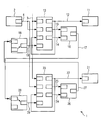
- the single FIGURE shows a block diagram with various function blocks, from which a control device 1 can be constructed.
- a control circuit not shown with a process, such as a bioreactor, serve a measuring element 2, for example, a sensor for detecting the oxygen partial pressure, and a first actuator 11, for example, a valve for adjusting the amount of air injection, and a second actuator 21, for example a stirrer with upstream speed control.
- the first actuator 11 is for generating a first manipulated variable 12, a first PID controller 13, the second actuator 21 for generating a second manipulated variable 22, a second PID controller 23 upstream.
- a set value 3 for the detected by means of the measuring element 2 control variable 4 is given, which is also supplied to both controllers 13 and 23.
- the two controllers 13 and 23 calculate a control difference which is needed internally for determining the first control variable 12 or the second control variable 22 according to the control algorithm respectively parameterized in the first controller 13 or in the second controller 23, if the respective one Controller operates in automatic mode.
- a manipulated variable limiting device In a manipulated variable limiting device, not shown in more detail, different limit values for the lower limits and the upper limits of their setting ranges are stored in the first controller 13 and in the second controller 23. If the first manipulated variable 12 of the first controller 13 reaches the lower limit value of the first manipulated variable 12, this is achieved by a high level of a Display signal 14 of a logic circuit with a first OR gate 16 is displayed. In a corresponding manner, the second controller 23 is connected to a second OR gate 26, to which display signals 24 and 25 for reaching a lower limit or an upper limit of the adjustment range of the second controller 23 are guided.
- the logical output signal 17 of the first OR element 16 is fed via a logical negation, which is symbolized by a circle, to a first input of a first selector 28.
- the negated logic signal 17 is switched through to the selector output and guided as an activation signal 29 to an input for activating the Nachrios worriess the second controller 23 at high level.
- a second logic output signal 27 is used at a position deviating from the illustrated state of a second selector 18 for generating an activation signal 19 for a tracking operation of the first controller 13.
- In the illustrated switching state of the selector 18 delivers this at its output an activation signal 19 with low level, so that the controller 13 operates as a primary controller in automatic mode.
- the first manipulated variable 12 is, in addition to its connection to the first actuator 11, guided to an input of the first controller 13 for a default value, which is output as the first manipulated variable 12 in the tracking mode.
- the first controller 13 is the primary controller which constantly operates in automatic mode.
- the second controller 23 is in follow-up mode, for example, and outputs a constant value for the second manipulated variable 22.
- the first controller 13 with its manipulated variable 12 abuts the upper or lower limit, this is done by High level on the display signal 15 and the display signal 14 is displayed and the first OR gate 16 switches via the second selector 28 a low level to the activation signal 29, so that the tracking operation of the second controller 23 is deactivated and thus to support of the first controller 13 switches to automatic mode. If the first controller 13 leaves the limitation of the setting range again, the second controller 23 goes back into tracking mode, specifically in such a way that the value of the second manipulated variable 22 output last is kept constant.
- the limit values for the respective setting range stored in the manipulated variable limiting devices of the first controller 13 and the second controller 23 may be static or alternatively variable, so that they are changed depending on the course of the process or, for example, determined by economic considerations.
- the manual mode has priority over the mode of tracking, so that in manual mode for each secondary controller a default for the constant value of the respective manipulated variable can be made.
- the respective controller Due to the reconnection of the first manipulated variable 12 or the second manipulated variable 22 to the tracking input of the first controller 13 and of the second controller 23, the respective controller remembers the value of the manipulated variable 12 or 22 last output and keeps it constant as long as the tracking mode is activated is.
- the two selectors 18 and 28 are always adjusted in opposite directions. If the second controller 23 is to be the primary controller, the selectors 18 and 28 are both set differently from the illustrated state, so that only the activation input for tracking operation of the first controller 13 is addressed, but not the corresponding activation input of the second controller 23.
- the symmetrically constructed Logic circuit consisting of the two OR gates 16, 26 and the two selectors 18, 28 makes it possible to modify during operation, the decision of which of the two controllers 13 or 23 should be the currently primary controller.
Description
Die Erfindung betrifft eine Regeleinrichtung für einen Prozess, in welchem eine Regelgröße mit Hilfe von mehreren verschiedenen Stellgliedern beeinflussbar ist, gemäß dem Oberbegriff des Anspruchs 1.The invention relates to a control device for a process in which a controlled variable can be influenced by means of a plurality of different actuators, according to the preamble of
In prozess- oder verfahrenstechnischen Anlagen tritt häufig der Fall auf, dass für die Beeinflussung einer Regelgröße zwei Stellglieder zur Verfügung stehen, die sich in ihrer Wirkung gegenseitig ergänzen. Jede Stellgröße, die auf eines der beiden Stellglieder geführt ist, hat für sich alleine, das heißt ohne Unterstützung durch die jeweils andere Stellgröße, nicht genügend Einfluss auf den Prozess, um die Regelgröße in allen Betriebszuständen auf dem Sollwert zu halten. Die beiden Stellgrößen können sich zudem im Hinblick auf die Geschwindigkeit, mit der sie auf den Prozess einwirken, sowie im Hinblick auf die Kosten und unerwünschten Nebenwirkungen, mit welchen ein Stelleingriff verbunden sein kann, unterscheiden. Im Normalfall sollen beide Stellgrößen gleichzeitig aktiv sein.In process or process plants, it often happens that two actuators are available for influencing a controlled variable, which complement each other in their effect. Each manipulated variable, which is guided on one of the two actuators, has by itself, ie without the support of the other manipulated variable, not enough influence on the process to keep the controlled variable in all operating states at the setpoint. The two manipulated variables can also differ in terms of the speed with which they act on the process, as well as with regard to the costs and undesired side effects with which a control intervention can be associated. Normally, both manipulated variables should be active at the same time.
Als Beispiel sei die Regelung des Sauerstoff-Partialdrucks in einem Bioreaktor genannt, der oft auch als Fermenter bezeichnet wird. Der Sauerstoff-Partialdruck als Regelgröße, welcher dem Sauerstoffgehalt der im Fermenter befindlichen Brühe entspricht, kann sowohl durch die Einblasung von Luft oder Sauerstoff mit Hilfe eines ersten Stellglieds als auch durch Veränderung der Rührerdrehzahl mittels eines zweiten Stellglieds beeinflusst werden. Dabei soll sich der Rührer immer drehen und es soll permanent Frischluft zugeführt werden. Zur Schonung der lebenden Zellen im Reaktor darf jedoch nicht zu stark gerührt und auch nicht zu viel Luft eingeblasen werden.An example is the regulation of the oxygen partial pressure in a bioreactor, which is often referred to as a fermenter. The oxygen partial pressure as a controlled variable, which corresponds to the oxygen content of the broth in the fermenter, can be influenced both by the injection of air or oxygen by means of a first actuator and by changing the stirrer speed by means of a second actuator. The stirrer should always turn and fresh air should be constantly supplied. To protect the living cells in the reactor, however, should not be stirred too much and not too much air to be blown.
Eine mögliche Vorgehensweise bei der Regelung eines derartigen Prozesses wäre eine teilweise Automatisierung, bei welcher ein konventioneller PID-Regler eine erste Stellgröße für eines der beiden Stellglieder erzeugt und eine zweite Stellgröße im Handbetrieb vorgegeben wird. Falls das Regelungsziel mit dem aktuellen Vorgabewert nicht mehr erreicht werden kann, wird durch eine Alarmmeldung ein Anlagenfahrer darüber informiert, der bei Bedarf in einem manuellen Eingriff die zweite Stellgröße verändern kann. Im Rahmen von Rezeptsteuerungen können derartige Eingriffe in bestimmten Phasen der Herstellung einer Charge automatisiert vorgenommen werden, falls ihre Notwendigkeit im Rezeptablauf vorhersehbar ist.One possible approach to controlling such a process would be partial automation in which a conventional PID controller generates a first manipulated variable for one of the two actuators and a second manipulated variable is specified in manual mode. If the control target can no longer be reached with the current default value, an alarm message informs a system operator who, if necessary, can change the second manipulated variable in a manual intervention. In the context of recipe controls, such interventions can be automated in certain stages of the production of a batch, if their necessity in the recipe sequence is foreseeable.
Aus dem Funktionshandbuch "SIMATIC Prozessleitsystem PCS 7, PCS 7 Advanced Process Library V71" 03/2009, A5E02102721-01, der Siemens AG ist eine so genannte "Split-Range-Regelung" als Lösung eines etwas anders gelagerten Problems bekannt. Mit Hilfe eines "Split-Range-Bausteins" hinter dem Reglerausgang kann ein PID-Regler seinen Stellwert auf mehrere verschiedene Stellglieder verteilen, die mit verschiedenen physikalischen Prinzipien und in verschiedener Richtung auf dieselbe Regelgröße einwirken. Ein typisches Beispiel ist die Temperaturregelung in einem Reaktor mit Heizung über ein Frischdampfventil und Kühlung über ein Kühlwasserventil. Abhängig vom Vorzeichen der Regeldifferenz kann der Regler Heizenergie oder Kühlenergie anfordern, das heißt, er kann mit einem bidirektionalen Ausgang arbeiten, obwohl jedes einzelne Stellglied nur unipolar, das heißt in einer Wirkrichtung, betrieben werden kann. Bei der bekannten Split-Range-Regelung ist somit entweder das eine oder das andere Stellglied aktiv, aber nicht beide zugleich, da beide in unterschiedlichen Richtungen wirken. In diesem Beispiel macht es nämlich keinen Sinn, gleichzeitig zu heizen und zu kühlen.From the "SIMATIC Process Control System PCS 7, PCS 7 Advanced Process Library V71" 03/2009, A5E02102721-01 functional manual, Siemens AG is familiar with so-called "split-range control" as the solution to a slightly different problem. With the aid of a "split-range module" behind the controller output, a PID controller can distribute its manipulated variable to several different actuators, which act on the same controlled variable with different physical principles and in different directions. A typical example is the temperature control in a reactor with heating via a live steam valve and cooling via a cooling water valve. Depending on the sign of the control difference, the controller can request heating energy or cooling energy, that is, he can work with a bidirectional output, although each individual actuator can only unipolar, that is, in a direction of action, can be operated. In the known split-range control is thus either the one or the other actuator active, but not both at the same time, since both act in different directions. In this example, it makes no sense to heat and cool at the same time.
Aus der
Der Erfindung liegt die Aufgabe zugrunde, eine Regeleinrichtung für einen Prozess, in welchem eine Regelgröße mit Hilfe von mehreren verschiedenen Stellgliedern beeinflussbar ist, zu schaffen, die es in einfacher Weise ermöglicht, zwei Stellglieder zu betreiben, welche dieselbe Wirkrichtung besitzen und gleichzeitig aktiv sein können.The invention has for its object to provide a control device for a process in which a controlled variable can be influenced by means of several different actuators, which allows in a simple manner to operate two actuators, which have the same direction of action and can be active simultaneously ,
Zur Lösung dieser Aufgabe weist die neue Regeleinrichtung der eingangs genannten Art die im kennzeichnenden Teil des Anspruchs 1 angegebenen Merkmale auf. In den abhängigen Ansprüchen sind vorteilhafte Weiterbildungen der Erfindung, im Anspruch 6 ein Regelungsverfahren, in den Ansprüchen 7 und 8 ein entsprechendes Computerprogramm bzw. ein Computerprogrammprodukt beschrieben.To solve this problem, the new control device of the type mentioned in the characterizing part of
Mit anderen Worten besteht die grundlegende Idee der neuen Regeleinrichtung darin, für beide Stellglieder einen separaten Regler, insbesondere einen separaten PID-Regler, vorzusehen, die beide mit derselben Regelgröße beaufschlagt werden und beide - wie auch die Stellglieder - denselben Wirkungssinn haben. Beide Regler sind permanent mit ihrem jeweiligen Stellglied verbunden. Durch Vorgabe geeigneter Stellgrößenbegrenzungen wird sichergestellt, dass beide Stellglieder nicht ganz abgeschaltet werden. Je nach Applikation, das heißt je nach Art des Prozesses und der verwendeten Stellglieder, wird entschieden, welche Stellgröße die primäre und somit welcher Regler der primäre Regler sein sollen. Solange der primäre Regler mit seinem Stellbereich, der durch die vorgegebenen Stellgrößenbegrenzungen festgelegt ist, in der Lage ist, einen beispielsweise durch einen Bediener vorgegebenen Sollwert zu erreichen, bleibt der zweite Regler, welcher auch als sekundärer Regler bezeichnet werden kann, im Nachführbetrieb mit konstanter Stellgröße. Sobald der primäre Regler an eine seiner Grenzen des Stellbereichs stößt, wird der sekundäre Regler zusätzlich aktiviert, das heißt er wird vom Nachführbetrieb in den Automatikbetrieb genommen.In other words, the basic idea of the new control device is to provide for both actuators a separate controller, in particular a separate PID controller, which are both acted upon by the same control variable and both - have the same sense of action - as well as the actuators. Both controllers are permanently connected to their respective actuator. By specifying suitable manipulated variable limits, it is ensured that both actuators are not completely switched off. Depending on the application, that is, depending on the type of process and the actuators used, it is decided which manipulated variable should be the primary and thus which controller should be the primary controller. As long as the primary controller with its setting range, which is defined by the prescribed manipulated variable limits, is able to achieve a desired value specified, for example, by an operator, the second controller, which can also be referred to as a secondary controller, remains in follow-up mode with a constant manipulated variable , As soon as the primary controller reaches one of its limits of the setting range, the secondary controller is additionally activated, ie it is taken from the tracking mode to the automatic mode.
Gegenüber der eingangs beschriebenen, nur teilweise automatisierten Regeleinrichtung oder im Vergleich zu Rezeptsteuerungen hat die neue Regeleinrichtung den Vorteil, dass sie in der Lage ist, bei Stellgliedern, welche dieselbe Wirkrichtung besitzen, vollautomatisch und autark zu arbeiten. Wenn die Regeleinrichtung mit den darin verwendeten Reglern einmal korrekt parametriert ist, erfordert sie während ihres Betriebs keine weitere Aufmerksamkeit mehr von einem Bediener und es müssen z. B. bei einer Mehrproduktanlage keine speziellen Vorkehrungen mehr getroffen werden. Durch die Verwendung mehrerer Regler, die auf eine gemeinsame Regelgröße wirken, können jeweils unterschiedliche Stellglieder gemeinsam eingesetzt werden, um ein bestimmtes Regelungsziel somit schneller als bisher zu erreichen. Da es sich um verschiedene Regler handeln kann, die jeweils individuell parametriert werden, kann jeder Regler bezüglich seiner Dynamik auf das Verhalten des jeweils zugeordneten Stellglieds angepasst werden. Da die beiden Stellglieder typischerweise mit unterschiedlichen physikalischen Wirkprinzipien arbeiten, die zudem unterschiedlich schnell auf den Prozess einwirken, sind typischerweise auch unterschiedliche Parametersätze für die Regler erforderlich. Eine Inbetriebnahme der Regler, bei welcher die jeweils optimalen Parameter für die Regler ermittelt werden, kann in besonders einfacher Weise durchgeführt werden, indem jeweils nur einer von den mehreren Reglern aktiviert wird, während die jeweils anderen in Handbetrieb geschaltet sind, so dass letztere einen konstant vorgegebenen Wert der Stellgröße ausgeben. Dadurch können bekannte Verfahren zur rechnergestützten Inbetriebnahme von Reglern, beispielsweise der so genannte PID-Tuner, der in das Engineering-System des bekannten Prozessleitsystems SIMATIC PCS 7 integriert ist, zum Einsatz gebracht werden.Compared to the initially described, only partially automated control device or compared to recipe controls, the new control device has the advantage that it is able to work fully automatically and self-sufficient for actuators, which have the same direction of action. Once the controller with the controllers used in it is parameterized correctly, it requires it during its operation no further attention from an operator and it must, for. B. in a multi-product plant no special precautions are taken. By using several controllers that act on a common control variable, each different actuators can be used together to achieve a specific control target thus faster than before. Since these can be different controllers, each parameterized individually, each controller can be adapted in terms of its dynamics to the behavior of the associated actuator. Since the two actuators typically work with different physical principles of action, which also act at different speeds on the process, typically also different parameter sets for the controller are required. A commissioning of the controller, in which the respectively optimum parameters for the controller are determined, can be carried out in a particularly simple manner by activating only one of the several controllers, while the other are switched to manual mode, so that the latter one constant output specified value of the manipulated variable. As a result, known methods for computer-aided commissioning of controllers, such as the so-called PID tuner, which is integrated into the engineering system of the known process control system SIMATIC PCS 7, are used.
Ein weiterer Vorteil ist darin zu sehen, dass für die Regler nur ein gemeinsamer Sollwert vorgegeben werden muss, der für alle Regler der gleiche ist, wodurch sich die Bedienung der Regler in der Anlage erheblich erleichtert.Another advantage is the fact that for the controller only a common setpoint must be specified, which is the same for all controllers, making the operation of the controller in the system much easier.
In einer vorteilhaften Weiterbildung der Erfindung sind die Grenzwerte für die Stellgrößenbegrenzung des jeweiligen primären Reglers in Abhängigkeit des jeweiligen Prozesszustands oder der Zeit veränderbar. Damit kann auf besondere Gegebenheiten beim Betrieb der Anlage reagiert werden, zum Beispiel, wenn der Betrieb der Stellglieder mit unterschiedlichem Ressourcenverbrauch verbunden ist und zum Beispiel Energiekosten zeitabhängig variabel sind.In an advantageous development of the invention, the limit values for the manipulated variable limitation of the respective primary regulator can be changed as a function of the respective process state or time. This can be responded to particular circumstances in the operation of the system, for example, when the operation of the actuators with different resource consumption is connected and, for example, energy costs are variable depending on time.
Durch eine Rückverschaltung des Stellgrößenausgangs auf den Vorgabewert für das Nachführen im Nachführbetrieb, bei welcher die Stellgröße des sekundären Reglers auf seinen Eingang für den Vorgabewert geführt ist, wird in vorteilhafter Weise erreicht, dass der sekundäre Regler bei der Umschaltung von Automatikbetrieb in den Nachführbetrieb den zuvor gültigen Stellwert übernimmt und danach konstant hält. Dies bewirkt ein stoßfreies Umschalten des sekundären Reglers.By a reconnection of the manipulated variable output to the default value for tracking in Nachführbetrieb, in which the manipulated variable of the secondary controller is guided to its input for the default value, is achieved in an advantageous manner that the secondary controller in the switching from automatic mode to the Nachführbetrieb the previously valid control value and then keeps constant. This causes a bumpless switching of the secondary regulator.
In einer weiteren vorteilhaften Ausgestaltung der Erfindung ist der sekundäre Regler derart ausgestaltet, dass ein Bediener diesen in Handbetrieb schalten kann, in welchem der Stellwert durch den Bediener vorgebbar ist. Durch eine Priorität von Handbetrieb gegenüber Nachführen wird ermöglicht, dass dem jeweils sekundären Regler ein gewünschter, konstanter Stellwert vorgegeben werden kann, der solange stehen bleibt, bis der sekundäre Regler von dieser Betriebsart in den Automatikbetrieb umgeschaltet wird. Vorteilhaft ist zudem eine Logikschaltung, mit welcher die Auswahl, welcher der Regler aktuell als primärer Regler arbeiten soll, flexibel vorgegeben und sogar während des Betriebs der Regeleinrichtung geändert werden kann.In a further advantageous embodiment of the invention, the secondary controller is configured such that an operator can switch it into manual operation, in which the control value can be predetermined by the operator. A priority of manual operation compared to tracking makes it possible that the respective secondary controller, a desired, constant control value can be specified, which remains until the secondary controller is switched from this mode to the automatic mode. Also advantageous is a logic circuit with which the selection of which controller is currently to operate as a primary controller can be flexibly specified and even changed during operation of the controller.
Ein Verfahren zur Regelung eines Prozesses, welches mit der Regeleinrichtung durchführbar ist, ist bevorzugt in Software oder einer Kombination von Soft-/Hardware implementiert, so dass die Erfindung auch ein Computerprogramm mit durch einen Computer ausführbaren Programmcodeanweisungen zur Implementierung des Verfahrens betrifft. In diesem Zusammenhang betrifft die Erfindung auch ein Computerprogrammprodukt, insbesondere einen Datenträger oder ein Speichermedium, mit einem durch einen Computer ausführbaren derartigen Computerprogramm. Ein solches Computerprogramm ist bevorzugt Bestandteil eines Automatisierungsgeräts, durch welches die Regeleinrichtung realisiert ist, oder wird in einem Speicher des Automatisierungsgeräts vorgehalten oder ist in diesen Speicher ladbar, so dass beim Betrieb des Automatisierungsgeräts dieses das Verfahren zur Regelung des Prozesses automatisch ausführt.A method for controlling a process that is feasible with the control device is preferably implemented in software or a combination of software / hardware, so that the invention also relates to a computer program with computer-executable program code instructions for implementing the method. In this context, the invention also relates to a computer program product, in particular a data carrier or a storage medium, with a computer program executable by a computer. Such a computer program is preferably part of an automation device, by which the control device is realized, or is in a memory of the programmable controller held or is in this memory loadable, so that automatically performs the process for controlling the process during operation of the automation device.
Anhand der Zeichnung, in welcher ein Ausführungsbeispiel der Erfindung dargestellt ist, werden im Folgenden die Erfindung sowie Ausgestaltungen und Vorteile näher erläutert.Reference to the drawing, in which an embodiment of the invention is shown, the invention and refinements and advantages are explained in more detail below.
Die einzige Figur zeigt ein Blockschaltbild mit verschiedenen Funktionsblöcken, aus welchen eine Regeleinrichtung 1 aufgebaut sein kann. Zur Einbindung der Regeleinrichtung 1 in einen nicht weiter dargestellten Regelkreis mit einem Prozess, beispielsweise einem Bioreaktor, dienen ein Messglied 2, zum Beispiel ein Sensor zur Erfassung des Sauerstoff-Partialdrucks, sowie ein erstes Stellglied 11, zum Beispiel ein Ventil zur Mengeneinstellung einer Lufteinblasung, und ein zweites Stellglied 21, zum Beispiel ein Rührwerk mit vorgeschalteter Drehzahlregelung. Dem ersten Stellglied 11 ist zur Erzeugung einer ersten Stellgröße 12 ein erster PID-Regler 13, dem zweiten Stellglied 21 zur Erzeugung einer zweiten Stellgröße 22 ein zweiter PID-Regler 23 vorgeschaltet. Durch Bedieneingabe wird den beiden Reglern 13 und 23 ein Sollwert 3 für die mit Hilfe des Messglieds 2 erfasste Regelgröße 4 vorgegeben, die ebenfalls beiden Reglern 13 und 23 zugeführt ist. Anhand Sollwert 3 und Regelgröße 4 berechnen die beiden Regler 13 und 23 eine Regeldifferenz, welche intern zur Bestimmung der ersten Stellgröße 12 bzw. der zweiten Stellgröße 22 entsprechend dem jeweils im ersten Regler 13 oder im zweiten Regler 23 parametrierten Regelalgorithmus benötigt wird, falls der jeweilige Regler im Automatikbetrieb arbeitet.The single FIGURE shows a block diagram with various function blocks, from which a
In einer nicht näher dargestellten Stellgrößenbegrenzungseinrichtung sind im ersten Regler 13 sowie im zweiten Regler 23 verschiedene Grenzwerte für die Untergrenzen und die Obergrenzen ihrer Stellbereiche hinterlegt. Erreicht die erste Stellgröße 12 des ersten Reglers 13 den unteren Grenzwert der ersten Stellgröße 12, so wird dies durch einen High-Pegel eines Anzeigesignals 14 einer Logikschaltung mit einem ersten Oder-Glied 16 angezeigt. Zur Anzeige des Erreichens eines oberen Grenzwerts dient ein Anzeigesignal 15. In entsprechender Weise ist auch der zweite Regler 23 mit einem zweiten Oder-Glied 26 verschaltet, auf welches Anzeigesignale 24 und 25 für das Erreichen eines unteren Grenzwerts bzw. eines oberen Grenzwerts des Stellbereichs des zweiten Reglers 23 geführt sind. Das logische Ausgangssignal 17 des ersten Oder-Glieds 16 ist über eine logische Negation, die durch einen Kreis symbolisiert ist, auf einen ersten Eingang eines ersten Selektors 28 geführt. Im dargestellten Schaltungszustand des Selektors 28 wird das negierte logische Signal 17 auf den Selektorausgang durchgeschaltet und als Aktivierungssignal 29 auf einen Eingang zur Aktivierung des Nachführbetriebs des zweiten Reglers 23 bei High-Pegel geführt. In entsprechender Weise wird ein zweites logisches Ausgangssignal 27 bei einer vom dargestellten Zustand abweichenden Stellung eines zweiten Selektors 18 zur Erzeugung eines Aktivierungssignals 19 für einen Nachführbetrieb des ersten Reglers 13 herangezogen. Im dargestellten Schaltzustand des Selektors 18 liefert dieser an seinem Ausgang ein Aktivierungssignal 19 mit Low-Pegel, so dass der Regler 13 als primärer Regler im Automatikbetrieb arbeitet.In a manipulated variable limiting device, not shown in more detail, different limit values for the lower limits and the upper limits of their setting ranges are stored in the
Die erste Stellgröße 12 ist zusätzlich zu ihrer Aufschaltung auf das erste Stellglied 11 auf einen Eingang des ersten Reglers 13 für einen Vorgabewert geführt, welcher im Nachführbetrieb als erste Stellgröße 12 ausgegeben wird. Entsprechendes gilt für die durch den zweiten Regler 23 erzeugte zweite Stellgröße 22.The first manipulated
In der jeweils durch einen Pfeil in den Selektoren 18 und 28 symbolisierten Selektorstellung ist der erste Regler 13 der primäre Regler, der ständig im Automatikbetrieb arbeitet. Der zweite Regler 23 befindet sich beispielsweise im Nachführbetrieb und gibt einen konstanten Wert für die zweite Stellgröße 22 aus. Wenn der erste Regler 13 mit seiner Stellgröße 12 an die obere oder untere Begrenzung stößt, wird dies durch High-Pegel auf dem Anzeigesignal 15 bzw. dem Anzeigesignal 14 angezeigt und das erste Oder-Glied 16 schaltet über den zweiten Selektor 28 einen Low-Pegel auf das Aktivierungssignal 29, so dass der Nachführbetrieb des zweiten Reglers 23 deaktiviert wird und er somit zur Unterstützung des ersten Reglers 13 in Automatikbetrieb schaltet. Falls der erste Regler 13 die Begrenzung des Stellbereichs wieder verlässt, geht der zweite Regler 23 zurück in Nachführbetrieb und zwar so, dass der zuletzt ausgegebene Wert der zweiten Stellgröße 22 konstant gehalten wird.In the selector position symbolized in each case by an arrow in the
Die in den Stellgrößenbegrenzungseinrichtungen des ersten Reglers 13 und des zweiten Reglers 23 hinterlegten Grenzwerte für den jeweiligen Stellbereich können statisch oder alternativ dazu variabel sein, sodass sie abhängig vom Verlauf des Prozesses oder beispielsweise bestimmt durch ökonomische Gesichtspunkte verändert werden.The limit values for the respective setting range stored in the manipulated variable limiting devices of the
Am ersten Regler 13 sowie am zweiten Regler 23 hat die Betriebsart Handbetrieb Priorität vor der Betriebsart Nachführen, so dass im Handbetrieb für den jeweils sekundären Regler eine Vorgabe für den konstanten Wert der jeweiligen Stellgröße gemacht werden kann.On the
Durch die Rückverschaltung der ersten Stellgröße 12 bzw. der zweiten Stellgröße 22 auf den Nachführeingang des ersten Reglers 13 bzw. des zweiten Reglers 23 merkt sich der jeweilige Regler den zuletzt ausgegebenen Wert der Stellgröße 12 bzw. 22 und hält ihn konstant, solange der Nachführbetrieb aktiviert ist.Due to the reconnection of the first manipulated variable 12 or the second manipulated variable 22 to the tracking input of the
Die beiden Selektoren 18 und 28 werden immer gegenläufig verstellt. Falls der zweite Regler 23 der primäre Regler werden soll, werden die Selektoren 18 und 28 beide abweichend vom dargestellten Zustand eingestellt, so dass nur der Aktivierungseingang für Nachführbetrieb des ersten Reglers 13 angesprochen wird, nicht dagegen der entsprechende Aktivierungseingang des zweiten Reglers 23. Durch die symmetrisch aufgebaute Logikschaltung, bestehend aus den beiden Oder-Gliedern 16, 26 und den beiden Selektoren 18, 28 wird es ermöglicht, im laufenden Betrieb die Entscheidung zu modifizieren, welcher der beiden Regler 13 oder 23 der aktuell primäre Regler sein soll.The two
Claims (8)
- Control device (1) for a process, in which a controlled variable (4) can be influenced with the aid of a plurality of different control elements (11, 21) which are based particularly on different physical principles, characterized in that
a first controller (13) is arranged upstream from a first control element (11) for generating a first manipulated variable (12) and a second controller (23) is arranged upstream from a second control element (21), which has the same operating direction as the first control element (11), for generating a second manipulated variable (22),
the set point (3) and the controlled variable (4) are fed to the first controller and the second controller (13, 23),
the first controller (13) is in automatic mode as the primary controller and is provided with a manipulated variable limitation device having specified or specifiable limit values for the first manipulated variable (12),
the second controller (23) can be switched between automatic mode and a tracking mode, in which it generates a specified or specifiable constant value of the second manipulated variable (22), and
a logic circuit (16, 26, 18, 28) exists that is configured to switch the second controller (23) into automatic mode if a limit value of the first manipulated variable (12) is reached, and otherwise to switch the second controller (23) into tracking mode. - Control device according to Claim 1, characterized in that the limit values for the first manipulated variable (12) can be changed as a function of the respective process state or as a function of time.
- Control device according to Claim 1 or 2, characterized in that the second manipulated variable (22) is routed in tracking mode to an input of the second controller (23) for a specified value of the manipulated variable.
- Control device according to one of the previous claims, characterized in that the second controller (23) can be switched manually by an operator in manual mode.
- Control device according to one of the previous claims, characterized in that the second controller (23) is provided with a manipulated variable limitation device having specified or specifiable limit values for the second manipulated variable (22),
the first controller (13) can be switched between automatic mode and a tracking mode, in which it generates a specified or specifiable constant value of the first manipulated variable (12), and
the logic circuit (16, 26, 18, 28) is furthermore configured to switch the second controller (23) into automatic mode, so that it is operated as the primary controller, and to switch the first controller, which then is no longer operated as the primary controller, into automatic mode, if a limit value of the second manipulated variable (22) is reached, and otherwise to switch the first controller (13) into tracking mode. - Method for controlling a process, in which a controlled variable (4) can be influenced with the aid of a plurality of different control elements (11, 21), which are based particularly on different physical principles, having a control device in which a first controller (13) is arranged upstream from a first control element (11) for generating a first manipulated variable (12) and a second controller (23) is arranged upstream from a second control element (21), which has the same operating direction as the first control element (11), for generating a second manipulated variable (22), characterized in that
the set point (3) and the controlled variable (4) are fed to the first controller and the second controller (13, 23), the first controller (13) works as the primary controller in an automatic mode and is provided with a manipulated variable limitation device having specified or specifiable limit values for the first manipulated variable (12),
the second controller (23) can be switched between automatic mode and a tracking mode, in which it generates a specified or specifiable constant value for the second manipulated variable (22), and
a logic circuit (16, 26, 18, 28) switches the second controller (23) into automatic mode if a limit value of the first manipulated variable (12) is reached, and otherwise switches the second controller (23) into tracking mode. - Computer program having program code instructions that are executable by a computer for implementing the method according to Claim 6, if the computer program is executed on a computer.
- Computer program product, in particular, a data carrier or a storage medium, having a computer program that is executable by a computer according to Claim 7.
Applications Claiming Priority (1)
| Application Number | Priority Date | Filing Date | Title |
|---|---|---|---|
| PCT/EP2010/067597 WO2012065631A1 (en) | 2010-11-16 | 2010-11-16 | Control device |
Publications (2)
| Publication Number | Publication Date |
|---|---|
| EP2641133A1 EP2641133A1 (en) | 2013-09-25 |
| EP2641133B1 true EP2641133B1 (en) | 2014-09-10 |
Family
ID=43929098
Family Applications (1)
| Application Number | Title | Priority Date | Filing Date |
|---|---|---|---|
| EP10779543.7A Active EP2641133B1 (en) | 2010-11-16 | 2010-11-16 | Control device |
Country Status (4)
| Country | Link |
|---|---|
| US (1) | US9823629B2 (en) |
| EP (1) | EP2641133B1 (en) |
| CN (1) | CN103210356B (en) |
| WO (1) | WO2012065631A1 (en) |
Families Citing this family (2)
| Publication number | Priority date | Publication date | Assignee | Title |
|---|---|---|---|---|
| EP2874030A1 (en) * | 2013-11-19 | 2015-05-20 | Siemens Aktiengesellschaft | Automation system |
| US11101638B2 (en) | 2018-10-05 | 2021-08-24 | Analog Devices Global Unlimited Company | Semiconductor die including multiple controllers for operating over an extended temperature range |
Family Cites Families (13)
| Publication number | Priority date | Publication date | Assignee | Title |
|---|---|---|---|---|
| DE2046990A1 (en) * | 1970-09-24 | 1972-03-30 | Bosch Elektronik Gmbh | Control device for keeping an electrical variable constant |
| US4059745A (en) * | 1976-09-29 | 1977-11-22 | Fischer & Porter Co. | Override process control system |
| US4281970A (en) * | 1979-06-15 | 1981-08-04 | Phillips Petroleum Company | Turbo-expander control |
| EP0057541A1 (en) * | 1981-01-23 | 1982-08-11 | Babcock-Bristol Limited | Improvements in or relating to single loop control system |
| US4769056A (en) * | 1987-03-16 | 1988-09-06 | Phillips Petroleum Company | Distillation pressure control |
| US6445231B1 (en) * | 2000-06-01 | 2002-09-03 | Micron Technology, Inc. | Digital dual-loop DLL design using coarse and fine loops |
| DE10205375A1 (en) * | 2002-02-09 | 2003-08-21 | Bosch Gmbh Robert | Method and device for controlling an internal combustion engine, in particular for regulating the speed of the internal combustion engine |
| US6783080B2 (en) * | 2002-05-16 | 2004-08-31 | Advanced Thermal Sciences Corp. | Systems and methods for controlling temperatures of process tools |
| US7801521B2 (en) | 2005-05-18 | 2010-09-21 | Telefonaktiebolaget L M Ericsson (Publ) | System and method for communicating with aircraft through cellular base station towers |
| CN100523770C (en) | 2006-01-12 | 2009-08-05 | 中国兵器装备集团摩托车检测技术研究所 | Automatic simulating unmanned motorcycle driving system |
| US8196310B2 (en) * | 2007-02-09 | 2012-06-12 | Usnr/Kockums Cancar Company | Method and apparatus for controlling cooling temperature and pressure in wood veneer jet dryers |
| CN100535513C (en) * | 2007-04-29 | 2009-09-02 | 上海红箭自动化设备有限公司 | Control method of boiler water level and its control system |
| CN201546938U (en) * | 2009-09-14 | 2010-08-11 | 福建中试所电力调整试验有限责任公司 | Automatic shock absorption control device of frequency conversion pump |
-
2010
- 2010-11-16 WO PCT/EP2010/067597 patent/WO2012065631A1/en active Application Filing
- 2010-11-16 CN CN201080070060.0A patent/CN103210356B/en active Active
- 2010-11-16 US US13/883,744 patent/US9823629B2/en active Active
- 2010-11-16 EP EP10779543.7A patent/EP2641133B1/en active Active
Also Published As
| Publication number | Publication date |
|---|---|
| EP2641133A1 (en) | 2013-09-25 |
| US20140094937A1 (en) | 2014-04-03 |
| US9823629B2 (en) | 2017-11-21 |
| CN103210356B (en) | 2015-11-25 |
| CN103210356A (en) | 2013-07-17 |
| WO2012065631A1 (en) | 2012-05-24 |
Similar Documents
| Publication | Publication Date | Title |
|---|---|---|
| EP2980662B1 (en) | Protection for an automation component against program manipulation by means of signature matching | |
| EP2376783B2 (en) | Simulation-supported method for controlling and regulating compressed air stations | |
| EP3347169B1 (en) | Method and system for controlling a robot arrangement | |
| EP2579112B1 (en) | Regulating device | |
| EP2941675B1 (en) | Method for the computerized control and/or regulation of a technical system | |
| EP0706680B1 (en) | Control device, especially for a non-linear process varying in time | |
| EP2913502A1 (en) | Method for operating a combustion engine coupled with a generator and device for carrying out the method | |
| WO2022017711A1 (en) | Position controller self-assessment for digital twin | |
| EP2641133B1 (en) | Control device | |
| EP2288969B1 (en) | Control system of a plant having multi-stage model optimization | |
| WO2017055197A1 (en) | Neutralization system | |
| EP1478986B1 (en) | Method and device for controlling the speed of an internal combustion engine | |
| WO2008074736A1 (en) | Drive device for at least one electric motor and drive control unit interacting with the drive device | |
| EP0590430A2 (en) | Device for the automatic control of a processing plant by means of fuzzy logic control having preferred applications | |
| EP4045982A1 (en) | Monitoring method for monitoring at least one part of a production process of a film extrusion system | |
| EP2732343B1 (en) | Automated adaptation of a power plant control | |
| EP3825788B1 (en) | Control device, control system and control method for regulating a physical quantity of a fluid | |
| EP3045675B1 (en) | System and method for controlling a turbine inlet valve | |
| EP0819272B1 (en) | Programming device | |
| DE10106312A1 (en) | Methane gas generator regulation involves variation of operating parameter in relation to optimization target parameter | |
| DE2943354A1 (en) | Start=up control for process regulator - has facility for correction of command if preset limits are exceeded | |
| EP2506097B1 (en) | Regulation system for controlling an actuator, method for operating an actuator and computer program product | |
| DE19601232A1 (en) | Control circuit regulating unit | |
| WO2003107102A1 (en) | Control system and control method, particularly for a non-linear time-variant process | |
| EP3095015B1 (en) | Apparatus and method for operating an automation plant with reduced energy consumption |
Legal Events
| Date | Code | Title | Description |
|---|---|---|---|
| PUAI | Public reference made under article 153(3) epc to a published international application that has entered the european phase |
Free format text: ORIGINAL CODE: 0009012 |
|
| 17P | Request for examination filed |
Effective date: 20130423 |
|
| AK | Designated contracting states |
Kind code of ref document: A1 Designated state(s): AL AT BE BG CH CY CZ DE DK EE ES FI FR GB GR HR HU IE IS IT LI LT LU LV MC MK MT NL NO PL PT RO RS SE SI SK SM TR |
|
| RIN1 | Information on inventor provided before grant (corrected) |
Inventor name: LUEBBERT, ANDREAS Inventor name: KUPRIJANOV, ARTUR Inventor name: SIMUTIS, RIMVYDAS Inventor name: PFEIFFER, BERND-MARKUS Inventor name: SCHAEPE, SEBASTIAN |
|
| DAX | Request for extension of the european patent (deleted) | ||
| GRAP | Despatch of communication of intention to grant a patent |
Free format text: ORIGINAL CODE: EPIDOSNIGR1 |
|
| INTG | Intention to grant announced |
Effective date: 20140321 |
|
| GRAS | Grant fee paid |
Free format text: ORIGINAL CODE: EPIDOSNIGR3 |
|
| GRAA | (expected) grant |
Free format text: ORIGINAL CODE: 0009210 |
|
| AK | Designated contracting states |
Kind code of ref document: B1 Designated state(s): AL AT BE BG CH CY CZ DE DK EE ES FI FR GB GR HR HU IE IS IT LI LT LU LV MC MK MT NL NO PL PT RO RS SE SI SK SM TR |
|
| REG | Reference to a national code |
Ref country code: GB Ref legal event code: FG4D Free format text: NOT ENGLISH |
|
| REG | Reference to a national code |
Ref country code: CH Ref legal event code: EP |
|
| REG | Reference to a national code |
Ref country code: IE Ref legal event code: FG4D Free format text: LANGUAGE OF EP DOCUMENT: GERMAN |
|
| REG | Reference to a national code |
Ref country code: AT Ref legal event code: REF Ref document number: 686994 Country of ref document: AT Kind code of ref document: T Effective date: 20141015 |
|
| REG | Reference to a national code |
Ref country code: DE Ref legal event code: R096 Ref document number: 502010007880 Country of ref document: DE Effective date: 20141023 |
|
| PG25 | Lapsed in a contracting state [announced via postgrant information from national office to epo] |
Ref country code: FI Free format text: LAPSE BECAUSE OF FAILURE TO SUBMIT A TRANSLATION OF THE DESCRIPTION OR TO PAY THE FEE WITHIN THE PRESCRIBED TIME-LIMIT Effective date: 20140910 Ref country code: LT Free format text: LAPSE BECAUSE OF FAILURE TO SUBMIT A TRANSLATION OF THE DESCRIPTION OR TO PAY THE FEE WITHIN THE PRESCRIBED TIME-LIMIT Effective date: 20140910 Ref country code: NO Free format text: LAPSE BECAUSE OF FAILURE TO SUBMIT A TRANSLATION OF THE DESCRIPTION OR TO PAY THE FEE WITHIN THE PRESCRIBED TIME-LIMIT Effective date: 20141210 Ref country code: ES Free format text: LAPSE BECAUSE OF FAILURE TO SUBMIT A TRANSLATION OF THE DESCRIPTION OR TO PAY THE FEE WITHIN THE PRESCRIBED TIME-LIMIT Effective date: 20140910 Ref country code: GR Free format text: LAPSE BECAUSE OF FAILURE TO SUBMIT A TRANSLATION OF THE DESCRIPTION OR TO PAY THE FEE WITHIN THE PRESCRIBED TIME-LIMIT Effective date: 20141211 Ref country code: SE Free format text: LAPSE BECAUSE OF FAILURE TO SUBMIT A TRANSLATION OF THE DESCRIPTION OR TO PAY THE FEE WITHIN THE PRESCRIBED TIME-LIMIT Effective date: 20140910 |
|
| REG | Reference to a national code |
Ref country code: NL Ref legal event code: VDEP Effective date: 20140910 |
|
| REG | Reference to a national code |
Ref country code: LT Ref legal event code: MG4D |
|
| PG25 | Lapsed in a contracting state [announced via postgrant information from national office to epo] |
Ref country code: RS Free format text: LAPSE BECAUSE OF FAILURE TO SUBMIT A TRANSLATION OF THE DESCRIPTION OR TO PAY THE FEE WITHIN THE PRESCRIBED TIME-LIMIT Effective date: 20140910 Ref country code: HR Free format text: LAPSE BECAUSE OF FAILURE TO SUBMIT A TRANSLATION OF THE DESCRIPTION OR TO PAY THE FEE WITHIN THE PRESCRIBED TIME-LIMIT Effective date: 20140910 Ref country code: CY Free format text: LAPSE BECAUSE OF FAILURE TO SUBMIT A TRANSLATION OF THE DESCRIPTION OR TO PAY THE FEE WITHIN THE PRESCRIBED TIME-LIMIT Effective date: 20140910 Ref country code: LV Free format text: LAPSE BECAUSE OF FAILURE TO SUBMIT A TRANSLATION OF THE DESCRIPTION OR TO PAY THE FEE WITHIN THE PRESCRIBED TIME-LIMIT Effective date: 20140910 |
|
| PG25 | Lapsed in a contracting state [announced via postgrant information from national office to epo] |
Ref country code: NL Free format text: LAPSE BECAUSE OF FAILURE TO SUBMIT A TRANSLATION OF THE DESCRIPTION OR TO PAY THE FEE WITHIN THE PRESCRIBED TIME-LIMIT Effective date: 20140910 |
|
| PG25 | Lapsed in a contracting state [announced via postgrant information from national office to epo] |
Ref country code: CZ Free format text: LAPSE BECAUSE OF FAILURE TO SUBMIT A TRANSLATION OF THE DESCRIPTION OR TO PAY THE FEE WITHIN THE PRESCRIBED TIME-LIMIT Effective date: 20140910 Ref country code: EE Free format text: LAPSE BECAUSE OF FAILURE TO SUBMIT A TRANSLATION OF THE DESCRIPTION OR TO PAY THE FEE WITHIN THE PRESCRIBED TIME-LIMIT Effective date: 20140910 Ref country code: RO Free format text: LAPSE BECAUSE OF FAILURE TO SUBMIT A TRANSLATION OF THE DESCRIPTION OR TO PAY THE FEE WITHIN THE PRESCRIBED TIME-LIMIT Effective date: 20140910 Ref country code: SK Free format text: LAPSE BECAUSE OF FAILURE TO SUBMIT A TRANSLATION OF THE DESCRIPTION OR TO PAY THE FEE WITHIN THE PRESCRIBED TIME-LIMIT Effective date: 20140910 Ref country code: IS Free format text: LAPSE BECAUSE OF FAILURE TO SUBMIT A TRANSLATION OF THE DESCRIPTION OR TO PAY THE FEE WITHIN THE PRESCRIBED TIME-LIMIT Effective date: 20150110 Ref country code: PT Free format text: LAPSE BECAUSE OF FAILURE TO SUBMIT A TRANSLATION OF THE DESCRIPTION OR TO PAY THE FEE WITHIN THE PRESCRIBED TIME-LIMIT Effective date: 20150112 |
|
| PG25 | Lapsed in a contracting state [announced via postgrant information from national office to epo] |
Ref country code: PL Free format text: LAPSE BECAUSE OF FAILURE TO SUBMIT A TRANSLATION OF THE DESCRIPTION OR TO PAY THE FEE WITHIN THE PRESCRIBED TIME-LIMIT Effective date: 20140910 |
|
| REG | Reference to a national code |
Ref country code: DE Ref legal event code: R097 Ref document number: 502010007880 Country of ref document: DE |
|
| PG25 | Lapsed in a contracting state [announced via postgrant information from national office to epo] |
Ref country code: MC Free format text: LAPSE BECAUSE OF FAILURE TO SUBMIT A TRANSLATION OF THE DESCRIPTION OR TO PAY THE FEE WITHIN THE PRESCRIBED TIME-LIMIT Effective date: 20140910 Ref country code: BE Free format text: LAPSE BECAUSE OF NON-PAYMENT OF DUE FEES Effective date: 20141130 Ref country code: LU Free format text: LAPSE BECAUSE OF FAILURE TO SUBMIT A TRANSLATION OF THE DESCRIPTION OR TO PAY THE FEE WITHIN THE PRESCRIBED TIME-LIMIT Effective date: 20141116 |
|
| REG | Reference to a national code |
Ref country code: CH Ref legal event code: PL |
|
| PLBE | No opposition filed within time limit |
Free format text: ORIGINAL CODE: 0009261 |
|
| STAA | Information on the status of an ep patent application or granted ep patent |
Free format text: STATUS: NO OPPOSITION FILED WITHIN TIME LIMIT |
|
| PG25 | Lapsed in a contracting state [announced via postgrant information from national office to epo] |
Ref country code: DK Free format text: LAPSE BECAUSE OF FAILURE TO SUBMIT A TRANSLATION OF THE DESCRIPTION OR TO PAY THE FEE WITHIN THE PRESCRIBED TIME-LIMIT Effective date: 20140910 Ref country code: CH Free format text: LAPSE BECAUSE OF NON-PAYMENT OF DUE FEES Effective date: 20141130 Ref country code: LI Free format text: LAPSE BECAUSE OF NON-PAYMENT OF DUE FEES Effective date: 20141130 |
|
| 26N | No opposition filed |
Effective date: 20150611 |
|
| REG | Reference to a national code |
Ref country code: IE Ref legal event code: MM4A |
|
| PG25 | Lapsed in a contracting state [announced via postgrant information from national office to epo] |
Ref country code: IE Free format text: LAPSE BECAUSE OF NON-PAYMENT OF DUE FEES Effective date: 20141116 |
|
| REG | Reference to a national code |
Ref country code: FR Ref legal event code: PLFP Year of fee payment: 6 |
|
| PG25 | Lapsed in a contracting state [announced via postgrant information from national office to epo] |
Ref country code: SI Free format text: LAPSE BECAUSE OF FAILURE TO SUBMIT A TRANSLATION OF THE DESCRIPTION OR TO PAY THE FEE WITHIN THE PRESCRIBED TIME-LIMIT Effective date: 20140910 |
|
| PG25 | Lapsed in a contracting state [announced via postgrant information from national office to epo] |
Ref country code: SM Free format text: LAPSE BECAUSE OF FAILURE TO SUBMIT A TRANSLATION OF THE DESCRIPTION OR TO PAY THE FEE WITHIN THE PRESCRIBED TIME-LIMIT Effective date: 20140910 |
|
| PG25 | Lapsed in a contracting state [announced via postgrant information from national office to epo] |
Ref country code: BG Free format text: LAPSE BECAUSE OF FAILURE TO SUBMIT A TRANSLATION OF THE DESCRIPTION OR TO PAY THE FEE WITHIN THE PRESCRIBED TIME-LIMIT Effective date: 20140910 |
|
| PG25 | Lapsed in a contracting state [announced via postgrant information from national office to epo] |
Ref country code: TR Free format text: LAPSE BECAUSE OF FAILURE TO SUBMIT A TRANSLATION OF THE DESCRIPTION OR TO PAY THE FEE WITHIN THE PRESCRIBED TIME-LIMIT Effective date: 20140910 Ref country code: HU Free format text: LAPSE BECAUSE OF FAILURE TO SUBMIT A TRANSLATION OF THE DESCRIPTION OR TO PAY THE FEE WITHIN THE PRESCRIBED TIME-LIMIT; INVALID AB INITIO Effective date: 20101116 Ref country code: MT Free format text: LAPSE BECAUSE OF FAILURE TO SUBMIT A TRANSLATION OF THE DESCRIPTION OR TO PAY THE FEE WITHIN THE PRESCRIBED TIME-LIMIT Effective date: 20140910 |
|
| REG | Reference to a national code |
Ref country code: FR Ref legal event code: PLFP Year of fee payment: 7 |
|
| REG | Reference to a national code |
Ref country code: AT Ref legal event code: MM01 Ref document number: 686994 Country of ref document: AT Kind code of ref document: T Effective date: 20151116 |
|
| PG25 | Lapsed in a contracting state [announced via postgrant information from national office to epo] |
Ref country code: AT Free format text: LAPSE BECAUSE OF NON-PAYMENT OF DUE FEES Effective date: 20151116 |
|
| REG | Reference to a national code |
Ref country code: FR Ref legal event code: PLFP Year of fee payment: 8 |
|
| PG25 | Lapsed in a contracting state [announced via postgrant information from national office to epo] |
Ref country code: MK Free format text: LAPSE BECAUSE OF FAILURE TO SUBMIT A TRANSLATION OF THE DESCRIPTION OR TO PAY THE FEE WITHIN THE PRESCRIBED TIME-LIMIT Effective date: 20140910 |
|
| PG25 | Lapsed in a contracting state [announced via postgrant information from national office to epo] |
Ref country code: AL Free format text: LAPSE BECAUSE OF FAILURE TO SUBMIT A TRANSLATION OF THE DESCRIPTION OR TO PAY THE FEE WITHIN THE PRESCRIBED TIME-LIMIT Effective date: 20140910 |
|
| PGFP | Annual fee paid to national office [announced via postgrant information from national office to epo] |
Ref country code: DE Payment date: 20220620 Year of fee payment: 13 |
|
| PGFP | Annual fee paid to national office [announced via postgrant information from national office to epo] |
Ref country code: GB Payment date: 20231204 Year of fee payment: 14 |
|
| PGFP | Annual fee paid to national office [announced via postgrant information from national office to epo] |
Ref country code: IT Payment date: 20231122 Year of fee payment: 14 Ref country code: FR Payment date: 20231114 Year of fee payment: 14 |