EP1478986B1 - Method and device for controlling the speed of an internal combustion engine - Google Patents
Method and device for controlling the speed of an internal combustion engine Download PDFInfo
- Publication number
- EP1478986B1 EP1478986B1 EP02787391A EP02787391A EP1478986B1 EP 1478986 B1 EP1478986 B1 EP 1478986B1 EP 02787391 A EP02787391 A EP 02787391A EP 02787391 A EP02787391 A EP 02787391A EP 1478986 B1 EP1478986 B1 EP 1478986B1
- Authority
- EP
- European Patent Office
- Prior art keywords
- manipulated variable
- controller
- speed
- variable
- control
- Prior art date
- Legal status (The legal status is an assumption and is not a legal conclusion. Google has not performed a legal analysis and makes no representation as to the accuracy of the status listed.)
- Expired - Lifetime
Links
- 238000002485 combustion reaction Methods 0.000 title claims abstract description 21
- 238000000034 method Methods 0.000 title claims abstract description 20
- 230000008859 change Effects 0.000 claims description 12
- 238000004590 computer program Methods 0.000 claims description 6
- 230000007423 decrease Effects 0.000 claims description 5
- 230000001276 controlling effect Effects 0.000 description 10
- 230000006399 behavior Effects 0.000 description 5
- 239000000446 fuel Substances 0.000 description 4
- 230000006870 function Effects 0.000 description 3
- 230000008901 benefit Effects 0.000 description 2
- 230000033228 biological regulation Effects 0.000 description 2
- 230000005540 biological transmission Effects 0.000 description 2
- 238000004364 calculation method Methods 0.000 description 2
- 230000003247 decreasing effect Effects 0.000 description 2
- 238000001514 detection method Methods 0.000 description 2
- 238000010586 diagram Methods 0.000 description 2
- 230000001105 regulatory effect Effects 0.000 description 2
- 230000009471 action Effects 0.000 description 1
- 238000013459 approach Methods 0.000 description 1
- 238000012937 correction Methods 0.000 description 1
- 238000013461 design Methods 0.000 description 1
- 238000011161 development Methods 0.000 description 1
- 230000000694 effects Effects 0.000 description 1
- 238000010304 firing Methods 0.000 description 1
- 230000006872 improvement Effects 0.000 description 1
- 238000002347 injection Methods 0.000 description 1
- 239000007924 injection Substances 0.000 description 1
- 230000003993 interaction Effects 0.000 description 1
- 230000007935 neutral effect Effects 0.000 description 1
- 230000008092 positive effect Effects 0.000 description 1
- 238000004886 process control Methods 0.000 description 1
- 230000009467 reduction Effects 0.000 description 1
- 230000004044 response Effects 0.000 description 1
- 230000001052 transient effect Effects 0.000 description 1
- 230000007704 transition Effects 0.000 description 1
Images


Classifications
-
- G—PHYSICS
- G05—CONTROLLING; REGULATING
- G05B—CONTROL OR REGULATING SYSTEMS IN GENERAL; FUNCTIONAL ELEMENTS OF SUCH SYSTEMS; MONITORING OR TESTING ARRANGEMENTS FOR SUCH SYSTEMS OR ELEMENTS
- G05B11/00—Automatic controllers
- G05B11/01—Automatic controllers electric
- G05B11/36—Automatic controllers electric with provision for obtaining particular characteristics, e.g. proportional, integral, differential
-
- F—MECHANICAL ENGINEERING; LIGHTING; HEATING; WEAPONS; BLASTING
- F02—COMBUSTION ENGINES; HOT-GAS OR COMBUSTION-PRODUCT ENGINE PLANTS
- F02D—CONTROLLING COMBUSTION ENGINES
- F02D31/00—Use of speed-sensing governors to control combustion engines, not otherwise provided for
- F02D31/001—Electric control of rotation speed
-
- F—MECHANICAL ENGINEERING; LIGHTING; HEATING; WEAPONS; BLASTING
- F02—COMBUSTION ENGINES; HOT-GAS OR COMBUSTION-PRODUCT ENGINE PLANTS
- F02D—CONTROLLING COMBUSTION ENGINES
- F02D41/00—Electrical control of supply of combustible mixture or its constituents
- F02D41/02—Circuit arrangements for generating control signals
- F02D41/0205—Circuit arrangements for generating control signals using an auxiliary engine speed control
-
- F—MECHANICAL ENGINEERING; LIGHTING; HEATING; WEAPONS; BLASTING
- F02—COMBUSTION ENGINES; HOT-GAS OR COMBUSTION-PRODUCT ENGINE PLANTS
- F02D—CONTROLLING COMBUSTION ENGINES
- F02D41/00—Electrical control of supply of combustible mixture or its constituents
- F02D41/02—Circuit arrangements for generating control signals
- F02D41/14—Introducing closed-loop corrections
- F02D41/1401—Introducing closed-loop corrections characterised by the control or regulation method
- F02D41/1402—Adaptive control
-
- F—MECHANICAL ENGINEERING; LIGHTING; HEATING; WEAPONS; BLASTING
- F02—COMBUSTION ENGINES; HOT-GAS OR COMBUSTION-PRODUCT ENGINE PLANTS
- F02D—CONTROLLING COMBUSTION ENGINES
- F02D41/00—Electrical control of supply of combustible mixture or its constituents
- F02D41/02—Circuit arrangements for generating control signals
- F02D41/14—Introducing closed-loop corrections
- F02D41/1401—Introducing closed-loop corrections characterised by the control or regulation method
- F02D2041/1413—Controller structures or design
- F02D2041/1418—Several control loops, either as alternatives or simultaneous
Definitions
- the invention relates to a method and a device for controlling the speed of the internal combustion engine.
- DE 40 16 018 C1 describes a circuit arrangement for process control, in particular for controlling a flow.
- the problem arises that the actual value detection covers a large measuring range, wherein the corresponding sensor has different accuracies in different measuring ranges, ie. H.
- different transducers for detecting the actual value are used for different measuring ranges. These two measured values are fed to two controllers, to which essentially the same reference value is supplied.
- the setpoint is filtered accordingly in a branch.
- At least a first controller based on a comparison between a first setpoint and an actual value, specifies a first control variable and this first control variable is limited to a first control range such that the variable to be controlled decreases and that at least one second Controller, based on a comparison between a second setpoint and the actual value specifies a second control variable and this second control variable is limited to a second control range such that the variable to be controlled increases.
- the first controller only supplies the manipulated variables within a certain setting range.
- the second controller supplies the manipulated variable only within a second setting range.
- Both the first and the second controller are preferably designed as a proportional controller or as a proportional and integral controller. In the example of a speed controller, which controls this over the amount of fuel, this means that the first controller can only reduce the amount of fuel and the second controller can only increase the amount of fuel.
- the first setpoint is always greater than or equal to the second setpoint.
- the manipulated variable with the largest change in magnitude is used for actuation.
- the manipulated variable of the other controller that is, the controller with the absolute smallest change, is frozen.
- the computer program according to the invention has program code means for carrying out all steps of the method according to the invention when the program is executed on a computer, in particular a control unit for an internal combustion engine of a motor vehicle.
- a control unit for an internal combustion engine of a motor vehicle in particular a control unit for an internal combustion engine of a motor vehicle.
- the Invention realized by a program stored in the controller, so that this provided with the program control unit in the same way the invention as the method to whose execution the program is suitable.
- the computer program product according to the invention has program code means which are stored on a computer-readable data carrier in order to carry out the method according to the invention when the program product is executed on a computer, in particular a control unit for an internal combustion engine of a motor vehicle.
- the invention is realized by a data carrier, so that the inventive method can be performed when the program product or the data carrier is integrated into a control device for an internal combustion engine, in particular a motor vehicle.
- disk or as Computer program product can be used in particular an electrical storage medium, for example a read-only memory (ROM), an EPROM or a permanent electrical memory such as a CD-ROM or DVD.
- FIG. 1 shows a device for controlling an internal combustion engine.
- the internal combustion engine is designated 100.
- various sensors are arranged, which detect different signals.
- a speed sensor 110 is provided, which supplies a signal NI which corresponds to the measured speed of the internal combustion engine.
- actuators 120 are arranged on the internal combustion engine, which influence the power output of the internal combustion engine and thus the speed of the internal combustion engine.
- adjusting elements 120 are provided which control the torque provided by the internal combustion engine in particular via the injected fuel quantity.
- the actuator 120 is preferably acted upon by a control unit 130 with drive signals.
- the output signal NI of the sensor 110 likewise reaches the control unit 130.
- signals of further sensors 140 are fed to the control unit 130.
- an accelerator pedal position transmitter is used in particular.
- this control unit calculates a drive signal for actuating the control elements 120.
- an idling controller for regulating and / or controlling the rotational speed, in particular in diesel engines, an idling controller, a working speed controller, a driving speed controller, an end speed controller, a maximum speed control, a general speed controller and / or a speed controller provided.
- a speed limit serve in particular the final speed controller, the working speed controller and / or the cruise control.
- the idle controller ensures that the speed of the internal combustion engine does not fall below the idling speed.
- the vehicle speed controller ensures that the rpm complies with a specific value which corresponds to the desired vehicle speed. Accordingly, the working speed controller ensures that the speed does not drop below a desired working speed.
- the final speed controller and the maximum speed control ensure compliance with an upper speed limit.
- the final speed controller ensures in particular that a maximum speed is not reached.
- the maximum speed reduction ensures that a speed that corresponds to a desired maximum speed or a permissible maximum speed is not exceeded.
- the special case that the upper speed limit corresponds to the lower speed limit is given in particular when regulated in an automated transmission, a specific speed for the switching by the general speed controller becomes.
- a speed controller when the driving specification of the driver's request is interpreted as the setpoint speed. This applies in particular to special applications in the commercial vehicle sector.
- each of the mentioned functions is realized by a separate controller.
- These regulators generally have different engagement points. Problems occur when several controllers are engaged at the same time. This leads to instabilities. Furthermore, problems arise when switching from one to the other functionality. An example is the replacement of idle control by a working speed control. In this case, the problem occurs that the setting intervention of the first controller is suitable to take over in the second. Ie. the initialization of the individual controllers during the transition is problematic.
- a speed interval controller which prevents independent of the controlling intervention of the controller leaving the speed interval.
- the controller completely compensates for the control intervention to maintain the setpoint speed.
- the controller behaves as neutral as possible when the speed is within the interval limits due to the controlling intervention or due to other disturbances.
- Such a speed controller is with appropriate wiring of the interval limits, d. H. with a suitable specification of the setpoints able to realize all or even only a part of the above-mentioned functionalities.
- a speed interval controller is realized by a parallel structure of two controllers.
- the two parallel controllers have PI behavior.
- One of the two controllers regulates to an upper interval limit as upper setpoint NSO.
- the other controller controls the lower interval limit as the lower setpoint NSU.
- the control intervention is limited so that the permissible setpoint interval is not left.
- the lower limit of its control intervention is thus 0.
- the upper limit is preferably the control intervention permissible at the current operating point.
- the controller path for the upper speed limit can only intervene in a decreasing manner.
- the upper limit of its control intervention is 0.
- the lower limit can be, for example, the current control value for the control intervention. This ensures that when the upper interval limit is exceeded, the controlling control intervention can be canceled by the controller intervention.
- the interaction of the two regulator paths allows both increasing and decreasing interventions.
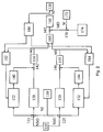
- a corresponding controller structure is shown as a block diagram in FIG. Already described in Figure 1 elements are designated by corresponding reference numerals.
- the output signal NI of the rotational speed sensor 110 passes via a first node 115 to a first P component 120 and a first I component 122. Furthermore, this signal passes via a second node 125 to a second P component 130 and a second I component 132nd
- At the second input of the first node 115 is a first output signal NSO a setpoint input 135, and at the second node 125 is the output signal NSO the setpoint input 135 at.
- the output signal of the first integral component 122 passes through a first limiter 140 to a node 142. At the second input of the node 142 is the output of the first P-portion 120.
- the output of the second integral portion 132 passes through a second limiter 144 to a node 146, at the second input, the output signal of the second proportional component 130 is present.
- the output signal of the connection point 142 is applied to a first manipulated variable limiter 150 whose output signal MO reaches an interlocking 160.
- the output signal of the connection point 146 is applied to a second manipulated variable limiter 155, whose output signal MU likewise arrives at the interlocking 160.
- the output signal of the circuit 160 passes through a node 162 to the signal limit 165, with the output signal M, the actuator 130 is acted upon or from which a signal for acting on the control element 130 is calculated.
- At the second input of the node 162 is the output of a node 170, which is acted upon on the one hand with the output signal W of a weighting instruction 172 and on the other with the signal of a differential component 174.
- the output signal of the control variable limit 165 also arrives at a starting value specification 180, which in turn acts on a first starting value specification 182 and a second starting value specification 184.
- the first starting value input 182 is further supplied with the output signal MO of the first manipulated variable limiting. Accordingly, the second starting value input 184, the output signal MU of the second control variable limit 155 is supplied.
- the integral component 122, the first limiter 140 and the proportional component 120 form a first regulator which regulates the rotational speed to the upper interval limit NSO.
- the manipulated variable limiter 150 limits the output signal of this controller to negative values, ie. H. this controller has only one moment reducing intervention. Ie. the upper limit of this limiter assumes the value 0.
- the proportional component (P component) 130 and the integral component (I component) 132 and the second limiter 144 form a second controller which regulates the rotational speed to the lower interval limit NSU.
- the limiter 155 is designed such that this regulator can only perform a torque-increasing intervention, ie the output signal MU of this regulator branch is limited such that the smallest possible value is 0.
- connection 160 selects the corresponding manipulated variable on the basis of these two manipulated variables MU and MO. This is corrected in the node 162 with the weighted output signal of a D component 174.
- the use of the D component 174 results in improved control quality. Especially with setpoint jumps or transient response at an interval limit, this D component has a positive effect on the control behavior. This correction takes place only in selected operating states.
- the following procedure is used for connecting the control inputs of the parallel control loops.
- path is dynamically switched, ie used to control the control element, which has the magnitude greater change.
- the integrator of the respective other path is set by the corresponding starting value specification 182 or 184 such that the current one Control deviation last represents effective intervention again.
- the inactive path is thus virtually frozen.
- a first step 300 the manipulated variable MO of the first path is determined by the blocks 120, 122, 140 and 142 and the manipulated variable MU of the second path is determined by the blocks 130, 132, 144 and 146.
- step 310 in each case the difference DMO between the new manipulated variable MO and the manipulated variable MOA calculated during the last calculation is determined. Accordingly, the difference DMO of the second control loop is determined on the basis of the current value MU and the preceding MUA.
- the subsequent query 320 checks whether the difference DMO of the first control loop is greater than 0, ie. H. whether the manipulated variable MO increases. If this is not the case, d. H.
- step 340 checks whether the difference DMU is greater than 0. Ie. It is checked whether the controlled variable of the second control loop also increases. If this is the case, d. H. If the first manipulated variable drops and the second manipulated variable increases, step 340 follows. If query 330 recognizes that second manipulated variable DMO likewise drops, that is to say less than 0, step 350 follows. Interrogation 320 recognizes that the first manipulated variable is increasing , d. H. the difference DMO is greater than 0, then the query 335 follows, which checks whether the difference DMU of the second manipulated variable is greater than 0. If this is the case, d. H. The second manipulated variable DMO increases, so also follows step 350. If the second manipulated variable is less than 0, d. H. the first manipulated variable increases and the second manipulated variable decreases, also follows step 340.
- step 340 follows. That means the two manipulated variables are added to the output size M. If the manipulated variables are not in opposite directions, ie both manipulated variables increase or both manipulated variables drop, then in step 350 the magnitude of the change of the manipulated variables is determined in each case.
- the quantity BMO corresponding to the amount of the quantity DMO and the size BMU corresponding to the amount of the quantity DMU are determined.
- Query 360 checks to see if size BMO is greater than size BMU.
- the manipulated variable MO of the first control loop is used for control in step 370.
- the 1-part of the second control loop is frozen to its previous value, ie the I-part is set with the value MUA.
- the manipulated variable of the second control loop is used for control in step 380 and the I-portion 122 of the first control loop is occupied by the value MOA.
- the manipulated variable is used with the magnitude largest change for driving when both controllers provide a manipulated variable.
- the D component 174 is active only in certain operating states. When the D component 174 is switched off, its intervention is taken over by the I components 122 and / or 132 in order to ensure a jump-free course of the manipulated variable M.
- the distribution of the manipulated variable of the D component 174 on the parallel paths is carried out by the starting value specification 180.
- the procedure is as follows: First, it is checked whether the manipulated variable MD of the D component, in particular the weighted manipulated variable, is greater or less than zero. If the manipulated variable MD is greater than 0, then the integral component 122 is assigned as much of MD as possible because of the upper limit 0. The remainder is assigned to integral 132.
- the control concept described is generally applicable to systems that have a controlling intervention on the manipulated variable of the controller.
- the procedure is not limited to a speed control. This can also be used with other regulations.
- switching according to block 160 other strategies are conceivable. For example, a changeover of the two paths can not take place as a function of the magnitude of the manipulated variable, but as a function of the control deviations, in particular the amount of control deviations.
- the functionality in particular when using a computer, can be achieved by the multiple calculation of a path with different parameters and / or limit values.
- the initialization in block 180 other strategies are conceivable. It can be provided that quantities increasing interventions in the second path, ie in particular in the integrator 132 are taken over. Accordingly, for torque-reducing interventions in the first path, in particular in the integral I portion 122 are adopted. Preferably, the initialization will be so carried out that no path as possible reaches the area of the boundary.
- control structures can also be used, in particular with additional proportions or alternative proportions.
- the manipulated variable is the moment.
- other quantities representing the moment may be used.
- the approach can be done on the injection quantity, the throttle position, the firing angle for the rack position or slide path position in edge-controlled systems.
Abstract
Description
Die Erfindung betrifft ein Verfahren und eine Vorrichtung zur Regelung der Drehzahl der Brennkraftmaschine.The invention relates to a method and a device for controlling the speed of the internal combustion engine.
Verfahren und Vorrichtungen zur Regelung der Drehzahl der Brennkraftmaschine, sind bekannt. Bei solchen Systemen wirken üblicherweise wenigstens ein Leerlaufregler und eine Stellgröße, die vom Fahrerwunsch, der über eine Fahrpedalstellung erfasst wird, zusammen. Dabei wirken eine Steuergröße, die dem Fahrerwunschmoment entspricht, das ausgehend von der Fahrpedalstellung vorgegeben wird, und eine Stellgröße eines Reglers, der dem Moment des Leerlaufreglers entspricht, zusammen. Dabei soll die Steuergröße, d. h. das Fahrerwunschmoment, den Leerlaufregler, d. h. das Moment des Leerlaufreglers, überdrücken. Überdrücken bedeutet, dass der Leerlaufregler keine Auswirkung auf die Regelgröße besitzt, wenn das Fahrerwunschmoment größer als das Moment des Leerlaufreglers ist. Dadurch wird eine Erhöhung der Drehzahl möglich, wenn der Fahrer Gas gibt. Andererseits soll der Regler ein Unterschreiten der Leerlaufdrehzahl verhindern. In diesem Fall, wenn der Fahrer kein Gas gibt, überdrückt der Regler die Steuergröße.Methods and apparatus for controlling the speed of the internal combustion engine are known. In such systems, usually at least one idle controller and a manipulated variable, which together from the driver's request, which is detected via an accelerator pedal position. In this case, a control variable, which corresponds to the driver's desired torque, which is predetermined based on the accelerator pedal position, and a manipulated variable of a controller, which corresponds to the moment of the idle controller together. In this case, the control variable, d. H. the driver command torque, the idle controller, d. H. the moment of the idle controller, overpress. Override means that the idle controller has no effect on the control variable when the driver's desired torque is greater than the idle controller's torque. This makes it possible to increase the speed when the driver accelerates. On the other hand, the controller should prevent falling below the idle speed. In this case, if the driver does not throttle, the controller overrides the control quantity.
Die DE 40 16 018 C1 beschreibt eine Schaltungsanordnung zur Prozessregelung, insbesondere zur Regelung eines Durchflusses. Hierbei tritt die Problematik auf, dass die Istwerterfassung einen großen Messbereich abdeckt, wobei der entsprechende Sensor in unterschiedlichen Messbereichen unterschiedliche Genauigkeiten aufweist, d. h. um eine genaue Regelung erzielen zu können, werden für unterschiedliche Messbereiche unterschiedliche Messwertaufnehmer zu erfassen des Istwertes verwendet. Diese beiden Messwerte werden zwei Reglern zugeführt, denen im wesentlichen derselbe Sollwert zugeführt wird. Zur Anpassung an die Eigenschaften der Istwerterfassung, ist vorgesehen, dass in einem Zweig der Sollwert entsprechend gefiltert wird.DE 40 16 018 C1 describes a circuit arrangement for process control, in particular for controlling a flow. In this case, the problem arises that the actual value detection covers a large measuring range, wherein the corresponding sensor has different accuracies in different measuring ranges, ie. H. In order to be able to achieve an exact control, different transducers for detecting the actual value are used for different measuring ranges. These two measured values are fed to two controllers, to which essentially the same reference value is supplied. In order to adapt to the characteristics of the actual value detection, it is provided that the setpoint is filtered accordingly in a branch.
Bei der Regelung der Drehzahl einer Brennkraftmaschine stellt sich die Aufgabe, dass auch bei unterschiedlichen Funktionalitäten, mit Hilfe der Regelung ein zulässiges Drehzahlintervall eingehalten wird, wobei gleichzeitig ein steuernder Eingriff, insbesondere durch den Fahrer, möglich sein soll.In the control of the speed of an internal combustion engine, the task arises that even with different functionalities, with the help of the regulation permissible Speed interval is maintained, at the same time a controlling intervention, in particular by the driver should be possible.
Diese Aufgabe wird dadurch gelöst, dass wenigstens ein erster Regler, ausgehend von einem Vergleich zwischen einem ersten Sollwert und einem Istwert eine erste Stellgröße vorgibt und diese erste Stellgröße derart auf einen ersten Stellbereich begrenzt wird, dass die zu regelnde Größe abnimmt und dass wenigstens ein zweiter Regler, ausgehend von einem Vergleich zwischen einem zweiten Sollwert und dem Istwert eine zweite Stellgröße vorgibt und diese zweite Stellgröße derart auf einen zweiten Stellbereich begrenzt wird, dass die zu regelnde Größe zunimmt.This object is achieved in that at least a first controller, based on a comparison between a first setpoint and an actual value, specifies a first control variable and this first control variable is limited to a first control range such that the variable to be controlled decreases and that at least one second Controller, based on a comparison between a second setpoint and the actual value specifies a second control variable and this second control variable is limited to a second control range such that the variable to be controlled increases.
Das heißt der erste Regler liefert die Stellgrößen nur innerhalb eines bestimmten Stellbereichs. Der zweite Regler liefert die Stellgröße nur innerhalb eines zweiten Stellbereichs. Sowohl der erste als auch der zweiten Regler sind vorzugsweise als Proportionalregler oder als Proportional- und Integralregler ausgebildet. Beim Beispiel eines Drehzahlreglers, der diese über die Kraftstoffmenge regelt, bedeutet dies, dass der erste Regler die Kraftstoffmenge nur verringern und der zweite Regler die Kraftstoffmenge nur erhöhen kann.This means that the first controller only supplies the manipulated variables within a certain setting range. The second controller supplies the manipulated variable only within a second setting range. Both the first and the second controller are preferably designed as a proportional controller or as a proportional and integral controller. In the example of a speed controller, which controls this over the amount of fuel, this means that the first controller can only reduce the amount of fuel and the second controller can only increase the amount of fuel.
Abhängig von den an den Regler gestellten Anforderungen, werden unterschiedliche Sollwerte vorgegeben. Besonders vorteilhaft ist es, wenn die Sollwerte abhängig vom Betriebszustand vorgegeben werden. Dabei ist der erste Sollwert immer größer oder gleich dem zweiten Sollwert.Depending on the demands made on the controller, different setpoints are specified. It is particularly advantageous if the desired values are predefined depending on the operating state. The first setpoint is always greater than or equal to the second setpoint.
Um ein unerwünschtes Verhalten des Regelkreises zu vermeiden, ist für den Fall, dass beide Regler eine Stellgröße bereitstellen vorgesehen, dass die Stellgröße mit der betragsmäßig größten Änderung zur Ansteuerung verwendet wird. In diesem Fall ist besonders vorteilhaft, dass die Stellgröße des anderen Reglers, dass heißt des Reglers mit der betragsmäßig kleinsten Änderung, eingefroren wird.In order to avoid undesirable behavior of the control loop, in the event that both controllers provide a manipulated variable, it is provided that the manipulated variable with the largest change in magnitude is used for actuation. In this case, it is particularly advantageous that the manipulated variable of the other controller, that is, the controller with the absolute smallest change, is frozen.
Von besonderer Bedeutung sind weiterhin die Realisierungen in Form eines Computerprogramms mit Programmcode-Mitteln und in Form eines Computerprogrammprodukts mit Programmcode-Mitteln. Das erfindungsgemäße Computerprogramm weist Programmcode-Mittel auf, um alle Schritte des erfindungsgemäßen Verfahrens durchzuführen, wenn das Programm auf einem Computer, insbesondere einem Steuergerät für eine Brennkraftmaschine eines Kraftfahrzeugs, ausgeführt wird. In diesem Fall wird also die Erfindung durch ein in dem Steuergerät abgespeichertes Programm realisiert, so dass dieses mit dem Programm versehene Steuergerät in gleicher Weise die Erfindung darstellt wie das Verfahren, zu dessen Ausführung das Programm geeignet ist. Das erfindungsgemäße Computerprogrammprodukt weist Programmcode-Mittel auf, die auf einem computerlesbaren Datenträger gespeichert sind, um das erfindungsgemäße Verfahren durchzuführen, wenn das Programmprodukt auf einem Computer, insbesondere einem Steuergerät für eine Brennkraftmaschine eines Kraftfahrzeugs ausgeführt wird. In diesem Fall wird also die Erfindung durch einen Datenträger realisiert, so dass das erfindungsgemäße Verfahren ausgeführt werden kann, wenn das Programmprodukt bzw. der Datenträger in ein Steuergerät für eine Brennkraftmaschine insbesondere eines Kraftfahrzeugs integriert wird. Als Datenträger bzw. als Computerprogrammprodukt kann insbesondere ein elektrisches Speichermedium zur Anwendung kommen, beispielsweise ein Read-Only-Memory (ROM), ein EPROM oder auch ein elektrischer Permanentspeicher wie beispielsweise eine CD-ROM oder DVD.Of particular importance are also the implementations in the form of a computer program with program code means and in the form of a computer program product with program code means. The computer program according to the invention has program code means for carrying out all steps of the method according to the invention when the program is executed on a computer, in particular a control unit for an internal combustion engine of a motor vehicle. In this case, so will the Invention realized by a program stored in the controller, so that this provided with the program control unit in the same way the invention as the method to whose execution the program is suitable. The computer program product according to the invention has program code means which are stored on a computer-readable data carrier in order to carry out the method according to the invention when the program product is executed on a computer, in particular a control unit for an internal combustion engine of a motor vehicle. In this case, therefore, the invention is realized by a data carrier, so that the inventive method can be performed when the program product or the data carrier is integrated into a control device for an internal combustion engine, in particular a motor vehicle. As disk or as Computer program product can be used in particular an electrical storage medium, for example a read-only memory (ROM), an EPROM or a permanent electrical memory such as a CD-ROM or DVD.
Die Erfindung wird nachstehend anhand der in der Zeichnung dargestellten Ausführungsform erläutert.The invention will be explained below with reference to the embodiment shown in the drawing.
Es zeigen
- Figur 1 ein Blockdiagramm der erfindungsgemäßen Vorgehensweise,
- Figur 2 eine detaillierte Darstellung der Regelstruktur und
- Figur 3 ein Flussdiagramm zur Verdeutlichung der erfindungsgemäßen Vorgehensweise.
- FIG. 1 shows a block diagram of the procedure according to the invention,
- Figure 2 is a detailed representation of the control structure and
- FIG. 3 shows a flow chart to clarify the procedure according to the invention.
In Figur 1 ist eine Vorrichtung zur Steuerung einer Brennkraftmaschine dargestellt. Die Brennkraftmaschine ist mit 100 bezeichnet. An der Brennkraftmaschine sind verschiedene Sensoren angeordnet, die verschiedene Signale erfassen. Insbesondere ist ein Drehzahlsensor 110 vorgesehen, der ein Signal NI liefert, das der gemessenen Drehzahl der Brennkraftmaschine entspricht.FIG. 1 shows a device for controlling an internal combustion engine. The internal combustion engine is designated 100. At the internal combustion engine, various sensors are arranged, which detect different signals. In particular, a
Des Weiteren sind an der Brennkraftmaschine 100 verschiedene Stellelemente 120 angeordnet, die die Leistungsabgabe der Brennkraftmaschine und damit die Drehzahl der Brennkraftmaschine beeinflussen. Insbesondere sind Stellelemente 120 vorgesehen, die das von der Brennkraftmaschine bereitgestellte Moment insbesondere über die eingespritzte Kraftstoffmenge steuern.Furthermore, 100
Das Stellelement 120 wird vorzugsweise von einer Steuereinheit 130 mit Ansteuersignalen beaufschlagt. Das Ausgangssignal NI des Sensors 110 gelangt ebenfalls zur Steuereinheit 130. Des Weiteren werden der Steuereinheit 130 Signale weiterer Sensoren 140 zugeleitet. Hierbei handelt es sich insbesondere um ein Signal FP, das den Fahrerwunsch charakterisiert. Hierzu wird insbesondere ein Fahrpedalstellungsgeber verwendet.The
Diese Steuereinheit berechnet ausgehend von dem Fahrerwunsch FP und der Ist-Drehzahl NI ein Ansteuersignal zur Beaufschlagung der Stellelemente 120. Zur Regelung und/oder Steuerung der Drehzahl sind, insbesondere bei Dieselbrennkraftmaschinen ein Leerlaufregler, ein Arbeitsdrehzahlregler, ein Fahrgeschwindigkeitsregler, ein Enddrehzahlregler, eine Höchstgeschwindigkeitsabregelung, ein allgemeiner Drehzahlregler und/oder ein Drehzahlregler vorgesehen. Zur Einhaltung einer Drehzahlobergrenze dienen insbesondere der Enddrehzahlregler, der Arbeitsdrehzahlregler und/oder der Fahrgeschwindigkeitsregler. Der Leerlaufregler gewährleistet, dass die Drehzahl der Brennkraftmaschine nicht unter die Leerlaufdrehzahl abfällt. Der Fahrgeschwindigkeitsregler bewirkt, dass die Drehzahl einen bestimmten Wert, der der gewünschten Fahrgeschwindigkeit entspricht, einhält. Entsprechend gewährleistet der Arbeitsdrehzahlregler, dass die Drehzahl nicht unter eine gewünschte Arbeitsdrehzahl abfällt.Based on the driver's request FP and the actual rotational speed NI, this control unit calculates a drive signal for actuating the
Der Enddrehzahlregler und der Höchstgeschwindigkeitsabregler gewährleisten die Einhaltung einer Drehzahlobergrenze. Der Enddrehzahlregler gewährleistet insbesondere, dass eine höchstzulässige Drehzahl nicht erreicht wird. Die Höchstgeschwindigkeitsabregelung gewährleistet, dass eine Drehzahl, die einer gewünschten Höchstgeschwindigkeit oder einer zulässigen Höchstgeschwindigkeit entspricht, nicht überschritten wird. Der Sonderfall, dass die Drehzahlobergrenze der Drehzahluntergrenze entspricht, ist insbesondere gegeben, wenn bei einem automatisierten Schaltgetriebe, eine für den Schaltvorgang bestimmte Drehzahl durch den allgemeinen Drehzahlregler eingeregelt wird. Entsprechendes gilt auch für einen Drehzahlregler, wenn die Fahrvorgabe des Fahrerwunsches als Solldrehzahl interpretiert wird. Dies gilt insbesondere für spezielle Anwendungen im Nutzfahrzeugbereich.The final speed controller and the maximum speed control ensure compliance with an upper speed limit. The final speed controller ensures in particular that a maximum speed is not reached. The maximum speed reduction ensures that a speed that corresponds to a desired maximum speed or a permissible maximum speed is not exceeded. The special case that the upper speed limit corresponds to the lower speed limit, is given in particular when regulated in an automated transmission, a specific speed for the switching by the general speed controller becomes. The same applies to a speed controller when the driving specification of the driver's request is interpreted as the setpoint speed. This applies in particular to special applications in the commercial vehicle sector.
Üblicherweise wird jede der genannten Funktionalitäten durch einen eigenen Regler realisiert. Diese Regler haben im Allgemeinen unterschiedliche Eingriffspunkte. Probleme treten auf, wenn zeitgleich mehrere Regler im Eingriff sind. Dies führt zu Instabilitäten. Ferner treten Probleme beim Umschalten von einer zur anderen Funktionalität auf. Ein Beispiel ist das Ablösen der Leerlaufregelung durch eine Arbeitsdrehzahlregelung. Hierbei tritt die Problematik auf, dass der Stellereingriff des ersten Reglers geeignet in den zweiten zu übernehmen ist. D. h. die Initialisierung der einzelnen Regler beim Übergang ist problematisch.Usually, each of the mentioned functions is realized by a separate controller. These regulators generally have different engagement points. Problems occur when several controllers are engaged at the same time. This leads to instabilities. Furthermore, problems arise when switching from one to the other functionality. An example is the replacement of idle control by a working speed control. In this case, the problem occurs that the setting intervention of the first controller is suitable to take over in the second. Ie. the initialization of the individual controllers during the transition is problematic.
Erfindungsgemäß wird deshalb ein Drehzahlintervallregler vorgeschlagen, der unabhängig vom steuernden Eingriff der Regler ein Verlassen des Drehzahlintervalles verhindert. Im Sonderfall der Intervallbreite 0 kompensiert der Regler den Steuereingriff zur Einhaltung der Solldrehzahl vollständig. Im allgemeinen Fall einer unendlichen Intervallbreite verhält sich der Regler möglichst neutral, wenn sich die Drehzahl aufgrund des steuernden Eingriffs oder aufgrund anderer Störgrößen innerhalb der Intervallgrenzen befindet. Ein solcher Drehzahlregler ist bei geeigneter Beschaltung der Intervallgrenzen, d. h. bei einer geeigneten Vorgabe der Sollwerte in der Lage, alle oder auch nur einen Teil der oben genannten Funktionalitäten zu realisieren.According to the invention, therefore, a speed interval controller is proposed, which prevents independent of the controlling intervention of the controller leaving the speed interval. In the special case of
Vorteilhaft hierbei ist es, dass Ressourcen sowohl im Steuergerät als auch bei der Entwicklung und der Applikation eingespart werden können, da nur ein Regler benötigt wird. Verbesserungen, die für eine Funktionalität vorgenommen werden, kommen auch den anderen Funktionalitäten zugute. Bei konkurrierenden Funktionalitäten kann eine eindeutige Priorisierung auf Ebene der Sollwertbestimmung erfolgen. Ein überlagerter Eingriff mehrerer Regler ist ausgeschlossen. Die Ablösung einer Funktionalität durch eine andere ist einfacher zu gewährleisten. Eine Initialisierung muß nur bei einem Regler, und nicht bei mehreren Reglern erfolgen.The advantage here is that resources can be saved both in the controller and in the development and the application, since only one controller is needed. Improvements made to one functionality also benefit the other functionality. at Competing functionalities can be clearly prioritized at the level of setpoint determination. A superimposed intervention of several controllers is excluded. The replacement of one functionality by another is easier to ensure. An initialization must only take place with one controller, and not with several controllers.
Erfindungsgemäß ist vorgesehen, dass ein Drehzahlintervallregler durch eine parallele Struktur zweier Regler realisiert wird. Vorzugsweise weisen die zwei parallelen Regler PI-Verhalten auf. Einer der beiden Regler regelt auf eine obere Intervallgrenze als oberen Sollwert NSO ein. Der andere Regler regelt auf die untere Intervallgrenze als unterer Sollwert NSU ein. In jedem der Signalpfade wird der Stelleingriff so begrenzt, dass das zulässige Sollwertintervall nicht verlassen wird.According to the invention, it is provided that a speed interval controller is realized by a parallel structure of two controllers. Preferably, the two parallel controllers have PI behavior. One of the two controllers regulates to an upper interval limit as upper setpoint NSO. The other controller controls the lower interval limit as the lower setpoint NSU. In each of the signal paths, the control intervention is limited so that the permissible setpoint interval is not left.
Unter der Voraussetzung eines positiven Streckenverhaltens, d. h. eine Erhöhung der Stellgröße führt zu einer Erhöhung der Regelgröße, bedeutet dass für die beiden Regelpfade, dass der Reglerpfad für die Drehzahluntergrenze nur erhöhend eingreift. Die Untergrenze seines Stelleingriffes ist damit 0. Als Obergrenze wirkt vorzugsweise der im aktuellen Betriebspunkt zulässige Stelleingriff. Der Reglerpfad für die Drehzahlobergrenze kann nur verringernd eingreifen. Die Obergrenze seines Stelleingriffes ist 0. Als Untergrenze kann beispielsweise der aktuelle Steuerwert für den Stelleingriff dienen. Damit ist sichergestellt, dass bei Überschreiten der oberen Intervallgrenze der steuernde Stelleingriff durch den Reglereingriff aufgehoben werden kann. Durch das Zusammenwirken der beiden Reglerpfade sind sowohl erhöhende wie auch verringernde Eingriffe möglich. Dies gilt auch, wenn die obere und die untere Intervallgrenze gleich sind, d. h. der obere Sollwert NSO und der untere Sollwert NSU sind gleich. Mit diesen Vorgabewerten kann durch die selbe Struktur eine reine Drehzahlregelung realisiert werden. So ist z. B. ein Überdrücken des Steuerwertes bei einer Getriebesteuerung möglich.Assuming a positive path behavior, ie an increase in the manipulated variable leads to an increase in the controlled variable, means that for the two control paths, that the controller path for the lower speed limit only increases increasing. The lower limit of its control intervention is thus 0. The upper limit is preferably the control intervention permissible at the current operating point. The controller path for the upper speed limit can only intervene in a decreasing manner. The upper limit of its control intervention is 0. The lower limit can be, for example, the current control value for the control intervention. This ensures that when the upper interval limit is exceeded, the controlling control intervention can be canceled by the controller intervention. The interaction of the two regulator paths allows both increasing and decreasing interventions. This also applies if the upper and lower interval limits are the same, ie the upper setpoint NSO and the lower setpoint NSU are the same. With these default values can be a pure through the same structure Speed control can be realized. So z. B. an override of the control value in a transmission control possible.
Eine entsprechende Reglerstruktur ist als Blockdiagramm in Figur 2 dargestellt. Bereits in Figur 1 beschriebene Elemente sind mit entsprechenden Bezugszeichen bezeichnet. Das Ausgangssignal NI des Drehzahlsensors 110 gelangt über einen ersten Verknüpfungspunkt 115 zu einem ersten P-Anteil 120 und einem ersten I-Anteil 122. Des Weiteren gelangt dieses Signal über einen zweiten Verknüpfungspunkt 125 zu einem zweiten P-Anteil 130 und einem zweiten I-Anteil 132.A corresponding controller structure is shown as a block diagram in FIG. Already described in Figure 1 elements are designated by corresponding reference numerals. The output signal NI of the
Am zweiten Eingang des ersten Verknüpfungspunktes 115 liegt ein erstes Ausgangssignal NSO einer Sollwertvorgabe 135, und an dem zweiten Verknüpfungspunkt 125 liegt das Ausgangssignal NSO der Sollwertvorgabe 135 an.At the second input of the
Das Ausgangssignal des ersten Integralanteiles 122 gelangt über einen ersten Begrenzer 140 zu einem Verknüpfungspunkt 142. Am zweiten Eingang des Verknüpfungspunktes 142 liegt das Ausgangssignal des ersten P-Anteils 120. Das Ausgangssignal des zweiten Integralanteils 132 gelangt über einen zweiten Begrenzer 144 zu einem Verknüpfungspunkt 146, an dessen zweiten Eingang das Ausgangssignal des zweiten Proportionalanteils 130 anliegt.The output signal of the first
Mit dem Ausgangssignal des Verknüpfungspunktes 142 wird ein erster Stellgrößenbegrenzer 150 beaufschlagt, dessen Ausgangssignal MO zu einer Aufschaltung 160 gelangt. Mit dem Ausgangssignal des Verknüpfungspunktes 146 wird ein zweiter Stellgrößenbegrenzer 155 beaufschlagt, dessen Ausgangssignal MU ebenfalls zur Aufschaltung 160 gelangt. Das Ausgangssignal der Aufschaltung 160 gelangt über einen Verknüpfungspunkt 162 zur Signalbegrenzung 165, mit dessen Ausgangssignal M das Stellelement 130 beaufschlagt wird bzw. ausgehend von dem ein Signal zur Beaufschlagung des Stellelements 130 berechnet wird.The output signal of the
Am zweiten Eingang des Verknüpfungspunktes 162 liegt das Ausgangssignal eines Verknüpfungspunktes 170, das zum Einen mit dem Ausgangssignal W einer Wichtungsvorgabe 172 und zum Anderen mit dem Signal eines Differenzialanteiles 174 beaufschlagt wird.At the second input of the
Das Ausgangssignal der Stellgrößenbegrenzung 165 gelangt ferner zu einer Startwertvorgabe 180, die wiederum eine erste Startwertvorgabe 182 und eine zweite Startwertvorgabe 184 beaufschlagt. Der ersten Startwertvorgabe 182 wird ferner das Ausgangssignal MO der ersten Stellgrößenbegrenzung zugeführt. Entsprechend wird der zweiten Startwertvorgabe 184 das Ausgangssignal MU der zweiten Stellgrößenbegrenzung 155 zugeführt.The output signal of the control
Der Integralanteil 122, der erste Begrenzer 140 und der Proportionalanteil 120 bilden einen ersten Regler, der die Drehzahl auf die obere Intervallgrenze NSO regelt. Dabei begrenzt der Stellgrößenbegrenzer 150 das Ausgangssignal dieses Reglers auf negative Werte, d. h. dieser Regler besitzt lediglich einen das Moment verringernden Eingriff. D. h. der obere Grenzwert dieses Begrenzers nimmt den Wert 0 an.The
Der Proportionalanteil (P-Anteil) 130 und der Integralanteil (I-Anteil) 132 sowie der zweite Begrenzer 144 bilden einen zweiten Regler, der die Drehzahl auf die untere Intervallgrenze NSU regelt. Dabei ist der Begrenzer 155 so ausgebildet, dass dieser Regler nur einen momentenerhöhenden Eingriff durchführen kann, d. h. das Ausgangssignal MU dieses Reglerzweiges ist derart begrenzt, dass der kleinste mögliche Wert 0 beträgt.The proportional component (P component) 130 and the integral component (I component) 132 and the
Die Aufschaltung 160 wählt dann ausgehend von diesen beiden Stellgrößen MU und MO die entsprechende Stellgröße aus. Diese wird im Verknüpfungspunkt 162 mit dem gewichteten Ausgangssignal eines D-Anteiles 174 korrigiert. Durch die Verwendung des D-Anteiles 174 ergibt sich eine verbesserte Regelgüte. Speziell bei Sollwertsprüngen oder Einschwingverhalten an einer Intervallgrenze hat dieser D-Anteil einen positiven Effekt auf das Regelverhalten. Diese Korrektur erfolgt lediglich in ausgewählten Betriebszuständen.The
Bei geringem Abstand zwischen der unteren Intervallgrenze NSO und der oberen Intervallgrenze NSU, d. h. bei kleinen Abständen zwischen dem unteren Sollwert NSU und dem oberen Sollwert NSO, insbesondere wenn die beiden Sollwerte gleich sind, muss in bestimmten Betriebszuständen verhindert werden, dass beide Reglerpfade gleichzeitig dynamisch aktiv sind, d. h. dass beide Reglerpfade einen Momentenwunsch vorgeben. Dies wird mittels der Aufschaltung 160 gewährleistet. Stelleingriffe beider Reglerpfade, insbesondere in gleiche Richtung, d. h. mit gleichsinniger Änderung des Stelleingriffs, sind zu vermeiden, da es dadurch zu einer Addition beider Reglerverstärkungen kommt. Bei entsprechender Auslegung jedes Reglerpfades würde die gleichsinnige Überlagerung beider Reglerpfade aufgrund der zu großen Kreisverstärkung zu einem instabilen Verhalten führen.At a small distance between the lower interval limit NSO and the upper interval limit NSU, d. H. for small distances between the lower setpoint NSU and the upper setpoint NSO, in particular if the two setpoints are the same, it must be prevented in certain operating states that both controller paths are dynamically active at the same time; H. that both controller paths specify a torque request. This is ensured by means of the
Für die Aufschaltung der Stelleingriffe der parallelen Reglerkreise wird folgende Vorgehensweise verwendet. Bei gleichsinnigen Änderungen der Stelleingriffe wird derjenige Pfad dynamisch aufgeschaltet, d. h. zur Ansteuerung des Stellelementes verwendet, welcher die betragsmäßig größere Änderung aufweist. Der Integrator des jeweils anderen Pfades wird durch die entsprechende Startwertvorgabe 182 bzw. 184 derart gesetzt, dass sich der bei der aktuellen Regelabweichung zuletzt wirksame Eingriff wieder darstellt. Der inaktive Pfad wird damit quasi eingefroren.The following procedure is used for connecting the control inputs of the parallel control loops. In the case of changes in the same direction of the control interventions that path is dynamically switched, ie used to control the control element, which has the magnitude greater change. The integrator of the respective other path is set by the corresponding starting
Eine entsprechende Vorgehensweise ist in Figur 3 dargestellt.A corresponding procedure is shown in FIG.
In einem ersten Schritt 300 werden von den Blöcken 120, 122, 140 und 142 die Stellgröße MO des ersten Pfades und von den Blöcken 130, 132, 144 und 146 die Stellgröße MU des zweiten Pfades bestimmt. Anschließend in Schritt 310 wird jeweils die Differenz DMO zwischen der neuen Stellgröße MO und die bei der letzten Berechnung berechneten Stellgröße MOA bestimmt. Entsprechend wird die Differenz DMO des zweiten Regelkreises, ausgehend von dem aktuellen Wert MU und dem vorangegangenen MUA bestimmt. Die sich anschließende Abfrage 320 überprüft, ob die Differenz DMO des ersten Regelkreises größer 0 ist, d. h. ob die Stellgröße MO ansteigt. Ist dies nicht der Fall, d. h. die Regelgröße fällt ab, so überprüft die Abfrage 330, ob die Differenz DMU größer 0 ist. D. h. es wird überprüft, ob die Regelgröße des zweiten Regelkreises ebenfalls ansteigt. Ist dies der Fall, d. h. die erste Stellgröße fällt ab und die zweite Stellgröße steigt an, so folgt Schritt 340. Erkennt die Abfrage 330, dass die zweite Stellgröße DMO ebenfalls abfällt, also kleiner 0 ist, so folgt Schritt 350. Erkennt die Abfrage 320, dass die erste Stellgröße ansteigt, d. h. die Differenz DMO ist größer 0, so folgt die Abfrage 335, die überprüft, ob die Differenz DMU der zweiten Stellgröße größer 0 ist. Ist dies der Fall, d. h. auch die zweite Stellgröße DMO steigt an, so folgt ebenfalls Schritt 350. Ist die zweite Stellgröße kleiner 0, d. h. die erste Stellgröße steigt an und die zweite Stellgröße fällt ab, folgt ebenfalls Schritt 340.In a
Dies bedeutet, sind die Änderungen der Stelleingriffe gegensinnig, d. h. die eine steigt an und die andere fällt ab, so folgt Schritt 340. Das heißt die beiden Stellgrößen werden zur Ausgangsgröße M addiert. Sind die Stellgrößen nicht gegensinnig, d. h. beide Stellgrößen steigen an bzw. beide Stellgrößen fallen ab, so wird in Schritt 350 jeweils der Betrag der Änderung der Stellgrößen bestimmt. Vorzugsweise werden die Größe BMO, die dem Betrag der Größe DMO entspricht, und die Größe BMU, die dem Betrag der Größe DMU entspricht, bestimmt. Die Abfrage 360 überprüft, ob die Größe BMO größer als die Größe BMU ist. Ist dies der Fall, d. h. der Betrag der Änderung der Stellgröße des ersten Regelkreises ist größer als der Betrag der Änderung des zweiten Regelkreises, so wird die Stellgröße MO des ersten Regelkreises in Schritt 370 zur Steuerung verwendet. Gleichzeitig wird der 1-Anteil des zweiten Regelkreises auf seinen vorhergehenden Wert eingefroren, d. h. der I-Anteil wird mit dem Wert MUA gesetzt.This means that the changes of the control interventions are in opposite directions, ie the one increases and the other drops off, then step 340 follows. That means the two manipulated variables are added to the output size M. If the manipulated variables are not in opposite directions, ie both manipulated variables increase or both manipulated variables drop, then in
Entsprechend wird, wenn die Größe BMO nicht größer ist als die Größe BMU, d. h. der Betrag der Änderung der zweiten Stellgröße ist größer als der Betrag der Änderung der ersten Stellgröße, so wird die Stellgröße des zweiten Regelkreises in Schritt 380 zur Steuerung verwendet und der I-Anteil 122 des ersten Regelkreises mit dem Wert MOA besetzt.Accordingly, if the size BMO is not larger than the size BMU, d. H. the amount of change of the second manipulated variable is greater than the amount of change of the first manipulated variable, the manipulated variable of the second control loop is used for control in
Dies bedeutet bei dieser vorteilhaften Ausgestaltung wird die Stellgröße mit der betragsmäßigen größten Änderung zur Ansteuerung verwendet, wenn beide Regler eine Stellgröße bereitstellen.This means in this advantageous embodiment, the manipulated variable is used with the magnitude largest change for driving when both controllers provide a manipulated variable.
Der D-Anteil 174 ist nur in bestimmten Betriebszuständen aktiv. Beim Abschalten des D-Anteils 174 wird dessen Eingriff durch die I-Anteile 122 und/oder 132 übernommen, um einen sprungfreien Verlauf der Stellgröße M zu gewährleisten.The
Die Aufteilung der Stellgröße des D-Anteils 174 auf die parallelen Pfade erfolgt durch die Startwertvorgabe 180.The distribution of the manipulated variable of the
Hierzu wird wie folgt vorgegangen: Zuerst wird überprüft, ob die Stellgröße MD des D-Anteils, insbesondere die gewichtete Stellgröße größer oder kleiner 0 ist. Ist die Stellgröße MD größer 0, so wird dem Integralanteil 122 so viel von MD zugewiesen, wie dies aufgrund der oberen Grenze 0 möglich ist. Der verbleibende Rest wird dem Integralanteil 132 zugewiesen.The procedure is as follows: First, it is checked whether the manipulated variable MD of the D component, in particular the weighted manipulated variable, is greater or less than zero. If the manipulated variable MD is greater than 0, then the
Das beschriebene Regelkonzept ist allgemein einsetzbar auf Systeme, die einen steuernden Eingriff auf die Stellgröße des Reglers aufweist. Dabei ist die Vorgehensweise nicht auf eine Drehzahlregelung beschränkt. Die kann auch bei anderen Regelungen verwendet werden. Bei der Aufschaltung gemäß Block 160 sind auch andere Strategien denkbar. Z. B. kann eine Umschaltung der beiden Pfades nicht in Abhängigkeit des Betrages der Stellgröße, sondern in Abhängigkeit der Regelabweichungen, insbesondere dem Betrag der Regelabweichungen, erfolgen.The control concept described is generally applicable to systems that have a controlling intervention on the manipulated variable of the controller. The procedure is not limited to a speed control. This can also be used with other regulations. When switching according to block 160, other strategies are conceivable. For example, a changeover of the two paths can not take place as a function of the magnitude of the manipulated variable, but as a function of the control deviations, in particular the amount of control deviations.
Instabilitäten beim gleichzeitigen Eingriff beider paralleler Pfade können auch durch ausgezeichnete Parameter, beispielsweise geringere Verstärkungsfaktoren oder durch eine dynamische Entkopplung vermieden werden.Instabilities in the simultaneous engagement of both parallel paths can also be avoided by excellent parameters, such as lower gain factors or by a dynamic decoupling.
Anstelle zweier paralleler Pfade kann die Funktionalität, insbesondere bei der Verwendung eines Rechners, durch die mehrfache Berechnung eines Pfads mit unterschiedlichen Parametern und/oder Grenzwerten erfolgen.Instead of two parallel paths, the functionality, in particular when using a computer, can be achieved by the multiple calculation of a path with different parameters and / or limit values.
Für die Initialisierung im Block 180 sind auch andere Strategien denkbar. Es kann vorgesehen sein, dass mengenerhöhende Eingriffe in den zweiten Pfad, d. h. insbesondere in den Integrator 132 übernommen werden. Entsprechend werden für momentenverringernde Eingriffe in den ersten Pfad, insbesondere in den Integral-I-Anteil 122 übernommen. Vorzugsweise wird die Initialisierung so durchgeführt, dass möglichst kein Pfad in den Bereich der Begrenzung gelangt.For the initialization in
Anstelle der PI-Regler können auch andere Regelstrukturen insbesondere mit zusätzlichen Anteilen oder alternativen Anteilen verwendet werden.Instead of the PI controllers, other control structures can also be used, in particular with additional proportions or alternative proportions.
Im beschriebenen Ausführungsbeispiel handelt es sich bei der Stellgröße um das Moment. Anstelle dieser Größe können auch andere Größen, die das Moment repräsentieren, verwendet werden. Insbesondere kann die Vorgehensweise auf die Einspritzmenge, die Drosselklappenstellung, den Zündwinkel für die Regelstangenposition oder Schieberwegposition bei kantengesteuerten Systemen erfolgen.In the described embodiment, the manipulated variable is the moment. Instead of this size, other quantities representing the moment may be used. In particular, the approach can be done on the injection quantity, the throttle position, the firing angle for the rack position or slide path position in edge-controlled systems.
Claims (7)
- Method for controlling the speed of an internal combustion engine, having at least one first controller (120, 122, 140) which predefines a first manipulated variable (MO) on the basis of a comparison (115) between a first set point value (NSO) and an actual value (NI), having at least one second controller (130, 132, 144) which predefines a second manipulated variable (MU) on the basis of a comparison (125) between a second set point value (NSU) and the actual value (NI), characterized in that the first manipulated variable (MO) is limited to a first actuating range in such a way that the variable to be controlled decreases, and in that the second manipulated variable (MU) is limited to a second actuating range in such a way that the variable to be controlled increases.
- Method according to Claim 1 or 2, characterized in that the first set point value (NSO) is greater than or equal to the second set point value (NSU).
- Method according to one of the preceding claims, characterized in that if both controllers (120, 122, 140, 130, 132, 144) make available a manipulated variable (MU, MO), the manipulated variable (MU, MO) with the greatest change in absolute terms is used for the actuation.
- Method according to Claim 4, characterized in that the manipulative variable with the smallest change in absolute terms is frozen.
- Method according to one of the preceding claims, characterized in that in specific operating states the manipulated variable is additionally influenced by a controller (172) having at least a differential behaviour.
- Device for controlling the speed of an internal combustion engine, having at least one first controller (120, 122, 140) which predefines a first manipulated variable (MO) on the basis of a comparison (115) between a first set point value (NSO) and an actual value (NI), having at least one second controller (130, 132, 144) which predefines a second manipulated variable (MU) on the basis of a comparison (125) between a second set point value (NSU) and the actual value (NI), characterized in that means (150, 155) are provided which limit the first manipulated variable (MO) to a first actuating range in such a way that the variable to be controlled decreases and which limit the second manipulated variable (MU) to a second actuating range in such a way that the variable to be controlled increases.
- Computer program having program code means for applying a method for operating an internal combustion engine according to at least one of Claims 1 to 6, all the steps being carried out by any of the Claims 1 to 6 if the program is executed on a computer, in particular a control unit.
Applications Claiming Priority (3)
| Application Number | Priority Date | Filing Date | Title |
|---|---|---|---|
| DE10205375A DE10205375A1 (en) | 2002-02-09 | 2002-02-09 | Method and device for controlling an internal combustion engine, in particular for regulating the speed of the internal combustion engine |
| DE10205375 | 2002-02-09 | ||
| PCT/DE2002/004311 WO2003067342A1 (en) | 2002-02-09 | 2002-11-25 | Method and device for controlling the speed of an internal combustion engine |
Publications (2)
| Publication Number | Publication Date |
|---|---|
| EP1478986A1 EP1478986A1 (en) | 2004-11-24 |
| EP1478986B1 true EP1478986B1 (en) | 2007-05-09 |
Family
ID=27618491
Family Applications (1)
| Application Number | Title | Priority Date | Filing Date |
|---|---|---|---|
| EP02787391A Expired - Lifetime EP1478986B1 (en) | 2002-02-09 | 2002-11-25 | Method and device for controlling the speed of an internal combustion engine |
Country Status (6)
| Country | Link |
|---|---|
| US (1) | US6925985B2 (en) |
| EP (1) | EP1478986B1 (en) |
| JP (1) | JP4225916B2 (en) |
| CN (1) | CN1302346C (en) |
| DE (2) | DE10205375A1 (en) |
| WO (1) | WO2003067342A1 (en) |
Cited By (1)
| Publication number | Priority date | Publication date | Assignee | Title |
|---|---|---|---|---|
| DE102010001696A1 (en) * | 2010-02-09 | 2011-08-11 | ZF Friedrichshafen AG, 88046 | Method for adjusting driver desire-dependent target rotation speed of transmission output shaft in stepless transmission device of construction site car, involves determining target speed from difference between upper limit and offset-value |
Families Citing this family (10)
| Publication number | Priority date | Publication date | Assignee | Title |
|---|---|---|---|---|
| DE102005042650B4 (en) * | 2005-09-08 | 2017-10-12 | Robert Bosch Gmbh | Speed control for an internal combustion engine in the event of a fall in gas |
| DE102007045195B3 (en) * | 2007-09-21 | 2009-03-12 | Mtu Friedrichshafen Gmbh | Method for controlling a stationary gas engine |
| US7983812B2 (en) * | 2008-08-04 | 2011-07-19 | Scott Potter & Associates, Llc | Method and apparatus for managing battery power in emergency vehicles |
| DE102010003539A1 (en) | 2010-03-31 | 2011-10-06 | Robert Bosch Gmbh | Method and circuit arrangement for determining position-minus time |
| US9823629B2 (en) | 2010-11-16 | 2017-11-21 | Siemens Aktiengesellschaft | Dual loop control system with interactive automatic tracking mode |
| DE102011078609A1 (en) * | 2011-07-04 | 2013-01-10 | Robert Bosch Gmbh | Method for operating an internal combustion engine |
| US9850841B2 (en) * | 2013-12-11 | 2017-12-26 | General Electric Company | System and program product for controlling exhaust gas temperature of engine system |
| DE102015208687B4 (en) | 2015-05-11 | 2021-07-15 | Robert Bosch Gmbh | Method for determining a total mass moment of inertia of a drive train |
| CN107463717A (en) * | 2016-06-03 | 2017-12-12 | 罗伯特·博世有限公司 | For the method for the gross mass the moment of inertia for asking for power train |
| DE102017200839A1 (en) * | 2017-01-19 | 2018-07-19 | Robert Bosch Gmbh | Method for controlling a rotational speed of an electrical machine |
Family Cites Families (15)
| Publication number | Priority date | Publication date | Assignee | Title |
|---|---|---|---|---|
| GB1416861A (en) * | 1971-12-03 | 1975-12-10 | Cav Ltd | Control systems for internal combustion engines |
| DE3114836A1 (en) * | 1981-04-11 | 1982-11-04 | Robert Bosch Gmbh, 7000 Stuttgart | CONTROL SYSTEM FOR AN INTERNAL COMBUSTION ENGINE |
| US4422420A (en) * | 1981-09-24 | 1983-12-27 | Trw Inc. | Method and apparatus for fuel control in fuel injected internal combustion engines |
| DE3202614A1 (en) * | 1982-01-27 | 1983-08-04 | Robert Bosch Gmbh, 7000 Stuttgart | CONTROL DEVICE FOR STARTING A SPRAYER ON AN INTERNAL COMBUSTION ENGINE |
| JPS60190641A (en) * | 1984-03-12 | 1985-09-28 | Diesel Kiki Co Ltd | Electronic type governor for internal-combustion engine |
| DE58908423D1 (en) * | 1989-07-07 | 1994-10-27 | Siemens Ag | METHOD AND DEVICE FOR SPEED CONTROL OF A SLOW-RUNNING, MULTI-CYLINDRICAL DIESEL ENGINE. |
| DE4016018C1 (en) * | 1990-05-18 | 1991-08-08 | Eckardt Ag, 7000 Stuttgart, De | Process regulating circuitry using two measurers in parallel - has range selection stage cooperating with proportional member and lowest and highest value limiting stages |
| DE59208400D1 (en) | 1992-02-04 | 1997-05-28 | Siemens Ag | Process for controlling technical processes with several controllers |
| US5417193A (en) * | 1994-01-25 | 1995-05-23 | Textron Inc. | Engine speed control system and method |
| DE19620039A1 (en) * | 1996-05-17 | 1997-11-20 | Bosch Gmbh Robert | System for controlling an internal combustion engine |
| DE19711787A1 (en) * | 1996-05-29 | 1997-12-04 | Bosch Gmbh Robert | Method and device for regulating an internal combustion engine |
| US6334424B1 (en) * | 1999-03-05 | 2002-01-01 | Toyota Jidosha Kabushiki Kaisha | Control device and control method for vehicle |
| US6539299B2 (en) * | 2000-02-18 | 2003-03-25 | Optimum Power Technology | Apparatus and method for calibrating an engine management system |
| US6363906B1 (en) * | 2000-03-06 | 2002-04-02 | Detroit Diesel Corporation | Idle shutdown override with defeat protection |
| US6678608B2 (en) * | 2001-11-09 | 2004-01-13 | Ford Global Technologies, Llc | Robust interpolation method for improved automative engine control during transient engine operation |
-
2002
- 2002-02-09 DE DE10205375A patent/DE10205375A1/en not_active Withdrawn
- 2002-11-25 WO PCT/DE2002/004311 patent/WO2003067342A1/en active IP Right Grant
- 2002-11-25 JP JP2003566631A patent/JP4225916B2/en not_active Expired - Fee Related
- 2002-11-25 CN CNB028116143A patent/CN1302346C/en not_active Expired - Fee Related
- 2002-11-25 EP EP02787391A patent/EP1478986B1/en not_active Expired - Lifetime
- 2002-11-25 US US10/473,510 patent/US6925985B2/en not_active Expired - Lifetime
- 2002-11-25 DE DE50210139T patent/DE50210139D1/en not_active Expired - Lifetime
Non-Patent Citations (1)
| Title |
|---|
| None * |
Cited By (1)
| Publication number | Priority date | Publication date | Assignee | Title |
|---|---|---|---|---|
| DE102010001696A1 (en) * | 2010-02-09 | 2011-08-11 | ZF Friedrichshafen AG, 88046 | Method for adjusting driver desire-dependent target rotation speed of transmission output shaft in stepless transmission device of construction site car, involves determining target speed from difference between upper limit and offset-value |
Also Published As
| Publication number | Publication date |
|---|---|
| US20040149259A1 (en) | 2004-08-05 |
| WO2003067342A1 (en) | 2003-08-14 |
| EP1478986A1 (en) | 2004-11-24 |
| DE50210139D1 (en) | 2007-06-21 |
| JP4225916B2 (en) | 2009-02-18 |
| DE10205375A1 (en) | 2003-08-21 |
| US6925985B2 (en) | 2005-08-09 |
| JP2005517128A (en) | 2005-06-09 |
| CN1302346C (en) | 2007-02-28 |
| CN1514961A (en) | 2004-07-21 |
Similar Documents
| Publication | Publication Date | Title |
|---|---|---|
| DE3416369C2 (en) | Vehicle speed control device | |
| DE4219791C2 (en) | System for regulating the charging of an internal combustion engine | |
| DE3333392A1 (en) | METHOD FOR FEEDBACK CONTROL OF THE IDLE SPEED OF AN INTERNAL COMBUSTION ENGINE | |
| WO1997043531A1 (en) | Method and device for controlling an internal combustion engine | |
| EP0763167A1 (en) | Method for controlling/regulating processes in motor vehicles | |
| DE102007009688A1 (en) | Method for determining gradient limiting target torque, involves determining gradient limiting target torque from requested target drive torque and regulating drive torque of speed regulation | |
| EP1478986B1 (en) | Method and device for controlling the speed of an internal combustion engine | |
| EP1896709B1 (en) | Method and apparatus for controlling an internal combustion engine | |
| DE4333896B4 (en) | Method and device for controlling an internal combustion engine | |
| DE10114040B4 (en) | Method and device for controlling the drive unit of a vehicle | |
| DE10302263B3 (en) | Internal combustion engine revolution rate regulation involves using different characteristics for input parameter in different engine modes, changing between characteristics when condition fulfilled | |
| WO2007090216A2 (en) | Method for controlling the air system in an internal combustion engine | |
| DE4223253C2 (en) | Control device for a vehicle | |
| DE4115647B4 (en) | Control system in a vehicle | |
| WO2001079676A1 (en) | Method and device for the operation of a drive unit on a vehicle | |
| DE19924862C1 (en) | Method for adjusting a preset target speed in a vehicle with a steady rate of fuel operates one branch for full operating of fuel with all cylinders firing and another branch for partial cut-out with a portion of cylinders firing | |
| WO2001073281A1 (en) | Method and device for controlling the drive unit of a motor vehicle | |
| EP2729688A1 (en) | Method for operating an internal combustion engine | |
| EP1309784B1 (en) | Method and device for regulating an operating variable of an internal combustion engine | |
| DE10156948B4 (en) | Method and device for controlling a drive unit of a vehicle | |
| DE4123347B4 (en) | Device for regulating the speed of a motor vehicle | |
| DE102007062173A1 (en) | Internal-combustion engine operating method for motor vehicle, involves determining maximum and momentary moments and pre-determining reference values of idle speed in dependent of maximum and momentary moments of engine | |
| WO2009013256A1 (en) | Method and apparatus for operating a drive unit | |
| WO2023135112A1 (en) | Method with a hydraulic pressure medium supply arrangement, and hydraulic pressure medium supply arrangement | |
| EP1507966B1 (en) | Method and device for regulating an operational characteristic variable in a motor vehicle |
Legal Events
| Date | Code | Title | Description |
|---|---|---|---|
| PUAI | Public reference made under article 153(3) epc to a published international application that has entered the european phase |
Free format text: ORIGINAL CODE: 0009012 |
|
| 17P | Request for examination filed |
Effective date: 20040909 |
|
| AK | Designated contracting states |
Kind code of ref document: A1 Designated state(s): AT BE BG CH CY CZ DE DK EE ES FI FR GB GR IE IT LI LU MC NL PT SE |
|
| GRAP | Despatch of communication of intention to grant a patent |
Free format text: ORIGINAL CODE: EPIDOSNIGR1 |
|
| RBV | Designated contracting states (corrected) |
Designated state(s): DE FR GB IT SE |
|
| GRAS | Grant fee paid |
Free format text: ORIGINAL CODE: EPIDOSNIGR3 |
|
| GRAA | (expected) grant |
Free format text: ORIGINAL CODE: 0009210 |
|
| AK | Designated contracting states |
Kind code of ref document: B1 Designated state(s): DE FR GB IT SE |
|
| REG | Reference to a national code |
Ref country code: GB Ref legal event code: FG4D Free format text: NOT ENGLISH |
|
| REF | Corresponds to: |
Ref document number: 50210139 Country of ref document: DE Date of ref document: 20070621 Kind code of ref document: P |
|
| REG | Reference to a national code |
Ref country code: SE Ref legal event code: TRGR |
|
| GBT | Gb: translation of ep patent filed (gb section 77(6)(a)/1977) |
Effective date: 20070815 |
|
| ET | Fr: translation filed | ||
| PLBE | No opposition filed within time limit |
Free format text: ORIGINAL CODE: 0009261 |
|
| STAA | Information on the status of an ep patent application or granted ep patent |
Free format text: STATUS: NO OPPOSITION FILED WITHIN TIME LIMIT |
|
| 26N | No opposition filed |
Effective date: 20080212 |
|
| PGFP | Annual fee paid to national office [announced via postgrant information from national office to epo] |
Ref country code: GB Payment date: 20141120 Year of fee payment: 13 Ref country code: SE Payment date: 20141120 Year of fee payment: 13 |
|
| PGFP | Annual fee paid to national office [announced via postgrant information from national office to epo] |
Ref country code: FR Payment date: 20141118 Year of fee payment: 13 |
|
| PGFP | Annual fee paid to national office [announced via postgrant information from national office to epo] |
Ref country code: IT Payment date: 20141125 Year of fee payment: 13 |
|
| GBPC | Gb: european patent ceased through non-payment of renewal fee |
Effective date: 20151125 |
|
| PG25 | Lapsed in a contracting state [announced via postgrant information from national office to epo] |
Ref country code: IT Free format text: LAPSE BECAUSE OF NON-PAYMENT OF DUE FEES Effective date: 20151125 |
|
| REG | Reference to a national code |
Ref country code: FR Ref legal event code: ST Effective date: 20160729 |
|
| PG25 | Lapsed in a contracting state [announced via postgrant information from national office to epo] |
Ref country code: SE Free format text: LAPSE BECAUSE OF NON-PAYMENT OF DUE FEES Effective date: 20151126 |
|
| PG25 | Lapsed in a contracting state [announced via postgrant information from national office to epo] |
Ref country code: GB Free format text: LAPSE BECAUSE OF NON-PAYMENT OF DUE FEES Effective date: 20151125 |
|
| PG25 | Lapsed in a contracting state [announced via postgrant information from national office to epo] |
Ref country code: FR Free format text: LAPSE BECAUSE OF NON-PAYMENT OF DUE FEES Effective date: 20151130 |
|
| PGFP | Annual fee paid to national office [announced via postgrant information from national office to epo] |
Ref country code: DE Payment date: 20170126 Year of fee payment: 15 |
|
| REG | Reference to a national code |
Ref country code: DE Ref legal event code: R119 Ref document number: 50210139 Country of ref document: DE |
|
| PG25 | Lapsed in a contracting state [announced via postgrant information from national office to epo] |
Ref country code: DE Free format text: LAPSE BECAUSE OF NON-PAYMENT OF DUE FEES Effective date: 20180602 |