EP2641006B1 - Konfektionierte elektrisch beheizbare medienleitung sowie verfahren zum herstellen einer solchen medienleitung - Google Patents
Konfektionierte elektrisch beheizbare medienleitung sowie verfahren zum herstellen einer solchen medienleitung Download PDFInfo
- Publication number
- EP2641006B1 EP2641006B1 EP11791433.3A EP11791433A EP2641006B1 EP 2641006 B1 EP2641006 B1 EP 2641006B1 EP 11791433 A EP11791433 A EP 11791433A EP 2641006 B1 EP2641006 B1 EP 2641006B1
- Authority
- EP
- European Patent Office
- Prior art keywords
- pipeline part
- conductors
- connection
- media line
- heating
- Prior art date
- Legal status (The legal status is an assumption and is not a legal conclusion. Google has not performed a legal analysis and makes no representation as to the accuracy of the status listed.)
- Active
Links
Images


Classifications
-
- F—MECHANICAL ENGINEERING; LIGHTING; HEATING; WEAPONS; BLASTING
- F16—ENGINEERING ELEMENTS AND UNITS; GENERAL MEASURES FOR PRODUCING AND MAINTAINING EFFECTIVE FUNCTIONING OF MACHINES OR INSTALLATIONS; THERMAL INSULATION IN GENERAL
- F16L—PIPES; JOINTS OR FITTINGS FOR PIPES; SUPPORTS FOR PIPES, CABLES OR PROTECTIVE TUBING; MEANS FOR THERMAL INSULATION IN GENERAL
- F16L53/00—Heating of pipes or pipe systems; Cooling of pipes or pipe systems
- F16L53/30—Heating of pipes or pipe systems
- F16L53/34—Heating of pipes or pipe systems using electric, magnetic or electromagnetic fields, e.g. induction, dielectric or microwave heating
-
- F—MECHANICAL ENGINEERING; LIGHTING; HEATING; WEAPONS; BLASTING
- F16—ENGINEERING ELEMENTS AND UNITS; GENERAL MEASURES FOR PRODUCING AND MAINTAINING EFFECTIVE FUNCTIONING OF MACHINES OR INSTALLATIONS; THERMAL INSULATION IN GENERAL
- F16L—PIPES; JOINTS OR FITTINGS FOR PIPES; SUPPORTS FOR PIPES, CABLES OR PROTECTIVE TUBING; MEANS FOR THERMAL INSULATION IN GENERAL
- F16L11/00—Hoses, i.e. flexible pipes
- F16L11/04—Hoses, i.e. flexible pipes made of rubber or flexible plastics
- F16L11/12—Hoses, i.e. flexible pipes made of rubber or flexible plastics with arrangements for particular purposes, e.g. specially profiled, with protecting layer, heated, electrically conducting
- F16L11/127—Hoses, i.e. flexible pipes made of rubber or flexible plastics with arrangements for particular purposes, e.g. specially profiled, with protecting layer, heated, electrically conducting electrically conducting
-
- F—MECHANICAL ENGINEERING; LIGHTING; HEATING; WEAPONS; BLASTING
- F16—ENGINEERING ELEMENTS AND UNITS; GENERAL MEASURES FOR PRODUCING AND MAINTAINING EFFECTIVE FUNCTIONING OF MACHINES OR INSTALLATIONS; THERMAL INSULATION IN GENERAL
- F16L—PIPES; JOINTS OR FITTINGS FOR PIPES; SUPPORTS FOR PIPES, CABLES OR PROTECTIVE TUBING; MEANS FOR THERMAL INSULATION IN GENERAL
- F16L53/00—Heating of pipes or pipe systems; Cooling of pipes or pipe systems
- F16L53/30—Heating of pipes or pipe systems
- F16L53/35—Ohmic-resistance heating
- F16L53/38—Ohmic-resistance heating using elongate electric heating elements, e.g. wires or ribbons
-
- F—MECHANICAL ENGINEERING; LIGHTING; HEATING; WEAPONS; BLASTING
- F01—MACHINES OR ENGINES IN GENERAL; ENGINE PLANTS IN GENERAL; STEAM ENGINES
- F01N—GAS-FLOW SILENCERS OR EXHAUST APPARATUS FOR MACHINES OR ENGINES IN GENERAL; GAS-FLOW SILENCERS OR EXHAUST APPARATUS FOR INTERNAL-COMBUSTION ENGINES
- F01N2610/00—Adding substances to exhaust gases
- F01N2610/02—Adding substances to exhaust gases the substance being ammonia or urea
-
- F—MECHANICAL ENGINEERING; LIGHTING; HEATING; WEAPONS; BLASTING
- F01—MACHINES OR ENGINES IN GENERAL; ENGINE PLANTS IN GENERAL; STEAM ENGINES
- F01N—GAS-FLOW SILENCERS OR EXHAUST APPARATUS FOR MACHINES OR ENGINES IN GENERAL; GAS-FLOW SILENCERS OR EXHAUST APPARATUS FOR INTERNAL-COMBUSTION ENGINES
- F01N2610/00—Adding substances to exhaust gases
- F01N2610/10—Adding substances to exhaust gases the substance being heated, e.g. by heating tank or supply line of the added substance
-
- F—MECHANICAL ENGINEERING; LIGHTING; HEATING; WEAPONS; BLASTING
- F01—MACHINES OR ENGINES IN GENERAL; ENGINE PLANTS IN GENERAL; STEAM ENGINES
- F01N—GAS-FLOW SILENCERS OR EXHAUST APPARATUS FOR MACHINES OR ENGINES IN GENERAL; GAS-FLOW SILENCERS OR EXHAUST APPARATUS FOR INTERNAL-COMBUSTION ENGINES
- F01N2610/00—Adding substances to exhaust gases
- F01N2610/14—Arrangements for the supply of substances, e.g. conduits
-
- Y—GENERAL TAGGING OF NEW TECHNOLOGICAL DEVELOPMENTS; GENERAL TAGGING OF CROSS-SECTIONAL TECHNOLOGIES SPANNING OVER SEVERAL SECTIONS OF THE IPC; TECHNICAL SUBJECTS COVERED BY FORMER USPC CROSS-REFERENCE ART COLLECTIONS [XRACs] AND DIGESTS
- Y10—TECHNICAL SUBJECTS COVERED BY FORMER USPC
- Y10T—TECHNICAL SUBJECTS COVERED BY FORMER US CLASSIFICATION
- Y10T29/00—Metal working
- Y10T29/49—Method of mechanical manufacture
- Y10T29/49002—Electrical device making
Definitions
- the invention relates to a prefabricated electrically heatable media line with at least one pipe part with integrated electrically conductive device and with at least one connecting device for fluidic connection, as well as a method for producing such a media line.
- Such electrically heated media lines are known in the prior art.
- the electrically conductive device serves to heat the media line and the connecting device serves to fluidically connect the media line, for example with an aggregate.
- EN 10 2005 037 183 B3 A heatable fluid line with a pipe, at least one heating resistor and at least two electrical supply lines for the heating resistor is known, wherein the electrical supply lines are arranged parallel to the pipe and the heating resistor is arranged transversely to the longitudinal extension between the two electrical supply lines.
- a clamp is provided which has a cutting edge which contacts one electrical supply line. The cutting edge of the clamp penetrates the material of the pipe from the outside to such a depth that the electrical supply line which would otherwise be covered is contacted.
- the electrical supply line is connected to a power supply via the clamp.
- the EN 10 2006 051 413 B4 discloses another possibility of providing an electrically heatable fluid line with electrical connections.
- the fluid line has an inner cross-sectional area that surrounds a medium-conducting channel, a heating conductor arrangement and an outer cross-sectional area.
- the heating conductor arrangement is arranged in a heat-conducting connection with the inner cross-sectional area and the outer cross-sectional area surrounds the heating conductor arrangement.
- an intermediate layer is arranged that separates the heating conductor arrangement from the outer cross-sectional area and that has a lower mechanical stability than the inner cross-sectional area and the outer cross-sectional area.
- the Intermediate layer can be rubbed off to allow contacting of the heating conductor arrangement.
- the outer cross-sectional area can be severed and pulled off the end of the fluid line.
- the outer cross-sectional area is peeled off the intermediate layer after being severed.
- the intermediate layer is removed from the inner cross-sectional area due to its lower stability compared to that of the inner cross-sectional area. Once the intermediate layer is removed, the ends of the heating conductor arrangement are exposed and can be contacted.
- the WO 2010/080890 A1 discloses an electrically heated flexible fluid conduit having an elongated flexible tubular body comprising an electrical resistance heater surrounding the fluid flow path.
- heat-generating electrical flow paths are formed by an electrically conductive wire in the tubular body that is laid around the fluid flow path to cross two electrical supply lines at numerous locations.
- the heat-generating electrical flow path includes a layer of electrically conductive polymers within the tubular body surrounding the fluid flow path. Either the entire tubular body is made of electrically conductive polymers or the polymer layer is sandwiched between two electrically non-conductive layers.
- the electrical supply lines are connected to an electrical power source via electrical connectors, the electrical connectors being located at the same end of the tubular body, at opposite ends, or along the tubular body.
- the DE 20 2005 004 602 U1 discloses a heatable liquid line with electrical lines embedded in the jacket of the liquid line.
- a plastic hose through which liquid flows forms an innermost layer, which is surrounded by a middle layer made of an electrically conductive polymer with positive temperature characteristics of the electrical resistance and electrical lines embedded therein, with an outer layer made of an insulating material surrounding the line on the outside.
- the middle layer is designed as a thermoplastic polymer with electrically conductive particles in the form of a PTC polymer layer extruded onto the innermost layer.
- the present invention is therefore based on the object of providing a simplification and reduction of the manufacturing steps for producing a prefabricated electrically heatable media line, wherein heating of the connecting device enabling a fluid connection with, in particular, an aggregate should also be possible in a simple manner.
- the pipeline part comprises an electrically heatable three-layer plastic pipe with an outer layer, a middle layer and an inner layer, wherein the middle layer of the pipeline part consists of a plastic material filled with at least one conductive component and the pipeline part has at least two electrical conductors or heating conductors extruded into its wall, wherein the at least two electrical conductors or heating conductors are arranged within the conductive layer, and wherein the connecting device is attached or attached to the end region of the pipeline part by primary molding and/or material bonding, and that the pipeline part provided with the electrically conductive device and the electrically conductive device extend up to or close to the distal end of the connecting device facing away from the pipeline part or up to close to, in front of or into a connection contour of an aggregate or an aggregate plug inserted into the connecting device in order to enable the connecting device to be completely heated without additional heating conductors on the outside of the connecting device.
- a pipeline part with a three-layer wall of the pipeline part is manufactured with at least one electrically conductive device designed as a heat or cold conductor integrated into it and is provided with at least one connecting device in the end region, and in at least one end region of the pipeline part the integrated conductive device is exposed, permanently electrically contacted by a contacting device and the contacting device is led out to the outside of the pipeline part for connection to an electrical energy source.
- An integrated electrically conductive device is understood here to mean heating conductors embedded in the pipe wall as well as electrical conductors embedded in conductive material provided in the pipe wall.
- the heat source for heating the pipe section is the heating conductor
- the heat source in the case of electrical conductors embedded in conductive material, is the conductive material through which electrical current flows between the electrical conductors, which then act as poles.
- the electrical conductors are therefore PTC thermistors, whereas in the former case, the heating conductors are heat conductors.
- a connecting contour is advantageously created by primary shaping or a connecting contour is added to the end region of the pipe part.
- the connecting device can thus be added or added to the end region of the pipe part by primary shaping and/or material bonding, in particular by overmolding, injection molding, casting, laser welding, friction welding, gluing.
- This allows the contour of the connecting device to be designed according to customer requirements or in a predeterminable standard form, so that a large variety of variants is created that is not possible with the known methods for producing media lines.
- the media line can be manufactured in any application-dependent length without any additional effort.
- connection elements which advantageously protrude from the connection contour created by the original molding or a material bond and which are connected to the integrated conductive device, can be connected to an electrical energy source by plugging on a connection plug or by adding a connection device into which in particular a connection plug can be plugged.
- a corresponding recess for inserting such a connection plug or a connection device is advantageously provided in the connection contour.
- the connection plug can be inserted into such a recess in particular via sealing elements and the connection elements protruding from the connection contour can be sealed accordingly.
- At least one connection element therefore advantageously extends from the electrically conductive device to the outside of the connection device or contour.
- connecting device instead of forming the connecting device or contour on the end area of the pipeline part or connecting it by means of a material-bonding process such as laser welding, friction welding or another process that creates a material bond, it can also be attached to the end of the pipeline part if heating of the connecting device is not planned or is to be carried out in another way.
- a material-bonding process such as laser welding, friction welding or another process that creates a material bond
- the pipeline part can be an electrically heatable multi-layer plastic pipe.
- a middle layer of the pipeline part can consist of a plastic material filled with at least one conductive component, in particular a plastic material filled with conductive carbon black, metal powder or carbon nanotubes.
- the pipeline part advantageously has at least two extruded electrical conductors or heating conductors, in particular two to four, preferably two.
- the conductors or heating conductors can be designed as wires, strands and/or non-insulated conductors.
- the at least two electrical conductors or heating conductors within the conductive layer serve to distribute the heating power homogeneously over the entire pipe section, whereby, as already mentioned, if electrical conductors are provided, these form poles between which current flows through the plastic material filled with conductive components.
- the electrical conductors or heating conductors advantageously extend with a large pitch, in particular a pitch of 20 to 150 mm, spiraled around a base pipe or an inner layer of the pipe section to enable or facilitate bending of the pipe section.
- the electrical conductors or heating conductors are thus spiraled around the base pipe with a large pitch, so that, in contrast to the arrangement without such a spiral, it is possible to bend the pipe section as desired, even with small radii of curvature, and thus to adapt its shape to the respective installation space.
- the integrated electrically conductive device in particular the electrical conductors or heating conductors arranged within the walls of the pipe part, can advantageously be exposed by laser cutting.
- the respective position of the coiled conductors or heating conductors arranged within the wall of the pipe section can be determined quite easily from the outside of the pipe section, since if the gradient is known, this position can be determined based on the conductor or heating conductor ends visible at the end of the pipe section.
- the pipe section can thus be placed in such a laser cutting device without a predetermined orientation and, with appropriate programming, the position of the internal conductors or heating conductors can be automatically determined and the laser positioned at the desired location in order to first expose the conductors or heating conductors and then contact them.
- connection contour at the end can thus be automated, so that costs can also be saved in this way.
- connection elements which, after the end area of the pipe part has been provided with the connection contour, protrude on the outside in order to be connected there, as already mentioned, to the connection plug or a connection device.
- connection elements which, after the end area of the pipe part has been provided with the connection contour, protrude on the outside in order to be connected there, as already mentioned, to the connection plug or a connection device.
- the electrically conductive device can be connected to the connecting element(s) in particular by soldering, such as inductive soldering, or welding, such as pulse welding. In principle, other joining methods are also possible.
- the pipe part can be at least partially surrounded by an insulating or protective pipe or a casing, the insulating effect being created by an insulating air gap between the insulating or protective pipe or the casing and the pipe part, or the pipe part having an insulating layer, in particular an outer layer having an insulating effect.
- the connecting device or contour can comprise at least one receiving groove for receiving a protective or insulating pipe or a casing surrounding the pipe part, e.g. a corrugated pipe.
- a pipe or a casing is provided for thermal insulation and advantageously surrounds the pipe part from one connecting device to the other.
- the pipe part can have a wall thickness of up to 4 mm, in particular 2 to 4 mm, in particular 1.5 mm or less, for example 1 mm or less. If neither a separate protective or insulating pipe nor a casing is provided, but instead, for example, an outer layer of the pipe part also serves as an insulating device, a good insulating effect can be achieved with a wall thickness of 4 mm or possibly even less. It is also possible to arrange the at least two conductors or heating conductors offset over the circumference of the pipe part, in particular at an angle of 10 to 360°, preferably at an angle of 180°. The diameter of the electrical conductors or heating conductor can be less than 0.5 mm, in particular 0.4 mm. The electrical conductors or heating conductors can be coiled or wound around the pipe part at a distance from one another, in particular with a distance between the windings of 20 to 60 mm, preferably 40 mm.
- the pipeline part can have different layers, all made of the same material, with at least one middle layer being modified to have electrical conductivity.
- the pipeline part can, for example, have an inner layer made of a media-resistant, electrically insulating material, such as in particular polyvinylidene fluoride (PVDF) or of a polyamide, such as an aliphatic polyamide, in particular PA12 or PA11.
- PVDF polyvinylidene fluoride
- the inner layer can have a thickness of 0.1 to 0.3 mm. In principle, other dimensions are also possible, especially if this proves to be advantageous for a specific application.
- An intermediate layer can be arranged above the inner layer, which in particular consists of a conductive aliphatic polyamide, such as PA12 or PA11.
- the conductor or conductors or heating conductors are embedded in the intermediate layer.
- the intermediate layer also has, for example, the conductive components already mentioned above, such as conductive carbon black, metal powder or carbon nanotubes, etc.
- the intermediate layer is surrounded by an outer layer, which can also consist of PA12, PA11 or another polyamide, in particular aliphatic polyamide.
- the outer layer is advantageously a non-thermal, non-electrically conductive or insulating layer, which can, however, be laser-processed, and can replace the protective or insulating tube or the casing with regard to the insulating effect.
- the outer layer can accordingly have a thickness of in particular 0.4 mm or more.
- a barrier layer can also be provided between the intermediate layer and the outer layer and/or between the intermediate layer and the inner layer, which protects against perforation, in particular of the inner layer, during laser processing to expose the electrical conductors or heating conductors, which would lead to the risk of medium flowing within the pipe section escaping.
- the prefabricated electrically heatable media line enables low power consumption and high efficiency due to the electrically conductive device that runs completely from the distal end of one end connection device to the distal end of the other connection device, since no further connections are required apart from the connection of an electrical energy source to the electrically conductive device of the media line.
- the high efficiency is also due in particular to the fact that the pipe section is heated over its entire circumference, thus enabling an even distribution of the heating power over the circumference of the pipe section.
- Figure 1 shows a side sectional view of a prefabricated electrically heatable media line 1. This is provided at its two ends 10, 11 with a respective connecting device 2, 3.
- the media line 1 further comprises a pipe part 4.
- the pipe part 4 is designed as an electrically heatable multi-layer plastic pipe.
- the pipe part 4 has an electrically conductive device 100 embedded in its wall. This has two heating conductors 41, 42 (in Figure 1 indicated) or ladder 141, 142 (in Figure 2 indicated). In Figure 3 only the reference numerals 41, 42 are listed for the heating conductors. However, it should be understood here that the conductors 141, 142 can also be provided as an alternative.
- the electrically conductive device 100 serves to heat the pipe section 4.
- the heating conductors 41, 42 are provided, the heating is carried out by these; if electrical conductors 141, 142 are provided that are embedded in electrically conductive plastic, the plastic forms the heat source, since electrical current flows through it between the electrical conductors that serve as poles.
- the conductors 141, 142 can also be referred to as contacting conductors, whereby they act like a parallel connection of resistors over the length of the pipe section 4.
- further conductive components 49 can be located in a middle layer 40 in order to provide electrical conductivity.
- the plastic material of the pipeline part 4 can thus be filled with the conductive components in this middle layer 40, for example with conductive carbon black, metal powder, carbon nanotubes, etc. and has the electrically conductive conductors 141, 142.
- the two conductors 141, 142 in combination with the conductive components of the middle layer 40 in the embodiment according to Figure 2 or the heating conductors 41, 42 according to Figure 1 lead to a homogeneous distribution of the heating output over the entire circumference of the pipe section 4.
- the pipe part Adjacent to the middle layer 40, the pipe part has an inner layer 43, which can be referred to as a base pipe, since it serves as a pipe shell It has electrically insulating properties in order to insulate the medium flowing within the base pipe from the currents in the middle layer flowing in the conductors or heating conductors and the conductive components.
- the inner layer 43 has a corresponding media resistance.
- it can consist of polyvinylidene fluoride or an aliphatic polyamide, in particular PA12.
- the layer thickness can be 0.1 to 0.3 mm, although other layer thicknesses are also possible in principle.
- the pipe part 4 also has an outer layer 44.
- This is neither thermally nor electrically conductive and can consist of a thermally insulating material, e.g. PA12, i.e. an aliphatic polyamide.
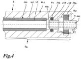
- the structure of the pipeline part 4 corresponds essentially to that of the pipeline parts 4 in the Figures 1 and 3
- the pipe part 4 extends from the outer or distal end 20 of the connecting device 2 to the likewise outer or distal end 30 of the connecting device 3.
- the pipe part 4 extends completely along the media line 1, so that no further conductors or heating conductors are required in the area of the connecting devices 2, 3 for heating them.
- a connector plug 5 with connecting cables 50, 51 is used to electrically connect the two conductors 141, 142 or heating conductors 41, 42 to an electrical power supply.
- An electrical connector can also be used into which a connector plug with connecting cables can be plugged in.
- connecting cables can be used which lead out to the outside of the connecting device or possibly even to a power source.
- the connection plug is plugged onto two connection elements 6, 7 which are connected to the two conductors 141, 142 or heating conductors 41, 42.
- material is exposed on a surface of the pipe part 4 which covers the conductors 141, 142 or heating conductors 41, 42. This is done, for example, by laser cutting.
- the laser beam can burn the material, hitting the pipe part 4 perpendicularly or essentially perpendicular to its outer surface.
- the laser cut can be done by the laser beam blasting off material, hitting the outer surface of the pipe part tangentially.
- the conductors 141, 142 or heating conductors 41, 42 can be connected by soldering or welding, in particular by inductive soldering or pulse welding. After connecting the two connection elements 6, 7 with the conductors 141, 142 or heating conductors 41, 42, the connection elements protrude from the pipe section 4.
- the connection plug 5 is then plugged onto the ends of the two connection elements 6, 7 protruding from the surface of the pipe section 4.
- a sealing ring 32 To seal the connection plug, the Figure 1 shown embodiment, a sealing ring 32.
- a recess 31 receiving the connector plug or the connection elements 6, 7 can be sealed from the outside and thus protection against the ingress of moisture in particular can be provided. This is shown in the Figures 1 and 3 shown.
- connecting cables When connecting cables are led out, they can be sealed to the outside by individual strand seals, in particular by providing very small sealing rings for each connecting cable.
- the two end-side connecting devices 2, 3 are arranged in the two end areas 45, 46 of the pipe part 4. They are formed there as connecting contours by overmolding the end areas 45, 46 of the pipe part 4.
- the two conductors 141, 142 or heating conductors 41, 42 are first exposed, then the two conductors 141, 142 or heating conductors 41, 42 are connected to the two connection elements 6, 7 and then by overmolding the two end areas 45, 46 of the pipe section 4, the respective connection contour 2, 3 is applied.
- the connection plug 5 is then plugged onto the two connection elements 6, 7 or their protruding ends in order to enable a connection to an electrical power supply.
- the connection contours can be designed as a plug, screw or coupling contour, for example.
- connection of the two conductors 141, 142 or heating conductors 41, 42 is carried out according to the embodiment in Figure 1 only in the area of one connecting device 2. In principle, however, it would also be possible, if this is desired, for example with more than two conductors or heating conductors, to also provide a connection of the conductors or heating conductors in the other connecting device 3. Instead of the straight shape of the connecting devices 2, 3 shown, these can also be designed, for example, as Y or T lines, flow-optimized in the radius of the pipe section 4 or as angle plugs.
- a connecting sleeve 140 can also be formed. This is formed by widening the end region 45 or 46.
- the outer layer 44 is provided with a greater wall thickness at least in the end region 46. On the inside of the outer layer 44, this is provided with recesses 144, 145, 146 for inserting a sealing ring 147 and a connection contour 9 on an aggregate or an aggregate plug and a holding device 148 for locking this or this in the connecting sleeve 140.
- the connection contour or the connection plug has a projecting portion 99, which is engaged behind by the holding device 148.
- the holding device can be designed, for example, as a spring-back ring and can, similar to the one in Figure 3
- the axial clip 92 shown may have an inclined or chamfered surface to enable easier insertion of the connector plug or the connection contour.
- connection contour 9 extends very close to the electrically conductive device 100, and can even be arranged concentrically to it by engaging in the corresponding end section of the layer of the pipeline part 4 containing it.
- the individual layers of the pipeline part are not in one plane, but the outer layer 44 extends beyond the inner layer 43 and the middle layer 40.
- a heat-conducting sleeve 111 can be provided for the connection contour 9. It is inserted into the fluid channel 110 of the connection contour 9 and is thus in direct contact with the medium or fluid that flows through the media line 1 and the connection contour 9.
- the heat-conducting sleeve 111 is advantageously made of stainless steel or aluminum.
- the heat-conducting sleeve 111 is tempered by the medium or fluid in the area of the (unheated) connecting sleeve 140. The heat can therefore be better transferred between the heated areas of the pipe part 4 with the connecting sleeve 140 and the connection contour 9 with the pipe part. When these areas are electrically heated, the heat-conducting sleeve 111 at least has a supporting effect due to its thermal conductivity.
- connection contour can also have a different shape.
- the shape can be adapted to the respective application, whereby standard SAE connector shapes can also be selected.
- connection device or contour according to Figure 3 has a recess 31 for inserting the connector plug 5. This is sealed within the molded recess 31 by a sealing element, here a sealing ring 32, such as an O-ring.
- a sealing element here a sealing ring 32, such as an O-ring.
- connection contour is further provided with a receiving groove 33 in the end region 34, which is directed in the direction of a protective or insulating pipe, illustrated by a corrugated pipe 8.
- the receiving groove 33 serves to insert a collar 80 of the corrugated pipe 8 that projects inwards at the end.
- the corrugated pipe 8 or the insulation gap 81 between the corrugated pipe 8 and the pipe part 4 serves to insulate the section of the pipe part 4 arranged between the two connecting devices 2, 3.
- a seal 39 is arranged in the receiving groove 33 to prevent moisture from penetrating into the space between the corrugated pipe 8 and the pipe part 4, i.e. the insulation gap 81.
- an O-ring or a two-component seal can be provided there.
- the two-component seal can be molded directly onto the connection contour. The same basically applies to the sealing ring 32, which seals the connector plug 5 within the recess 31. This can also be molded directly during the manufacture of the connection device.
- connection contour 9 on an aggregate, in particular an aggregate plug for connecting the media line to an aggregate
- the contour of the connecting device 3 in the end region is correspondingly tapered or provided with a smaller diameter than, for example, in the region in which the recess 31 for receiving the connection plug 5 is arranged.
- the connection contour 9 has in the Figure 3 shown embodiment has a connection heating on the unit side, which is illustrated by the indicated heating conductors 90. Furthermore, the connection contour 9 has a projecting front flange 91. This serves to fasten and lock the connection contour 9 to the connecting device 3. An axial clip is used to fix the connection contour 9 in the area of the flange 91. 92.
- This has a circumferential, inward-facing collar 93 which engages in a corresponding receiving groove 35 of the connecting device 3.
- the receiving groove 35 is directly formed during the injection molding of the connecting device 3 and serves to axially hold the axial clip 92 on the connecting device 3.
- a holding contour 94 of the axial clip 92 is used to grip behind the flange 91.
- this has a holding surface 95 which is arranged approximately parallel to the side walls of the collar 93.
- the holding contour 94 has an obliquely running conical or chamfered surface 96.
- the conical section of the axial clip 92 has a larger opening in the outward direction and a smaller opening in the inward direction, i.e. in the direction of the holding surface 95.
- connection contour 9 two seals in the form of sealing rings 38, e.g. O-rings, are attached to the connection part 37 of the connecting device 3.
- O-rings e.g. O-rings
- the pipe part 4 can be designed as an electrically heatable multi-layer plastic pipe as a so-called MLT pipe (Multi Layer Technique).
- MLT pipe Multi Layer Technique
- polyamides can be used for all three layers 40, 43, 44, in particular PA12 or PA11.
- the inner layer 43 as it is in particular Figure 2 can be removed, has, for example, a layer thickness s i of 0.1 to 0.3 mm
- the outer layer 44 as shown in Figure 2 can also be seen, for example a layer thickness s a of 0.4 mm.
- the outer layer 44 can be processed by laser in order to expose the conductors 141, 142 or heating conductors 41, 42 or to attach components of the connecting device using a laser welding process.
- the middle layer 40 can have a layer thickness s m of 0.3 to 1.0 mm.
- a barrier layer can be provided between the middle layer 40 and the inner layer 43, which Figure 2 is not shown. It is also possible to provide a barrier layer between the outer layer 44 and the middle layer 40 in order to protect these in the vicinity of the conductors 141, 142 or heating conductors 41, 42 against damage when they are exposed. In the area of the two conductors or heating conductors, even if a barrier layer is provided, it should generally be possible to remove this in order to enable the conductors or heating conductors 41, 42 to be connected to the connection elements 6, 7. If the barrier layer is provided between the outer and middle layers, the outer layer up to the barrier layer can be removed by laser cutting and then the barrier layer can be removed mechanically in order to be able to make contact with the conductors or heating conductors.
- d 0.4 mm.
- two conductors or heating conductors can be provided. However, it is also possible to provide more, for example four conductors or heating conductors.
- the distance a between the two conductors or heating conductors 41, 42 and the windings of the two conductors or heating conductors can be 20 to 60 mm, in particular 40 mm.
- the pitch S of the two conductors or heating conductors is comparatively large and can be 20 to 150 mm, in particular 40 to 80 mm.
- the total wall thickness b of the pipe part 4 is in particular 4 mm or less, e.g. 2 mm or less, e.g. 1.5 mm or less, e.g. 1.0 mm or less.
- the locations at which the laser cut is to be made are determined by knowing the position of the two conductors or heating conductors on at least one of the front surfaces 47, 48 of the two ends of the pipe section 4 and in particular also their pitch S, so that regardless of the actual positioning of the pipe section 4 in a laser cutting device or a device for producing the media line 1, the correct position for the laser and thus the laser cut can be easily found.
- the position of the conductors or heating conductors is determined. This advantageously makes it possible to automate the production of the media line, i.e. to avoid manual intervention, since the position determination of the connection point and the laser cut can be carried out under computer control.
- the pipe section 4 coming from the extrusion system is placed in a laser cutting device during the production of the media line 1, the two conductors 141, 142 or heating conductors 41, 42 embedded in the wall of the pipe section are exposed by laser cutting and electrically connected to the connection elements 6, 7. Subsequently, a respective plug or coupling contour is sprayed onto both ends of the pipe section 4 in the end regions 45, 46 in a plastic injection device to produce the two connecting devices 2, 3 or is applied in another way by primary molding or material bonding.
- corrugated pipe 8 and connection contour 9 O-rings or other sealing elements can also be subsequently added to the connecting device 2, 3 at the corresponding locations provided for this purpose. It is also possible to mold such sealing elements during the plastic injection process or when producing the connecting device 2, 3.
- the end regions of the pipe part can be provided with connection contours after the electrically conductive device embedded in its wall has been exposed.
Landscapes
- Engineering & Computer Science (AREA)
- General Engineering & Computer Science (AREA)
- Mechanical Engineering (AREA)
- Physics & Mathematics (AREA)
- Electromagnetism (AREA)
- Pipe Accessories (AREA)
- Resistance Heating (AREA)
Applications Claiming Priority (2)
| Application Number | Priority Date | Filing Date | Title |
|---|---|---|---|
| DE102010051550A DE102010051550A1 (de) | 2010-11-18 | 2010-11-18 | Konfektionierte elektrisch beheizbare Medienleitung sowie Verfahren zum Herstellen einer solchen Medienleitung |
| PCT/EP2011/005719 WO2012065710A2 (de) | 2010-11-18 | 2011-11-14 | Konfektionierte elektrisch beheizbare medienleitung sowie verfahren zum herstellen einer solchen medienleitung |
Publications (2)
| Publication Number | Publication Date |
|---|---|
| EP2641006A2 EP2641006A2 (de) | 2013-09-25 |
| EP2641006B1 true EP2641006B1 (de) | 2024-09-25 |
Family
ID=45099007
Family Applications (1)
| Application Number | Title | Priority Date | Filing Date |
|---|---|---|---|
| EP11791433.3A Active EP2641006B1 (de) | 2010-11-18 | 2011-11-14 | Konfektionierte elektrisch beheizbare medienleitung sowie verfahren zum herstellen einer solchen medienleitung |
Country Status (6)
Families Citing this family (22)
| Publication number | Priority date | Publication date | Assignee | Title |
|---|---|---|---|---|
| DE102011018243A1 (de) * | 2011-04-19 | 2012-10-25 | Voss Automotive Gmbh | Mehrlagige elektrisch beheizbare Medienleitung |
| DE102011017811A1 (de) * | 2011-04-29 | 2012-10-31 | Evonik Degussa Gmbh | Temperierbare Rohrleitung für Offshoreanwendungen |
| DE102012020055A1 (de) | 2012-10-12 | 2014-04-17 | Voss Automotive Gmbh | Elektrisch beheizbare Medienleitung sowie Verfahren zum Herstellen einer solchen |
| DE102013223910A1 (de) | 2013-11-22 | 2015-05-28 | Contitech Ag | Flexibler, mehrschichtiger, beheizbarer Schlauch |
| DE102014005093A1 (de) | 2014-01-08 | 2015-07-09 | Voss Automotive Gmbh | Konfektionierte beheizbare Medienleitung sowie Verfahren zu deren Herstellung |
| DE102014005094A1 (de) | 2014-01-08 | 2015-07-09 | Voss Automotive Gmbh | Beheizbare Medienleitung, Verfahren zu deren Herstellung und Schaltungsanordnung für eine beheizbare Medienleitung |
| US10139132B2 (en) | 2015-03-31 | 2018-11-27 | Lam Research Corporation | Apparatus for thermal control of tubing assembly and associated methods |
| EP3130441B1 (de) * | 2015-08-12 | 2017-12-13 | TI Automotive (Fuldabrück) GmbH | Verbinder und verfahren zur herstellung eines verbinders |
| EP3133329B1 (de) * | 2015-08-20 | 2018-10-24 | TI Automotive (Fuldabrück) GmbH | Beheizbare kraftfahrzeugrohrleitung und verfahren zur herstellung einer beheizbaren kraftfahrzeugrohrleitung |
| DE102016002103A1 (de) | 2016-02-24 | 2017-08-24 | Voss Automotive Gmbh | Mehrschichtige beheizbare Medienleitung und konfektionierte Medienleitung mit zumindest einer solchen |
| CN105710541B (zh) * | 2016-04-12 | 2017-11-24 | 燕山大学 | 一种基于大口径焊管脉冲电流加热对接摩擦焊装置 |
| US11033140B2 (en) * | 2016-07-18 | 2021-06-15 | Mavam Espresso | System and method for fluid temperature stability for multi-section beverage making machine |
| US10396500B2 (en) | 2016-08-31 | 2019-08-27 | Norma U.S. Holding Llc | Electrically conductive conduit assembly |
| DE102017131433A1 (de) * | 2017-01-10 | 2018-07-12 | ARTE Reverse Engineering GbR (vertretungsberechtigte Gesellschafter Alexander Reinisch, 98617 Vachdorf; Heiko Lantzsch, 99817 Eisenach) | Umhausung, bildend einen Hohlraum zur Aufnahme von Flüssigkeiten oder festen Körpern |
| US10197203B2 (en) * | 2017-05-17 | 2019-02-05 | Gates Corporation | Heated fluid conduit |
| US20190189472A1 (en) * | 2017-12-18 | 2019-06-20 | Trebor International | Pfa tube heater with flexible heating elements |
| DE202018100115U1 (de) | 2018-01-10 | 2018-02-27 | Voss Automotive Gmbh | Konfektionierte Fluidleitung |
| DE102018000932A1 (de) | 2018-02-06 | 2019-08-08 | Voss Automotive Gmbh | Medienleitung mit Verbindungskontur sowie Verfahren zum Herstellen einer mit zumindest einer Verbindungskontur versehenen Medienleitung |
| US10932326B2 (en) | 2018-05-24 | 2021-02-23 | Goodrich Aerospace Services Private Limited | Flexible heated hose assembly with printed positive temperature co-efficient heater |
| DE102020113124A1 (de) | 2020-05-14 | 2021-11-18 | Eberspächer catem Hermsdorf GmbH & Co. KG | PTC-Heizzelle und Verfahren zu deren Herstellung |
| CN112637980B (zh) * | 2020-12-21 | 2022-04-19 | 天津华能杨柳青热电有限责任公司 | 一种远红外线柔性电加热套 |
| DE102022117668A1 (de) | 2022-07-14 | 2024-01-25 | Eichenauer Heizelemente Gmbh & Co. Kg | Schlauch zum Beheizen eines Fluids und Schlauchanordnung |
Citations (1)
| Publication number | Priority date | Publication date | Assignee | Title |
|---|---|---|---|---|
| DE202005004602U1 (de) * | 2005-03-18 | 2005-07-14 | Eichenauer Heizelemente Gmbh & Co. Kg | Beheizte Flüssigkeitsleitung |
Family Cites Families (33)
| Publication number | Priority date | Publication date | Assignee | Title |
|---|---|---|---|---|
| US1809714A (en) * | 1929-04-01 | 1931-06-09 | Mathews Carl Raymond | Heated water hose for filling stations |
| US2516864A (en) * | 1948-08-24 | 1950-08-01 | Gen Electric | Method of making hose from elastomeric composition |
| US3163707A (en) * | 1962-12-27 | 1964-12-29 | Ralph E Darling | Non-stretch flexible tube with conductors therein |
| US3378673A (en) * | 1965-10-18 | 1968-04-16 | Thomas O. Hopper | Electrically heated hose assembly |
| US3764779A (en) * | 1971-05-24 | 1973-10-09 | Takarazuka Control Cable Co In | Winterized control cable |
| NL7414546A (nl) * | 1973-11-15 | 1975-05-20 | Rhone Poulenc Sa | Soepele verwarmingsbuis en werkwijze voor het vervaardigen ervan. |
| US4553023A (en) * | 1981-11-27 | 1985-11-12 | Nordson Corporation | Thermally insulated electrically heated hose for transmitting hot liquids |
| US5713864A (en) * | 1995-04-11 | 1998-02-03 | Sims Level 1, Inc. | Integral conductive polymer resistance heated tubing |
| US5862303A (en) | 1996-05-17 | 1999-01-19 | Advanced Metal Technologies, Ltd. | Electrically heated pipe with helically wound amorphous alloy heater |
| US5791377A (en) * | 1996-07-08 | 1998-08-11 | Yazaki Corporation | Electrically heated conduit |
| US5971251A (en) * | 1997-10-27 | 1999-10-26 | Lear Automotive Dearborn, Inc. | Method of welding a terminal to a flat flexible cable |
| US7120354B2 (en) * | 2000-03-21 | 2006-10-10 | Fisher & Paykel Healthcare Limited | Gases delivery conduit |
| AU2003244171B2 (en) * | 2002-09-09 | 2007-11-15 | Fisher & Paykel Healthcare Limited | Limb for Breathing Circuit |
| DE10326894B3 (de) * | 2003-06-14 | 2004-09-30 | Rasmussen Gmbh | Heizvorrichtung mit einer elektrischen Wärmequelle zum Erwärmen eines Fluids in einer Fluidleitung eines Kraftfahrzeugs |
| US7266293B1 (en) * | 2004-05-03 | 2007-09-04 | Dundas Robert D | Hose for hot liquids having heating element |
| US20070036528A1 (en) * | 2005-07-29 | 2007-02-15 | William Ferrone | Heated hose electrical cord |
| DE102005037183B3 (de) | 2005-08-06 | 2007-05-10 | Rasmussen Gmbh | Beheizbare Fluidleitung |
| DE102005057780A1 (de) * | 2005-12-02 | 2007-06-06 | Dbk David + Baader Gmbh | Fluidkupplungsanordnung mit elektrischer Steckverbinderanordnung |
| SE529417C2 (sv) * | 2005-12-22 | 2007-08-07 | Volvo Lastvagnar Ab | Ledningsnät för ett fordon |
| US7896712B2 (en) * | 2005-12-22 | 2011-03-01 | Tensolite, Llc | Integral bonding attachment |
| DE102006006211B3 (de) | 2006-02-09 | 2007-09-20 | Rehau Ag + Co | Baugruppe zum Leiten und Temperieren einer Harnstoff-Wasser-Lösung und Verfahren zu deren Herstellung |
| DE102006051413B4 (de) | 2006-10-27 | 2009-01-02 | Norma Germany Gmbh | Elektrisch beheizbare Fluidleitung |
| US7732736B2 (en) * | 2007-03-30 | 2010-06-08 | Illinois Tool Works Inc. | Hot melt adhesive hose assembly with thermal fuse link |
| DE202007009588U1 (de) * | 2007-04-26 | 2008-09-04 | Voss Automotive Gmbh | Leitungsverbinder für Medienleitungen |
| ATE533989T1 (de) | 2007-04-26 | 2011-12-15 | Voss Automotive Gmbh | Leitungsverbinder für medienleitungen |
| DE202007010502U1 (de) | 2007-07-26 | 2008-11-27 | Voss Automotive Gmbh | Konfektionierte Medienleitung |
| US8380056B2 (en) * | 2007-11-01 | 2013-02-19 | Infinity Fluids Corp. | Inter-axial inline fluid heater |
| PL2222995T3 (pl) | 2007-12-21 | 2015-04-30 | Voss Automotive Gmbh | Element połączeniowy przewodów dla przewodów dla mediów oraz zespolony przewód dla mediów z co najmniej jednym takim elementem połączeniowym przewodów |
| DE202007018089U1 (de) * | 2007-12-21 | 2009-05-07 | Voss Automotive Gmbh | Beheizbare Medienleitung |
| US20100175469A1 (en) | 2009-01-09 | 2010-07-15 | Ni Frank Zhi | Electrically heated fluid tube |
| EP2216866A3 (en) * | 2009-02-06 | 2011-07-13 | HID Global GmbH | Method to strip a portion of an insulated wire |
| US8559800B2 (en) * | 2009-02-13 | 2013-10-15 | The Gates Corporation | Heated fluid conduit end covers, systems and methods |
| US20130248501A1 (en) * | 2012-03-21 | 2013-09-26 | Control Laser Corporation | Rotating laser wire stripping system |
-
2010
- 2010-11-18 DE DE102010051550A patent/DE102010051550A1/de not_active Withdrawn
-
2011
- 2011-11-14 JP JP2013539159A patent/JP6000271B2/ja not_active Expired - Fee Related
- 2011-11-14 US US13/885,043 patent/US9644776B2/en not_active Expired - Fee Related
- 2011-11-14 WO PCT/EP2011/005719 patent/WO2012065710A2/de active Application Filing
- 2011-11-14 CN CN201180065267.3A patent/CN103477138B/zh active Active
- 2011-11-14 EP EP11791433.3A patent/EP2641006B1/de active Active
Patent Citations (1)
| Publication number | Priority date | Publication date | Assignee | Title |
|---|---|---|---|---|
| DE202005004602U1 (de) * | 2005-03-18 | 2005-07-14 | Eichenauer Heizelemente Gmbh & Co. Kg | Beheizte Flüssigkeitsleitung |
Also Published As
| Publication number | Publication date |
|---|---|
| JP2014500448A (ja) | 2014-01-09 |
| CN103477138A (zh) | 2013-12-25 |
| EP2641006A2 (de) | 2013-09-25 |
| US9644776B2 (en) | 2017-05-09 |
| JP6000271B2 (ja) | 2016-09-28 |
| WO2012065710A3 (de) | 2012-08-30 |
| WO2012065710A8 (de) | 2012-10-26 |
| CN103477138B (zh) | 2016-10-19 |
| DE102010051550A1 (de) | 2012-05-24 |
| WO2012065710A2 (de) | 2012-05-24 |
| US20130294757A1 (en) | 2013-11-07 |
Similar Documents
| Publication | Publication Date | Title |
|---|---|---|
| EP2641006B1 (de) | Konfektionierte elektrisch beheizbare medienleitung sowie verfahren zum herstellen einer solchen medienleitung | |
| DE102010032189B4 (de) | Verfahren zum Herstellen einer beheizbaren Medienleitung und beheizbare Medienleitung, hergestellt nach dem Verfahren | |
| EP2363627B1 (de) | Leitungsverbinder für Medienleitungen | |
| EP2766651B1 (de) | Konfektionierte medienleitung mit zumindest einer beheizbaren medienleitung und mit zumindest einem zumindest teilweise beheizbaren leitungsverbinder | |
| EP2699414B1 (de) | Mehrlagige elektrisch beheizbare medienleitung | |
| EP2788692B1 (de) | Konfektionierte beheizbare medienleitung mit einer medienleitung mit zumindest zwei auf deren aussenseite angeordneten heizelementen und verfahren zu ihrer herstellung | |
| DE202007010502U1 (de) | Konfektionierte Medienleitung | |
| DE202011106751U1 (de) | Zumindest teilweise beheizbarer Leitungsverbinder für eine beheizbare Medienleitung sowie konfektionierte Medienleitung mit einem solchen Leitungsverbinder | |
| EP1985908A1 (de) | Leitungsverbinder für Medienleitungen | |
| EP2906864B1 (de) | Elektrisch beheizbare medienleitung sowie verfahren zum herstellen einer solchen | |
| DE102008025299A1 (de) | Anschlussvorrichtung für medienführende, elektrisch beheizbare Schläuche | |
| EP2418364B1 (de) | Beheizbare Leitung | |
| EP2788646B2 (de) | Konfektionierte medienleitung und verfahren zum konfektionieren einer medienleitung mit innenliegenden heizelementen | |
| DE102008018658A1 (de) | Beheizbares Leitungselement für ein Fluid | |
| DE102014018372A1 (de) | Konfektionierte beheizbare Medienleitung sowie Verfahren zu deren Herstellung | |
| DE202008007392U1 (de) | Fluidleitung und Leitungsverbinder zum Führen und Beheizen eines Mediums | |
| EP3092433B1 (de) | Konfektionierte beheizbare medienleitung sowie verfahren zu deren herstellung | |
| EP1610049B1 (de) | Schlauchverbindungssystem für einen beheizbaren Schlauch | |
| EP3234434B1 (de) | Beheizbare medienleitung sowie verfahren zum herstellen einer beheizbaren medienleitung | |
| DE102012025014A1 (de) | Beheizbare Medienleitung sowie Verfahren zum Herstellen einer solchen | |
| DE102013011448A1 (de) | Heizleitung für eine beheizbare Fluid-Leitung | |
| DE102011115890A1 (de) | Zumindest teilweise beheizbarer Leitungsverbinder für einebeheizbare Medienleitung sowie konfektionierte Medienleitung mit einem solchen Leitungsverbinder |
Legal Events
| Date | Code | Title | Description |
|---|---|---|---|
| PUAI | Public reference made under article 153(3) epc to a published international application that has entered the european phase |
Free format text: ORIGINAL CODE: 0009012 |
|
| 17P | Request for examination filed |
Effective date: 20130328 |
|
| AK | Designated contracting states |
Kind code of ref document: A2 Designated state(s): AL AT BE BG CH CY CZ DE DK EE ES FI FR GB GR HR HU IE IS IT LI LT LU LV MC MK MT NL NO PL PT RO RS SE SI SK SM TR |
|
| DAX | Request for extension of the european patent (deleted) | ||
| RIN1 | Information on inventor provided before grant (corrected) |
Inventor name: WESTMEIER, JOERG Inventor name: ETSCHEID, TOBIAS Inventor name: GRAMCKOW, ERIK Inventor name: HEIENBROK, MARK Inventor name: SACHSE, MARTIN |
|
| 17Q | First examination report despatched |
Effective date: 20151022 |
|
| STAA | Information on the status of an ep patent application or granted ep patent |
Free format text: STATUS: EXAMINATION IS IN PROGRESS |
|
| STAA | Information on the status of an ep patent application or granted ep patent |
Free format text: STATUS: EXAMINATION IS IN PROGRESS |
|
| GRAP | Despatch of communication of intention to grant a patent |
Free format text: ORIGINAL CODE: EPIDOSNIGR1 |
|
| STAA | Information on the status of an ep patent application or granted ep patent |
Free format text: STATUS: GRANT OF PATENT IS INTENDED |
|
| INTG | Intention to grant announced |
Effective date: 20231208 |
|
| GRAS | Grant fee paid |
Free format text: ORIGINAL CODE: EPIDOSNIGR3 |
|
| GRAJ | Information related to disapproval of communication of intention to grant by the applicant or resumption of examination proceedings by the epo deleted |
Free format text: ORIGINAL CODE: EPIDOSDIGR1 |
|
| GRAL | Information related to payment of fee for publishing/printing deleted |
Free format text: ORIGINAL CODE: EPIDOSDIGR3 |
|
| STAA | Information on the status of an ep patent application or granted ep patent |
Free format text: STATUS: EXAMINATION IS IN PROGRESS |
|
| P01 | Opt-out of the competence of the unified patent court (upc) registered |
Effective date: 20240305 |
|
| GRAP | Despatch of communication of intention to grant a patent |
Free format text: ORIGINAL CODE: EPIDOSNIGR1 |
|
| STAA | Information on the status of an ep patent application or granted ep patent |
Free format text: STATUS: GRANT OF PATENT IS INTENDED |
|
| INTC | Intention to grant announced (deleted) | ||
| GRAS | Grant fee paid |
Free format text: ORIGINAL CODE: EPIDOSNIGR3 |
|
| INTG | Intention to grant announced |
Effective date: 20240430 |
|
| GRAJ | Information related to disapproval of communication of intention to grant by the applicant or resumption of examination proceedings by the epo deleted |
Free format text: ORIGINAL CODE: EPIDOSDIGR1 |
|
| GRAL | Information related to payment of fee for publishing/printing deleted |
Free format text: ORIGINAL CODE: EPIDOSDIGR3 |
|
| STAA | Information on the status of an ep patent application or granted ep patent |
Free format text: STATUS: EXAMINATION IS IN PROGRESS |
|
| GRAP | Despatch of communication of intention to grant a patent |
Free format text: ORIGINAL CODE: EPIDOSNIGR1 |
|
| STAA | Information on the status of an ep patent application or granted ep patent |
Free format text: STATUS: GRANT OF PATENT IS INTENDED |
|
| INTC | Intention to grant announced (deleted) | ||
| INTG | Intention to grant announced |
Effective date: 20240708 |
|
| GRAA | (expected) grant |
Free format text: ORIGINAL CODE: 0009210 |
|
| STAA | Information on the status of an ep patent application or granted ep patent |
Free format text: STATUS: THE PATENT HAS BEEN GRANTED |
|
| AK | Designated contracting states |
Kind code of ref document: B1 Designated state(s): AL AT BE BG CH CY CZ DE DK EE ES FI FR GB GR HR HU IE IS IT LI LT LU LV MC MK MT NL NO PL PT RO RS SE SI SK SM TR |
|
| REG | Reference to a national code |
Ref country code: GB Ref legal event code: FG4D Free format text: NOT ENGLISH |
|
| REG | Reference to a national code |
Ref country code: CH Ref legal event code: EP |
|
| REG | Reference to a national code |
Ref country code: DE Ref legal event code: R096 Ref document number: 502011017482 Country of ref document: DE |
|
| REG | Reference to a national code |
Ref country code: IE Ref legal event code: FG4D Free format text: LANGUAGE OF EP DOCUMENT: GERMAN |
|
| PGFP | Annual fee paid to national office [announced via postgrant information from national office to epo] |
Ref country code: DE Payment date: 20241029 Year of fee payment: 14 |
|
| REG | Reference to a national code |
Ref country code: LT Ref legal event code: MG9D |
|
| PG25 | Lapsed in a contracting state [announced via postgrant information from national office to epo] |
Ref country code: NO Free format text: LAPSE BECAUSE OF FAILURE TO SUBMIT A TRANSLATION OF THE DESCRIPTION OR TO PAY THE FEE WITHIN THE PRESCRIBED TIME-LIMIT Effective date: 20241225 |
|
| PG25 | Lapsed in a contracting state [announced via postgrant information from national office to epo] |
Ref country code: GR Free format text: LAPSE BECAUSE OF FAILURE TO SUBMIT A TRANSLATION OF THE DESCRIPTION OR TO PAY THE FEE WITHIN THE PRESCRIBED TIME-LIMIT Effective date: 20241226 Ref country code: FI Free format text: LAPSE BECAUSE OF FAILURE TO SUBMIT A TRANSLATION OF THE DESCRIPTION OR TO PAY THE FEE WITHIN THE PRESCRIBED TIME-LIMIT Effective date: 20240925 |
|
| PG25 | Lapsed in a contracting state [announced via postgrant information from national office to epo] |
Ref country code: BG Free format text: LAPSE BECAUSE OF FAILURE TO SUBMIT A TRANSLATION OF THE DESCRIPTION OR TO PAY THE FEE WITHIN THE PRESCRIBED TIME-LIMIT Effective date: 20240925 |
|
| PG25 | Lapsed in a contracting state [announced via postgrant information from national office to epo] |
Ref country code: LV Free format text: LAPSE BECAUSE OF FAILURE TO SUBMIT A TRANSLATION OF THE DESCRIPTION OR TO PAY THE FEE WITHIN THE PRESCRIBED TIME-LIMIT Effective date: 20240925 |
|
| PG25 | Lapsed in a contracting state [announced via postgrant information from national office to epo] |
Ref country code: RS Free format text: LAPSE BECAUSE OF FAILURE TO SUBMIT A TRANSLATION OF THE DESCRIPTION OR TO PAY THE FEE WITHIN THE PRESCRIBED TIME-LIMIT Effective date: 20241225 |
|
| REG | Reference to a national code |
Ref country code: NL Ref legal event code: MP Effective date: 20240925 |
|
| PG25 | Lapsed in a contracting state [announced via postgrant information from national office to epo] |
Ref country code: RS Free format text: LAPSE BECAUSE OF FAILURE TO SUBMIT A TRANSLATION OF THE DESCRIPTION OR TO PAY THE FEE WITHIN THE PRESCRIBED TIME-LIMIT Effective date: 20241225 Ref country code: NO Free format text: LAPSE BECAUSE OF FAILURE TO SUBMIT A TRANSLATION OF THE DESCRIPTION OR TO PAY THE FEE WITHIN THE PRESCRIBED TIME-LIMIT Effective date: 20241225 Ref country code: LV Free format text: LAPSE BECAUSE OF FAILURE TO SUBMIT A TRANSLATION OF THE DESCRIPTION OR TO PAY THE FEE WITHIN THE PRESCRIBED TIME-LIMIT Effective date: 20240925 Ref country code: GR Free format text: LAPSE BECAUSE OF FAILURE TO SUBMIT A TRANSLATION OF THE DESCRIPTION OR TO PAY THE FEE WITHIN THE PRESCRIBED TIME-LIMIT Effective date: 20241226 Ref country code: FI Free format text: LAPSE BECAUSE OF FAILURE TO SUBMIT A TRANSLATION OF THE DESCRIPTION OR TO PAY THE FEE WITHIN THE PRESCRIBED TIME-LIMIT Effective date: 20240925 Ref country code: BG Free format text: LAPSE BECAUSE OF FAILURE TO SUBMIT A TRANSLATION OF THE DESCRIPTION OR TO PAY THE FEE WITHIN THE PRESCRIBED TIME-LIMIT Effective date: 20240925 |
|
| PG25 | Lapsed in a contracting state [announced via postgrant information from national office to epo] |
Ref country code: NL Free format text: LAPSE BECAUSE OF FAILURE TO SUBMIT A TRANSLATION OF THE DESCRIPTION OR TO PAY THE FEE WITHIN THE PRESCRIBED TIME-LIMIT Effective date: 20240925 |
|
| PG25 | Lapsed in a contracting state [announced via postgrant information from national office to epo] |
Ref country code: IS Free format text: LAPSE BECAUSE OF FAILURE TO SUBMIT A TRANSLATION OF THE DESCRIPTION OR TO PAY THE FEE WITHIN THE PRESCRIBED TIME-LIMIT Effective date: 20250125 Ref country code: PT Free format text: LAPSE BECAUSE OF FAILURE TO SUBMIT A TRANSLATION OF THE DESCRIPTION OR TO PAY THE FEE WITHIN THE PRESCRIBED TIME-LIMIT Effective date: 20250127 |
|
| PG25 | Lapsed in a contracting state [announced via postgrant information from national office to epo] |
Ref country code: RO Free format text: LAPSE BECAUSE OF FAILURE TO SUBMIT A TRANSLATION OF THE DESCRIPTION OR TO PAY THE FEE WITHIN THE PRESCRIBED TIME-LIMIT Effective date: 20240925 Ref country code: SM Free format text: LAPSE BECAUSE OF FAILURE TO SUBMIT A TRANSLATION OF THE DESCRIPTION OR TO PAY THE FEE WITHIN THE PRESCRIBED TIME-LIMIT Effective date: 20240925 |
|
| PG25 | Lapsed in a contracting state [announced via postgrant information from national office to epo] |
Ref country code: ES Free format text: LAPSE BECAUSE OF FAILURE TO SUBMIT A TRANSLATION OF THE DESCRIPTION OR TO PAY THE FEE WITHIN THE PRESCRIBED TIME-LIMIT Effective date: 20240925 |
|
| PG25 | Lapsed in a contracting state [announced via postgrant information from national office to epo] |
Ref country code: EE Free format text: LAPSE BECAUSE OF FAILURE TO SUBMIT A TRANSLATION OF THE DESCRIPTION OR TO PAY THE FEE WITHIN THE PRESCRIBED TIME-LIMIT Effective date: 20240925 |
|
| PG25 | Lapsed in a contracting state [announced via postgrant information from national office to epo] |
Ref country code: PL Free format text: LAPSE BECAUSE OF FAILURE TO SUBMIT A TRANSLATION OF THE DESCRIPTION OR TO PAY THE FEE WITHIN THE PRESCRIBED TIME-LIMIT Effective date: 20240925 Ref country code: CZ Free format text: LAPSE BECAUSE OF FAILURE TO SUBMIT A TRANSLATION OF THE DESCRIPTION OR TO PAY THE FEE WITHIN THE PRESCRIBED TIME-LIMIT Effective date: 20240925 |
|
| PG25 | Lapsed in a contracting state [announced via postgrant information from national office to epo] |
Ref country code: IT Free format text: LAPSE BECAUSE OF FAILURE TO SUBMIT A TRANSLATION OF THE DESCRIPTION OR TO PAY THE FEE WITHIN THE PRESCRIBED TIME-LIMIT Effective date: 20240925 Ref country code: SK Free format text: LAPSE BECAUSE OF FAILURE TO SUBMIT A TRANSLATION OF THE DESCRIPTION OR TO PAY THE FEE WITHIN THE PRESCRIBED TIME-LIMIT Effective date: 20240925 |
|
| REG | Reference to a national code |
Ref country code: DE Ref legal event code: R097 Ref document number: 502011017482 Country of ref document: DE |
|
| REG | Reference to a national code |
Ref country code: CH Ref legal event code: PL |
|
| PG25 | Lapsed in a contracting state [announced via postgrant information from national office to epo] |
Ref country code: MC Free format text: LAPSE BECAUSE OF FAILURE TO SUBMIT A TRANSLATION OF THE DESCRIPTION OR TO PAY THE FEE WITHIN THE PRESCRIBED TIME-LIMIT Effective date: 20240925 |
|
| PG25 | Lapsed in a contracting state [announced via postgrant information from national office to epo] |
Ref country code: DK Free format text: LAPSE BECAUSE OF FAILURE TO SUBMIT A TRANSLATION OF THE DESCRIPTION OR TO PAY THE FEE WITHIN THE PRESCRIBED TIME-LIMIT Effective date: 20240925 |
|
| PG25 | Lapsed in a contracting state [announced via postgrant information from national office to epo] |
Ref country code: LU Free format text: LAPSE BECAUSE OF NON-PAYMENT OF DUE FEES Effective date: 20241114 |
|
| REG | Reference to a national code |
Ref country code: CH Ref legal event code: PL |
|
| PG25 | Lapsed in a contracting state [announced via postgrant information from national office to epo] |
Ref country code: CH Free format text: LAPSE BECAUSE OF NON-PAYMENT OF DUE FEES Effective date: 20241130 |
|
| PLBE | No opposition filed within time limit |
Free format text: ORIGINAL CODE: 0009261 |
|
| STAA | Information on the status of an ep patent application or granted ep patent |
Free format text: STATUS: NO OPPOSITION FILED WITHIN TIME LIMIT |
|
| GBPC | Gb: european patent ceased through non-payment of renewal fee |
Effective date: 20241225 |
|
| 26N | No opposition filed |
Effective date: 20250626 |