EP2640306B1 - Dental implant system and method for producing a dental implant system - Google Patents
Dental implant system and method for producing a dental implant system Download PDFInfo
- Publication number
- EP2640306B1 EP2640306B1 EP11807636.3A EP11807636A EP2640306B1 EP 2640306 B1 EP2640306 B1 EP 2640306B1 EP 11807636 A EP11807636 A EP 11807636A EP 2640306 B1 EP2640306 B1 EP 2640306B1
- Authority
- EP
- European Patent Office
- Prior art keywords
- coating
- connecting stud
- dental implant
- implant system
- region
- Prior art date
- Legal status (The legal status is an assumption and is not a legal conclusion. Google has not performed a legal analysis and makes no representation as to the accuracy of the status listed.)
- Active
Links
- 239000004053 dental implant Substances 0.000 title claims description 47
- 238000004519 manufacturing process Methods 0.000 title claims description 13
- 239000007943 implant Substances 0.000 claims description 80
- 238000000576 coating method Methods 0.000 claims description 70
- 239000011248 coating agent Substances 0.000 claims description 67
- 239000000463 material Substances 0.000 claims description 58
- 239000000919 ceramic Substances 0.000 claims description 37
- 238000000034 method Methods 0.000 claims description 12
- 238000005530 etching Methods 0.000 claims description 10
- 230000008569 process Effects 0.000 claims description 8
- RVTZCBVAJQQJTK-UHFFFAOYSA-N oxygen(2-);zirconium(4+) Chemical compound [O-2].[O-2].[Zr+4] RVTZCBVAJQQJTK-UHFFFAOYSA-N 0.000 claims description 7
- 239000011148 porous material Substances 0.000 claims description 7
- 229910001928 zirconium oxide Inorganic materials 0.000 claims description 7
- PNEYBMLMFCGWSK-UHFFFAOYSA-N Alumina Chemical compound [O-2].[O-2].[O-2].[Al+3].[Al+3] PNEYBMLMFCGWSK-UHFFFAOYSA-N 0.000 claims description 6
- 239000006185 dispersion Substances 0.000 claims description 4
- 239000002086 nanomaterial Substances 0.000 claims description 4
- SIWVEOZUMHYXCS-UHFFFAOYSA-N oxo(oxoyttriooxy)yttrium Chemical compound O=[Y]O[Y]=O SIWVEOZUMHYXCS-UHFFFAOYSA-N 0.000 claims description 4
- 238000010521 absorption reaction Methods 0.000 claims description 2
- XLYOFNOQVPJJNP-UHFFFAOYSA-N water Substances O XLYOFNOQVPJJNP-UHFFFAOYSA-N 0.000 claims description 2
- 229920002994 synthetic fiber Polymers 0.000 claims 3
- XAGFODPZIPBFFR-UHFFFAOYSA-N aluminium Chemical compound [Al] XAGFODPZIPBFFR-UHFFFAOYSA-N 0.000 claims 1
- 229910052782 aluminium Inorganic materials 0.000 claims 1
- 239000004411 aluminium Substances 0.000 claims 1
- 238000007373 indentation Methods 0.000 claims 1
- 125000006850 spacer group Chemical group 0.000 description 38
- 235000019589 hardness Nutrition 0.000 description 19
- 229910052751 metal Inorganic materials 0.000 description 12
- 239000002184 metal Substances 0.000 description 12
- 230000015572 biosynthetic process Effects 0.000 description 11
- 239000004033 plastic Substances 0.000 description 10
- 230000005540 biological transmission Effects 0.000 description 8
- 238000007788 roughening Methods 0.000 description 8
- 239000004696 Poly ether ether ketone Substances 0.000 description 7
- 239000002253 acid Substances 0.000 description 7
- 239000000853 adhesive Substances 0.000 description 7
- 230000001070 adhesive effect Effects 0.000 description 7
- 230000001055 chewing effect Effects 0.000 description 7
- 238000013461 design Methods 0.000 description 7
- 229920002530 polyetherether ketone Polymers 0.000 description 7
- 238000011282 treatment Methods 0.000 description 7
- RTAQQCXQSZGOHL-UHFFFAOYSA-N Titanium Chemical compound [Ti] RTAQQCXQSZGOHL-UHFFFAOYSA-N 0.000 description 6
- 229910010293 ceramic material Inorganic materials 0.000 description 6
- 229910052719 titanium Inorganic materials 0.000 description 6
- 239000010936 titanium Substances 0.000 description 6
- 230000008901 benefit Effects 0.000 description 5
- JUPQTSLXMOCDHR-UHFFFAOYSA-N benzene-1,4-diol;bis(4-fluorophenyl)methanone Chemical compound OC1=CC=C(O)C=C1.C1=CC(F)=CC=C1C(=O)C1=CC=C(F)C=C1 JUPQTSLXMOCDHR-UHFFFAOYSA-N 0.000 description 5
- 230000000694 effects Effects 0.000 description 5
- 230000002349 favourable effect Effects 0.000 description 5
- 230000007774 longterm Effects 0.000 description 5
- IJGRMHOSHXDMSA-UHFFFAOYSA-N Atomic nitrogen Chemical compound N#N IJGRMHOSHXDMSA-UHFFFAOYSA-N 0.000 description 4
- 238000005299 abrasion Methods 0.000 description 4
- 238000010276 construction Methods 0.000 description 4
- 238000001035 drying Methods 0.000 description 4
- 150000002500 ions Chemical class 0.000 description 4
- TWNQGVIAIRXVLR-UHFFFAOYSA-N oxo(oxoalumanyloxy)alumane Chemical compound O=[Al]O[Al]=O TWNQGVIAIRXVLR-UHFFFAOYSA-N 0.000 description 4
- 239000002245 particle Substances 0.000 description 4
- 238000010079 rubber tapping Methods 0.000 description 4
- 239000000470 constituent Substances 0.000 description 3
- 238000003780 insertion Methods 0.000 description 3
- 230000037431 insertion Effects 0.000 description 3
- 238000002360 preparation method Methods 0.000 description 3
- 230000001954 sterilising effect Effects 0.000 description 3
- 238000004659 sterilization and disinfection Methods 0.000 description 3
- 239000000126 substance Substances 0.000 description 3
- 230000003746 surface roughness Effects 0.000 description 3
- 230000008961 swelling Effects 0.000 description 3
- VYPSYNLAJGMNEJ-UHFFFAOYSA-N Silicium dioxide Chemical compound O=[Si]=O VYPSYNLAJGMNEJ-UHFFFAOYSA-N 0.000 description 2
- MCMNRKCIXSYSNV-UHFFFAOYSA-N Zirconium dioxide Chemical compound O=[Zr]=O MCMNRKCIXSYSNV-UHFFFAOYSA-N 0.000 description 2
- 230000002009 allergenic effect Effects 0.000 description 2
- 230000008859 change Effects 0.000 description 2
- 239000000460 chlorine Substances 0.000 description 2
- 238000002845 discoloration Methods 0.000 description 2
- 238000004090 dissolution Methods 0.000 description 2
- 229910000449 hafnium oxide Inorganic materials 0.000 description 2
- WIHZLLGSGQNAGK-UHFFFAOYSA-N hafnium(4+);oxygen(2-) Chemical compound [O-2].[O-2].[Hf+4] WIHZLLGSGQNAGK-UHFFFAOYSA-N 0.000 description 2
- 239000007769 metal material Substances 0.000 description 2
- 229910044991 metal oxide Inorganic materials 0.000 description 2
- 150000004706 metal oxides Chemical class 0.000 description 2
- 229910052757 nitrogen Inorganic materials 0.000 description 2
- 230000000737 periodic effect Effects 0.000 description 2
- 235000019592 roughness Nutrition 0.000 description 2
- 238000005488 sandblasting Methods 0.000 description 2
- 229910002076 stabilized zirconia Inorganic materials 0.000 description 2
- 238000002560 therapeutic procedure Methods 0.000 description 2
- 229920001169 thermoplastic Polymers 0.000 description 2
- 239000004416 thermosoftening plastic Substances 0.000 description 2
- 229910052727 yttrium Inorganic materials 0.000 description 2
- VWQVUPCCIRVNHF-UHFFFAOYSA-N yttrium atom Chemical compound [Y] VWQVUPCCIRVNHF-UHFFFAOYSA-N 0.000 description 2
- 241000894006 Bacteria Species 0.000 description 1
- OKTJSMMVPCPJKN-UHFFFAOYSA-N Carbon Chemical compound [C] OKTJSMMVPCPJKN-UHFFFAOYSA-N 0.000 description 1
- ZAMOUSCENKQFHK-UHFFFAOYSA-N Chlorine atom Chemical compound [Cl] ZAMOUSCENKQFHK-UHFFFAOYSA-N 0.000 description 1
- PXGOKWXKJXAPGV-UHFFFAOYSA-N Fluorine Chemical compound FF PXGOKWXKJXAPGV-UHFFFAOYSA-N 0.000 description 1
- 206010020751 Hypersensitivity Diseases 0.000 description 1
- 206010061218 Inflammation Diseases 0.000 description 1
- OAICVXFJPJFONN-UHFFFAOYSA-N Phosphorus Chemical compound [P] OAICVXFJPJFONN-UHFFFAOYSA-N 0.000 description 1
- NINIDFKCEFEMDL-UHFFFAOYSA-N Sulfur Chemical compound [S] NINIDFKCEFEMDL-UHFFFAOYSA-N 0.000 description 1
- 229910001069 Ti alloy Inorganic materials 0.000 description 1
- QCWXUUIWCKQGHC-UHFFFAOYSA-N Zirconium Chemical compound [Zr] QCWXUUIWCKQGHC-UHFFFAOYSA-N 0.000 description 1
- 238000004026 adhesive bonding Methods 0.000 description 1
- 230000007815 allergy Effects 0.000 description 1
- 229910045601 alloy Inorganic materials 0.000 description 1
- 239000000956 alloy Substances 0.000 description 1
- 238000005275 alloying Methods 0.000 description 1
- 229910002087 alumina-stabilized zirconia Inorganic materials 0.000 description 1
- QVGXLLKOCUKJST-UHFFFAOYSA-N atomic oxygen Chemical compound [O] QVGXLLKOCUKJST-UHFFFAOYSA-N 0.000 description 1
- 230000001580 bacterial effect Effects 0.000 description 1
- 229910052799 carbon Inorganic materials 0.000 description 1
- 229910052729 chemical element Inorganic materials 0.000 description 1
- 229910052801 chlorine Inorganic materials 0.000 description 1
- 239000000356 contaminant Substances 0.000 description 1
- 238000011109 contamination Methods 0.000 description 1
- RKTYLMNFRDHKIL-UHFFFAOYSA-N copper;5,10,15,20-tetraphenylporphyrin-22,24-diide Chemical compound [Cu+2].C1=CC(C(=C2C=CC([N-]2)=C(C=2C=CC=CC=2)C=2C=CC(N=2)=C(C=2C=CC=CC=2)C2=CC=C3[N-]2)C=2C=CC=CC=2)=NC1=C3C1=CC=CC=C1 RKTYLMNFRDHKIL-UHFFFAOYSA-N 0.000 description 1
- 238000005336 cracking Methods 0.000 description 1
- 238000013016 damping Methods 0.000 description 1
- 230000001419 dependent effect Effects 0.000 description 1
- 238000011161 development Methods 0.000 description 1
- 238000000635 electron micrograph Methods 0.000 description 1
- 239000004744 fabric Substances 0.000 description 1
- 229910052731 fluorine Inorganic materials 0.000 description 1
- 239000011737 fluorine Substances 0.000 description 1
- PCHJSUWPFVWCPO-UHFFFAOYSA-N gold Chemical compound [Au] PCHJSUWPFVWCPO-UHFFFAOYSA-N 0.000 description 1
- 239000010931 gold Substances 0.000 description 1
- 229910052737 gold Inorganic materials 0.000 description 1
- 230000035876 healing Effects 0.000 description 1
- 238000010438 heat treatment Methods 0.000 description 1
- 238000000265 homogenisation Methods 0.000 description 1
- 229910052739 hydrogen Inorganic materials 0.000 description 1
- 239000001257 hydrogen Substances 0.000 description 1
- 125000004435 hydrogen atom Chemical class [H]* 0.000 description 1
- 230000004054 inflammatory process Effects 0.000 description 1
- 238000013532 laser treatment Methods 0.000 description 1
- 239000007788 liquid Substances 0.000 description 1
- 230000007246 mechanism Effects 0.000 description 1
- 238000002844 melting Methods 0.000 description 1
- 230000008018 melting Effects 0.000 description 1
- 229910021645 metal ion Inorganic materials 0.000 description 1
- 239000000203 mixture Substances 0.000 description 1
- 229910052760 oxygen Inorganic materials 0.000 description 1
- 239000001301 oxygen Substances 0.000 description 1
- 230000035515 penetration Effects 0.000 description 1
- 229910052698 phosphorus Inorganic materials 0.000 description 1
- 239000011574 phosphorus Substances 0.000 description 1
- 229920001643 poly(ether ketone) Polymers 0.000 description 1
- 239000000843 powder Substances 0.000 description 1
- 239000002244 precipitate Substances 0.000 description 1
- 238000003825 pressing Methods 0.000 description 1
- 239000002994 raw material Substances 0.000 description 1
- 239000000376 reactant Substances 0.000 description 1
- 230000004044 response Effects 0.000 description 1
- 150000003839 salts Chemical class 0.000 description 1
- 238000007789 sealing Methods 0.000 description 1
- 229910052710 silicon Inorganic materials 0.000 description 1
- 239000010703 silicon Substances 0.000 description 1
- 239000000377 silicon dioxide Substances 0.000 description 1
- 238000005245 sintering Methods 0.000 description 1
- 239000007787 solid Substances 0.000 description 1
- 239000002904 solvent Substances 0.000 description 1
- 229910052717 sulfur Inorganic materials 0.000 description 1
- 239000011593 sulfur Substances 0.000 description 1
- 238000004381 surface treatment Methods 0.000 description 1
- 238000012360 testing method Methods 0.000 description 1
- 230000001225 therapeutic effect Effects 0.000 description 1
- 210000001519 tissue Anatomy 0.000 description 1
- 238000012546 transfer Methods 0.000 description 1
- WFKWXMTUELFFGS-UHFFFAOYSA-N tungsten Chemical compound [W] WFKWXMTUELFFGS-UHFFFAOYSA-N 0.000 description 1
- 229910052721 tungsten Inorganic materials 0.000 description 1
- 239000010937 tungsten Substances 0.000 description 1
- 239000011800 void material Substances 0.000 description 1
- 238000009736 wetting Methods 0.000 description 1
- RUDFQVOCFDJEEF-UHFFFAOYSA-N yttrium(III) oxide Inorganic materials [O-2].[O-2].[O-2].[Y+3].[Y+3] RUDFQVOCFDJEEF-UHFFFAOYSA-N 0.000 description 1
- 229910052726 zirconium Inorganic materials 0.000 description 1
Images


Classifications
-
- A—HUMAN NECESSITIES
- A61—MEDICAL OR VETERINARY SCIENCE; HYGIENE
- A61C—DENTISTRY; APPARATUS OR METHODS FOR ORAL OR DENTAL HYGIENE
- A61C8/00—Means to be fixed to the jaw-bone for consolidating natural teeth or for fixing dental prostheses thereon; Dental implants; Implanting tools
- A61C8/0012—Means to be fixed to the jaw-bone for consolidating natural teeth or for fixing dental prostheses thereon; Dental implants; Implanting tools characterised by the material or composition, e.g. ceramics, surface layer, metal alloy
- A61C8/0013—Means to be fixed to the jaw-bone for consolidating natural teeth or for fixing dental prostheses thereon; Dental implants; Implanting tools characterised by the material or composition, e.g. ceramics, surface layer, metal alloy with a surface layer, coating
-
- A—HUMAN NECESSITIES
- A61—MEDICAL OR VETERINARY SCIENCE; HYGIENE
- A61C—DENTISTRY; APPARATUS OR METHODS FOR ORAL OR DENTAL HYGIENE
- A61C8/00—Means to be fixed to the jaw-bone for consolidating natural teeth or for fixing dental prostheses thereon; Dental implants; Implanting tools
- A61C8/0012—Means to be fixed to the jaw-bone for consolidating natural teeth or for fixing dental prostheses thereon; Dental implants; Implanting tools characterised by the material or composition, e.g. ceramics, surface layer, metal alloy
-
- A—HUMAN NECESSITIES
- A61—MEDICAL OR VETERINARY SCIENCE; HYGIENE
- A61C—DENTISTRY; APPARATUS OR METHODS FOR ORAL OR DENTAL HYGIENE
- A61C13/00—Dental prostheses; Making same
- A61C13/0003—Making bridge-work, inlays, implants or the like
- A61C13/0006—Production methods
- A61C13/0007—Production methods using sand blasting
-
- A—HUMAN NECESSITIES
- A61—MEDICAL OR VETERINARY SCIENCE; HYGIENE
- A61C—DENTISTRY; APPARATUS OR METHODS FOR ORAL OR DENTAL HYGIENE
- A61C13/00—Dental prostheses; Making same
- A61C13/0003—Making bridge-work, inlays, implants or the like
- A61C13/0006—Production methods
- A61C13/0018—Production methods using laser
-
- A—HUMAN NECESSITIES
- A61—MEDICAL OR VETERINARY SCIENCE; HYGIENE
- A61C—DENTISTRY; APPARATUS OR METHODS FOR ORAL OR DENTAL HYGIENE
- A61C8/00—Means to be fixed to the jaw-bone for consolidating natural teeth or for fixing dental prostheses thereon; Dental implants; Implanting tools
- A61C8/0048—Connecting the upper structure to the implant, e.g. bridging bars
- A61C8/005—Connecting devices for joining an upper structure with an implant member, e.g. spacers
- A61C8/006—Connecting devices for joining an upper structure with an implant member, e.g. spacers with polygonal positional means, e.g. hexagonal or octagonal
-
- A—HUMAN NECESSITIES
- A61—MEDICAL OR VETERINARY SCIENCE; HYGIENE
- A61C—DENTISTRY; APPARATUS OR METHODS FOR ORAL OR DENTAL HYGIENE
- A61C8/00—Means to be fixed to the jaw-bone for consolidating natural teeth or for fixing dental prostheses thereon; Dental implants; Implanting tools
- A61C8/0048—Connecting the upper structure to the implant, e.g. bridging bars
- A61C8/005—Connecting devices for joining an upper structure with an implant member, e.g. spacers
- A61C8/0068—Connecting devices for joining an upper structure with an implant member, e.g. spacers with an additional screw
-
- A—HUMAN NECESSITIES
- A61—MEDICAL OR VETERINARY SCIENCE; HYGIENE
- A61C—DENTISTRY; APPARATUS OR METHODS FOR ORAL OR DENTAL HYGIENE
- A61C8/00—Means to be fixed to the jaw-bone for consolidating natural teeth or for fixing dental prostheses thereon; Dental implants; Implanting tools
- A61C8/0048—Connecting the upper structure to the implant, e.g. bridging bars
- A61C8/005—Connecting devices for joining an upper structure with an implant member, e.g. spacers
- A61C8/0069—Connecting devices for joining an upper structure with an implant member, e.g. spacers tapered or conical connection
-
- A—HUMAN NECESSITIES
- A61—MEDICAL OR VETERINARY SCIENCE; HYGIENE
- A61C—DENTISTRY; APPARATUS OR METHODS FOR ORAL OR DENTAL HYGIENE
- A61C8/00—Means to be fixed to the jaw-bone for consolidating natural teeth or for fixing dental prostheses thereon; Dental implants; Implanting tools
- A61C8/0018—Means to be fixed to the jaw-bone for consolidating natural teeth or for fixing dental prostheses thereon; Dental implants; Implanting tools characterised by the shape
- A61C8/0022—Self-screwing
-
- A—HUMAN NECESSITIES
- A61—MEDICAL OR VETERINARY SCIENCE; HYGIENE
- A61C—DENTISTRY; APPARATUS OR METHODS FOR ORAL OR DENTAL HYGIENE
- A61C8/00—Means to be fixed to the jaw-bone for consolidating natural teeth or for fixing dental prostheses thereon; Dental implants; Implanting tools
- A61C8/0086—Means to be fixed to the jaw-bone for consolidating natural teeth or for fixing dental prostheses thereon; Dental implants; Implanting tools with shock absorbing means
-
- Y—GENERAL TAGGING OF NEW TECHNOLOGICAL DEVELOPMENTS; GENERAL TAGGING OF CROSS-SECTIONAL TECHNOLOGIES SPANNING OVER SEVERAL SECTIONS OF THE IPC; TECHNICAL SUBJECTS COVERED BY FORMER USPC CROSS-REFERENCE ART COLLECTIONS [XRACs] AND DIGESTS
- Y10—TECHNICAL SUBJECTS COVERED BY FORMER USPC
- Y10T—TECHNICAL SUBJECTS COVERED BY FORMER US CLASSIFICATION
- Y10T29/00—Metal working
- Y10T29/49—Method of mechanical manufacture
- Y10T29/49567—Dental appliance making
Landscapes
- Health & Medical Sciences (AREA)
- General Health & Medical Sciences (AREA)
- Veterinary Medicine (AREA)
- Oral & Maxillofacial Surgery (AREA)
- Public Health (AREA)
- Dentistry (AREA)
- Epidemiology (AREA)
- Life Sciences & Earth Sciences (AREA)
- Animal Behavior & Ethology (AREA)
- Orthopedic Medicine & Surgery (AREA)
- Engineering & Computer Science (AREA)
- Manufacturing & Machinery (AREA)
- Ceramic Engineering (AREA)
- Physics & Mathematics (AREA)
- Optics & Photonics (AREA)
- Dental Prosthetics (AREA)
Description
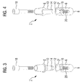
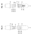
Die Erfindung betrifft ein Dental-Implantatsystem mit einem zur Einbringung in einen Kieferknochen vorgesehenen ersten Implantat-Teil und mit einem diesem zugeordneten, zur Anbringung eines Zahnersatzstücks vorgesehenen zweiten Implantat-Teil, wobei die Implantat-Teile über einen an eines der Implantat-Teile angeformten, in einen im anderen Implantat-Teil vorgesehenen Aufnahmekanal einschiebbaren Verbindungszapfen mechanisch miteinander verbindbar sind.The invention relates to a dental implant system having a first implant part intended for insertion into a jawbone and having a second implant part assigned thereto for attachment of a tooth replacement piece, wherein the implant parts are integrally formed on one of the implant parts. can be mechanically connected to one another in a receiving channel provided in the other implant portion receiving connector.
Zum Ausgleich des Verlusts eines Zahnes können im Rahmen der rekonstruktiven Therapie Dentalimplantate zum Einsatz kommen. Sie werden üblicherweise anstelle eines extrahierten oder ausgefallenen Zahnes in den Kieferknochen eingesetzt, um dort nach einer Einheilphase von etwas vier bis zwölf Wochen ein als Zahnersatz dienendes prothetisches Teil oder eine Krone zu halten. Dazu ist ein derartiges Dentalimplantat üblicherweise als geeignet geformter Metallkörper ausgebildet, der durch Einschrauben an der vorgesehenen Stelle in den Kieferknochen eingesetzt wird. Das Dentalimplantat weist dabei in der Regel am apikalen Ende ein zumeist selbstschneidendes Schraubengewinde auf, mit welchem das Dentalimplantat in das entsprechend präparierte Implantatbett eingesetzt wird.To compensate for the loss of a tooth, dental implants can be used as part of the reconstructive therapy. They are usually used instead of an extracted or failed tooth in the jaw bone to hold there after a healing period of about four to twelve weeks serving as a denture prosthetic part or a crown. For this purpose, such a dental implant is usually formed as a suitably shaped metal body, which is inserted by screwing at the intended location in the jawbone. The dental implant usually has at the apical end a mostly self-tapping screw thread with which the dental implant is inserted into the correspondingly prepared implant bed.
Um eine erleichterte Einbringung in den Patientenmund und insbesondere eine besonders weitgehende Vorbereitung der eigentlichen Prothese bei der Anbringung an das Implantat bereits im Vorfeld der Patientenbehandlung, beispielsweise in einem zahntechnischen Labor, zu ermöglichen, können Dental-Implantatsysteme mehrteilig ausgeführt sein. Insbesondere kann dabei ein grundsätzlich zweiteiliger Aufbau vorgesehen sein, wobei das Dental-Implantatsystem ein erstes, zur Einbringung in den Kieferknochen vorgesehenes, auch als eigentliches Implantat oder Pfostenteil bezeichnetes Implantat-Teil und zusätzlich zu diesem ein zugeordnetes zweites, auch als Aufbauteil bezeichnetes zweites Implantat-Teil umfasst, an das wiederum das als Prothese oder dergleichen vorgesehene Zahnersatzstück anbringbar ist. Das erste Implantat-Teil oder Pfostenteil ist an seiner Außenseite üblicherweise mit einem Gewinde versehen, welches als selbstschneidendes oder auch als nicht selbstschneidendes Gewinde ausgeführt sein kann. Das Pfostenteil wird üblicherweise in einem entsprechend aufbereiteten Implantat-bett des Kieferknochens verankert. Die Konstruktion des im Außenbereich des Dentalimplantats vorgesehenen Gewindes ist dabei üblicherweise für eine hohe Primärstabilität der Anordnung und eine gleichmäßige Weiterleitung der bei der Kaubelastung des Dentalimplantats auftretenden Kräfte in den Kieferknochen ausgelegt.In order to facilitate an easier introduction into the patient's mouth and in particular a particularly extensive preparation of the actual prosthesis when attached to the implant already in advance of the patient treatment, for example in a dental laboratory, dental implant systems can be designed in several parts. In particular, a basically two-part construction can be provided, the dental implant system being a first implant part, also designated as an actual implant or post part, for insertion into the jawbone and, in addition to this, an associated second, also referred to as abutment part second implant part comprises, to which in turn provided as a prosthesis or the like tooth replacement piece can be attached. The first implant part or post part is usually provided on its outer side with a thread, which can be designed as a self-tapping or not as a self-tapping thread. The post part is usually anchored in a correspondingly prepared implant bed of the jawbone. The design of the provided in the outer region of the dental implant thread is usually designed for a high primary stability of the arrangement and a uniform transmission of the forces occurring in the chewing load of the dental implant forces in the jawbone.
Zur mechanischen Verbindung der Implantat-Teile miteinander ist üblicherweise ein an eines der Implantat-Teile, in der Regel an das Aufbauteil, angeformter Verbindungszapfen vorgesehen. Dieser ist in einen im anderen Implantat-Teil, in der Regel im Pfostenteil, vorgesehenen Aufnahmekanal einschiebbar. Hinsichtlich Geometriewahl und Dimensionierung, insbesondere der Querschnitte, sind der Verbindungszapfen einerseits und der Aufnahmekanal andererseits dabei üblicherweise derart aneinander angepasst, dass bei vergleichsweise einfacher Montierbarkeit dennoch eine gute Führung der Bauteile ineinander und damit eine ausreichend hohe mechanische Stabilität erreichbar sind. Das Aufbauteil, das üblicherweise an seinem oberen Bereich mit einer Krone, einer anderen prothetischen Versorgung oder dergleichen in an sich bekannter Weise ausgestattet wird, kann dabei zur mechanischen Verbindung mit dem Pfostenteil über den in den Aufnahmekanal eingeschobenen Verbindungszapfen mit dem Pfostenteil verklebt sein. Das Aufbauteil kann aber auch in das Pfostenteil eingepresst werden und lediglich über eine Verklemmung fixiert werden, oder auch zusätzlich durch eine Zementierung oder Verklebung fixiert werden.For the mechanical connection of the implant parts with one another, a connection pin, which is integrally formed on one of the implant parts, as a rule on the abutment part, is usually provided. This can be inserted into a receiving channel provided in the other implant part, as a rule in the post part. With regard to choice of geometry and dimensioning, in particular of the cross sections, the connecting pin on the one hand and the receiving channel on the other hand are usually adapted to each other so that with a relatively simple mountability still good guidance of the components into one another and thus a sufficiently high mechanical stability can be achieved. The body part, which is usually equipped at its upper portion with a crown, another prosthetic restoration or the like in a conventional manner, can be glued to the mechanical connection with the post part via the inserted into the receiving channel connecting pin with the post part. However, the body part can also be pressed into the post part and fixed only by jamming, or else additionally fixed by cementing or gluing.
Allerdings wird bei derartigen Implantatsystemen das Dentalimplantat beim Einschrauben des Aufbauteils und insbesondere auch später bei Kauvorgängen mechanisch extrem stark belastet, so dass eine Klebeverbindung der genannten Art möglicherweise gerade im Hinblick auf die angestrebte sehr lange Verweildauer im Patientenmund keine ausreichend hohe mechanische Stabilität aufweist. Um dem Rechnung zu tragen, kann das Aufbauteil alternativ auch über eine geeignet gewählte Verbindungsschraube mit dem Pfostenteil verschraubt sein. Bei der Einbringung wird dabei üblicherweise das Gewinde der Verbindungsschraube in ein zugeordnetes Innengewinde im Pfostenteil eingeschraubt. Der Schraubenkopf der Verbindungsschraube presst dabei beim Einschrauben über eine Stirnsenkung des Aufbauteils dieses auf das Dentalimplantat. Derartige mehrteilige Dental-Implantatsysteme mit einer Schraubverbindung zwischen Aufbauteil und Pfostenteil sind beispielsweise aus der
Das erste Implantat-Teil oder Pfostenteil und ebenso das zweite Implantat-Teil oder Kopf- oder Aufbauteil bestehen üblicherweise aus einem geeignet gewählten Metall, und zwar insbesondere aus Titan oder einer Titanlegierung. Durch diese Materialwahl sind eine akzeptable Verträglichkeit für den Patienten und eine gute Biokompatibilität erreichbar. Zudem weisen auf dieser Materialbasis gefertigte Implantatsysteme eine hohe Langzeitstabilität bei geringer Frakturanfälligkeit auf. Dementsprechend ist Titan als Grundstoff für Implantatsysteme weit verbreitet und genießt auch weitgehende wissenschaftliche Akzeptanz, zumal auch die für die Verwendung innerhalb der rekonstruktiven Therapie erforderliche Sterilisierung vergleichsweise einfach und zuverlässig sichergestellt werden kann. Die Materialkosten sind zudem begrenzt, so dass in der Regel mit akzeptablem Aufwand auch vergleichsweise große Stückzahlen an Implantatsystemen auf dieser Basis herstellbar sind. Ein mehrteiliges Implantatsystem auf Titanbasis, bei dem im Verbindungsbereich zwischen Pfosten- und Aufbauteil zum Ausgleich von Spalten ein elastisches Dichtelement vorgesehen ist, ist aus der
Andererseits kann aber bei derartigen, metallbasierten Implantatsystemen ein allergenes Potenzial unter Umständen nicht ausgeschlossen werden. Allergien gegen Metalle werden üblicherweise durch die Bildung von Metallionen verursacht. Darüber hinaus besteht die Gefahr, dass durch vom Implantat abgesonderte Partikel, beispielsweise durch Abplatzungen von der Implantatoberfläche oder durch Abrieb bei mehrteiligen Systemen, entzündliche Reaktionen im Patientenmund hervorgerufen werden könnten.On the other hand, however, an allergenic potential may not be excluded in such metal-based implant systems. Allergies to metals are usually caused by the formation of metal ions. In addition, there is the danger that inflammatory reactions in the patient's mouth could be caused by particles separated from the implant, for example by flaking off the implant surface or by abrasion in multi-part systems.
Zudem kann die Eigenfarbe der metallischen Implantatbestandteile einen ästhetisch und/oder optisch störenden Einfluss haben, und die elektrische Leitfähigkeit der Metallkomponenten kann zu störenden Effekten führen.In addition, the intrinsic color of the metallic implant components can have an aesthetically and / or optically disturbing influence, and the electrical conductivity of the metal components can lead to disturbing effects.
Aus diesen Gründen kann eine metallfreie Ausführung von Implantatsystemen wünschenswert sein. Als Alternative zu metallischen Systemen kommen insbesondere Keramiken als Basismaterial für Implantate in Betracht, üblicherweise auf der Basis von Zirkonoxid (vorzugsweise Yttriumoxid- oder Aluminiumoxid-stabilisiert), oder auch zirkonhaltige Legierungen, Zirkonoxid-Aluminiumoxid-Keramiken oder Keramiken, die entweder Zirkonoxid oder Aluminiumoxid beinhalten oder mindestens eine der Keramiken als Hauptbestandteil aufweisen. Darüber hinaus können Keramiken eingesetzt werden, die auf Silizium- oder Siliziumoxidbasis aufgebaut sind und z. B. Beimischungen von Stickstoff, Wasserstoff, Kohlenstoff oder Wolfram beinhalten. Keramische Implantatsysteme haben den allgemeinen Vorteil hoher Biokompatibilität und damit guter Verträglichkeit, wobei das allergene Potenzial ausgesprochen gering ist. Die Oberfläche ist weitgehend ungünstig für Bakterienwachstum, so dass derartige Implantate in ihrer Gesamtheit besonders günstig für Langzeitanwendungen und hohe Verweildauern im Patientenmund sind. Zudem treten nahezu keine Grauverfärbungen im umgebenden Gewebe auf, so dass besonders hochwertige ästhetische Wirkungen erzielbar sind.For these reasons, a metal-free implementation of implant systems may be desirable. As an alternative to metallic systems, ceramics are particularly suitable as the base material for implants, usually based on zirconium oxide (preferably yttria or alumina stabilized), or zirconium-containing alloys, zirconia-alumina ceramics or ceramics containing either zirconia or alumina or at least one of the ceramics as a main component. In addition, ceramics can be used, which are based on silicon or silica and z. As admixtures of nitrogen, hydrogen, carbon or tungsten include. Ceramic implant systems have the general advantage of high biocompatibility and thus good compatibility, the allergenic potential is extremely low. The surface is largely unfavorable for bacterial growth, so that such implants in their entirety are particularly favorable for long-term applications and long residence times in the patient's mouth. In addition, almost no gray discoloration occurs in the surrounding tissue, so that particularly high-quality aesthetic effects can be achieved.
Dentalimplantate auf Keramikbasis sind allerdings derzeit im Wesentlichen nur in einteiliger Ausführung bekannt. Die Materialeigenschaften der Keramikbauteile (z. B. spröde, große Härte, geringe bis keine Duktilität) erschweren das Zusammenfügen und schließen eine hohe Haltbarkeit und Langzeitstabilität mehrteilig ausgeführter Implantatsysteme nahezu aus. Insbesondere wegen der geringen elastischen und der mangelnden plastischen Verformbarkeit von Keramiken, gerade bei Materialhärten (nach Vickers) von mehr als 500 oder sogar von mehr als 1000, ist nämlich ein flächiger Kontakt der Bauteile zueinander nur sehr schwer realisierbar, so dass gerade bei der Übertragung der vergleichsweise großen Kaukräfte punktuelle Belastungen im Kontaktbereich der Implantatteile mehrteiliger Systeme auftreten können. Diese können wiederum zu erhöhtem lokalem Druck im Verbindungsbereich und demzufolge zur möglichen Bildung von Mikrorissen oder Beschädigungen in der Keramikstruktur, die wiederum zu Frakturen oder Brüchen in den Bauteilen an sich führen können. Die grundsätzlichen Vorteile von mehrteiligen Dental-Implantatsystemen sind daher für Keramik-basierte Systeme derzeit nur sehr eingeschränkt nutzbar.Ceramic-based dental implants, however, are currently known essentially only in one-piece design. The material properties of the ceramic components (eg brittle, high hardness, low to no ductility) complicate the assembly and almost exclude a high durability and long-term stability of multi-part executed implant systems. In particular, because of the low elastic and the lack of plastic deformability of ceramics, especially in material hardnesses (according to Vickers) of more than 500 or even more than 1000, namely a surface contact of the components to each other is very difficult to implement, so that just during the transfer the comparatively large Kaukräfte punctual loads in the contact area of the implant parts of multi-part systems can occur. These in turn can lead to increased local pressure in the connection area and consequently to the possible formation of microcracks or damage in the ceramic structure, which in turn can lead to fractures or fractures in the components per se. The fundamental Advantages of multi-part dental implant systems are therefore currently only very limited usable for ceramic-based systems.
Ein Dentalimplantatsystem der oben genannten Art auf Keramikbasis, dessen Verbindungszapfen in seinem Kontaktbereich zum Aufnahmekanal eine ein elastisches Element bildende Beschichtung aufweist, wobei die Oberfläche des Verbindungszapfens zur Bildung einer stoffschlüssigen Verbindung mit diesem elastischen Element porös ausgeführt ist, ist aus der
Der Erfindung liegt daher die Aufgabe zu Grunde, ein - vorzugsweise zwei- oder mehrteilig ausgeführtes - Implantatsystem der oben genannten Art anzugeben, das auch bei der Verwendung keramischer oder diesen in ihren grundsätzlichen Materialeigenschaften vergleichbarer Basismaterialien für mindestens eines der Implantat-Teile eine besondere Stabilität und lange Nutzungsdauer ermöglicht. Des Weiteren soll ein besonders geeignetes Herstellungsverfahren für das Implantat-System angegeben werden.The invention is therefore based on the object to provide a - preferably two- or multi-part executed - implant system of the type mentioned above, which also with the use of ceramic or their basic material properties comparable base materials for at least one of the implant parts a special stability and long service life allows. Furthermore, a particularly suitable manufacturing method for the implant system should be specified.
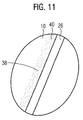
Bezüglich des Implantatsystems wird diese Aufgabe erfindungsgemäß mit den Merkmalen des Anspruchs 1 gelöst. Dabei ist der Verbindungszapfen aus einem Material mit einer Härte von mindestens 500, vorzugsweise von mindestens 750, besonders bevorzugt von mindestens 1000, gebildet und weist in einem Kontaktbereich zum Aufnahmekanal auf seiner Oberfläche eine aus einem im Vergleich zum Material des Verbindungszapfens weicheren Material, insbesondere mit einer Härte von höchstens 25, vorzugsweise von höchstens 20, besonders bevorzugt höchstens 15, gebildete Beschichtung mit einer Schichtdicke von höchstens 0,3 mm, vorzugsweise als Abstandshalter, auf. Zur Herstellung einer stoffschlüssigen Verbindung mit der Beschichtung ist der Verbindungszapfen dabei in seinem mit der Beschichtung versehenen Oberflächenbereich porös, vorzugsweise mit einer Porosität von mindestens 0,1, ausgeführt, wobei die Oberfläche des Verbindungszapfens im Bereich der stoffschlüssigen Verbindung mit der Beschichtung einen ra-Wert von höchstens 10 %, vorzugsweise von höchstens 5 %, der Schichtstärke der Beschichtung aufweist. Mit anderen Worten: Die mittlere Rauigkeit der Oberfläche beträgt vorteilhafterweise höchstens 10 % der Schichtstärke der Beschichtung. Die genannten Härtewerte sind dabei als Härtewerte nach Vickers auf der Basis einer Prüfkraft von 10 kilopond gemäß DIN zu verstehen, d. h. der genannte Härtewert von 500 entspricht beispielsweise einer normgerechten Angabe von 500 HV 10.With regard to the implant system, this object is achieved according to the invention with the features of
Vorteilhafte Ausgestaltungen der Erfindung sind Gegenstand der Unteransprüche.Advantageous embodiments of the invention are the subject of the dependent claims.
Die Erfindung geht von der Überlegung aus, dass bei mehrteiligen Implantatsystemen eine hohe Stabilität und Langlebigkeit dann erreichbar ist, wenn den gerade bei den Kauvorgängen auftretenden Kräften in geeigneter Weise Rechnung getragen wird. Gerade bei der Weiterleitung dieser Kräfte in mehrteiligen Dental-Implantatsystemen vom Aufbauteil in das im Kieferknochen verankerte Pfostenteil sollte eine weitgehend materialschonende Kraftübertragung sichergestellt sein. Dies ist insbesondere erreichbar, indem konsequent ein flächiger Kontakt unter weitgehender Vermeidung lokalisierter Kontaktpunkte zwischen den Implantat-Teilen hergestellt wird. Im Unterschied zu Metall-basierten Systemen, bei denen sich ein solcher flächiger Kontakt auf Grund der höheren elastischen Verformbarkeit und der Duktilität des Materials in Reaktion auf die anliegenden Kräfte nahezu selbsttätig einstellt, könnte der flächige Kontakt in Keramikbasierten Systemen auf Grund der fehlenden Duktilität des Materials und im Hinblick auf nahezu notwendigerweise vorliegende Fertigungstoleranzen und -ungenauigkeiten nur unzureichend sein.The invention is based on the consideration that in multi-part implant systems a high stability and longevity can be achieved if the forces occurring in the chewing processes are taken into account in a suitable manner. Especially in the transmission of these forces in multi-part dental implant systems from Body part in the anchored in the jaw bone post part should be ensured a largely material-friendly power transmission. This is particularly achievable by consistently making a planar contact while largely avoiding localized contact points between the implant parts. In contrast to metal-based systems, in which such surface contact almost automatically occurs due to the higher elastic deformability and the ductility of the material in response to the applied forces, the surface contact in ceramic-based systems could be due to the lack of ductility of the material and be insufficient in view of almost necessarily existing manufacturing tolerances and inaccuracies.
Um dem geeignet entgegenzutreten, ist nunmehr ein zusätzliches Element im Aufbau des Dental-Implantatsystems vorgesehen, das in der Art eines Ausgleichskörpers die Bildung von lokalen, punktuellen Kontaktstellen zwischen den Implantat-Teilen verhindern soll. Der dazu vorgesehene Abstandshalter sollte hinsichtlich seiner Materialwahl derart vorgegeben sein, dass er - auf Grund geeigneter Duktilität - einen geeigneten Ausgleich im Zwischenraum zwischen den Implantat-Teilen herstellt und somit eine flächige Kraftübertragung zwischen den Komponenten gewährleistet. Dazu sollte das Material des Abstandshalters entsprechend weicher und damit verformbarer gewählt sein als das Material der eigentlichen Implantat-Teile.In order to counteract this suitably, an additional element is now provided in the structure of the dental implant system which, in the manner of a compensating body, is intended to prevent the formation of local, point contact points between the implant parts. The spacer provided for this purpose should be predetermined with regard to its choice of material in such a way that-due to suitable ductility-it produces a suitable compensation in the intermediate space between the implant parts and thus ensures a flat force transmission between the components. For this purpose, the material of the spacer should be chosen correspondingly softer and thus deformable than the material of the actual implant parts.
Der Abstandshalter könnte grundsätzlich als Geflecht von ihrerseits mit dem Verbindungszapfens stoffschlüssig verbundenen, also beispielsweise angeklebten oder angeschmolzenen, Materialfäden ausgeführt sein, so dass er insbesondere in Form eines netzartigen Überzugs vorliegt. Auf diese Weise ist einerseits eine zuverlässige Einstellung eines geeigneten, die möglicherweise fertigungsbedingt auftretenden Oberflächenrauigkeiten der Kontaktflächen ausgleichenden Mindestabstands zwischen den Kontaktflächen möglich, wobei andererseits in den durch die Gewebefäden gebildeten Zwischenräumen noch freie, für eine Materialaufnahme geeignete Volumina gebildet werden. Diese eignen sich in besonderem Maße zur Aufnahme überschüssigen Materials, beispielsweise von Klebstoff oder dergleichen. Ein solchermaßen ausgeführter, ebenfalls als erfinderisch angesehener Abstandshalter ist somit für eine Verklebung der Implantat-Teile miteinander besonders geeignet.In principle, the spacer could be designed as a braid by materially bonded to it, that is, for example glued or fused, material threads so that it is present in particular in the form of a net-like coating. In this way, on the one hand a reliable adjustment of a suitable, possibly due to production occurring surface roughness of the contact surfaces balancing minimum distance between the contact surfaces possible, on the other hand, in the spaces formed by the fabric threads still free, suitable for a material intake volumes are formed. These are particularly suitable for absorbing excess material, such as adhesive or the like. Such a done, likewise as spacers considered inventive is thus particularly suitable for bonding the implant parts together.
Nunmehr ist der Abstandshalter aber als auf die Oberfläche des Verbindungszapfens aufgebrachte Beschichtung ausgeführt. Die Beschichtung kann dabei teilweise oder netzartig auf der Oberfläche des Verbindungszapfens angebracht sein, ist vorteilhafterweise aber durchgängig und vollflächig ausgeführt. Damit ergibt sich eine vollflächige Ausführung des Abstandshalters auf dem Verbindungszapfen. In einer solchen Ausführung ist der Abstandshalter für ein Verkleben der Implantat-Teile miteinander ebenso geeignet wie für die Herstellung einer Verbindung durch Verschrauben, da der Abstandshalter in diesem Fall dann auch noch eine Dämpfung bei der Kraftübertragung zwischen den miteinander verschraubten Implantat-Teilen bewirken kann.Now, however, the spacer is designed as applied to the surface of the connecting pin coating. The coating may be partially or web-like mounted on the surface of the connecting pin, but is advantageously carried out continuously and over the entire surface. This results in a full-surface design of the spacer on the connecting pin. In such an embodiment, the spacer for bonding the implant parts together as well as for the preparation of a connection by screwing, since the spacer in this case can then also cause a damping in the power transmission between the screwed together implant parts.
Für eine gute Verarbeitbarkeit ist der Abstandshalter dabei formschlüssig, also insbesondere als Beschichtung oder angeklebtes oder angeschmolzenes Element, mit dem Verbindungszapfen verbunden. Analog kann selbstverständlich der Abstandshalter auch in der Art einer Innenbeschichtung auf der Innenseite des Aufnahmekanals aufgebracht sein, so dass er ebenfalls nach einer Montage der Implantat-Teile im Verbindungsbereich der Implantat-Teile miteinander zwischen diesen positioniert ist. Des Weiteren ist auch eine Kombination zweier Abstandshalter, also jeweils einer an jedem der beiden Implantat-Teile, möglich.For good processability, the spacer is positively connected, ie in particular as a coating or glued or fused element, connected to the connecting pin. Analogously, of course, the spacer may also be applied in the manner of an inner coating on the inside of the receiving channel, so that it is also positioned after mounting the implant parts in the connecting region of the implant parts with each other between them. Furthermore, a combination of two spacers, ie one on each of the two implant parts, is also possible.
Um auch bei einer Montage mit vergleichsweise hohen Presskräften und in kurzer Montagezeit eine zuverlässige Positionierung der den Abstandshalter bildenden Beschichtung und auch eine besondere Langzeitstabilität und ein zuverlässiges Anhaften der Beschichtung zu gewährleisten, ist die stoffschlüssige Verbindung des Abstandshalters mit dem Verbindungszapfen (bzw., in analoger Ausführung, der Innenoberfläche des Aufnahmekanals) besonders innig ausgeführt. Dazu weist der Verbindungszapfen im Bereich seiner Verbindung mit dem Abstandshalter oder im Bereich der Beschichtung eine aufgeraute und/oder poröse Oberfläche auf. Die, insbesondere durch Aufrauung erzeugte Porosität der Oberfläche ist dabei derart ausgestaltet, dass eine poröse Oberfläche gerade im Bereich der stoffschlüssigen Verbindung des Verbindungszapfens mit der Beschichtung entsteht, vorzugsweise mit einer Porosität mit einer Strukturgröße von höchstens einem Mikrometer, alternativ oder zusätzlich bevorzugt mit einer Porosität von mindestens 0,1. Durch eine derartige, porös gehaltene Oberfläche ist sichergestellt, dass gerade in Kombination mit einer geeigneten Materialwahl für die Beschichtung deren Material zumindest teilweise in die porositätsbedingt vorliegenden Hohlräume in der Oberfläche eindringen kann und somit ein besonders inniger Stoffschluss entsteht. Die mit 0,1 angegebene Porosität wurde durch folgende Formel ermittelt: 
Dabei stehen die hierin verwendeten Buchstaben des griechischen Alphabets für: Φ = Porosität, ρ = Rohdichte, ρ0 = Reindichte.The letters of the Greek alphabet used here are: Φ = porosity, ρ = bulk density, ρ 0 = true density.
Dabei ist die Porosität eine dimensionslose Messgröße. Sie stellt das Verhältnis von Hohlraumvolumen zu Gesamtvolumen eines Stoffes oder Stoffgemisches dar und ist als 1 minus dem Quotienten aus Rohdichte eines Festkörpers und Reindichte definiert.The porosity is a dimensionless measurand. It represents the ratio of void volume to total volume of a substance or mixture of substances and is defined as 1 minus the quotient of bulk density of a solid and pure density.
Die vorgesehene Aufrauung wird dabei vorteilhafterweise nach der eigentlichen Herstellung, also insbesondere im Rahmen eines zusätzlichen Behandlungsschritts, auf die Oberfläche aufgebracht. Die Aufrauung kann beispielsweise mechanisch (z. B. durch Bestrahlung wie beispielsweise Sandstrahlen), chemisch (z. B. durch Ätzen) oder durch Bestrahlung mit einem Laser, vorzugsweise mit einem Femtosekunden-Laser, vorgenommen werden. Gerade durch die Bestrahlung mit einem Laser, der eine Pulsdauer von weniger als etwa 1 ps aufweist, können dabei auch gezielte Strukturen oder Strukturmuster auf die zu beschichtende Oberfläche aufgebracht werden, wobei zudem noch eine tiefergehende Beschädigung des darunterliegenden Materials, also insbesondere der Keramik, vermieden werden kann.The intended roughening is advantageously applied to the surface after the actual production, ie in particular within the scope of an additional treatment step. The roughening can be carried out, for example, mechanically (for example by irradiation, for example by sandblasting), chemically (for example by etching) or by irradiation with a laser, preferably with a femtosecond laser. Just by the irradiation with a laser, which has a pulse duration of less than about 1 ps, can also targeted structures or pattern structure be applied to the surface to be coated, which also still a deeper damage to the underlying material, ie in particular the ceramic can be avoided.
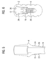
Um eine zuverlässige mechanische Verbindung zwischen den Implantat-Teilen bei hoher Dichtigkeit zu ermöglichen, weist der Verbindungszapfen vorteilhafterweise im Querschnitt eine an die Kontur des zugeordneten Aufnahmekanals angepasste Außenkontur auf. In Längsrichtung von Verbindungszapfen oder Aufnahmekanal gesehen können beide zudem mit gleichbleibendem Querschnitt, also beispielsweise mit zylindrischem Grundkörper, ausgeführt sein. Vorteilhafterweise verjüngen sich die Querschnitte aber in Richtung zum freien Ende des Verbindungszapfens hin, in besonders vorteilhafter Ausgestaltung in konischer Ausführung, so dass sich auf besonders einfache Weise ein guter Kraftschluss bei hoher Dichtigkeit erzielen lässt. In weiterer vorteilhafter Ausgestaltung weist die Außenkontur des Verbindungszapfens - und entsprechend daran angepasst der Aufnahmekanal in seiner Innenkontur - im Querschnitt zumindest teil- oder abschnittsweise eine mehrzählige Symmetrie auf. Damit ist einerseits in der Art einer Indizierung auf einfache Weise eine zuverlässige rotatorische Ausrichtung des Aufbauteils bei der Montage, also bei der Einbringung in den Patientenmund, erreichbar, wobei andererseits in der Art eines rotatorischen Gesperres selbst bei der Einleitung hoher Drehmomente in das System die gewählte rotatorische Ausrichtung in der Zahnumgebung zuverlässig erhalten bleibt.In order to enable a reliable mechanical connection between the implant parts with high tightness, the connecting pin advantageously has, in cross section, an outer contour adapted to the contour of the associated receiving channel. Seen in the longitudinal direction of the connecting pin or receiving channel, both can also be designed with a constant cross-section, that is, for example, with a cylindrical base body. Advantageously, however, the cross-sections taper in the direction of the free end of the connecting pin, in a particularly advantageous embodiment in a conical design, so that in a particularly simple manner good adhesion and high tightness can be achieved. In a further advantageous embodiment, the outer contour of the connecting pin - and adapted accordingly the receiving channel in its inner contour - in cross-section at least partially or in sections a multiple symmetry. This is on the one hand in the manner of indexing in a simple manner a reliable rotational alignment of the body part during assembly, ie when introduced into the patient's mouth, accessible, on the other hand in the manner of a rotary locking mechanism even when the introduction of high torques in the system, the selected Rotational alignment in the dental environment is reliably maintained.
Hinsichtlich seiner Schichtdicke ist der Abstandshalter vorteilhafterweise derart dimensioniert, dass einerseits eine zu große Nachgiebigkeit und Verformbarkeit des montierten Gesamtsystems infolge zu großer Schichtdicke vermieden und andererseits eine zuverlässige Kompensation von Oberflächenrauigkeiten und Fertigungstoleranzen gewährleistet ist. Dabei ist vorzugsweise auch dem Umstand Rechnung getragen, dass gerade bei konischen Verbindungen zwischen dem Aufbauteil und dem Pfostenteil die elastische Verformbarkeit des Pfostenteils zur Kompensation von fertigungsbedingten Winkeltoleranzen bezüglich des Konuswinkels dient. Bei herkömmlichen, metallischen mehrteiligen Implantatsystemen sind die Winkeltoleranzen dabei üblicherweise so dimensioniert, dass der Konuswinkel der Formausnehmung im Pfostenteil kleiner ist als der Konuswinkel des am Aufbauteil angeformten Kontaktstifts.With regard to its layer thickness, the spacer is advantageously dimensioned such that, on the one hand, excessive flexibility and deformability of the assembled overall system due to excessive layer thickness are avoided and, on the other hand, reliable compensation of surface roughness and manufacturing tolerances is ensured. In this case, the fact is also preferably taken into account that just with conical connections between the body part and the post part, the elastic deformability of the post part is used to compensate for production-related angle tolerances with respect to the cone angle. In conventional, metallic multipart implant systems, the angle tolerances are usually dimensioned in this way, the cone angle of the mold cavity in the post part is smaller than the cone angle of the contact pin formed on the body part.
Bei verschraubten Systemen verformt sich dann beim Anziehen der Verbindungsschraube die Wand des Pfostenteils im elastischen Bereich derart, dass es zu einem flächigen Anliegen der Kontaktflächen aneinander kommt. Da dies bei keramischen Materialien auf Grund der mangelnden Verformbarkeit und ihrer großen Härte von (nach Vickers) beispielsweise mehr als 500 oder sogar mehr als 1000 ("Vickershärte", HV) nicht möglich ist, sollte die als Abstandshalter vorgesehene Beschichtung diese Kompensationen ermöglichen. Aus den genannten Gründen ist in vorteilhafter Ausgestaltung im Hinblick auf ansonsten gängige Dimensionierungsparameter der Dental-Implantatsysteme (Gesamtlänge, Durchmesser des Pfostenteils etc.) eine Schichtdicke von mindestens 0,001 mm, vorzugsweise mindestens 0,05 mm, besonders bevorzugt mindestens 0,01 mm, und/oder von höchstens 0,3 mm, vorzugsweise höchstens 0,2 mm, besonders bevorzugt höchstens 0,1 mm, vorgesehen.In bolted systems then deforms when tightening the connecting screw, the wall of the post part in the elastic region such that it comes to a flat concern of the contact surfaces together. Since this is not possible with ceramic materials due to the lack of ductility and their high hardness of (according to Vickers) for example more than 500 or even more than 1000 ("Vickers hardness", HV), the coating provided as a spacer should allow these compensations. For the reasons mentioned in an advantageous embodiment with regard to otherwise common dimensioning parameters of the dental implant systems (total length, diameter of the post part, etc.) has a layer thickness of at least 0.001 mm, preferably at least 0.05 mm, more preferably at least 0.01 mm, and / or of at most 0.3 mm, preferably at most 0.2 mm, particularly preferably at most 0.1 mm.
Hinsichtlich der Materialwahl sind die jeweiligen Komponenten, insbesondere die Implantat-Teile, vorteilhafterweise im Hinblick auf eine hohe Langzeitstabilität gerade im vorgesehenen Einsatzumfeld und auch im Hinblick auf besonders gute Verträglichkeit und Bio-Kompatibilität geeignet gewählt. Für den Abstandshalter könnte dabei beispielsweise ein geeignet gewähltes, insbesondere im Hinblick auf die Materialwahl der eigentlichen Implantat-Teile ausreichend weiches Metall, vorzugsweise Gold, gewählt sein. Um aber auch eine vollständig metallfreie Ausführung des Implantatsystems zu ermöglichen, ist in besonders vorteilhafter Ausgestaltung der Abstandshalter aus einem Kunststoff, vorzugsweise aus einem hochbelastbaren thermoplastischen Kunststoff aus der Gruppe der Polyetherketone, insbesondere aus Polyetheretherketon, auch als PEEK bekannt, hergestellt. PEEK weist üblicherweise eine Härte nach Vickers von etwa 12 auf und erfüllt damit das nun vorgesehene Auslegungskriterium besonders zufriedenstellend.With regard to the choice of material, the respective components, in particular the implant parts, are advantageously selected in view of a high long-term stability, especially in the intended operating environment, and also with regard to particularly good compatibility and biocompatibility. For example, a suitably chosen metal, preferably gold, which is sufficiently soft, in particular with regard to the choice of material of the actual implant parts, could be selected for the spacer. In order to allow a completely metal-free embodiment of the implant system, in a particularly advantageous embodiment of the spacer made of a plastic, preferably made of a high-strength thermoplastic from the group of polyether ketones, in particular polyetheretherketone, also known as PEEK produced. PEEK usually has a hardness of Vickers of about 12 and thus fulfills the now proposed design criterion particularly satisfactory.
In zusätzlicher oder alternativer vorteilhafter Weiterbildung weist der den Abstandshalter bildende Kunststoff einen Elastizitätsmodul von mindestens 1000 MPa auf. Damit ist der Abstandshalter ausreichend hart, um den beim Kauen auftretenden Kräften standzuhalten, so dass eine plastische Verformung und ein "Ausquellen" des Materials vermieden sind.In additional or alternative advantageous development, the plastic forming the spacer has a modulus of elasticity of at least 1000 MPa. Thus, the spacer is sufficiently hard to withstand the forces occurring during chewing, so that a plastic deformation and a "swelling" of the material are avoided.
Um ein Aufquellen des Materials nach dem Einbringen in den Patientenmund und insbesondere eine durch ein derartiges Aufquellen möglicherweise bedingte Rissbildung in den Implantat-Teilen zuverlässig zu vermeiden, weist der den Abstands-halter bildende Kunststoff in zusätzlicher oder alternativer vorteilhafter Ausgestaltung eine Wasseraufnahme von höchstens 1 %, vorzugsweise von höchstens 0,5 %, besonders bevorzugt von höchstens 0,2 %, auf.In order to reliably prevent swelling of the material after introduction into the patient's mouth and in particular due to such a swelling caused cracking in the implant parts, the distance-holder plastic forming in additional or alternative advantageous embodiment, a water absorption of at most 1% , preferably of at most 0.5%, more preferably of at most 0.2%.
Im Hinblick auf allgemein übliche Regelungen und Vorschriften bei der therapeutischen Patientenversorgung sind die Bauteile des Implantatsystems vorteilhafterweise für eine problemlose Sterilisierbarkeit ausgelegt. Hierfür weist der den Abstandshalter bildende Kunststoff vorteilhafterweise eine Erweichungstemperatur von mindestens 140 °C, vorzugsweise von mindestens 160 °C, besonders bevorzugt von 300 °C, auf, so dass ohne Einschränkung gängige Heißdampf-Sterilisationen (üblicherweise bei einer Temperatur von 134 °C) je nach Bedarf einmalig oder auch mehrmalig vorgenommen werden können.With regard to generally customary rules and regulations in therapeutic patient care, the components of the implant system are advantageously designed for easy sterilization. For this purpose, the plastic forming the spacer advantageously has a softening temperature of at least 140 ° C., preferably of at least 160 ° C., more preferably of 300 ° C., so that standard superheated steam sterilizations are carried out without restriction (usually at a temperature of 134 ° C.) can be made once or several times as needed.
Der Verbindungszapfen ist vorzugsweise aus einer Keramik, insbesondere aus Zirkonoxid, gebildet, so dass insgesamt eine hohe Stabilität des Systems gewährleistet ist. Ein derartiger keramischer Verbindungszapfen mit aufgebrachter Oberflächenbeschichtung ist besonders vorteilhaft für eine Verwendung in Kombination mit einem Pfostenteil bzw. Aufnahmekanal aus Titan oder einem anderen metallischen Werkstoff, da grundsätzlich bei der Materialpaarung Keramik/Metall, insbesondere Keramik/Titan, auf Grund der deutlich größeren Härte der Keramik mit Metallabrieb und entsprechenden Oberflächen- und Farbänderungen gerechnet werden muss. Gerade die genannte Keramik weist üblicherweise eine Härte nach Vickers ("Vickershärte", HV) von mehr als 1000 auf. Da die genannten Effekte bereits bei Keramiken mit einer Vickershärte von 500 oder mehr verstärkt auftreten, ist bereits aus diesem Grund der als Zwischen- oder Pufferelement vorgesehene Abstandshalter besonders vorteilhaft. Die genannten Effekte, insbesondere der Oberflächenabrieb, können insbesondere durch die als Abstandshalter zwischen Keramik einerseits und Metall, insbesondere Titan, andererseits wirkende Oberflächenbeschichtung wirksam vermieden werden.The connecting pin is preferably formed of a ceramic, in particular of zirconium oxide, so that overall a high stability of the system is ensured. Such a ceramic connecting pin with applied surface coating is particularly advantageous for use in combination with a post part or receiving channel made of titanium or other metallic material, since basically in the material pairing ceramic / metal, especially ceramic / titanium, due to the significantly greater hardness of Ceramic with metal abrasion and corresponding surface and color changes must be expected. Especially the mentioned ceramic usually has a hardness according to Vickers ("Vickers hardness", HV) of more than 1000 on. Since the mentioned effects occur already amplified with ceramics having a Vickers hardness of 500 or more, the spacer provided as an intermediate or buffer element is already particularly advantageous for this reason. The mentioned effects, in particular the surface abrasion, can be effectively avoided in particular by the surface coating acting as a spacer between ceramic on the one hand and metal, in particular titanium, on the other hand.
In besonders vorteilhafter Ausgestaltung wird aber für die Implantat-Teile insgesamt eine Keramik, insbesondere Zirkonoxid oder Aluminiumoxid, verwendet, jedenfalls als Hauptbestandteil, wodurch ein metallfreier Grundkörper bereitgestellt wird. Derartige Materialien zeichnen sich durch ihre hervorragende Biokompatibilität aus und bieten eine bakterienresistente Oberfläche. In besonders vorteilhafter Ausgestaltung ist dabei der Verbindungszapfen aus Yttrium- und/oder Aluminiumoxid-stabilisiertem Zirkonoxid ausgeführt, wobei in weiterer vorteilhafter Ausgestaltung die Oberfläche des Verbindungszapfens im Bereich der stoffschlüssigen Verbindung mit dem Abstandshalter eine Verarmungszone mit einem im Vergleich zum Innenvolumen des Verbindungszapfens reduziertem Yttrium- bzw. Aluminiumoxid-Anteil aufweist.In a particularly advantageous embodiment, however, a total of one ceramic, in particular zirconium oxide or aluminum oxide, is used for the implant parts, in any case as the main component, as a result of which a metal-free basic body is provided. Such materials are characterized by their excellent biocompatibility and provide a bacteria-resistant surface. In a particularly advantageous embodiment, the connecting pin made of yttrium and / or alumina-stabilized zirconia is carried out, wherein in a further advantageous embodiment, the surface of the connecting pin in the region of the material connection with the spacer a depletion zone with a reduced compared to the inner volume of the connecting pin yttrium or aluminum oxide content.
Zur Herstellung einer derartigen Verarmungszone kann bevorzugt ein Keramik-Grundkörper mittels Laserbehandlung und/oder in einem flüssigen und/oder gasförmigen Medium behandelt werden, vorzugsweise in einem Säurebad, wobei das Säurebad mit Ionen versetzt ist, die jeweils aus einem Element aus einer der V. bis VII. Hauptgruppe des Periodensystems der Elemente bestehen oder ein derartiges Element als Bestandteil umfassen. Durch diese Behandlung ist ein Keramik-körper erhältlich, bei dem in einem Oberflächenbereich hinsichtlich eines Strukturparameters, insbesondere eines Legierungsbestandteils oder eines kristallographischen Phasenanteils, im Vergleich zum Innenvolumen eine Verarmungszone vorliegt.To produce such a depletion zone, a ceramic base body may preferably be treated by means of laser treatment and / or in a liquid and / or gaseous medium, preferably in an acid bath, wherein the acid bath is mixed with ions, each consisting of an element from one of the V. to VII. Main Group of the Periodic Table of the Elements or include such an element as a component. By this treatment, a ceramic body is obtainable in which there is a depletion zone in a surface area with respect to a structural parameter, in particular an alloying constituent or a crystallographic phase fraction, in comparison with the internal volume.
Wie sich völlig überraschend und unerwarteterweise herausgestellt hat, führt gerade dieses Verfahren zur Ausbildung von Oberflächenstrukturen, die besonders günstige Benetzungseigenschaften gewährleisten und bei einer Verwendung des Keramikkörpers als Trägerkörper für den Abstandshalter ein besonders gutes Anhaften der als Abstandshalter vorgesehenen Beschichtung ermöglichen.As has been found, surprisingly and unexpectedly, this process leads to the formation of surface structures which ensure particularly favorable wetting properties and to the use of the ceramic body as a carrier body for the spacer allow a particularly good adhesion of the intended as a spacer coating.
Durch die Behandlung des Keramik-Grundkörpers in der Art des Ätzens und insbesondere des interkristallinen Ätzens bildet sich nämlich eine spezifische Nanostruktur auf der Oberfläche aus. Dabei sind eine Vielzahl vergleichsweise kleinerer Poren oder Vertiefungen mit einer mittleren Ausdehnung im Sub-Mikrometerbereich, vorzugsweise kleiner als 500 nm und insbesondere kleiner 250 nm anzutreffen. Derartige Strukturen können beispielsweise anhand elektronenmikroskopischer Aufnahmen nachgewiesen werden. Die Oberfläche zeichnet sich insbesondere dadurch aus, dass die Tiefe der Nanostruktur, also die Tiefe der dabei erzielbaren Poren, größer ist als die Strukturweite, also die charakteristische laterale Ausdehnung der erzielten Strukturen. Damit ist die vorgesehene Porosität der Oberfläche somit mit für die gewünschte hoch belastbare stoffschlüssige Verbindung besonders günstigen Eigenschaften bereitstellbar.By the treatment of the ceramic base body in the manner of the etching and in particular the intercrystalline etching namely forms a specific nanostructure on the surface. In this case, a multiplicity of comparatively smaller pores or depressions having a mean extent in the sub-micron range, preferably less than 500 nm and in particular less than 250 nm, are to be found. Such structures can be detected for example by means of electron micrographs. The surface is characterized in particular by the fact that the depth of the nanostructure, ie the depth of the thereby obtainable pores, is greater than the structure width, ie the characteristic lateral extent of the structures achieved. Thus, the intended porosity of the surface is thus provided with particularly favorable for the desired high-strength cohesive connection properties.
Das Verhältnis bei der Nanostruktur zwischen der Strukturtiefe und der Strukturweite ist größer als 1:1, vorteilhafterweise größer als 1,5:1 und insbesondere größer als 2:1.The ratio in the nanostructure between the structure depth and the structure width is greater than 1: 1, advantageously greater than 1.5: 1 and in particular greater than 2: 1.
Die vorteilhafterweise vorgesehene Verarmungszone im Oberflächenbereich, die letztendlich die gewünschte Struktur und die gewünschten Eigenschaften bei der Verbindung mit dem Material des Abstandshalters bewirkt, kann insbesondere durch selektives oder zumindest selektiv beschleunigtes Herauslösen einzelner Bestandteile wie beispielsweise chemischer Elemente und/oder Oxide aus der Oberfläche, vorzugsweise durch einen geeignet gewählten Ätzprozess, hergestellt werden. Solch günstige Strukturen können insbesondere geschaffen werden, indem einzelne Elemente und/oder einzelne in der Keramik befindliche Metalloxide (Zirkonoxid, Aluminiumoxid, Yttriumoxid, Hafniumoxid etc.), insbesondere Yttriumoxid und Hafniumoxid, aus der Oberfläche gelöst werden. Somit entsteht auf und/oder im grenznahen Bereich der Oberfläche eine Verarmungszone dieser Metalloxide.The advantageously provided depletion zone in the surface region, which ultimately brings about the desired structure and the desired properties in the connection with the material of the spacer, in particular by selective or at least selectively accelerated dissolution of individual components such as chemical elements and / or oxides from the surface, preferably by a suitably selected etching process. Such favorable structures can be created, in particular, by detaching individual elements and / or individual metal oxides (zirconium oxide, aluminum oxide, yttrium oxide, hafnium oxide, etc.) present in the ceramic, in particular yttrium oxide and hafnium oxide, from the surface. Thus, a depletion zone of these metal oxides is formed on and / or in the vicinity of the surface near the surface.
Weiterhin hat sich bei der Analyse im Hinblick auf die Phaseneigenschaften gezeigt, dass durch eine der oben beschriebenen Behandlungen auf der Oberfläche sich das Verhältnis zwischen der tetragonalen und der monoklinen Phase im stabilisierten Zirkonoxid geändert hat. Nach dem Sintervorgang konnte durch ein solches Verfahren der Anteil der monoklinen Phase in der Oberfläche auf oder um wenigstens 0,1 %, vorteilhafterweise auf oder um mehr als 0,5 % und insbesondere auf oder um mehr als 1,5 % gesteigert bzw. reduziert werden. Da die Oberfläche durch die geringere Dichte der monoklinen Phase unter Druck gesetzt wird, ist auf diesem Wege die initiale Rissbildung gehemmt, so dass mit einer Steigerung der initialen Festigkeit gerechnet werden kann.Further, in the phase property analysis, it has been found that by one of the surface treatments described above, the ratio between the tetragonal and the monoclinic phase in the stabilized zirconia has changed. After the sintering process, the proportion of the monoclinic phase in the surface could be increased or reduced by at least 0.1%, advantageously to or more than 0.5% and in particular to or by more than 1.5% by such a method become. Since the surface is pressurized by the lower density of the monoclinic phase, the initial crack formation is inhibited in this way, so that an increase in the initial strength can be expected.
Die Herstellung der vorgesehenen Verarmungszone in der Oberfläche des Keramikkörpers kann insbesondere durch einen Ätzprozess in einem geeignet gewählten Säurebad erfolgen. Die vorgesehenen Reaktionspartner für die Keramik des Grundkörpers, also die Ionen mit Bestandteilen aus der V. bis VII. Hauptgruppe des Periodensystems der Elemente, können dabei insbesondere als Salzbildner für das jeweilige Metall wirken. Insbesondere kann das Säurebad Ionen umfassen, die aus den Elementen Stickstoff (N), Sauerstoff (O), Fluor (F), Chlor (Cl), Schwefel (S) und/oder Phosphor (P) bestehen oder diese als Bestandteile umfassen. Bei der Behandlung im Säurebad besteht die Möglichkeit, dass die Ionen der Säure die Oberfläche chemisch verändern und als Verunreinigung auf der Oberfläche verbleiben.The preparation of the intended depletion zone in the surface of the ceramic body can be carried out in particular by an etching process in a suitably selected acid bath. The envisaged reactants for the ceramic of the main body, ie the ions with constituents from the fifth to seventh main group of the Periodic Table of the Elements, can act in particular as salt formers for the respective metal. In particular, the acid bath may comprise ions consisting of or comprising as constituents nitrogen (N), oxygen (O), fluorine (F), chlorine (Cl), sulfur (S) and / or phosphorus (P). In acid bath treatment, there is a possibility that the acid ions chemically alter the surface and remain as a contaminant on the surface.
Bezüglich des Verfahrens zur Herstellung eines derartigen Dental-Implantatsystems wird die genannte Aufgabe gelöst, indem der Verbindungszapfen vor der Herstellung der stoffschlüssigen Verbindung mit dem Abstandshalter im Bereich der vorgesehenen Verbindung mit dem Abstandshalter an seiner Oberfläche aufgeraut wird.With regard to the method for producing such a dental implant system, the stated object is achieved by roughening the connecting pin on its surface prior to the production of the integral connection with the spacer in the region of the intended connection with the spacer.
Die Aufrauung kann dabei in vorteilhafter Ausgestaltung durch Laserbestrahlung oder durch Sandstrahlen vorgenommen werden. Besonders vorteilhaft ist aber, wenn der Verbindungszapfen vor der Herstellung der stoffschlüssigen Verbindung mit dem Abstandshalter im Bereich der vorgesehenen Verbindung mit dem Abstandshalter an seiner Oberfläche porös gemacht wird, vorzugsweise durch einen Ätzprozess.The roughening can be made in an advantageous embodiment by laser irradiation or by sandblasting. However, it is particularly advantageous if the connecting pin is made porous on its surface in the region of the intended connection with the spacer on the surface before the bonded connection with the spacer is produced, preferably by means of an etching process.
Zur Aufbringung einer zur Bildung des Abstandshalters vorgesehenen Beschichtung auf den Verbindungszapfen wird vorteilhafterweise auf diesen eine Dispersion aufgebracht, die anschließend getrocknet wird. In der Dispersion werden vorteilhafterweise zur Bildung der Beschichtung vorgesehene Partikel mit einer Partikelgröße von bis zu 20 µm in Lösung vorgehalten. Die Dispersion kann dann aufgesprüht oder auch anderweitig geeignet aufgetragen werden, wobei anschließend vorteilhafterweise ein Trocknungsschritt bei einer Trocknungstemperatur von beispielsweise etwa 150 °C erfolgen kann. Dadurch werden die Lösemittel-Bestandteile verflüchtigt, so dass sich die Materialpartikel niederschlagen und damit die Beschichtung bilden. Die Trocknung erfolgt dabei vorzugsweise im Vakuum oder in Unterdruck, so dass die Bildung von Lufteinschlüssen besonders gering gehalten ist. Insbesondere da derartige Lufteinschlüsse den Eintritt des Materials in die Oberflächenporen des Trägerkörpers blockieren könnten, ist auf diese Weise eine innige stoffschlüssige Verbindung besonders begünstigt.For applying a coating provided for forming the spacer on the connecting pin is advantageously applied to this a dispersion, which is then dried. In the dispersion advantageously provided for the formation of the coating particles are held with a particle size of up to 20 microns in solution. The dispersion can then be sprayed on or otherwise applied in a suitable manner, in which case advantageously a drying step at a drying temperature of, for example, about 150 ° C. can take place. As a result, the solvent components are volatilized, so that the material particles precipitate and thus form the coating. The drying is preferably carried out in vacuo or under reduced pressure, so that the formation of air inclusions is kept particularly low. In particular, since such air pockets could block the entry of the material into the surface pores of the carrier body, in this way an intimate cohesive connection is particularly favored.
In weiterer vorteilhafter Ausgestaltung ist zusätzlich, vorzugsweise nach der Trocknung, eine Wärmebehandlung des mit der Beschichtung versehenen Verbindungszapfens bei einer Behandlungstemperatur oberhalb der Erweichungstemperatur des Beschichtungsmaterials, vorzugsweise von mindestens 350 °C, besonders bevorzugt von mindestens 400 °C, vorgesehen. Damit kann in der Art eines Aufschmelzens des aufgebrachten Materials eine Homogenisierung erfolgen, wobei gegebenenfalls zugleich ein Eindringen des Beschichtungsmaterials in Oberflächenporen oder -rauigkeiten im Verbindungszapfen begünstigt wird. Eine derartige Behandlung ist besonders günstig und wirksam für Schichtdicken bis etwa 0,1 mm. Alternativ könnte für Schichtdicken größer 0,1 mm auch eine Pulverbeschichtung vorgesehen sein.In a further advantageous embodiment, in addition, preferably after drying, a heat treatment of the provided with the coating connection pin at a treatment temperature above the softening temperature of the coating material, preferably of at least 350 ° C, more preferably of at least 400 ° C, is provided. This can be done in the manner of melting the applied material, a homogenization, wherein optionally at the same time a penetration of the coating material is promoted in surface pores or roughnesses in the connecting pin. Such a treatment is particularly favorable and effective for layer thicknesses up to about 0.1 mm. Alternatively, a powder coating could be provided for layer thicknesses greater than 0.1 mm.
Die mit der Erfindung erzielten Vorteile bestehen insbesondere darin, dass durch den im Verbindungsbereich von Verbindungszapfen und Aufnahmekanal vorgesehenen Abstandshalter Ungenauigkeiten und Fertigungstoleranzen bei den Bauteilen ausgeglichen werden können, so dass auch bei Verwendung keramischer Materialien für den Verbindungszapfen oder auch die Implantat-Teile insgesamt ein flächiger Kontakt zwischen diesen Teilen hergestellt werden kann. Hierdurch ist selbst im Hinblick auf die auftretenden hohen Kaukräfte eine materialschonende und zuverlässige Weiterleitung der Kräfte möglich, so dass der Einsatz der an sich wünschenswerten keramischen Materialien auch in mehrteiligen Dental-Implantat-systemen ermöglicht ist.The advantages achieved by the invention are, in particular, that inaccuracies and manufacturing tolerances in the components can be compensated for by the spacers provided in the connecting region of connecting pin and receiving channel, so that even when using ceramic materials for the connecting pin or the implant parts as a whole Contact between These parts can be produced. In this way, even with regard to the high chewing forces occurring, a material-sparing and reliable forwarding of the forces is possible, so that the use of the ceramic materials which are in themselves desirable is also possible in multi-part dental implant systems.
Auch in anderen Einsatzgebieten von keramischen Werkstoffen, insbesondere auf Zirkonoxidbasis, ist eine zumindest im Oberflächenbereich vorgesehene Porosität von mindestens 0,1 besonders vorteilhaft, um eine haftende Beschichtung aus einem Kunststoff, insbesondere PEEK, aufbringen zu können. Die Vorteile einer Beschichtung auf Kunststoffbasis auf einem keramischen Grundkörper liegen insbesondere in der Veränderung der chemischen Eigenschaften und insbesondere der Säurebeständigkeit. Bezüglich der mechanischen Eigenschaftsänderungen sind insbesondere die optimierte Krafteinleitung /Kraftübertragung zu nennen. Aber auch die Veränderung des Reibwerts p mittels einer haftenden Beschichtung verschafft keramischen Werkstoffen deutliche Vorteile in der Anwendbarkeit, insbesondere im Vergleich zu anderen metallischen Werkstoffen.In other fields of application of ceramic materials, in particular based on zirconium oxide, a porosity of at least 0.1, provided at least in the surface area, is particularly advantageous in order to be able to apply an adhesive coating of a plastic, in particular PEEK. The advantages of a plastic-based coating on a ceramic base body are in particular the change in the chemical properties and in particular the acid resistance. With regard to the mechanical property changes, in particular the optimized introduction of force / force transmission must be mentioned. But even the change of the coefficient of friction p by means of an adhesive coating provides ceramic materials significant advantages in the applicability, especially in comparison to other metallic materials.
Ein Ausführungsbeispiel der Erfindung wird anhand einer Zeichnung näher erläutert. Darin zeigen:
- FIG. 1 bis 3
- jeweils ein Dental-Implantatsystem als Explosionszeichnung,
- FIG. 4
- das Dental-Implantatsystem nach
FIG. 3 im Längsschnitt, - FIG. 5
- ein Aufbauteil des Dental-Implantatsystems nach
FIG. 1 bis 3 im Querschnitt, - FIG. 6
- ein Pfostenteil des Dental-Implantatsystems nach
FIG. 1 bis 3 im Querschnitt, - FIG. 7, 8
- ein Aufbauteil des Dental-Implantatsystems nach
FIG. 1 bis 3 in seitlicher Ansicht, - FIG. 9, 10
- jeweils eine alternative Ausführungsform eines Dental-Implantatsystems, und
- FIG. 11
- im Ausschnitt den Verbindungsbereich der Komponenten des Dental-Implantatsystems.
- FIG. 1 to 3
- each a dental implant system as an exploded view,
- FIG. 4
- the dental implant system after
FIG. 3 in longitudinal section, - FIG. 5
- a construction part of the dental implant system according to
FIG. 1 to 3 in cross section, - FIG. 6
- a post part of the dental implant system according to
FIG. 1 to 3 in cross section, - FIG. 7, 8
- a construction part of the dental implant system according to
FIG. 1 to 3 in lateral View, - FIG. 9, 10
- in each case an alternative embodiment of a dental implant system, and
- FIG. 11
- in section the connection area of the components of the dental implant system.
Gleiche Teile sind in allen Figuren mit denselben Bezugszeichen versehen.Identical parts are provided with the same reference numerals in all figures.
Das Dental-Implantatsystem 1, 1', 1" gemäß den
Um nach geeigneter Anbringung des Zahnersatzstücks oder der Prothese am Aufbauteil oder zweiten Implantat-Teil 4 ein Einbringen in das Pfostenteil oder erste Implantat-Teil 2, 2', 2" bei hoher mechanischer Stabilität zu ermöglichen, ist an das zweite Implantat-Teil 4 ein Verbindungszapfen 10 angeformt, der in einen zugeordneten, im ersten Implantat-Teil 2, 2', 2" vorgesehenen Aufnahmekanal 12 einschiebbar ist. Durch das Einschieben des Verbindungszapfens 10 in den Aufnahmekanal 12 entsteht eine mechanische Verbindung der Implantat-Teile 2, 4 miteinander. Für eine hohe mechanische Stabilität ist dabei der Verbindungszapfen 10 in seiner Außenkontur an die Innenkontur des Aufnahmekanals 12 angepasst, wobei beide in Längsrichtung gesehen konisch geformt sein können (Ausführungsbeispiel gemäß
Die Dental-Implantatsysteme 1, 1', 1" in den Ausführungsbeispielen gemäß
Hinsichtlich ihrer Materialwahl sind die Implantat-Teile 2, 4 geeignet an den Einsatzzweck angepasst und grundsätzlich aus keramischem Material wie beispielsweise Zirkonoxid oder Aluminiumoxid gefertigt. Insbesondere ist als Material für den Verbindungszapfen 10 Yttrium-stabilisiertes Zirkonoxid gewählt. Dieses weist eine vergleichsweise große Härte von 1500 +- 100 nach Vickers ("Vickershärte", HV) auf. Wegen der geringen elastischen und der mangelnden plastischen Verformbarkeit eines derartig harten Materials ist jedoch davon auszugehen, dass ein flächiger Kontakt der Implantat-Teile 2, 4 miteinander gerade im Bereich des Verbindungszapfens 10 nicht vorliegt. Gerade bei der Übertragung der vergleichsweise großen Kaukräfte können damit punktuelle Belastungen im Kontaktbereich der Implantatteile 2, 4 auftreten. Diese könnten wiederum in erhöhtem lokalem Druck im Verbindungsbereich und demzufolge zur möglichen Bildung von Mikrorissen oder Beschädigungen in der Keramikstruktur resultieren, die wiederum zu Frakturen oder Brüchen in den Bauteilen an sich führen können. Des weiteren könnte - gerade bei einer Kombination eines keramischen Verbindungszapfens 10 mit einem metallischen Pfostenteil 4 - auf Grund des großen Härteunterschieds zwischen den Komponenten Metallabrieb am Pfostenteil auftreten, der zu unerwünschten Verunreinigungen und/oder Verfärbungen oder dergleichen führen könnte.With regard to their choice of material, the
Um dem geeignet entgegenzutreten, ist als zusätzliches Element im Aufbau des Dental-Implantatsystems 1, 1', 1" in der Art eines Ausgleichskörpers oder Abstandshalters 22 der Verbindungszapfen 10 in einem Kontaktbereich zum Aufnahmekanal 12 auf seiner Oberfläche 24 mit einer Beschichtung 26 versehen, wie dies in der Querschnittszeichnung gemäß
Selbstverständlich kann die Beschichtung 26 bei gleicher Wirkung alternativ oder zusätzlich auch auf der Innenoberfläche 28 des Aufnahmekanals 12 im Pfostenteil 2 oder zweiten Implantat-Teil 4 angeordnet sein, wie dies in der Querschnittszeichnung in
Vorzugsweise ist die zur Bildung des Abstandshalters 22 vorgesehene Beschichtung 26 durchgehend in der Art einer vollflächigen Beschichtung ausgeführt. Alternativ kann sie aber auch in der Art eines den Verbindungszapfen 10 umschließenden Netzes, Geflechts oder dergleichen eine Mehrzahl von Teilelementen oder Teilbeschichtungen 30 umfassen, die unter Bildung von Zwischenräumen 32 als netzartiges Gebilde (
In beiden bevorzugten Varianten, also sowohl bei einer Ausführung als durchgehende, vollflächige Beschichtung 26 als auch bei einer Ausgestaltung mit Zwischenräumen 32, ist eine innige stoffschlüssige Verbindung zwischen dem Verbindungszapfen 10 bzw. der Innenoberfläche 28 des Aufnahmekanals 12 einerseits und der den Abstandshalter 22 bildenden Beschichtung 26 andererseits vorgesehen. Um dies besonders zu begünstigen, ist dabei die Oberfläche des Verbindungszapfens 10 im Bereich der Beschichtung aufgeraut und/oder porös ausgeführt. Wie dies in
In der ausschnittsweise vergrößerten Darstellung in
- 1, 1 ', 1"1, 1 ', 1 "
- Dental-ImplantatsystemDental Implant System
- 2, 2', 2"2, 2 ', 2 "
- erstes Implantat-Teilfirst implant part
- 44
- zweites Implantat-Teilsecond implant part
- 66
- Außengewindeexternal thread
- 88th
- apikales Endeapical end
- 1010
- Verbindungszapfenconnecting pins
- 1212
- Aufnahmekanalreceiving channel
- 1414
- Indizierungselementindexing element
- 1616
- EndkanalstückEndkanalstück
- 1818
- Verbindungsschraubeconnecting screw
- 2020
- Schraubgewindescrew thread
- 2222
- Abstandshalterspacer
- 2424
- Oberflächesurface
- 2626
- Beschichtungcoating
- 2828
- Innenoberflächeinner surface
- 3030
- Teilbeschichtungpart Finish
- 3232
- Zwischenraumgap
- 3434
- Aufnahmekammerreceiving chamber
- 3636
- Nutgroove
- 3838
- Materialkammermaterial chamber
- 4040
- Verbindungszoneconnecting zone
Claims (14)
- A dental implant system (1, 1', 1") having a first implant part (2, 2', 2") provided for introduction into a jawbone and having a second implant part (4) associated therewith and provided for attachment of a dental prosthesis piece, wherein the implant parts (2, 2', 2", 4) can be mechanically connected to each other by means of a connecting stud (10) which is formed on one of the implant parts (2, 2', 2", 4) and can be inserted into a receiving channel (12) provided in the other implant part (2, 2', 2", 4), wherein the connecting stud (10) is made of a material with a hardness (according to Vickers) of at least 500 and in a contact region with the receiving channel (12) is provided on its surface with a coating (26) having a layer thickness of at most 0.3 mm and made of a material which is softer as compared with the material of the connecting stud (10), wherein the connecting stud (10) has in its surface region provided with the coating (26) a porous surface for forming a substance-locking connection with the coating (26), and wherein the surface of the connecting stud (10) has in the region of the substance-locking connection with the coating (26) a roughness value of at most 10 % of the layer thickness.
- The dental implant system (1, 1', 1 ") of claim 1, wherein the connecting stud (10) is designed as a ceramic body, wherein the porous surface is generated by means of an etching process and has a nanostructure with a multitude of pores or indentations with a mean extension of less than 500 nm.
- The dental implant system (1, 1', 1 ") of claim 1 or 2, wherein the connecting stud (10) has in its surface region provided with the coating (26), below the coating (26), a connecting region (40) in which material from the coating (26) penetrates into the pores and surface holes of the porous surface of the connecting stud (10), and the materials from the connecting stud (10), on the one hand, and of the coating (26), on the other hand, are together present within the connecting region (40), so that they form an intimate interleaving.
- The dental implant system (1, 1', 1 ") of any of claims 1 to 3, wherein the porous surface of the connecting stud (10) has a porosity of at least 0.1.
- The dental implant system (1, 1', 1 ") of any of claims 1 to 4, whose coating (26) consists of a number of partial coatings (30) which are connected with the connecting stud (10) in a substance-locking manner.
- The dental implant system (1, 1', 1 ") of any of claims 1 to 5, whose coating (26) has a layer thickness of at least 0.001 mm, preferably at least 0.05 mm, particularly preferably at least 0.01 mm, and/or of at most 0.2 mm, particularly preferably at most 0.1 mm.
- The dental implant system (1, 1', 1 ") of any of claims 1 to 6, wherein the coating (26) is made of a synthetic material with a modulus of elasticity of at least 1000 MPa.
- The dental implant system (1, 1', 1 ") of claim 7, wherein the synthetic material forming the coating (26) has a water absorption of at most 1 %, preferably at most 0.5 %, particularly preferably at most 0.2 %.
- The dental implant system (1, 1', 1 ") of claim 7 or 8, wherein the synthetic material forming the coating (26) has a softening temperature of at least 140 °C, preferably at least 180 °C, particularly preferably 300 °C.
- The dental implant system (1, 1', 1 ") of any of claims 1 to 9, wherein the surface of the connecting stud (10) has in the region of the substance-locking connection with the coating (26) a roughness value of at most 5 % of the layer thickness.
- The dental implant system (1, 1', 1 ") of any of claims 1 to 10, whose connecting stud (10) is made of yttrium oxide and/or aluminium oxide-stabilized zirconium oxide, wherein the surface of the connecting stud (10) has in the region of the substance-locking connection with the coating (26) a depletion region with a share of yttrium oxide or aluminium oxide which is reduced as compared with the inner volume of the connecting stud.
- A method for producing a dental implant system (1, 1', 1") of any of claims 1 to 11, wherein the connecting stud (10) is roughened on its surface in the region of the intended connection with the coating (26), prior to the production of the substance-locking connection with the coating (26).
- The method of claim 12, wherein the connecting stud (10) is subjected to an etching process.
- The method of any of claims 12 to 13, wherein, for applying the coating (26) on the connecting stud (10), a dispersion is applied, which is then dried.
Applications Claiming Priority (2)
| Application Number | Priority Date | Filing Date | Title |
|---|---|---|---|
| DE102010051176A DE102010051176A1 (en) | 2010-11-15 | 2010-11-15 | Dental implant system and method for producing a dental implant system |
| PCT/EP2011/005748 WO2012065718A1 (en) | 2010-11-15 | 2011-11-15 | Dental implant system and method for producing a dental implant system |
Publications (2)
| Publication Number | Publication Date |
|---|---|
| EP2640306A1 EP2640306A1 (en) | 2013-09-25 |
| EP2640306B1 true EP2640306B1 (en) | 2016-02-10 |
Family
ID=45470500
Family Applications (1)
| Application Number | Title | Priority Date | Filing Date |
|---|---|---|---|
| EP11807636.3A Active EP2640306B1 (en) | 2010-11-15 | 2011-11-15 | Dental implant system and method for producing a dental implant system |
Country Status (8)
| Country | Link |
|---|---|
| US (1) | US9770311B2 (en) |
| EP (1) | EP2640306B1 (en) |
| CN (1) | CN103327928B (en) |
| BR (1) | BR112013011856B1 (en) |
| CA (1) | CA2817860C (en) |
| DE (1) | DE102010051176A1 (en) |
| ES (1) | ES2573681T3 (en) |
| WO (1) | WO2012065718A1 (en) |
Families Citing this family (22)
| Publication number | Priority date | Publication date | Assignee | Title |
|---|---|---|---|---|
| DE102006018726B4 (en) * | 2006-04-20 | 2019-01-31 | Holger Zipprich | Method for producing a dental implant |
| US20130108984A1 (en) | 2010-05-05 | 2013-05-02 | Holger Zipprich | Dental implant |
| DE102011009906A1 (en) | 2011-01-31 | 2012-08-02 | Holger Zipprich | Dental implant system |
| EP2502600A1 (en) | 2011-03-21 | 2012-09-26 | Biodenta Swiss AG | Dental implant system |
| ITMO20130198A1 (en) * | 2013-07-10 | 2015-01-11 | Calvi Raffaella | DEVICE FOR DENTAL IMPLANTOLOGY |
| IL230833A0 (en) | 2014-02-05 | 2014-09-30 | Ophir Fromovich | Bone implant anchor |
| CN107106267B (en) * | 2014-11-06 | 2021-03-09 | 艾皮法诺斯蒂克斯公司 | Single tooth implant in bone |
| JPWO2017002223A1 (en) * | 2015-07-01 | 2017-07-13 | 株式会社ナントー | Implants, fixtures, abutments |
| BR112017025452B1 (en) | 2015-07-24 | 2021-05-04 | Nobel Biocare Services Ag | adapter for connecting a first dental component to a second dental component, and dental assembly comprising the adapter |
| US20170056134A1 (en) * | 2015-08-28 | 2017-03-02 | Zimmer, Inc. | Dental abutments and associated systems and methods |
| CH711879B1 (en) * | 2015-12-08 | 2023-05-31 | Z Systems Ag | dental implant system. |
| SE1651462A1 (en) | 2016-11-08 | 2017-10-31 | Integrum Ab | Anchoring system for attaching a prosthesis to a human body |
| US20180266325A1 (en) * | 2017-03-20 | 2018-09-20 | General Electric Company | Extraction cooling system using evaporative media for stack cooling |
| US20180333237A1 (en) * | 2017-04-22 | 2018-11-22 | Fereidoun Daftary | Apparatus and method for anatomic restoration dental implant having a two-piece reinforced zirconium dioxide base and titanium insert |
| DE102017113148A1 (en) * | 2017-06-14 | 2018-12-20 | Bredent Gmbh & Co. Kg | Fastening device for a dental prosthesis |
| IT201700077841A1 (en) * | 2017-07-11 | 2019-01-11 | Sweden & Martina Spa | IMPROVED DENTAL SYSTEM WITH DIFFERENTIAL MATERIAL INSERT |
| KR102055821B1 (en) * | 2017-09-18 | 2019-12-16 | 오스템임플란트 주식회사 | A dental implant assembly and a method for manufacturing the same |
| EP3520730A1 (en) | 2018-02-02 | 2019-08-07 | VITA-ZAHNFABRIK H. Rauter GmbH & Co. KG | Holding device for tooth replacement elements |
| JP7195523B2 (en) * | 2018-08-08 | 2022-12-26 | 株式会社トクヤマデンタル | Method for manufacturing dental prosthesis |
| US11672632B2 (en) | 2020-10-05 | 2023-06-13 | Pritidenta Gmbh | Multi-layered zirconia dental blank with reverse layers, process for its preparation and uses thereof |
| US20220202539A1 (en) * | 2020-12-30 | 2022-06-30 | Industrial Technology Research Institute | Dental implant |
| CN114392392A (en) * | 2022-02-15 | 2022-04-26 | 西南科技大学 | Preparation method of personalized and customized polyether-ether-ketone implanted prosthesis with high biological activity |
Family Cites Families (102)
| Publication number | Priority date | Publication date | Assignee | Title |
|---|---|---|---|---|
| US4270905A (en) * | 1979-02-21 | 1981-06-02 | Mohammed M Hamdi A | Replacement system for dental and other bone implants |
| CH642838A5 (en) | 1979-11-21 | 1984-05-15 | Osteo Ag | JAW IMPLANT. |
| US4876148A (en) * | 1984-10-29 | 1989-10-24 | Ceramatec, Inc. | Ceramic bodies having a plurality of stress zones |
| DE3571754D1 (en) * | 1984-11-09 | 1989-08-31 | Implanto Lock Gmbh | Endosseous implant for securing fixed or removable dentures |
| DE3531389A1 (en) | 1985-09-03 | 1987-03-05 | Kirsch Axel | ENOSSAL IMPLANT |
| US5015186A (en) | 1987-09-24 | 1991-05-14 | Detsch Steven G | Dental implant attachment system |
| US4854872B1 (en) | 1987-09-24 | 1995-06-27 | Steven G Detsch | Prosthetic implant attachment system and method |
| US4850870C1 (en) | 1987-10-23 | 2001-07-24 | Implant Innovations Inc | Prosthodontic restoration components |
| US4832601A (en) | 1987-12-04 | 1989-05-23 | Hall Surgical | Adjustable support for a prosthetic tooth and method |
| DE69027061T2 (en) * | 1989-06-30 | 1997-01-02 | Tdk Corp | Substitute material for living hard tissue, its manufacture and manufacture of a shaped body |
| US5209666A (en) | 1990-05-15 | 1993-05-11 | Calcitek, Inc. | Endosseous implant system wtih captured screw |
| US5135395A (en) | 1990-07-05 | 1992-08-04 | Marlin Gerald M | Implant collar and post system |
| FR2664808A1 (en) | 1990-07-23 | 1992-01-24 | Gersberg Eduardo | System of dental implants |
| US5281140A (en) | 1991-01-02 | 1994-01-25 | Core-Vent Corporation | Multi-part, multi-positionable abutment for use with dental implants |
| EP0545718A3 (en) * | 1991-12-03 | 1993-10-13 | Janome Sewing Machine Co., Ltd. | Method of making bone-implants |
| AU3803193A (en) * | 1991-12-30 | 1994-09-26 | Wellesley Research Associates, Inc. | Dental implant system and apparatus |
| US5302126A (en) | 1992-03-19 | 1994-04-12 | Park Dental Research Corp. | Dental implant with adjustable post |
| JPH0737805B2 (en) | 1992-11-17 | 1995-04-26 | 有限会社新城製作所 | Recessed screw and its driver bit |
| US5246370A (en) | 1992-11-27 | 1993-09-21 | Coatoam Gary W | Dental implant method |
| US5425639A (en) * | 1994-05-03 | 1995-06-20 | Anders; Irving | Dental implant with shock absorbent cushioned interface |
| CN2216818Y (en) * | 1994-10-10 | 1996-01-10 | 刘华松 | Hollow and column like combition type artificial teeth for dental implant |
| ATE190211T1 (en) * | 1994-10-17 | 2000-03-15 | Degussa | TWO-PHASE DENTAL IMPLANT |
| US6652765B1 (en) | 1994-11-30 | 2003-11-25 | Implant Innovations, Inc. | Implant surface preparation |
| US5989026A (en) | 1995-05-25 | 1999-11-23 | Implant Innovations, Inc. | Ceramic two-piece dental abutment |
| KR19990014953A (en) | 1995-05-25 | 1999-02-25 | 키어스 디 비티 | Anti-rotation coupling mechanism |
| IL123698A0 (en) | 1995-10-13 | 1998-10-30 | Straumann Inst Ag | Connection arrangement between an implant and an abutment |
| EP1518511B1 (en) | 1996-04-04 | 2007-01-10 | Julian Osorio | Customized dental abutment |
| US5785525A (en) | 1996-05-17 | 1998-07-28 | Weissman; Bernard | Dental implant system |
| SE507360C2 (en) | 1996-09-24 | 1998-05-18 | Nobel Biocare Ab | Device for systems with assortment of dental screws and assortment of dental screws |
| US5782918A (en) | 1996-12-12 | 1998-07-21 | Folsom Metal Products | Implant abutment system |
| US5766179A (en) | 1997-03-05 | 1998-06-16 | Orthofix S.R.L. | Mechanical system for blind nail-hole alignment of bone screws |
| US6217331B1 (en) | 1997-10-03 | 2001-04-17 | Implant Innovations, Inc. | Single-stage implant system |
| US5954505A (en) * | 1998-03-05 | 1999-09-21 | Ford; Christopher W. | Force distributing dental implant |
| AU3555299A (en) | 1998-04-13 | 1999-11-01 | Implant Innovations, Inc. | Stepless adjustment of angular orientation of abutment for dental implant |
| US6287115B1 (en) | 1998-11-17 | 2001-09-11 | L. Paul Lustig | Dental implant and tool and method for effecting a dental restoration using the same |
| US6158310A (en) | 1999-05-24 | 2000-12-12 | Textron Inc. | Drive system having a strengthened drive system member for resisting torsional stresses |
| CH694571A5 (en) | 1999-06-21 | 2005-04-15 | Dcs Forschungs & Entwicklungs | A method for producing a dental prosthesis and a dental prosthesis, material for a dental prosthesis and dental prosthesis. |
| DE19941410B4 (en) * | 1999-08-31 | 2011-05-05 | STE Gesellschaft für Dichtungstechnik mbH | Coating and process for its production |
| DE19959366A1 (en) | 1999-12-09 | 2001-06-13 | Stefan Wintermantel | Implant structure for enossal (in-bone) tooth implant is connectable to implant by screw and comprises post together with connecting part applicable to implant basal to post |
| AUPQ817900A0 (en) | 2000-06-16 | 2000-07-06 | Nichinonni, Gianni | Dental implant abutment |
| US6375464B1 (en) | 2000-09-25 | 2002-04-23 | Biolok International, Inc. | Micromechanical seal for dental implant systems |
| GB0108551D0 (en) | 2001-04-05 | 2001-05-23 | Osseobiotek Ltd | Implant |
| US20030013068A1 (en) | 2001-07-16 | 2003-01-16 | Gittleman Neal B. | Trans-tissue extension apparatus |
| US6537069B1 (en) | 2001-10-01 | 2003-03-25 | Earl Wayne Simmons, Jr. | Method and apparatus for dental implants |
| US6733292B2 (en) | 2002-04-15 | 2004-05-11 | Park Avenue Periodontal Associates, P.C. | Universal implant |
| US6575057B1 (en) | 2002-04-18 | 2003-06-10 | Lisle Corporation | Broken heater hose coupler removal tool and method of use |
| DE20209170U1 (en) * | 2002-06-12 | 2004-02-19 | Dinkelacker, Wolfgang, Dr.med.dent. | bone implant |
| SE522501C2 (en) | 2002-06-27 | 2004-02-10 | Nobel Biocare Ab | Preferably completely spaced ceramic spacer with adapter |
| SE523288C2 (en) | 2002-07-19 | 2004-04-06 | Astra Tech Ab | An implant and a method of treating an implant surface |
| US7059854B2 (en) * | 2002-12-23 | 2006-06-13 | Wen-Yuen Wu | Abutment structure used exclusively in tooth implantation |
| CH696625A5 (en) * | 2003-01-02 | 2007-08-31 | Matthias Dr Loppacher | Dental implant with joint without micro gaps has layer between implant body, implant structure that deforms when assembling implant structure on body to give close, gap-free connection in external area where contact with fabric occurs later |
| EP1626670A2 (en) | 2003-02-21 | 2006-02-22 | Ralf Schröder | Dental implant comprising a base body and implant post and corresponding base body and implant post |
| JP2006520249A (en) | 2003-03-13 | 2006-09-07 | ヨン−グ ホ | Screw / cement maintenance type prosthesis treatment method, screw / cement maintenance type prosthesis abutment and implant |
| US7104797B2 (en) | 2003-03-18 | 2006-09-12 | Jeff Rassoli | Rotationally immobilized dental implant and abutment system |
| US7179088B2 (en) | 2003-03-18 | 2007-02-20 | Cagenix, Inc. | Lobed dental implant |
| EP1493399A1 (en) | 2003-06-30 | 2005-01-05 | Ten Bruggenkate Kaakchirurgie B.V. | Intra-osseous implant |
| DE10340059A1 (en) | 2003-07-24 | 2005-02-10 | Schröder, Ralf, Dr. | Dental implant with hollow ceramic body fitting into tooth has tube fitting concentrically inside it with female thread for engaging end of head screw with shoulder engaging upper portion |
| PT1529498E (en) * | 2003-11-05 | 2014-09-17 | Dentsply Implants Mfg Gmbh | Multi part non metal implant |
| EP1547543A1 (en) | 2003-12-23 | 2005-06-29 | Steffen Dr. Heitland | Abutment for dental implants |
| US20050166724A1 (en) | 2004-01-29 | 2005-08-04 | Hand Innovations, Inc. | Twisted and tapered driver for a threaded fastener |
| AR043256A1 (en) | 2004-02-20 | 2005-07-20 | Odontit S A | A DENTAL IMPLANT PROVISION INTEGRATED TO THE BONE TO SUSTAIN A DENTAL PROTESIS |
| US7249949B2 (en) | 2004-06-29 | 2007-07-31 | Lifecore Biomedical, Inc. | Internal connection dental implant |
| US7785107B2 (en) | 2005-02-01 | 2010-08-31 | Niznick Gerald A | Multi-functional fixture mount |
| DE102005005402B4 (en) * | 2005-02-05 | 2011-02-17 | Friadent Gmbh | Dental implant and implant system |
| DE102005008273A1 (en) * | 2005-02-22 | 2006-08-24 | Mundorf, Sönke, Dr. | Tooth implant comprises a bone anchoring part having an outer surface for anchoring in the jawbone and formed as a tissue anchoring part and a tooth alignment part fixed to the bone anchoring part on which a crown is fixed |
| ES2307352B1 (en) | 2005-04-12 | 2009-09-18 | Bti, I+D, S.L. | DENTAL IMPLANT AND PARTS INTENDED TO BE CONNECTED TO A DENTAL IMPLANT, AND THE INTERNAL CONNECTION BETWEEN THE DENTAL IMPLANT AND EACH PIECE. |
| US7225710B2 (en) | 2005-05-27 | 2007-06-05 | Synthes Gmbh | Combination driver and combination fastener |
| ES2415737T3 (en) | 2005-06-03 | 2013-07-26 | Straumann Holding Ag | Coupling for a multi-part dental implant system |
| KR100696324B1 (en) | 2005-07-15 | 2007-03-19 | 이석원 | Implant device for dental surgery |
| US20070037121A1 (en) | 2005-08-10 | 2007-02-15 | Carter Robert D | Carry and drive device and method for dental implant and/or components thereof |
| PL1757245T3 (en) | 2005-08-22 | 2011-01-31 | Riemser Pharma Gmbh | Dental implant |
| WO2007031562A2 (en) * | 2005-09-16 | 2007-03-22 | Mehrhof Juergen | Two-part dental implant |
| US7758344B2 (en) | 2005-11-18 | 2010-07-20 | Form And Function Dental Services, P.C. | Asymmetrical dental implant and method of insertion |
| CN101360465A (en) * | 2005-11-22 | 2009-02-04 | 史密丝克莱恩比彻姆公司 | Adhesive liner |
| DE102006018726B4 (en) | 2006-04-20 | 2019-01-31 | Holger Zipprich | Method for producing a dental implant |
| EP2040638A1 (en) * | 2006-07-13 | 2009-04-01 | Vita Zahnfabrik H. Rauter GmbH & Co. KG | Tooth implant with machinable construction |
| EP2543333B1 (en) * | 2006-07-25 | 2023-08-30 | Holger Zipprich | Method of manufacturing an implant body and implant comprising such a body implant |
| DE102006036020A1 (en) | 2006-08-02 | 2008-02-07 | Borrmann, Igor, Dr. | Enossal tooth implant for use at jaw-bone of e.g. human body, has anchorage part with retainer in form of opening and abutment cemented in retainer and serving as carrier for dental prosthesis that is to be connected with implant |
| ATE441378T1 (en) * | 2007-04-19 | 2009-09-15 | Straumann Holding Ag | METHOD FOR PROVIDING A TOPOGRAPHY ON THE SURFACE OF A DENTAL IMPLANT |
| US8038442B2 (en) | 2007-04-23 | 2011-10-18 | Nobel Biocare Services Ag | Dental implant and dental component connection |
| US8347761B2 (en) | 2007-05-21 | 2013-01-08 | Acument Intellectual Properties, Llc | Drive socket design for hold and drive fastener |
| EP2011779A1 (en) * | 2007-07-06 | 2009-01-07 | Vita Zahnfabrik H. Rauter GmbH & Co. KG | Ceramic body and method for its production |
| KR101240116B1 (en) * | 2007-07-16 | 2013-03-07 | 덴탈포인트 아게 | Dental implant |
| US20090035722A1 (en) * | 2007-08-01 | 2009-02-05 | Ganesan Balasundaram | Hydroxyapatite coated nanostructured titanium surfaces |
| US20090075236A1 (en) | 2007-09-18 | 2009-03-19 | Towse Ross W | Dental implant having improved stability |
| DE102007044852B4 (en) * | 2007-09-20 | 2013-12-24 | Gebr. Brasseler Gmbh & Co. Kg | Dental implant |
| US20090123891A1 (en) * | 2007-11-14 | 2009-05-14 | Rosenberg Jeffrey M | Composite dental implant system |
| US8066511B2 (en) | 2008-03-18 | 2011-11-29 | Woehrle Peter | Asymmetrical dental implant |
| EP2106767A1 (en) * | 2008-03-31 | 2009-10-07 | Ziterion GmbH | Two-part dental implant |
| US8545222B2 (en) * | 2008-10-21 | 2013-10-01 | Chan Qian Wang | Method of dental implant restoration |
| DE102008054138B4 (en) | 2008-10-31 | 2018-01-11 | Holger Zipprich | Dental implant |
| NL1036155C (en) * | 2008-11-05 | 2010-05-06 | Eazy2 Implant Innovations B V | INPUT PART OF A TWO PART IMPLANT WITH INPUT INSTRUMENT. |
| IL196872A0 (en) | 2009-02-03 | 2009-11-18 | Daniel Baruc | Dental abutment with indentation for inhibition of crestal bone remodeling |
| US8246870B2 (en) * | 2009-06-01 | 2012-08-21 | Layton Grant H | Dental implant system and method of use |
| US8602782B2 (en) * | 2009-11-24 | 2013-12-10 | Zimmer Dental, Inc. | Porous implant device with improved core |
| US8291795B2 (en) | 2010-03-02 | 2012-10-23 | Phillips Screw Company | Fastener system with stable engagement and stick fit |
| US20130108984A1 (en) | 2010-05-05 | 2013-05-02 | Holger Zipprich | Dental implant |
| WO2012024266A1 (en) * | 2010-08-18 | 2012-02-23 | Ascension Orthopedics, Inc. | Pyrocarbon coated bone implants |
| DE102011009906A1 (en) | 2011-01-31 | 2012-08-02 | Holger Zipprich | Dental implant system |
| EP2502600A1 (en) | 2011-03-21 | 2012-09-26 | Biodenta Swiss AG | Dental implant system |
| PT2522299T (en) * | 2011-05-10 | 2020-10-20 | Harald E Nordin | Dental implant |
| CN103717175A (en) | 2011-06-02 | 2014-04-09 | 米斯移植技术公司 | Dental implant |
-
2010
- 2010-11-15 DE DE102010051176A patent/DE102010051176A1/en not_active Ceased
-
2011
- 2011-11-15 ES ES11807636.3T patent/ES2573681T3/en active Active
- 2011-11-15 EP EP11807636.3A patent/EP2640306B1/en active Active
- 2011-11-15 US US13/885,643 patent/US9770311B2/en active Active
- 2011-11-15 WO PCT/EP2011/005748 patent/WO2012065718A1/en active Application Filing
- 2011-11-15 CN CN201180062921.5A patent/CN103327928B/en not_active Expired - Fee Related
- 2011-11-15 BR BR112013011856-3A patent/BR112013011856B1/en not_active IP Right Cessation
- 2011-11-15 CA CA2817860A patent/CA2817860C/en active Active
Also Published As
| Publication number | Publication date |
|---|---|
| WO2012065718A1 (en) | 2012-05-24 |
| CA2817860C (en) | 2018-11-06 |
| US9770311B2 (en) | 2017-09-26 |
| ES2573681T3 (en) | 2016-06-09 |
| US20150037759A1 (en) | 2015-02-05 |
| EP2640306A1 (en) | 2013-09-25 |
| DE102010051176A1 (en) | 2012-05-16 |
| CN103327928B (en) | 2016-10-19 |
| CA2817860A1 (en) | 2012-05-24 |
| CN103327928A (en) | 2013-09-25 |
| BR112013011856B1 (en) | 2020-07-28 |
| BR112013011856A2 (en) | 2016-08-16 |
Similar Documents
| Publication | Publication Date | Title |
|---|---|---|
| EP2640306B1 (en) | Dental implant system and method for producing a dental implant system | |
| EP1609436B1 (en) | Ceramic dental implant | |
| EP2046235B1 (en) | Ceramic dental implant | |
| DE2733394C3 (en) | Artificial tooth with implantable tooth root | |
| EP2104471B1 (en) | Dental implant and method for the production thereof | |
| DE102006036039A1 (en) | Porous outer layer implants and methods of making same | |
| DE4311319A1 (en) | tooth bracket | |
| EP0023608A1 (en) | Bone implant for prostheses and bone fixation parts and process for its manufacture | |
| DE102005013200A1 (en) | Two part tooth root implant for insertion into jaw-bone of human, has enossal implant body with base plate fixed in opening of body by fixation pin, where implant is made of zirconium oxide ceramic or zirconium oxide/aluminum oxide mixture | |
| WO2016012506A1 (en) | Components for fusing vertebral bodies | |
| DE4130891A1 (en) | Tooth implant - has pt. with surface irregularities contg. hard outer pt. of jaw bone and pt. covered with biologically active material | |
| EP2803331A1 (en) | Dental implant system | |
| EP3979944A1 (en) | Dental implant having different degrees of surface roughness | |
| DE102007046879B4 (en) | Dental implant | |
| EP2428180B1 (en) | Dental implant system | |
| DE102020101518A1 (en) | Meso implant | |
| EP2139426B1 (en) | Dental implant | |
| DE102012002112A1 (en) | Dental implant | |
| DE102022128589A1 (en) | Abutment for a dental implant system and dental implant system with such an abutment | |
| EP2361586A1 (en) | Implant for implantation in a bone, in particular jaw bone and method for production of same | |
| EP2949288A1 (en) | Treatment abutment and method for producing the same |
Legal Events
| Date | Code | Title | Description |
|---|---|---|---|
| PUAI | Public reference made under article 153(3) epc to a published international application that has entered the european phase |
Free format text: ORIGINAL CODE: 0009012 |
|
| 17P | Request for examination filed |
Effective date: 20130702 |
|
| AK | Designated contracting states |
Kind code of ref document: A1 Designated state(s): AL AT BE BG CH CY CZ DE DK EE ES FI FR GB GR HR HU IE IS IT LI LT LU LV MC MK MT NL NO PL PT RO RS SE SI SK SM TR |
|
| DAX | Request for extension of the european patent (deleted) | ||
| 17Q | First examination report despatched |
Effective date: 20140827 |
|
| REG | Reference to a national code |
Ref country code: DE Ref legal event code: R079 Ref document number: 502011008882 Country of ref document: DE Free format text: PREVIOUS MAIN CLASS: A61C0008000000 Ipc: A61C0013000000 |
|
| RIC1 | Information provided on ipc code assigned before grant |
Ipc: A61C 13/00 20060101AFI20150622BHEP Ipc: A61C 8/00 20060101ALI20150622BHEP |
|
| GRAP | Despatch of communication of intention to grant a patent |
Free format text: ORIGINAL CODE: EPIDOSNIGR1 |
|
| INTG | Intention to grant announced |
Effective date: 20150804 |
|
| GRAS | Grant fee paid |
Free format text: ORIGINAL CODE: EPIDOSNIGR3 |
|
| GRAA | (expected) grant |
Free format text: ORIGINAL CODE: 0009210 |
|
| AK | Designated contracting states |
Kind code of ref document: B1 Designated state(s): AL AT BE BG CH CY CZ DE DK EE ES FI FR GB GR HR HU IE IS IT LI LT LU LV MC MK MT NL NO PL PT RO RS SE SI SK SM TR |
|
| REG | Reference to a national code |
Ref country code: GB Ref legal event code: FG4D Free format text: NOT ENGLISH |
|
| REG | Reference to a national code |
Ref country code: AT Ref legal event code: REF Ref document number: 774266 Country of ref document: AT Kind code of ref document: T Effective date: 20160215 Ref country code: CH Ref legal event code: EP |
|
| REG | Reference to a national code |
Ref country code: IE Ref legal event code: FG4D Free format text: LANGUAGE OF EP DOCUMENT: GERMAN |
|
| REG | Reference to a national code |
Ref country code: DE Ref legal event code: R096 Ref document number: 502011008882 Country of ref document: DE |
|
| REG | Reference to a national code |
Ref country code: SE Ref legal event code: TRGR |
|
| REG | Reference to a national code |
Ref country code: ES Ref legal event code: FG2A Ref document number: 2573681 Country of ref document: ES Kind code of ref document: T3 Effective date: 20160609 |
|
| REG | Reference to a national code |
Ref country code: LT Ref legal event code: MG4D |
|
| REG | Reference to a national code |
Ref country code: NL Ref legal event code: MP Effective date: 20160210 |
|
| PG25 | Lapsed in a contracting state [announced via postgrant information from national office to epo] |
Ref country code: FI Free format text: LAPSE BECAUSE OF FAILURE TO SUBMIT A TRANSLATION OF THE DESCRIPTION OR TO PAY THE FEE WITHIN THE PRESCRIBED TIME-LIMIT Effective date: 20160210 Ref country code: NO Free format text: LAPSE BECAUSE OF FAILURE TO SUBMIT A TRANSLATION OF THE DESCRIPTION OR TO PAY THE FEE WITHIN THE PRESCRIBED TIME-LIMIT Effective date: 20160510 Ref country code: GR Free format text: LAPSE BECAUSE OF FAILURE TO SUBMIT A TRANSLATION OF THE DESCRIPTION OR TO PAY THE FEE WITHIN THE PRESCRIBED TIME-LIMIT Effective date: 20160511 Ref country code: HR Free format text: LAPSE BECAUSE OF FAILURE TO SUBMIT A TRANSLATION OF THE DESCRIPTION OR TO PAY THE FEE WITHIN THE PRESCRIBED TIME-LIMIT Effective date: 20160210 |
|
| PG25 | Lapsed in a contracting state [announced via postgrant information from national office to epo] |
Ref country code: PL Free format text: LAPSE BECAUSE OF FAILURE TO SUBMIT A TRANSLATION OF THE DESCRIPTION OR TO PAY THE FEE WITHIN THE PRESCRIBED TIME-LIMIT Effective date: 20160210 Ref country code: NL Free format text: LAPSE BECAUSE OF FAILURE TO SUBMIT A TRANSLATION OF THE DESCRIPTION OR TO PAY THE FEE WITHIN THE PRESCRIBED TIME-LIMIT Effective date: 20160210 Ref country code: LV Free format text: LAPSE BECAUSE OF FAILURE TO SUBMIT A TRANSLATION OF THE DESCRIPTION OR TO PAY THE FEE WITHIN THE PRESCRIBED TIME-LIMIT Effective date: 20160210 Ref country code: RS Free format text: LAPSE BECAUSE OF FAILURE TO SUBMIT A TRANSLATION OF THE DESCRIPTION OR TO PAY THE FEE WITHIN THE PRESCRIBED TIME-LIMIT Effective date: 20160210 Ref country code: PT Free format text: LAPSE BECAUSE OF FAILURE TO SUBMIT A TRANSLATION OF THE DESCRIPTION OR TO PAY THE FEE WITHIN THE PRESCRIBED TIME-LIMIT Effective date: 20160613 Ref country code: LT Free format text: LAPSE BECAUSE OF FAILURE TO SUBMIT A TRANSLATION OF THE DESCRIPTION OR TO PAY THE FEE WITHIN THE PRESCRIBED TIME-LIMIT Effective date: 20160210 Ref country code: IS Free format text: LAPSE BECAUSE OF FAILURE TO SUBMIT A TRANSLATION OF THE DESCRIPTION OR TO PAY THE FEE WITHIN THE PRESCRIBED TIME-LIMIT Effective date: 20160610 |
|
| PG25 | Lapsed in a contracting state [announced via postgrant information from national office to epo] |
Ref country code: DK Free format text: LAPSE BECAUSE OF FAILURE TO SUBMIT A TRANSLATION OF THE DESCRIPTION OR TO PAY THE FEE WITHIN THE PRESCRIBED TIME-LIMIT Effective date: 20160210 Ref country code: EE Free format text: LAPSE BECAUSE OF FAILURE TO SUBMIT A TRANSLATION OF THE DESCRIPTION OR TO PAY THE FEE WITHIN THE PRESCRIBED TIME-LIMIT Effective date: 20160210 |
|
| REG | Reference to a national code |
Ref country code: DE Ref legal event code: R097 Ref document number: 502011008882 Country of ref document: DE |
|
| REG | Reference to a national code |
Ref country code: FR Ref legal event code: PLFP Year of fee payment: 6 |
|
| PG25 | Lapsed in a contracting state [announced via postgrant information from national office to epo] |
Ref country code: RO Free format text: LAPSE BECAUSE OF FAILURE TO SUBMIT A TRANSLATION OF THE DESCRIPTION OR TO PAY THE FEE WITHIN THE PRESCRIBED TIME-LIMIT Effective date: 20160210 Ref country code: CZ Free format text: LAPSE BECAUSE OF FAILURE TO SUBMIT A TRANSLATION OF THE DESCRIPTION OR TO PAY THE FEE WITHIN THE PRESCRIBED TIME-LIMIT Effective date: 20160210 Ref country code: SK Free format text: LAPSE BECAUSE OF FAILURE TO SUBMIT A TRANSLATION OF THE DESCRIPTION OR TO PAY THE FEE WITHIN THE PRESCRIBED TIME-LIMIT Effective date: 20160210 Ref country code: SM Free format text: LAPSE BECAUSE OF FAILURE TO SUBMIT A TRANSLATION OF THE DESCRIPTION OR TO PAY THE FEE WITHIN THE PRESCRIBED TIME-LIMIT Effective date: 20160210 |
|
| PLBE | No opposition filed within time limit |
Free format text: ORIGINAL CODE: 0009261 |
|
| STAA | Information on the status of an ep patent application or granted ep patent |
Free format text: STATUS: NO OPPOSITION FILED WITHIN TIME LIMIT |
|
| 26N | No opposition filed |
Effective date: 20161111 |
|
| PG25 | Lapsed in a contracting state [announced via postgrant information from national office to epo] |
Ref country code: SI Free format text: LAPSE BECAUSE OF FAILURE TO SUBMIT A TRANSLATION OF THE DESCRIPTION OR TO PAY THE FEE WITHIN THE PRESCRIBED TIME-LIMIT Effective date: 20160210 Ref country code: BG Free format text: LAPSE BECAUSE OF FAILURE TO SUBMIT A TRANSLATION OF THE DESCRIPTION OR TO PAY THE FEE WITHIN THE PRESCRIBED TIME-LIMIT Effective date: 20160510 Ref country code: BE Free format text: LAPSE BECAUSE OF NON-PAYMENT OF DUE FEES Effective date: 20161130 |
|
| REG | Reference to a national code |
Ref country code: IE Ref legal event code: MM4A |
|
| PG25 | Lapsed in a contracting state [announced via postgrant information from national office to epo] |
Ref country code: LU Free format text: LAPSE BECAUSE OF NON-PAYMENT OF DUE FEES Effective date: 20161130 |
|
| REG | Reference to a national code |
Ref country code: FR Ref legal event code: PLFP Year of fee payment: 7 |
|
| PG25 | Lapsed in a contracting state [announced via postgrant information from national office to epo] |
Ref country code: IE Free format text: LAPSE BECAUSE OF NON-PAYMENT OF DUE FEES Effective date: 20161115 |
|
| REG | Reference to a national code |
Ref country code: BE Ref legal event code: MM Effective date: 20161130 |
|
| PG25 | Lapsed in a contracting state [announced via postgrant information from national office to epo] |
Ref country code: HU Free format text: LAPSE BECAUSE OF FAILURE TO SUBMIT A TRANSLATION OF THE DESCRIPTION OR TO PAY THE FEE WITHIN THE PRESCRIBED TIME-LIMIT; INVALID AB INITIO Effective date: 20111115 Ref country code: CY Free format text: LAPSE BECAUSE OF FAILURE TO SUBMIT A TRANSLATION OF THE DESCRIPTION OR TO PAY THE FEE WITHIN THE PRESCRIBED TIME-LIMIT Effective date: 20160210 |
|
| PG25 | Lapsed in a contracting state [announced via postgrant information from national office to epo] |
Ref country code: MC Free format text: LAPSE BECAUSE OF FAILURE TO SUBMIT A TRANSLATION OF THE DESCRIPTION OR TO PAY THE FEE WITHIN THE PRESCRIBED TIME-LIMIT Effective date: 20160210 Ref country code: MK Free format text: LAPSE BECAUSE OF FAILURE TO SUBMIT A TRANSLATION OF THE DESCRIPTION OR TO PAY THE FEE WITHIN THE PRESCRIBED TIME-LIMIT Effective date: 20160210 |
|
| PG25 | Lapsed in a contracting state [announced via postgrant information from national office to epo] |
Ref country code: MT Free format text: LAPSE BECAUSE OF FAILURE TO SUBMIT A TRANSLATION OF THE DESCRIPTION OR TO PAY THE FEE WITHIN THE PRESCRIBED TIME-LIMIT Effective date: 20160210 |
|
| PG25 | Lapsed in a contracting state [announced via postgrant information from national office to epo] |
Ref country code: AL Free format text: LAPSE BECAUSE OF FAILURE TO SUBMIT A TRANSLATION OF THE DESCRIPTION OR TO PAY THE FEE WITHIN THE PRESCRIBED TIME-LIMIT Effective date: 20160210 |
|
| PGFP | Annual fee paid to national office [announced via postgrant information from national office to epo] |
Ref country code: FR Payment date: 20211119 Year of fee payment: 11 Ref country code: SE Payment date: 20211123 Year of fee payment: 11 Ref country code: TR Payment date: 20211110 Year of fee payment: 11 Ref country code: GB Payment date: 20211123 Year of fee payment: 11 |
|
| REG | Reference to a national code |
Ref country code: SE Ref legal event code: EUG |
|
| P01 | Opt-out of the competence of the unified patent court (upc) registered |
Effective date: 20230526 |
|
| GBPC | Gb: european patent ceased through non-payment of renewal fee |
Effective date: 20221115 |
|
| PG25 | Lapsed in a contracting state [announced via postgrant information from national office to epo] |
Ref country code: SE Free format text: LAPSE BECAUSE OF NON-PAYMENT OF DUE FEES Effective date: 20221116 |
|
| PG25 | Lapsed in a contracting state [announced via postgrant information from national office to epo] |
Ref country code: GB Free format text: LAPSE BECAUSE OF NON-PAYMENT OF DUE FEES Effective date: 20221115 |
|
| PG25 | Lapsed in a contracting state [announced via postgrant information from national office to epo] |
Ref country code: FR Free format text: LAPSE BECAUSE OF NON-PAYMENT OF DUE FEES Effective date: 20221130 |
|
| PGFP | Annual fee paid to national office [announced via postgrant information from national office to epo] |
Ref country code: ES Payment date: 20231215 Year of fee payment: 13 |
|
| PGFP | Annual fee paid to national office [announced via postgrant information from national office to epo] |
Ref country code: IT Payment date: 20231130 Year of fee payment: 13 Ref country code: DE Payment date: 20231127 Year of fee payment: 13 Ref country code: CH Payment date: 20231201 Year of fee payment: 13 Ref country code: AT Payment date: 20231117 Year of fee payment: 13 |