EP2639439A1 - Fuel injection device for internal combustion engine - Google Patents
Fuel injection device for internal combustion engine Download PDFInfo
- Publication number
- EP2639439A1 EP2639439A1 EP11839282.8A EP11839282A EP2639439A1 EP 2639439 A1 EP2639439 A1 EP 2639439A1 EP 11839282 A EP11839282 A EP 11839282A EP 2639439 A1 EP2639439 A1 EP 2639439A1
- Authority
- EP
- European Patent Office
- Prior art keywords
- fuel injection
- fuel
- fuel oil
- state
- combustion engine
- Prior art date
- Legal status (The legal status is an assumption and is not a legal conclusion. Google has not performed a legal analysis and makes no representation as to the accuracy of the status listed.)
- Withdrawn
Links
- 239000000446 fuel Substances 0.000 title claims abstract description 190
- 238000002347 injection Methods 0.000 title claims abstract description 189
- 239000007924 injection Substances 0.000 title claims abstract description 189
- 238000002485 combustion reaction Methods 0.000 title claims abstract description 72
- 239000000295 fuel oil Substances 0.000 claims abstract description 111
- 239000000839 emulsion Substances 0.000 claims abstract description 48
- 239000000203 mixture Substances 0.000 claims abstract description 48
- 239000000126 substance Substances 0.000 claims abstract description 30
- XLYOFNOQVPJJNP-UHFFFAOYSA-N water Substances O XLYOFNOQVPJJNP-UHFFFAOYSA-N 0.000 claims description 33
- 239000000779 smoke Substances 0.000 abstract description 16
- 230000015556 catabolic process Effects 0.000 abstract description 14
- 238000006731 degradation reaction Methods 0.000 abstract description 14
- 230000006866 deterioration Effects 0.000 abstract description 14
- 239000000428 dust Substances 0.000 abstract description 14
- 230000033228 biological regulation Effects 0.000 description 2
- 230000000694 effects Effects 0.000 description 2
- 230000007613 environmental effect Effects 0.000 description 2
- 239000000243 solution Substances 0.000 description 2
- 239000004071 soot Substances 0.000 description 2
- 230000003247 decreasing effect Effects 0.000 description 1
- 230000004048 modification Effects 0.000 description 1
- 238000012986 modification Methods 0.000 description 1
Images



Classifications
-
- F—MECHANICAL ENGINEERING; LIGHTING; HEATING; WEAPONS; BLASTING
- F02—COMBUSTION ENGINES; HOT-GAS OR COMBUSTION-PRODUCT ENGINE PLANTS
- F02M—SUPPLYING COMBUSTION ENGINES IN GENERAL WITH COMBUSTIBLE MIXTURES OR CONSTITUENTS THEREOF
- F02M25/00—Engine-pertinent apparatus for adding non-fuel substances or small quantities of secondary fuel to combustion-air, main fuel or fuel-air mixture
- F02M25/022—Adding fuel and water emulsion, water or steam
-
- F—MECHANICAL ENGINEERING; LIGHTING; HEATING; WEAPONS; BLASTING
- F02—COMBUSTION ENGINES; HOT-GAS OR COMBUSTION-PRODUCT ENGINE PLANTS
- F02B—INTERNAL-COMBUSTION PISTON ENGINES; COMBUSTION ENGINES IN GENERAL
- F02B47/00—Methods of operating engines involving adding non-fuel substances or anti-knock agents to combustion air, fuel, or fuel-air mixtures of engines
- F02B47/04—Methods of operating engines involving adding non-fuel substances or anti-knock agents to combustion air, fuel, or fuel-air mixtures of engines the substances being other than water or steam only
-
- F—MECHANICAL ENGINEERING; LIGHTING; HEATING; WEAPONS; BLASTING
- F02—COMBUSTION ENGINES; HOT-GAS OR COMBUSTION-PRODUCT ENGINE PLANTS
- F02M—SUPPLYING COMBUSTION ENGINES IN GENERAL WITH COMBUSTIBLE MIXTURES OR CONSTITUENTS THEREOF
- F02M43/00—Fuel-injection apparatus operating simultaneously on two or more fuels, or on a liquid fuel and another liquid, e.g. the other liquid being an anti-knock additive
- F02M43/02—Pumps peculiar thereto
-
- F—MECHANICAL ENGINEERING; LIGHTING; HEATING; WEAPONS; BLASTING
- F02—COMBUSTION ENGINES; HOT-GAS OR COMBUSTION-PRODUCT ENGINE PLANTS
- F02M—SUPPLYING COMBUSTION ENGINES IN GENERAL WITH COMBUSTIBLE MIXTURES OR CONSTITUENTS THEREOF
- F02M43/00—Fuel-injection apparatus operating simultaneously on two or more fuels, or on a liquid fuel and another liquid, e.g. the other liquid being an anti-knock additive
- F02M43/04—Injectors peculiar thereto
Definitions
- the present invention relates to a fuel injection device for an internal combustion engine having a plurality of fuel injection valves mounted on each cylinder.
- PTL 1 As one example of the fuel injection device for an internal combustion engine having a plurality of fuel injection valves mounted on each cylinder, a device disclosed in PTL 1 is known.
- ECAs emission Control Areas
- emission of NOx is limited inside these environmental control areas.
- regulations of exhaust gas in Emission Control Areas are planned to be tightened in the near future.
- One way of observing new regulations is, for example, to change a fuel injection mode (operation mode) of a main engine and a generator from injection of fuel oil only to injection of a mixture of fuel oil and water in a multilayered state or in an emulsion state before going into an Emission Control Area as disclosed in the aforementioned PTL 1 and PTL 2.
- the present invention has been made to solve the above-stated problems, and it is an object of the present invention to provide a fuel injection device for an internal combustion engine capable of preventing decrease in fuel injection pressure, deterioration in combustibility, and degradation in performance of the internal combustion engine as well as capable of preventing increase in dust and black smoke.
- a fuel injection device for an internal combustion engine is a fuel injection device for an internal combustion engine, capable of selectively injecting, from a fuel injection valve, a mixture of fuel oil and an inert substance in a multilayered state or in an emulsion state, or fuel oil only, wherein a cam for lifting up a plunger of a fuel injection pump that pressurizes and feeds the mixture of fuel oil and the inert substance in a multilayered state or in an emulsion state, or the fuel oil to the fuel injection valve includes: a first cam for use in lifting up the mixture of fuel oil and the inert substance in a multilayered state or in an emulsion state; and a second cam for use in lifting up the fuel oil only.
- the plunger of the fuel injection pump when a mixture of fuel oil and an inert substance in a multilayered state or in an emulsion state is injected from the fuel injection valve into a cylinder liner, the plunger of the fuel injection pump is lifted up by the first cam, whereas when only the fuel oil is injected from the fuel injection valve into the cylinder liner, the plunger of the fuel injection pump is lifted up by the second cam which lifts up the plunger at a timing and a speed earlier and faster than those of the first cam.
- a fuel injection device for an internal combustion engine is a fuel injection device for an internal combustion engine, capable of selectively injecting, from a fuel injection valve, a mixture of fuel oil and an inert substance in a multilayered state or in an emulsion state, or fuel oil only, wherein a fuel injection pump that pressurizes and feeds the mixture of fuel oil and the inert substance in a multilayered state or in an emulsion state, or the fuel oil to the fuel injection valve, is linked to the fuel injection valve through a fuel/water feed pipe, a base end of a branch pipe is connected to an intermediate position the fuel/water feed pipe, while a leading end of the branch pipe is connected to an accumulator, and a control valve is connected to an intermediate position the branch pipe, the control valve being closed when the mixture of fuel oil and the inert substance in a multilayered state or in an emulsion state is injected from the fuel injection valve and being opened when only the fuel oil is injected from the fuel injection valve.
- the control valve is opened, so that injection pressure of the fuel oil injected from the fuel injection valve into the cylinder liner is raised (increased).
- injection pressure of the fuel oil injected from the fuel injection valve into the cylinder liner is raised (increased).
- a fuel injection device for an internal combustion engine is a fuel injection device for an internal combustion engine, capable of selectively injecting, from a fuel injection valve, a mixture of fuel oil and an inert substance in a multilayered state or in an emulsion state, or fuel oil only, wherein the fuel injection valve includes: main and sub nozzles; and a needle valve that is lifted in two stages corresponding to pressure of control air to be fed, so that in a low lift state, the sub nozzle is opened to inject the fuel oil, while in a high lift state, both the main nozzle and the sub nozzle are opened to inject the mixture of fuel oil and the inert substance in a multilayered state or in an emulsion state.
- the main nozzle is closed so that the fuel oil is injected only from the sub nozzle.
- a fuel injection device for an internal combustion engine is a fuel injection device for an internal combustion engine, capable of selectively injecting, from a fuel injection valve, a mixture of fuel oil and an inert substance in a multilayered state or in an emulsion state, or fuel oil only, wherein at least two fuel injection pumps that pressurize and feed the mixture of fuel oil and the inert substance in a multilayered state or in an emulsion state, or the fuel oil to the fuel injection valve, a fuel/water feed pipe that feeds the mixture of fuel oil and the inert substance in a multilayered state or in an emulsion state, or the fuel oil to these fuel injection pumps, and a control valve that is connected to an intermediate position the fuel/water feed pipe are connected to each other, the control valve being closed when the mixture of fuel oil and the inert substance in a multilayered state or in an emulsion state is injected from the fuel injection valve and being opened when only the fuel oil is injected from the fuel injection valve.
- the pressurized fuel oil is fed from two fuel injection pumps to the fuel injection valve.
- An internal combustion engine includes any one of the fuel injection devices for an internal combustion engine described in the foregoing.
- the fuel injection device for an internal combustion engine is mounted (provided), which is capable of preventing decrease in fuel injection pressure, deterioration in combustibility, and degradation in performance of the internal combustion engine as well as capable of preventing increase in dust and black smoke even when only the fuel oil is injected into the cylinder liner.
- the fuel injection device for an internal combustion engine is mounted (provided), which is capable of preventing decrease in fuel injection pressure, deterioration in combustibility, and degradation in performance of the internal combustion engine as well as capable of preventing increase in dust and black smoke even when only the fuel oil is injected into the cylinder liner.
- a ship according to a sixth aspect of the present invention includes the combustion engine.
- an internal combustion engine is mounted (provided), which is capable of preventing decrease in fuel injection pressure, deterioration in combustibility, and degradation in performance of the internal combustion engine as well as capable of preventing increase in dust and black smoke even when only the fuel oil is injected into the cylinder liner.
- the fuel injection device for an internal combustion engine has the effects that decrease in fuel injection pressure, deterioration in combustibility, and degradation in performance of the internal combustion engine can be prevented and increase in dust and black smoke can also be prevented.
- Fig. 1 is a schematic configuration view showing a fuel injection device for an internal combustion engine according to the present embodiment.
- Fig. 2 shows a graphic chart illustrating the relationship between a cam lift amount of a cam shown in Fig. 1 and a crank angle (cam angle).
- the fuel injection device for an internal combustion engine according to the present invention is configured to be mounted on an internal combustion engine (not shown) such as a large size diesel engine for a ship.
- a fuel injection device 1 for an internal combustion engine is a fuel injection device capable of changing a fuel injection mode (operation mode) of a main engine and a generator, as disclosed in PTL 1 for example, from injection of fuel oil only to injection of a mixture of fuel oil and water in a multilayered state or in an emulsion state before going into an Emission Control Area from the outside of the Emission Control Area, and capable of changing the fuel injection mode (operation mode) of the main engine and the generator from injection of the mixture of fuel oil and water in a multilayered state or in an emulsion state to injection of the fuel oil only upon moving from the range of the Emission Control Area to the outside of the Emission Control Area.
- the fuel injection device 1 includes one fuel injection pump 2 and at least one fuel injection valve (two in this embodiment) 3, so that a pair of them is placed for each cylinder.
- Fig. 1 there are shown a distributor 4, a check valve 5, and a fuel/water feed pipe (high pressure pipe) 6.
- Configurations of the fuel injection pump 2, the fuel injection valve 3, the distributor 4 and the check valve 5 are not particularly limited, and configurations of publicly known fuel injection pumps, fuel injection valves, distributors, and check valves may be used therefor.
- the fuel injection pump 2 is a Bosch fuel injection pump including a plunger 7 and a tappet 8 and is attached onto a cam shaft 9 of each cylinder via a flange (not shown).
- a cam 10 includes: a cam (first cam) for inside of ECA that lifts up the plunger 7 and the tappet 8 at a timing shown with a solid line in Fig. 2 in the inside of an Emission Control Area; and a cam (second cam) for outside of ECA that lifts up the plunger 7 and the tappet 8 at a timing shown with a broken line in Fig. 2 in the outside of the Emission Control Area.
- the cam 10 is placed on a cam shaft 9 side by side with a reversing cam.
- the cam for inside of ECA is a cam, as shown in Fig. 8 or 9 for example, which has a relationship between a cam lift amount and a crank angle (cam angle) that is suitable for injecting a mixture of fuel oil and water in a multilayered state or in an emulsion state.
- the cam for outside of ECA is a cam that lifts up the plunger 7 and the tappet 8 at a speed faster than that of the cam for inside of ECA.
- the plunger 7 of the fuel injection pump 2 is lifted up by the cam for inside of ECA (first cam), whereas when only the fuel oil is injected from the fuel injection valve 3 into the cylinder liner, the plunger 7 of the fuel injection pump 2 is lifted up by the cam for outside of ECA (second cam) that lifts up the plunger 7 at a speed faster than that of the cam for inside of ECA.
- ECA first cam
- second cam second cam
- FIG. 3 is a schematic configuration view showing the fuel injection device for an internal combustion engine according to the present embodiment.
- a fuel injection device 21 for an internal combustion engine is different from that of the first embodiment in that a cam for inside of ECA 22 is provided instead of the cam 10, a base end (one end) of a branch pipe 23 is connected to the intermediate position of a fuel/water feed pipe (high pressure pipe) 6 positioned between a check valve 5 and a distributor 4 while a leading end (the other end) of the branch pipe 23 is connected to an accumulator 24. Since other component members are identical to those of the first embodiment described above, a description of these component members will be omitted herein. It is to be noted that component members identical to those of the first embodiment described above are designated by identical reference signs to omit a description thereof.
- a control valve 25 is connected to an intermediate position the branch pipe 23, the control valve 25 being closed when a mixture of fuel oil and water in a multilayered state or in an emulsion state is injected from the fuel injection valve 3 and being opened when only the fuel oil is injected from the fuel injection valve 3.
- the control valve 25 is also opened and closed in response to a command signal from a controller (not shown) that determines (grasps) whether a fuel injection mode (operation mode) of a main engine and a generator is a mode of injecting a mixture of fuel oil and water in a multilayered state or in an emulsion state from the fuel injection valve 3 or it is a mode of injecting fuel oil only from the fuel injection valve 3.
- the control valve 25 is opened, so that injection pressure of the fuel oil injected from the fuel injection valve 3 into a cylinder is raised (increased).
- injection pressure of the fuel oil injected from the fuel injection valve 3 into a cylinder is raised (increased).
- FIG. 4 is a schematic configuration view showing a fuel injection valve according to the present embodiment.
- Fig. 5 is a view showing a mixture of fuel oil and water in a multilayered state or in an emulsion being injected.
- Fig. 6 is a view showing only the fuel oil being injected.
- a fuel injection device 31 for an internal combustion engine is different from that of the first embodiment described above in that a cam for inside of ECA 22 (see Fig. 3 ) is provided instead of the cam 10 and a fuel injection valve 32 is provided instead of the fuel injection valve 3. Since other component members are identical to those of the first embodiment described above, a description of these component members will be omitted herein. It is to be noted that component members identical to those of the first embodiment described above are designated by identical reference signs to omit a description thereof.
- a needle valve 33 sits onto a sheet surface 35 of an injection nozzle portion 34 as shown in Fig. 4 so as to block inflow of a mixture of fuel oil and water in a multilayered state or in an emulsion state, or fuel oil, from a nozzle chamber 36 to a sub nozzle 37 and a main nozzle 38 and to block injection of the mixture of fuel oil and water in a multilayered state or in an emulsion state, or the fuel oil, from the sub nozzle 37 and the main nozzle 38.
- the needle valve 33 is raised (lifted) from the sheet surface 35 of the injection nozzle portion 34 by a length of L1 + L2 as shown in Fig. 5 so as to allow inflow of the mixture of fuel oil and water in a multilayered state or in an emulsion state from inside the nozzle chamber 36 to the sub nozzle 37 and the main nozzle 38 and to allow injection of the mixture of fuel oil and water in a multilayered state or in an emulsion state from the sub nozzle 37 and the main nozzle 38.
- the needle valve 33 is raised by a length of L1 from the sheet surface 35 of the injection nozzle portion 34 as shown in Fig. 6 so as to allow inflow of the fuel oil from inside the nozzle chamber 36 to the sub nozzle 37 and to allow injection of the fuel oil only from the sub nozzle 37.
- the main nozzle 38 is closed so that the fuel oil is injected only from the sub nozzle 37.
- FIG. 7 is a schematic configuration view showing the fuel injection device for an internal combustion engine according to the present embodiment.
- a fuel injection device 41 for an internal combustion engine according to the present embodiment is different from that of the first embodiment described above in that a cam for inside of ECA 22 is provided instead of the cam 10 and two fuel injection pumps 2 are provided. Since other component members are identical to those of the first embodiment described above, a description of these component members will be omitted herein. It is to be noted that component members identical to those of the first embodiment described above are designated by identical reference signs to omit a description thereof.
- the fuel injection pumps 2 are configured such that both the pumps are used when only fuel oil is injected from the fuel injection valve 3, whereas when a mixture of fuel oil and water in a multilayered state or in an emulsion state is injected from the fuel injection valve 3, only one pump (left-side pump in Fig. 7 in the present embodiment) is used. More specifically, when the mixture of fuel oil and water in a multilayered state or in an emulsion state is injected from the fuel injection valve 3, a rack position of a fuel rack (not shown) of the other fuel injection pump 2 (right-side pump in Fig.
- a control valve 43 which is connected to the intermediate position of a fuel/water feed pipe 42 that feeds the mixture of fuel oil and water in a multilayered state or in an emulsion state to the other fuel injection pump 2, is closed.
- the rack position of the fuel rack of the other fuel injection pump 2 and the control valve 43 are operated and opened/closed in response to command signals from a controller (not shown) that determines (grasps) whether a fuel injection mode (operation mode) of a main engine and a generator is a mode of injecting the mixture of fuel oil and water in a multilayered state or in an emulsion state from the fuel injection valve 3 or it is a mode of injecting fuel oil only from the fuel injection valve 3.
- the fuel injection device 41 for an internal combustion engine in the present embodiment when only the fuel oil is injected into a cylinder liner, the pressurized fuel oil is fed from two fuel injection pumps 2 to the fuel injection valve 3. As a consequence, it becomes possible to prevent decrease in fuel injection pressure, deterioration in combustibility, and degradation in performance of the internal combustion engine as well as to prevent increase in dust and black smoke.
- the present invention is not limited to the embodiments described above and appropriate deformations and modifications are possible where necessary.
- three or four fuel injection valves 3 may be provided for every fuel injection pump 2.
- the present invention is not limited by the number of the fuel injection valves 3.
- other inert substances may be used in place of water.
- At least one fuel injection valve 3 for injecting fuel oil only and at least one fuel injection valve 3 for injecting a mixture of fuel oil and water in a multilayered state or in an emulsion state may be configured to be mounted on each cylinder, so that the fuel injection valves may be switched in accordance with the fuel injection mode (operation mode) of the main engine and the generator.
- the combustion engine itself may be constituted as an electronically-controlled engine and be controlled so as to raise (increase) injection pressure of fuel oil when only the fuel oil is injected from the fuel injection valve 3.
Landscapes
- Engineering & Computer Science (AREA)
- Chemical & Material Sciences (AREA)
- Combustion & Propulsion (AREA)
- Mechanical Engineering (AREA)
- General Engineering & Computer Science (AREA)
- Fuel-Injection Apparatus (AREA)
Abstract
Description
- The present invention relates to a fuel injection device for an internal combustion engine having a plurality of fuel injection valves mounted on each cylinder.
- As one example of the fuel injection device for an internal combustion engine having a plurality of fuel injection valves mounted on each cylinder, a device disclosed in
PTL 1 is known. -
- {PTL 1}
Japanese Examined Patent Application, Publication No.Hei 08-11945 - {PTL 2}
The Publication of Japanese Patent No.3615260 - In recent years, from a viewpoint of environmental protection, ECAs (Emission Control Areas) have been stipulated, and emission of NOx is limited inside these environmental control areas.
Moreover, regulations of exhaust gas in Emission Control Areas are planned to be tightened in the near future. One way of observing new regulations is, for example, to change a fuel injection mode (operation mode) of a main engine and a generator from injection of fuel oil only to injection of a mixture of fuel oil and water in a multilayered state or in an emulsion state before going into an Emission Control Area as disclosed in theaforementioned PTL 1 andPTL 2. - However, in the fuel injection valves that inject a mixture of fuel oil and water in a multilayered state or in an emulsion state as disclosed in
PTL 1 andPTL 2, an amount of one injection increases, and therefore an aperture of each nozzle hole needs to be made larger than the aperture of the nozzle hole of the fuel injection valves that inject fuel oil only. Accordingly, in the case ofPTL 1 andPTL 2, when the fuel injection mode (operation mode) of the main engine and the generator is changed from injection of a mixture of fuel oil and water in a multilayered state or in an emulsion state to injection of fuel oil only upon moving from the range of an Emission Control Area to the outside of the Emission Control Area, fuel injection pressure may be decreased, resulting in deterioration in combustibility and degradation in performance of the combustion engine, while dust and black smoke may be increased. - The present invention has been made to solve the above-stated problems, and it is an object of the present invention to provide a fuel injection device for an internal combustion engine capable of preventing decrease in fuel injection pressure, deterioration in combustibility, and degradation in performance of the internal combustion engine as well as capable of preventing increase in dust and black smoke.
- In order to accomplish the above object, the present invention provides the following solutions.
A fuel injection device for an internal combustion engine according to a first aspect of the present invention is a fuel injection device for an internal combustion engine, capable of selectively injecting, from a fuel injection valve, a mixture of fuel oil and an inert substance in a multilayered state or in an emulsion state, or fuel oil only, wherein a cam for lifting up a plunger of a fuel injection pump that pressurizes and feeds the mixture of fuel oil and the inert substance in a multilayered state or in an emulsion state, or the fuel oil to the fuel injection valve includes: a first cam for use in lifting up the mixture of fuel oil and the inert substance in a multilayered state or in an emulsion state; and a second cam for use in lifting up the fuel oil only. - According to the fuel injection device for an internal combustion engine according to the first aspect of the present invention, when a mixture of fuel oil and an inert substance in a multilayered state or in an emulsion state is injected from the fuel injection valve into a cylinder liner, the plunger of the fuel injection pump is lifted up by the first cam, whereas when only the fuel oil is injected from the fuel injection valve into the cylinder liner, the plunger of the fuel injection pump is lifted up by the second cam which lifts up the plunger at a timing and a speed earlier and faster than those of the first cam.
As a consequence, it becomes possible to prevent decrease in fuel injection pressure, deterioration in combustibility, and degradation in performance of the internal combustion engine as well as to prevent increase in dust and black smoke - A fuel injection device for an internal combustion engine according to a second aspect of the present invention is a fuel injection device for an internal combustion engine, capable of selectively injecting, from a fuel injection valve, a mixture of fuel oil and an inert substance in a multilayered state or in an emulsion state, or fuel oil only, wherein a fuel injection pump that pressurizes and feeds the mixture of fuel oil and the inert substance in a multilayered state or in an emulsion state, or the fuel oil to the fuel injection valve, is linked to the fuel injection valve through a fuel/water feed pipe, a base end of a branch pipe is connected to an intermediate position the fuel/water feed pipe, while a leading end of the branch pipe is connected to an accumulator, and a control valve is connected to an intermediate position the branch pipe, the control valve being closed when the mixture of fuel oil and the inert substance in a multilayered state or in an emulsion state is injected from the fuel injection valve and being opened when only the fuel oil is injected from the fuel injection valve.
- According to the fuel injection device for an internal combustion engine according to the second aspect of the present invention, when only the fuel oil is injected from the fuel injection valve into the cylinder liner, the control valve is opened, so that injection pressure of the fuel oil injected from the fuel injection valve into the cylinder liner is raised (increased).
As a consequence, it becomes possible to prevent decrease in fuel injection pressure, deterioration in combustibility, and degradation in performance of the internal combustion engine as well as to prevent increase in dust and black smoke. - A fuel injection device for an internal combustion engine according to a third aspect of the present invention is a fuel injection device for an internal combustion engine, capable of selectively injecting, from a fuel injection valve, a mixture of fuel oil and an inert substance in a multilayered state or in an emulsion state, or fuel oil only, wherein the fuel injection valve includes: main and sub nozzles; and a needle valve that is lifted in two stages corresponding to pressure of control air to be fed, so that in a low lift state, the sub nozzle is opened to inject the fuel oil, while in a high lift state, both the main nozzle and the sub nozzle are opened to inject the mixture of fuel oil and the inert substance in a multilayered state or in an emulsion state.
- According to the fuel injection device for an internal combustion engine according to the third aspect of the present invention, when only the fuel oil is injected into the cylinder liner, the main nozzle is closed so that the fuel oil is injected only from the sub nozzle.
As a consequence, it becomes possible to prevent decrease in fuel injection pressure, deterioration in combustibility, and degradation in performance of the internal combustion engine as well as to prevent increase in dust and black smoke. - A fuel injection device for an internal combustion engine according to a fourth aspect of the present invention is a fuel injection device for an internal combustion engine, capable of selectively injecting, from a fuel injection valve, a mixture of fuel oil and an inert substance in a multilayered state or in an emulsion state, or fuel oil only, wherein at least two fuel injection pumps that pressurize and feed the mixture of fuel oil and the inert substance in a multilayered state or in an emulsion state, or the fuel oil to the fuel injection valve, a fuel/water feed pipe that feeds the mixture of fuel oil and the inert substance in a multilayered state or in an emulsion state, or the fuel oil to these fuel injection pumps, and a control valve that is connected to an intermediate position the fuel/water feed pipe are connected to each other, the control valve being closed when the mixture of fuel oil and the inert substance in a multilayered state or in an emulsion state is injected from the fuel injection valve and being opened when only the fuel oil is injected from the fuel injection valve.
- According to the fuel injection device for an internal combustion engine according to the fourth aspect of the present invention, when only the fuel oil is injected into the cylinder liner, the pressurized fuel oil is fed from two fuel injection pumps to the fuel injection valve.
As a consequence, it becomes possible to prevent decrease in fuel injection pressure, deterioration in combustibility, and degradation in performance of the internal combustion engine as well as to prevent increase in dust and black smoke. - An internal combustion engine according to a fifth aspect of the present invention includes any one of the fuel injection devices for an internal combustion engine described in the foregoing.
- In the combustion engine according to the fifth aspect of the present invention, the fuel injection device for an internal combustion engine is mounted (provided), which is capable of preventing decrease in fuel injection pressure, deterioration in combustibility, and degradation in performance of the internal combustion engine as well as capable of preventing increase in dust and black smoke even when only the fuel oil is injected into the cylinder liner.
As a consequence, it becomes possible to enhance combustibility in a cylinder in the case of injecting only the fuel oil into the cylinder liner and to reduce soot and black smoke discharged from the cylinder. - A ship according to a sixth aspect of the present invention includes the combustion engine.
- According to the ship in the sixth aspect of the present invention, an internal combustion engine is mounted (provided), which is capable of preventing decrease in fuel injection pressure, deterioration in combustibility, and degradation in performance of the internal combustion engine as well as capable of preventing increase in dust and black smoke even when only the fuel oil is injected into the cylinder liner.
As a consequence, it becomes possible to enhance fuel efficiency of the entire ship so that a cruising range can be extended, and to also become possible to reduce soot and black smoke discharged from a funnel (smokestack). - The fuel injection device for an internal combustion engine according to the present invention has the effects that decrease in fuel injection pressure, deterioration in combustibility, and degradation in performance of the internal combustion engine can be prevented and increase in dust and black smoke can also be prevented.
-
- {
Fig. 1 }
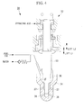
Fig. 1 is a schematic configuration view showing a fuel injection device for an internal combustion engine according to a first embodiment of the present invention. - {
Fig. 2 }
Fig. 2 shows a graphic chart illustrating a relationship between a cam lift amount of a cam shown inFig. 1 and a crank angle (cam angle). - {
Fig. 3 }
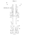
Fig. 3 is a schematic configuration view showing a fuel injection device for an internal combustion engine according to a second embodiment of the present invention. - {
Fig. 4 }
Fig. 4 is a schematic configuration view showing a fuel injection valve according to a third embodiment of the present invention, in which a main nozzle and a sub nozzle are closed. - {
Fig. 5 }
Fig. 5 is a schematic configuration view showing the fuel injection valve according to the third embodiment of the present invention, in which a mixture of fuel oil and water in a multilayered state or in an emulsion state is being injected. - {
Fig. 6 }
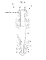
Fig. 6 is a schematic configuration view showing the fuel injection valve according to the third embodiment of the present invention, in which only the fuel oil is being injected. - {
Fig. 7 }
Fig. 7 is a schematic configuration view showing a fuel injection device for an internal combustion engine according to a fourth embodiment of the present invention. - {
Fig. 8 }
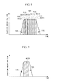
Fig. 8 is a view explaining a function of the fuel injection device for an internal combustion engine according to the present invention. - {
Fig. 9 }
Fig. 9 is a view explaining a function of the fuel injection device for an internal combustion engine according to the present invention. - A fuel injection device for an internal combustion engine according to the first embodiment of the present invention will be explained with reference to
Figs. 1 and2 .
Fig. 1 is a schematic configuration view showing a fuel injection device for an internal combustion engine according to the present embodiment.Fig. 2 shows a graphic chart illustrating the relationship between a cam lift amount of a cam shown inFig. 1 and a crank angle (cam angle).
It is to be noted that the fuel injection device for an internal combustion engine according to the present invention is configured to be mounted on an internal combustion engine (not shown) such as a large size diesel engine for a ship. - As shown in
Fig. 1 , afuel injection device 1 for an internal combustion engine according to the present embodiment is a fuel injection device capable of changing a fuel injection mode (operation mode) of a main engine and a generator, as disclosed inPTL 1 for example, from injection of fuel oil only to injection of a mixture of fuel oil and water in a multilayered state or in an emulsion state before going into an Emission Control Area from the outside of the Emission Control Area, and capable of changing the fuel injection mode (operation mode) of the main engine and the generator from injection of the mixture of fuel oil and water in a multilayered state or in an emulsion state to injection of the fuel oil only upon moving from the range of the Emission Control Area to the outside of the Emission Control Area. Thefuel injection device 1 includes onefuel injection pump 2 and at least one fuel injection valve (two in this embodiment) 3, so that a pair of them is placed for each cylinder. - In
Fig. 1 , there are shown adistributor 4, acheck valve 5, and a fuel/water feed pipe (high pressure pipe) 6. Configurations of thefuel injection pump 2, thefuel injection valve 3, thedistributor 4 and thecheck valve 5 are not particularly limited, and configurations of publicly known fuel injection pumps, fuel injection valves, distributors, and check valves may be used therefor. - Now, the
fuel injection pump 2 according to the present embodiment is a Bosch fuel injection pump including aplunger 7 and atappet 8 and is attached onto acam shaft 9 of each cylinder via a flange (not shown).
Acam 10 includes: a cam (first cam) for inside of ECA that lifts up theplunger 7 and thetappet 8 at a timing shown with a solid line inFig. 2 in the inside of an Emission Control Area; and a cam (second cam) for outside of ECA that lifts up theplunger 7 and thetappet 8 at a timing shown with a broken line inFig. 2 in the outside of the Emission Control Area. Thecam 10 is placed on acam shaft 9 side by side with a reversing cam. - The cam for inside of ECA is a cam, as shown in
Fig. 8 or 9 for example, which has a relationship between a cam lift amount and a crank angle (cam angle) that is suitable for injecting a mixture of fuel oil and water in a multilayered state or in an emulsion state. The cam for outside of ECA is a cam that lifts up theplunger 7 and thetappet 8 at a speed faster than that of the cam for inside of ECA. - According to the
fuel injection device 1 for an internal combustion engine in the present embodiment, when a mixture of fuel oil and an inert substance in a multilayered state or in an emulsion state is injected from thefuel injection valve 3 into a cylinder liner, theplunger 7 of thefuel injection pump 2 is lifted up by the cam for inside of ECA (first cam), whereas when only the fuel oil is injected from thefuel injection valve 3 into the cylinder liner, theplunger 7 of thefuel injection pump 2 is lifted up by the cam for outside of ECA (second cam) that lifts up theplunger 7 at a speed faster than that of the cam for inside of ECA.
As a consequence, it becomes possible to prevent decrease in fuel injection pressure, deterioration in combustibility, and degradation in performance of the internal combustion engine as well as to prevent increase in dust and black smoke. - A fuel injection device for an internal combustion engine according to the second embodiment of the present invention will be explained with reference to
Fig. 3 .
Fig. 3 is a schematic configuration view showing the fuel injection device for an internal combustion engine according to the present embodiment. - As shown in
Fig. 3 , afuel injection device 21 for an internal combustion engine according to the present embodiment is different from that of the first embodiment in that a cam for inside ofECA 22 is provided instead of thecam 10, a base end (one end) of abranch pipe 23 is connected to the intermediate position of a fuel/water feed pipe (high pressure pipe) 6 positioned between acheck valve 5 and adistributor 4 while a leading end (the other end) of thebranch pipe 23 is connected to anaccumulator 24. Since other component members are identical to those of the first embodiment described above, a description of these component members will be omitted herein.
It is to be noted that component members identical to those of the first embodiment described above are designated by identical reference signs to omit a description thereof. - A
control valve 25 is connected to an intermediate position thebranch pipe 23, thecontrol valve 25 being closed when a mixture of fuel oil and water in a multilayered state or in an emulsion state is injected from thefuel injection valve 3 and being opened when only the fuel oil is injected from thefuel injection valve 3. Thecontrol valve 25 is also opened and closed in response to a command signal from a controller (not shown) that determines (grasps) whether a fuel injection mode (operation mode) of a main engine and a generator is a mode of injecting a mixture of fuel oil and water in a multilayered state or in an emulsion state from thefuel injection valve 3 or it is a mode of injecting fuel oil only from thefuel injection valve 3. - According to the
fuel injection device 21 for an internal combustion engine in the present embodiment, when only the fuel oil is injected from thefuel injection valve 3 into a cylinder liner, thecontrol valve 25 is opened, so that injection pressure of the fuel oil injected from thefuel injection valve 3 into a cylinder is raised (increased).
As a consequence, it becomes possible to prevent decrease in fuel injection pressure, deterioration in combustibility, and degradation in performance of the internal combustion engine as well as to prevent increase in dust and black smoke. - A fuel injection device for an internal combustion engine according to the third embodiment of the present invention will be explained with reference to
Figs. 4 to 6 .
Fig. 4 is a schematic configuration view showing a fuel injection valve according to the present embodiment.Fig. 5 is a view showing a mixture of fuel oil and water in a multilayered state or in an emulsion being injected.Fig. 6 is a view showing only the fuel oil being injected. - As shown in
Figs. 4 to 6 , afuel injection device 31 for an internal combustion engine according to the present embodiment is different from that of the first embodiment described above in that a cam for inside of ECA 22 (seeFig. 3 ) is provided instead of thecam 10 and afuel injection valve 32 is provided instead of thefuel injection valve 3. Since other component members are identical to those of the first embodiment described above, a description of these component members will be omitted herein.
It is to be noted that component members identical to those of the first embodiment described above are designated by identical reference signs to omit a description thereof. - When the
plunger 7 and thetappet 8 are not lifted up by the cam for inside ofECA 22 and so the fuel pressure is not raised in thefuel injection valve 32, aneedle valve 33 sits onto asheet surface 35 of aninjection nozzle portion 34 as shown inFig. 4 so as to block inflow of a mixture of fuel oil and water in a multilayered state or in an emulsion state, or fuel oil, from anozzle chamber 36 to asub nozzle 37 and amain nozzle 38 and to block injection of the mixture of fuel oil and water in a multilayered state or in an emulsion state, or the fuel oil, from thesub nozzle 37 and themain nozzle 38.
When the fuel pressure is raised by theplunger 7 and thetappet 8 being lifted up by the cam for inside ofECA 22, and operating air is also fed to a top portion, theneedle valve 33 is raised (lifted) from thesheet surface 35 of theinjection nozzle portion 34 by a length of L1 + L2 as shown inFig. 5 so as to allow inflow of the mixture of fuel oil and water in a multilayered state or in an emulsion state from inside thenozzle chamber 36 to thesub nozzle 37 and themain nozzle 38 and to allow injection of the mixture of fuel oil and water in a multilayered state or in an emulsion state from thesub nozzle 37 and themain nozzle 38.
In this configuration, when the fuel pressure is raised by theplunger 7 and thetappet 8 being lifted up by the cam for inside ofECA 22, and operating air fed to the top portion is blocked, theneedle valve 33 is raised by a length of L1 from thesheet surface 35 of theinjection nozzle portion 34 as shown inFig. 6 so as to allow inflow of the fuel oil from inside thenozzle chamber 36 to thesub nozzle 37 and to allow injection of the fuel oil only from thesub nozzle 37. - According to the
fuel injection device 31 for an internal combustion engine in the present embodiment, when only the fuel oil is injected into the cylinder liner, themain nozzle 38 is closed so that the fuel oil is injected only from thesub nozzle 37.
As a consequence, it becomes possible to prevent decrease in fuel injection pressure, deterioration in combustibility, and degradation in performance of the internal combustion engine as well as to prevent increase in dust and black smoke. - A fuel injection device for an internal combustion engine according to the fourth embodiment of the present invention will be explained with reference to
Fig. 7 .
Fig. 7 is a schematic configuration view showing the fuel injection device for an internal combustion engine according to the present embodiment. - As shown in
Fig. 7 , afuel injection device 41 for an internal combustion engine according to the present embodiment is different from that of the first embodiment described above in that a cam for inside ofECA 22 is provided instead of thecam 10 and two fuel injection pumps 2 are provided. Since other component members are identical to those of the first embodiment described above, a description of these component members will be omitted herein.
It is to be noted that component members identical to those of the first embodiment described above are designated by identical reference signs to omit a description thereof. - The fuel injection pumps 2 according to the present embodiment are configured such that both the pumps are used when only fuel oil is injected from the
fuel injection valve 3, whereas when a mixture of fuel oil and water in a multilayered state or in an emulsion state is injected from thefuel injection valve 3, only one pump (left-side pump inFig. 7 in the present embodiment) is used. More specifically, when the mixture of fuel oil and water in a multilayered state or in an emulsion state is injected from thefuel injection valve 3, a rack position of a fuel rack (not shown) of the other fuel injection pump 2 (right-side pump inFig. 7 in the present embodiment) is set to "0 (zero)" and acontrol valve 43, which is connected to the intermediate position of a fuel/water feed pipe 42 that feeds the mixture of fuel oil and water in a multilayered state or in an emulsion state to the otherfuel injection pump 2, is closed. The rack position of the fuel rack of the otherfuel injection pump 2 and thecontrol valve 43 are operated and opened/closed in response to command signals from a controller (not shown) that determines (grasps) whether a fuel injection mode (operation mode) of a main engine and a generator is a mode of injecting the mixture of fuel oil and water in a multilayered state or in an emulsion state from thefuel injection valve 3 or it is a mode of injecting fuel oil only from thefuel injection valve 3. - According to the
fuel injection device 41 for an internal combustion engine in the present embodiment, when only the fuel oil is injected into a cylinder liner, the pressurized fuel oil is fed from two fuel injection pumps 2 to thefuel injection valve 3.
As a consequence, it becomes possible to prevent decrease in fuel injection pressure, deterioration in combustibility, and degradation in performance of the internal combustion engine as well as to prevent increase in dust and black smoke. - It should be understood that the present invention is not limited to the embodiments described above and appropriate deformations and modifications are possible where necessary.
For example, although the foregoing embodiments have been described with twofuel injection valves 3 being provided for everyfuel injection pump 2 as a specific example, three or fourfuel injection valves 3 may be provided for everyfuel injection pump 2. The present invention is not limited by the number of thefuel injection valves 3.
Moreover, in the foregoing embodiments, other inert substances may be used in place of water. - Further, at least one
fuel injection valve 3 for injecting fuel oil only and at least onefuel injection valve 3 for injecting a mixture of fuel oil and water in a multilayered state or in an emulsion state may be configured to be mounted on each cylinder, so that the fuel injection valves may be switched in accordance with the fuel injection mode (operation mode) of the main engine and the generator.
Furthermore, the combustion engine itself may be constituted as an electronically-controlled engine and be controlled so as to raise (increase) injection pressure of fuel oil when only the fuel oil is injected from thefuel injection valve 3. -
- 1
- Fuel injection device for an internal combustion engine
- 2
- Fuel injection pump
- 3
- Fuel injection valve
- 6
- Fuel/water feed pipe
- 7
- Plunger
- 10
- Cam
- 21
- Fuel injection device for an internal combustion engine
- 22
- Cam for inside of ECA (first cam)
- 23
- Branch pipe
- 24
- Accumulator
- 25
- Control valve
- 31
- Fuel injection device for an internal combustion engine
- 32
- Fuel injection valve
- 33
- Needle valve
- 37
- Sub nozzle
- 38
- Main nozzle
- 41
- Fuel injection device for an internal combustion engine
- 42
- Fuel/water feed pipe
- 43
- Control valve
Claims (6)
- A fuel injection device for an internal combustion engine, capable of selectively injecting, from a fuel injection valve, a mixture of fuel oil and an inert substance in a multilayered state or in an emulsion state, or fuel oil only, wherein
a cam for lifting up a plunger of a fuel injection pump that pressurizes and feeds the mixture of fuel oil and the inert substance in a multilayered state or in an emulsion state, or the fuel oil to the fuel injection valve includes:a first cam for use in lifting up the mixture of fuel oil and the inert substance in a multilayered state or in an emulsion state; anda second cam for use in lifting up the fuel oil only. - A fuel injection device for an internal combustion engine, capable of selectively injecting, from a fuel injection valve, a mixture of fuel oil and an inert substance in a multilayered state or in an emulsion state, or fuel oil only, wherein
a fuel injection pump that pressurizes and feeds the mixture of fuel oil and the inert substance in a multilayered state or in an emulsion state, or the fuel oil to the fuel injection valve, is linked to the fuel injection valve through a fuel/water feed pipe,
a base end of a branch pipe is connected to an intermediate position the fuel/water feed pipe, while a leading end of the branch pipe is connected to an accumulator, and
a control valve is connected to an intermediate position the branch pipe, the control valve being closed when the mixture of fuel oil and the inert substance in a multilayered state or in an emulsion state is injected from the fuel injection valve and being opened when only the fuel oil is injected from the fuel injection valve. - A fuel injection device for an internal combustion engine, capable of selectively injecting, from a fuel injection valve, a mixture of fuel oil and an inert substance in a multilayered state or in an emulsion state, or fuel oil only, wherein
the fuel injection valve includes:main and sub nozzles; anda needle valve that is lifted in two stages corresponding to pressure of control air to be fed, so that in a low lift state, the sub nozzle is opened to inject the fuel oil, while in a high lift state, both the main nozzle and the sub nozzle are opened to inject the mixture of fuel oil and the inert substance in a multilayered state or in an emulsion state. - A fuel injection device for an internal combustion engine, capable of selectively injecting, from a fuel injection valve, a mixture of fuel oil and an inert substance in a multilayered state or in an emulsion state, or fuel oil only, wherein
at least two fuel injection pumps that pressurize and feed the mixture of fuel oil and the inert substance in a multilayered state or in an emulsion state, or the fuel oil to the fuel injection valve,
a fuel/water feed pipe that feeds the mixture of fuel oil and the inert substance in a multilayered state or in an emulsion state, or the fuel oil to these fuel injection pumps, and
a control valve that is connected to an intermediate position the fuel/water feed pipe are connected to each other, the control valve being closed when the mixture of fuel oil and the inert substance in a multilayered state or in an emulsion state is injected from the fuel injection valve and being opened when only the fuel oil is injected from the fuel injection valve. - An internal combustion engine comprising a fuel injection device for an internal combustion engine according to any one of claims 1 to 4.
- A ship comprising an internal combustion engine according to claim 5.
Applications Claiming Priority (2)
| Application Number | Priority Date | Filing Date | Title |
|---|---|---|---|
| JP2010249807A JP2012102631A (en) | 2010-11-08 | 2010-11-08 | Fuel injection device for internal combustion engine |
| PCT/JP2011/075217 WO2012063686A1 (en) | 2010-11-08 | 2011-11-01 | Fuel injection device for internal combustion engine |
Publications (1)
| Publication Number | Publication Date |
|---|---|
| EP2639439A1 true EP2639439A1 (en) | 2013-09-18 |
Family
ID=46050836
Family Applications (1)
| Application Number | Title | Priority Date | Filing Date |
|---|---|---|---|
| EP11839282.8A Withdrawn EP2639439A1 (en) | 2010-11-08 | 2011-11-01 | Fuel injection device for internal combustion engine |
Country Status (5)
| Country | Link |
|---|---|
| EP (1) | EP2639439A1 (en) |
| JP (1) | JP2012102631A (en) |
| KR (2) | KR20130021447A (en) |
| CN (1) | CN103732901A (en) |
| WO (1) | WO2012063686A1 (en) |
Families Citing this family (3)
| Publication number | Priority date | Publication date | Assignee | Title |
|---|---|---|---|---|
| DK178072B1 (en) * | 2014-01-06 | 2015-04-27 | Man Diesel & Turbo Deutschland | A method of operating an internal combustion engine |
| JP7465634B2 (en) * | 2019-06-14 | 2024-04-11 | 株式会社ジャパンエンジンコーポレーション | Marine Diesel Engines |
| CN119195951B (en) * | 2024-09-27 | 2025-10-03 | 中国船舶集团有限公司第七一一研究所 | Dual fuel injection system, injection unit pump, engine, and injection method |
Family Cites Families (10)
| Publication number | Priority date | Publication date | Assignee | Title |
|---|---|---|---|---|
| JPH0311148A (en) * | 1989-06-09 | 1991-01-18 | Mitsubishi Heavy Ind Ltd | Two fluid injection valve |
| CH683515A5 (en) | 1990-10-26 | 1994-03-31 | Ehrensperger C Ag | An apparatus for dispensing a consisting of at least two component mixture. |
| JPH06101590A (en) * | 1992-09-21 | 1994-04-12 | Mitsubishi Heavy Ind Ltd | Binary fluid injection valve |
| JP3191581B2 (en) * | 1994-11-15 | 2001-07-23 | 三菱自動車工業株式会社 | Water injection valve and diesel engine with water injection valve |
| JP3615260B2 (en) | 1995-03-07 | 2005-02-02 | 川崎重工業株式会社 | Fuel supply system for diesel engine |
| EP0760425B1 (en) * | 1995-08-30 | 2000-11-15 | Robert Bosch Gmbh | Injection device |
| JPH1130165A (en) * | 1997-07-09 | 1999-02-02 | Mitsubishi Heavy Ind Ltd | Fuel injection device |
| DE19747268A1 (en) * | 1997-10-25 | 1999-04-29 | Bosch Gmbh Robert | Dual fluid injection system for internal combustion engine |
| JP4208349B2 (en) * | 1999-06-29 | 2009-01-14 | ナブテスコ株式会社 | Emulsion fuel supply system |
| JP4508411B2 (en) * | 2000-12-28 | 2010-07-21 | 三菱重工業株式会社 | Fuel / water injection internal combustion engine |
-
2010
- 2010-11-08 JP JP2010249807A patent/JP2012102631A/en active Pending
-
2011
- 2011-11-01 CN CN201180036316.0A patent/CN103732901A/en active Pending
- 2011-11-01 WO PCT/JP2011/075217 patent/WO2012063686A1/en not_active Ceased
- 2011-11-01 KR KR1020137001173A patent/KR20130021447A/en not_active Ceased
- 2011-11-01 KR KR1020147021028A patent/KR20140098868A/en not_active Ceased
- 2011-11-01 EP EP11839282.8A patent/EP2639439A1/en not_active Withdrawn
Non-Patent Citations (1)
| Title |
|---|
| See references of WO2012063686A1 * |
Also Published As
| Publication number | Publication date |
|---|---|
| KR20130021447A (en) | 2013-03-05 |
| KR20140098868A (en) | 2014-08-08 |
| JP2012102631A (en) | 2012-05-31 |
| WO2012063686A1 (en) | 2012-05-18 |
| CN103732901A (en) | 2014-04-16 |
Similar Documents
| Publication | Publication Date | Title |
|---|---|---|
| EP2123890A1 (en) | A method and system for controlling operating pressure in a common-rail fuel injection system, particularly for a diesel engine | |
| KR101564867B1 (en) | Dual-fuel diesel engine and method for operating same | |
| US20090066337A1 (en) | Method for determining valve degradation | |
| EP1929142B1 (en) | Method for operating an internal combustion engine | |
| US20200232403A1 (en) | Methods and system for skip-firing of an engine | |
| EP1853814B1 (en) | Fuel supply apparatus for vehicle | |
| KR101978012B1 (en) | Fuel injection system | |
| CN107923337A (en) | For controlling the control method and fuel injection system of fuel injection system | |
| EP1707785B1 (en) | Control apparatus for diesel-type internal combustion engine | |
| EP2634414B1 (en) | Fuel-injection valve for an internal combustion engine | |
| WO2012063686A1 (en) | Fuel injection device for internal combustion engine | |
| US9739209B2 (en) | Method for operating a fuel injection system of an internal combustion engine | |
| EP2705239B1 (en) | Fuel injection unit and system | |
| WO2015022445A1 (en) | Method for injecting liquid fuel and fuel injection system | |
| CN108779719B (en) | Control device for multi-cylinder engine | |
| JP4306117B2 (en) | Accumulated fuel injection system | |
| JP6323799B2 (en) | Multi-cylinder engine controller | |
| JP4903762B2 (en) | Fuel injection device | |
| EP2565432B1 (en) | Fuel injection timing control for a large reciprocating piston combustion engine | |
| JP6288610B2 (en) | Engine control device | |
| JP6278342B2 (en) | Multi-cylinder engine controller | |
| JP6395117B2 (en) | Engine control device | |
| JP2006336500A (en) | Control device for internal combustion engine | |
| JP2001153001A (en) | Fuel injection device for internal combustion engine | |
| JPH06346812A (en) | Fuel and water injection device |
Legal Events
| Date | Code | Title | Description |
|---|---|---|---|
| PUAI | Public reference made under article 153(3) epc to a published international application that has entered the european phase |
Free format text: ORIGINAL CODE: 0009012 |
|
| 17P | Request for examination filed |
Effective date: 20130125 |
|
| AK | Designated contracting states |
Kind code of ref document: A1 Designated state(s): AL AT BE BG CH CY CZ DE DK EE ES FI FR GB GR HR HU IE IS IT LI LT LU LV MC MK MT NL NO PL PT RO RS SE SI SK SM TR |
|
| DAX | Request for extension of the european patent (deleted) | ||
| STAA | Information on the status of an ep patent application or granted ep patent |
Free format text: STATUS: THE APPLICATION HAS BEEN WITHDRAWN |
|
| 18W | Application withdrawn |
Effective date: 20150116 |
|
| RIC1 | Information provided on ipc code assigned before grant |
Ipc: F02M 43/04 20060101ALI20150119BHEP Ipc: F02B 47/04 20060101ALI20150119BHEP Ipc: F02M 25/022 20060101AFI20150119BHEP Ipc: F02M 43/02 20060101ALI20150119BHEP |