EP2638552B1 - Interrupteur avec actionneur pivotant - Google Patents
Interrupteur avec actionneur pivotant Download PDFInfo
- Publication number
- EP2638552B1 EP2638552B1 EP11840327.8A EP11840327A EP2638552B1 EP 2638552 B1 EP2638552 B1 EP 2638552B1 EP 11840327 A EP11840327 A EP 11840327A EP 2638552 B1 EP2638552 B1 EP 2638552B1
- Authority
- EP
- European Patent Office
- Prior art keywords
- actuator
- switch
- axis
- conductor
- rotary
- Prior art date
- Legal status (The legal status is an assumption and is not a legal conclusion. Google has not performed a legal analysis and makes no representation as to the accuracy of the status listed.)
- Active
Links
Images


Classifications
-
- H—ELECTRICITY
- H01—ELECTRIC ELEMENTS
- H01H—ELECTRIC SWITCHES; RELAYS; SELECTORS; EMERGENCY PROTECTIVE DEVICES
- H01H19/00—Switches operated by an operating part which is rotatable about a longitudinal axis thereof and which is acted upon directly by a solid body external to the switch, e.g. by a hand
- H01H19/46—Switches operated by an operating part which is rotatable about a longitudinal axis thereof and which is acted upon directly by a solid body external to the switch, e.g. by a hand the operating part having three operative positions, e.g. off/star/delta
-
- H—ELECTRICITY
- H01—ELECTRIC ELEMENTS
- H01H—ELECTRIC SWITCHES; RELAYS; SELECTORS; EMERGENCY PROTECTIVE DEVICES
- H01H23/00—Tumbler or rocker switches, i.e. switches characterised by being operated by rocking an operating member in the form of a rocker button
- H01H23/02—Details
- H01H23/12—Movable parts; Contacts mounted thereon
- H01H23/16—Driving mechanisms
- H01H23/162—Driving mechanisms incorporating links interconnecting tumbler and contact arm
-
- H—ELECTRICITY
- H01—ELECTRIC ELEMENTS
- H01H—ELECTRIC SWITCHES; RELAYS; SELECTORS; EMERGENCY PROTECTIVE DEVICES
- H01H3/00—Mechanisms for operating contacts
- H01H3/32—Driving mechanisms, i.e. for transmitting driving force to the contacts
- H01H3/42—Driving mechanisms, i.e. for transmitting driving force to the contacts using cam or eccentric
-
- H—ELECTRICITY
- H01—ELECTRIC ELEMENTS
- H01H—ELECTRIC SWITCHES; RELAYS; SELECTORS; EMERGENCY PROTECTIVE DEVICES
- H01H23/00—Tumbler or rocker switches, i.e. switches characterised by being operated by rocking an operating member in the form of a rocker button
- H01H23/02—Details
- H01H23/12—Movable parts; Contacts mounted thereon
- H01H23/16—Driving mechanisms
- H01H23/20—Driving mechanisms having snap action
- H01H23/205—Driving mechanisms having snap action using a compression spring between tumbler and an articulated contact plate
Definitions
- the present invention relates generally to the field of electrical switches, and more specifically, relates to a switch employing a pivotal movement to connect and disconnect multiple terminals.
- the invention is directed toward a switch for electrically connecting and disconnecting electrical terminals as defined in claim 1.
- the switch uses a pivoting action of an actuator, which actuates a conductor to connect and disconnect the electrical terminals.
- a rotary switch having a body, a rotary knob attached to the body, and at least two terminals attached to the body.
- An actuator is pivotably mounted within the body and operably connected to the rotary knob, the actuator pivoting upon a rotation of the rotary knob.
- a conductor is pivotably mounted in the body and is in communication with the actuator and is adapted to connect or disconnect the at least two terminals when the actuator is pivotably moved.
- a plunger is movably mounted to the actuator and a biasing member is in operable communication with the actuator and the plunger, the biasing member biasing the plunger away from the actuator.
- a cam is located between the rotary knob the said actuator and is eccentric to a rotational axis of the rotary knob, the cam translating a rotational movement of the rotary knob into a pivotable movement of the actuator.
- a roller is attached to the plunger, the roller rolling along the conductor to connect or disconnect the at least two terminals when the actuator is pivoted.
- the conductor is in slideable communication with the actuator.
- the biasing member is a spring.
- at least one detent in the conductor is adapted to fit the roller.
- a plurality of detents in the body are located adjacent to the rotary knob and are adapted to fit a nose of the rotary knob.
- a biasing member in the biases the nose in an extended position inside one of the plurality of detents.
- the rotary pivots about a first axis
- the actuator pivots about a second axis, the second axis being different than the first axis
- the conductor pivots about a third axis, the third axis being different than the first axis and the second axis.
- the second axis and the third axis are parallel.
- the first axis is orthogonal to the second axis and the third axis.
- a switch having a body and at least two terminals attached to the body.
- An actuator is pivotably mounted within the body.
- a conductor is pivotably mounted in the body and is in communication with the actuator and is adapted to connect or disconnect the at least two terminals when the actuator is pivotably moved.
- a plunger is movably mounted to the actuator and a biasing member is in operable communication with the actuator and the plunger and biases the plunger away from said actuator.
- a roller is attached to the plunger and rolls along the conductor to connect or disconnect the at least two terminals when the actuator is pivoted.
- the conductor is in slideable communication with the actuator.
- the switch is a rotary switch having a rotary knob attached to the body and a cam located between the rotary knob and the actuator and eccentric to a rotational axis of the rotary knob, the cam translating a rotational movement of the rotary knob into a pivotable movement of the actuator.
- the switch is a rocker switch, having a rocker attached to the body and the actuator, the rocker pivoting the actuator on actuation of the rocker.
- the biasing member is a spring.
- at least one detent in the conductor is adapted to fit the roller.
- a plurality of detents in the body are located adjacent to the rotary knob and are adapted to fit a nose of the rotary knob.
- a biasing member is in the nose and biases the nose in an extended position inside one of the plurality of detents.
- the actuator pivots about a second axis
- the second axis being different than the first axis
- the conductor pivots about a third axis the third axis being different than the first axis and the second axis.
- the second axis and the third axis are parallel.
- the first axis is orthogonal to the second axis and the third axis.
- a rotary switch having a body, a rotary knob attached to the body, and at least two terminals attached to the body.
- An actuator is pivotably mounted within the body and is operably connected to the rotary knob through a cam, the cam translating a rotational movement of the rotary knob into a pivotable movement of the actuator and being eccentric to a rotational axis of the rotary knob.
- a plunger is movably mounted to the actuator.
- a spring is in operable communication with the actuator and the plunger and biases the plunger away from the actuator.
- a conductor is pivotably mounted within the body and is in rolling communication with the actuator through a roller. The conductor has least one detent and is adapted to connect or disconnect the at least two terminals when the actuator is pivotably moved.
- the roller is attached to the plunger and the roller rolls along the conductor to connect or disconnect the at least two terminals when the actuator is pivoted.
- a plurality of detents in the body are located adjacent to the rotary knob and are adapted to fit a nose of the rotary knob.
- a biasing member in said nose biases the nose in an extended position inside one of the plurality of detents.
- the rotary knob pivots about a first axis
- the actuator pivots about a second axis, the second axis being different than the first axis
- the conductor pivots about a third axis, the third axis being different than the first axis and the second axis.
- the second axis and the third axis are parallel.
- the first axis is orthogonal to the second axis and the third axis.
- One exemplary embodiment of the present invention is related to a rotary switch. Specifically, the rotational movement of the rotary switch is translated into a pivoting movement of an actuator in order to connect and disconnect multiple terminals.
- Another exemplary embodiment employs a rocker switch to pivot the actuator in order to connect and disconnect multiple terminals.
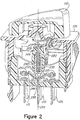
- a perspective view of a rotary switch 100 is shown.
- the rotary switch 100 includes a body 105 and a rotary, shown as a knob 110, rotationally mounted to the body 105.
- Rotary switch 100 has a plurality of terminals such as terminals 115, 120, and 125. It should be noted that while rotary switch 100 is shown having six terminals, rotary switch 100 can be modified to operate with greater than or less than six terminals.
- Knob 110 has a portion 205, as a post, a cam, or the like that is eccentric to a rotational axis 210 of the rotary switch 100.
- Terminals 115, 120, and 125 are mounted to the body 105 and a conductor 215 is configured to be movable from at least one position wherein the conductor 215 is electrically connected to both terminals 115 and 120, a second position wherein the conductor 215 is electrically connected to both terminals 120 and 125, and a third position wherein the conductor 215 is electrically disconnected from terminals 115 and 125.
- the rotary switch 100 further has an actuator 220 that is pivotally mounted within the body 105 at one end 225 as seen in Figure 4 , and is movably engaged with the conductor 215 at the other end 230. Rotational movement of the rotary 105 causes the eccentric portion 205 to rotate about the axis 210. Engagement of the eccentric portion 205 with the actuator 220 causes the actuator 220 to pivot.
- Rotary switch 100 has a plunger 235 that is movably mounted within a recess in actuator 220 along with a biasing member 240, shown as a compression spring, biasing the plunger 235 in a direction away from the actuator 220.
- the spring 240 assures that the plunger 235 remains in contact with the conductor 215 throughout the pivotal travel of the actuator 220. It should be noted that plunger 235 and spring 240 need not be present and the flexing of the conductor 215 may be used to assure continuous contact between the actuator 220 and the conductor 215.
- Rotary switch 100 may also include a roller 255 that is rotationally mounted to the plunger 235. The roller 255 rolls relative to the conductor 215 to reduce frictional engagement between the plunger 235 and the conductor 215.
- conductor 215 moves relative to the body 105 in a rocking or seesaw type motion in response to the actuator 220 pivotally moving relative to the body 105.
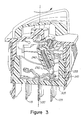
- the terminals 115, 120, and 125 are electrically connected to one another through the conductor 215 when the actuator 220 is pivoted.
- conductor 120 is electrically connected to conductor 125 when actuator 220 is pivoted to the right.
- neither terminal 115 nor terminal 125 is electrically connected to terminal 120.
- additional terminals could be electrically connected and disconnected via the pivotal movement of the actuator 220 through the movement of the conductor 215, or through movement of an additional conductor added to the assembly and moved by the actuator 220 in a similar manner to the movement of the conductor 215.
- a second plunger 305 can be actuated to connect additional terminals.
- the shape of the surface 245 of the conductor 215 and the rocking movement of the conductor 215 may be configured such that the plunger 235 is at a further distance from the actuator 220 when the actuator 220 is pivoted to the selected positions within its travel. In so doing, the spring 240 will generate a bias on the conductor 215.
- Conductor 215 is capable of being flexed in a downward direction forcing end 310 of conductor 215 to contact the top portion 305 of terminal 125. This creates an electrical connection between terminals 120 and 125.
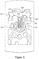
- Rotary switch 100 is capable of being rotated into multiple positions some of which are configured to make electrical contact between the terminals 115, 120, and 125, and some of which are configured to maintain the rotary switch 105 in a position where there is no electrical contact between any of the terminals.
- This pivotal biasing of the actuator 220 will also generate a bias on the knob 110.
- This bias on the knob 110 will preferentially maintain the knob 110 at specific positions within its rotational travel.
- conductor 215 may have detents 250, on either side of the conductor, shaped to allow roller 255 to fit inside, preventing knob 110 from rotating back into a position of no electrical contact between the conductors.
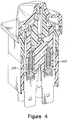
- Rotary switch 100 may have detents 505 having a cam surface 410 thereof that is substantially fixed relative to the body 105.
- a nose 520 of a follower 515 is made to move or flex as the follower 515 is rotated.
- the nose 520 is a separate steel ball 525 and is able to rotate as it moves along the cam surface 510.
- a biasing member 530 shown as a compression spring, biases the nose 520 toward the cam surface 510 to thereby assure continuous contact therewith and provide the rotational detent positioning effect desired by the detents 510.
- a corresponding pivoting movement is created in actuator 220.
- a rotation of knob 110 by 18 degrees may correspond to a pivot of 60 degrees of actuator 220.
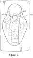
- Detents 505 prevent knob 110 from being in a non-rotated state, or partially open state, such as that shown in Figure 5 . Detents 505 will always move knob 110 to the desired state. Detents 505 also assist in providing a smooth and crisp tactile feel to the rotation of knob 110 such that the person who actuates the switch is given direct feedback as to whether knob 110 has been rotated and the terminals have been electrically connected or disconnected. It should be noted that while rotary switch 100 is shown as having two detents for two rotational positions, rotary switch 100 may have any number of detents corresponding to any number of rotational positions including more than two detents.
- Rotary switch 600 may have a plurality of detents 605.
- the plurality of detents 605 provide additional biasing of the rotary 610 to selected rotational positions.
- Detents 605 may include a cam surface 610 disposed on the body 105, and a follower 615 configured to follow the cam surface 610.
- the cam surface 610 may be flexible relative to the body 105 to allow a nose 620 on the follower 615 that moves along a circular arc, to deflect the cam surface 610 as the follower rotates relative thereto.
- cam surface 610 provides a load between the nose 620 and the cam surface 610 needed to provide the rotational detent positioning effect desired by the detents 605; nose 620 being slideably engaged with the cam surface 610. It should be noted that while rotary switch 600 is shown as having three detents for three rotational positions, rotary switch 600 may have any number of detents corresponding to any number of rotational positions including more than three detents.
- Rocker switch 700 has a rocker 705 attached to a housing 710 that electrically connects the terminals 715, 720, and 725.
- a conductor 730, a plunger 735, a biasing member 740 and a roller 745 of the rocker 700 operate in a manner similar to the components of rotary switch 100 above.
- Mounting features such as a flange 750, and ratchet teeth 755 on flex tabs 760, can all be identically dimensioned between the rocker switch 700 and the rotary switch 100 above, thereby allowing either switch to be mounted in a particular application. This flexibility would allow a customer to customize applications without having to alter the mounting configurations, or the harness that controls the electrical loads. This commonality of components also provides monetary savings to switch manufacturers through reduced component tooling and assembly equipment.
- plunger 735 and roller 745 When rocker 705 is depressed, either on the left side or the right side of the rocker, actuator 760 is pivoted, causing plunger 735 and roller 745 to move in either the left or right direction. The movement of plunger 735 and roller 745, in conjunction with biasing member 740, results in an electrical contact either between terminals 715 and 720, or between terminals 725 and 720. To cease electrical contact, the user depresses the side of the rocker opposite to the side depressed to electrically connect the terminals.
Landscapes
- Rotary Switch, Piano Key Switch, And Lever Switch (AREA)
- Switches With Compound Operations (AREA)
Claims (10)
- Interrupteur comprenant :un corps (105, 710) ;au moins deux bornes (115, 120, 125, 715, 720, 725) attachées audit corps (105, 705);un actionneur (220, 760) monté de manière pivotante dans ledit corps (105, 710) ; un piston-plongeur (235, 735) monté de manière mobile sur ledit actionneur (220, 760) et un élément de sollicitation (240, 740) en communication fonctionnelle avec ledit actionneur (220, 760) et ledit piston-plongeur (235, 735), ledit élément de sollicitation (240, 740) sollicitant ledit piston-plongeur (235, 735) loin dudit actionneur (220, 760) ;un conducteur (215, 730) monté de manière pivotante dans ledit corps (105, 710) et en communication avec ledit actionneur (220, 760), ledit conducteur (215, 730) étant adapté pour connecter ou déconnecter lesdites au moins deux bornes (115, 120, 125, 715, 720, 725) quand ledit actionneur (220, 760) est déplacé de manière pivotante ;un rouleau (255, 745) attaché audit piston-plongeur (235, 735), ledit rouleau (255, 745) roulant le long dudit conducteur (215, 730) pour connecter ou déconnecter lesdites au moins deux bornes (115, 120, 125, 715, 720, 725) quand ledit actionneur (220, 760)) est pivoté ;caractérisé pardes crans (250) dans le conducteur (215, 730), de chaque côté du conducteur (215, 730), façonnés pour permettre au rouleau (255, 745) de s'insérer dans ceux-ci.
- Interrupteur selon la revendication 1, dans lequel ledit conducteur (215, 730) est en communication coulissante avec ledit actionneur (220, 760).
- Interrupteur selon la revendication 1, dans lequel ledit interrupteur est un interrupteur rotatif (100), et dans lequel ledit interrupteur rotatif (100) comprend en outre un bouton rotatif (110) attaché audit corps (105) et une came entre ledit bouton rotatif (110) et ledit actionneur (220) et excentrique par rapport à un axe de rotation dudit bouton rotatif (110), ladite came traduisant un déplacement rotatif dudit bouton rotatif (110) en un déplacement pivotant dudit actionneur (220).
- Interrupteur selon la revendication 1, dans lequel ledit interrupteur est un interrupteur à bascule (700), et dans lequel ledit interrupteur à bascule (700) comprend en outre une bascule (705) attachée audit corps (710) et audit actionneur (760), ladite bascule (705) faisant pivoter ledit actionneur (760) lors de l'actionnement de ladite bascule (705).
- Interrupteur selon la revendication 1, dans lequel ledit élément de sollicitation (240, 740) est un ressort (240).
- Interrupteur selon la revendication 3, comprenant en outre une pluralité de crans (250) dans ledit corps (105) situés de manière adjacente audit bouton rotatif (110) et adaptés pour accueillir un nez dudit bouton rotatif (110).
- Interrupteur selon la revendication 6, comprenant en outre un élément de sollicitation (240) dans ledit nez, ledit élément de sollicitation (240) sollicitant ledit nez dans une position étendue à l'intérieur d'un de ladite pluralité de crans.
- Interrupteur selon la revendication 1, dans lequel ledit interrupteur est un interrupteur rotatif (100), et dans lequel ledit interrupteur rotatif (100) comprend en outre un bouton rotatif (110) attaché audit corps (105), ledit bouton rotatif (110) pivote autour d'un premier axe, ledit actionneur (220) pivote autour d'un deuxième axe, ledit deuxième axe étant différent dudit premier axe, et ledit conducteur (215) pivote autour d'un troisième axe, ledit troisième axe étant différent dudit premier axe et dudit deuxième axe.
- Interrupteur selon la revendication 8, dans lequel ledit deuxième axe et ledit troisième axe sont parallèles.
- Interrupteur selon la revendication 9, dans lequel ledit premier axe est orthogonal audit deuxième axe et audit troisième axe.
Applications Claiming Priority (2)
| Application Number | Priority Date | Filing Date | Title |
|---|---|---|---|
| US41312410P | 2010-11-12 | 2010-11-12 | |
| PCT/US2011/060563 WO2012065159A1 (fr) | 2010-11-12 | 2011-11-14 | Interrupteur avec actionneur pivotant |
Publications (3)
| Publication Number | Publication Date |
|---|---|
| EP2638552A1 EP2638552A1 (fr) | 2013-09-18 |
| EP2638552A4 EP2638552A4 (fr) | 2016-11-02 |
| EP2638552B1 true EP2638552B1 (fr) | 2019-01-02 |
Family
ID=46046814
Family Applications (1)
| Application Number | Title | Priority Date | Filing Date |
|---|---|---|---|
| EP11840327.8A Active EP2638552B1 (fr) | 2010-11-12 | 2011-11-14 | Interrupteur avec actionneur pivotant |
Country Status (5)
| Country | Link |
|---|---|
| US (1) | US8642903B2 (fr) |
| EP (1) | EP2638552B1 (fr) |
| CN (1) | CN103250220B (fr) |
| CA (1) | CA2819363C (fr) |
| WO (1) | WO2012065159A1 (fr) |
Families Citing this family (10)
| Publication number | Priority date | Publication date | Assignee | Title |
|---|---|---|---|---|
| WO2014138526A1 (fr) * | 2013-03-07 | 2014-09-12 | Carling Technologies, Inc. | Commutateur à faible courant |
| US9484163B2 (en) | 2014-02-06 | 2016-11-01 | Eaton Corporation | Disconnect operating handles suitable for circuit breakers and related bucket assemblies |
| US9496101B2 (en) | 2014-02-06 | 2016-11-15 | Eaton Corporation | Disconnect operating handles suitable for circuit breakers and related bucket assemblies and handle interlocks |
| USD765045S1 (en) | 2014-03-24 | 2016-08-30 | Eaton Corporation | Switch handle for circuit breakers |
| USD750577S1 (en) * | 2014-03-24 | 2016-03-01 | Eaton Corporation | Switch handle for circuit breakers |
| USD751516S1 (en) | 2014-03-24 | 2016-03-15 | Eaton Corporation | Switch handle for circuit breakers |
| USD762593S1 (en) | 2014-03-24 | 2016-08-02 | Eaton Corporation | Switch handle for circuit breakers |
| US11189447B2 (en) * | 2014-03-28 | 2021-11-30 | Yaowu Hua | Time switch of controllable time adjustment |
| US9519349B2 (en) * | 2014-10-30 | 2016-12-13 | Industrial Smoke & Mirrors, Inc. | Touch screen interface device |
| USD817899S1 (en) * | 2016-06-02 | 2018-05-15 | Shin Chin Industrial Co., Ltd. | Portion of a switch |
Family Cites Families (14)
| Publication number | Priority date | Publication date | Assignee | Title |
|---|---|---|---|---|
| US3312800A (en) * | 1965-12-30 | 1967-04-04 | Texas Instruments Inc | Electrical switch employing improved contact break mechanism |
| DE2302452C3 (de) * | 1973-01-18 | 1981-10-15 | Ebe Elektro-Bau-Elemente Gmbh, 7022 Leinfelden-Echterdingen | Rastwerk für einen Stufendrehschalter |
| DE2948860A1 (de) | 1979-12-05 | 1981-06-11 | Petz Electro, Schmitten | Drehschalter, insbesondere zum einbau in rasterfeldoeffnungen vonschalttafelrasterfeldern |
| US4748297A (en) | 1986-07-11 | 1988-05-31 | Carlingswitch, Inc. | Rotary switch |
| US5045648A (en) * | 1990-03-23 | 1991-09-03 | Eaton Corporation | Locking rocker switch |
| US5186316A (en) * | 1990-09-14 | 1993-02-16 | Lee Craft Manufacturing Co., Inc. | Stable-on push-push electrical switch |
| ES2122201T3 (es) * | 1993-02-16 | 1998-12-16 | Schneider Electric Sa | Dispositivo de mando rotativo de un disyuntor. |
| JP3067588B2 (ja) * | 1995-05-08 | 2000-07-17 | 住友電装株式会社 | ブレーカスイッチ |
| US5725087A (en) * | 1996-10-07 | 1998-03-10 | Carlingswitch, Inc. | Rotary switch that converts to rotary action, a toggle style switching mechanism |
| US6069545A (en) * | 1999-01-08 | 2000-05-30 | Duraswitch Industries, Inc. | Magnetically actuated pushbutton switch |
| US6600122B1 (en) * | 2001-11-05 | 2003-07-29 | Reliance Controls Corporation | Centering arrangement for a movable contact member in a rocker-type switch |
| JP2004022301A (ja) | 2002-06-14 | 2004-01-22 | Tokai Rika Co Ltd | 一方向ロータリスイッチ |
| TW560691U (en) * | 2002-09-23 | 2003-11-01 | Atom Technology Inc | Rolling-type pressing head structure of switch |
| US6930269B1 (en) * | 2004-06-28 | 2005-08-16 | Eaton Corporation | Quiet, medium current rocker switch |
-
2011
- 2011-11-14 EP EP11840327.8A patent/EP2638552B1/fr active Active
- 2011-11-14 CA CA2819363A patent/CA2819363C/fr active Active
- 2011-11-14 CN CN201180058968.4A patent/CN103250220B/zh active Active
- 2011-11-14 US US13/296,013 patent/US8642903B2/en active Active
- 2011-11-14 WO PCT/US2011/060563 patent/WO2012065159A1/fr not_active Ceased
Non-Patent Citations (1)
| Title |
|---|
| None * |
Also Published As
| Publication number | Publication date |
|---|---|
| EP2638552A4 (fr) | 2016-11-02 |
| US8642903B2 (en) | 2014-02-04 |
| WO2012065159A1 (fr) | 2012-05-18 |
| US20120118713A1 (en) | 2012-05-17 |
| CN103250220A (zh) | 2013-08-14 |
| CA2819363A1 (fr) | 2012-05-18 |
| CN103250220B (zh) | 2016-01-20 |
| CA2819363C (fr) | 2016-01-19 |
| EP2638552A1 (fr) | 2013-09-18 |
Similar Documents
| Publication | Publication Date | Title |
|---|---|---|
| EP2638552B1 (fr) | Interrupteur avec actionneur pivotant | |
| US10073489B2 (en) | Rolling return to neutral depressable control | |
| EP1898435B1 (fr) | Commutateur et ses modules de contact | |
| EP2492940B1 (fr) | Dispositif de commutation | |
| EP1863047B1 (fr) | Interrupteur à coulisse | |
| US5746308A (en) | Push button switch having scissors-type arm members | |
| CN101211698B (zh) | 电气开关 | |
| US10770245B2 (en) | Contact structure for switch, trigger switch and electric power tool | |
| JP2007087945A (ja) | 多方向ボタン及び多方向ボタンを使用するノートパソコン | |
| EP1760742B1 (fr) | Dispositif de commutation et interrupteur pour volant de direction équipée d'un tel dispositif de commutation | |
| CN111596775B (zh) | 滚轮模块 | |
| EP1300859A2 (fr) | Mécanisme de fonctionnement d'interrupteur | |
| KR101423145B1 (ko) | 복합 조작형 스위치 장치 | |
| KR101278278B1 (ko) | 푸시-버튼 방식의 로커 스위치 | |
| JP2008004322A (ja) | スイッチ | |
| US6878886B1 (en) | Control device for motor vehicle in particular for controlling an on-board computer | |
| US20160035515A1 (en) | Single actuator control switch | |
| CN223347659U (zh) | 一种能够减少摩擦的按键开关 | |
| JP2003086059A (ja) | ロータリスイッチ装置の節度機構 | |
| EP4292113B1 (fr) | Commutateur electrique a bouton-poussoir monostable ou bistable | |
| JP6729849B2 (ja) | 操作ユニットの組み付け構造 | |
| CN217361420U (zh) | 一种开关及电器设备 | |
| CN106067395B (zh) | 限位开关以及断路器 | |
| EP3465715B1 (fr) | Interrupteur | |
| JP4528697B2 (ja) | スイッチ装置 |
Legal Events
| Date | Code | Title | Description |
|---|---|---|---|
| PUAI | Public reference made under article 153(3) epc to a published international application that has entered the european phase |
Free format text: ORIGINAL CODE: 0009012 |
|
| 17P | Request for examination filed |
Effective date: 20130527 |
|
| AK | Designated contracting states |
Kind code of ref document: A1 Designated state(s): AL AT BE BG CH CY CZ DE DK EE ES FI FR GB GR HR HU IE IS IT LI LT LU LV MC MK MT NL NO PL PT RO RS SE SI SK SM TR |
|
| DAX | Request for extension of the european patent (deleted) | ||
| RA4 | Supplementary search report drawn up and despatched (corrected) |
Effective date: 20160930 |
|
| RIC1 | Information provided on ipc code assigned before grant |
Ipc: H01H 3/42 20060101ALI20160926BHEP Ipc: H01H 3/20 20060101AFI20160926BHEP Ipc: H01H 23/16 20060101ALI20160926BHEP Ipc: H01H 19/46 20060101ALI20160926BHEP Ipc: H01H 23/20 20060101ALN20160926BHEP |
|
| GRAP | Despatch of communication of intention to grant a patent |
Free format text: ORIGINAL CODE: EPIDOSNIGR1 |
|
| STAA | Information on the status of an ep patent application or granted ep patent |
Free format text: STATUS: GRANT OF PATENT IS INTENDED |
|
| RIC1 | Information provided on ipc code assigned before grant |
Ipc: H01H 19/46 20060101ALI20180517BHEP Ipc: H01H 3/42 20060101ALI20180517BHEP Ipc: H01H 23/20 20060101ALN20180517BHEP Ipc: H01H 3/50 20060101ALN20180517BHEP Ipc: H01H 3/20 20060101AFI20180517BHEP Ipc: H01H 23/16 20060101ALI20180517BHEP |
|
| RIC1 | Information provided on ipc code assigned before grant |
Ipc: H01H 23/16 20060101ALI20180605BHEP Ipc: H01H 3/50 20060101ALN20180605BHEP Ipc: H01H 3/20 20060101AFI20180605BHEP Ipc: H01H 23/20 20060101ALN20180605BHEP Ipc: H01H 19/46 20060101ALI20180605BHEP Ipc: H01H 3/42 20060101ALI20180605BHEP |
|
| INTG | Intention to grant announced |
Effective date: 20180619 |
|
| GRAS | Grant fee paid |
Free format text: ORIGINAL CODE: EPIDOSNIGR3 |
|
| RAP1 | Party data changed (applicant data changed or rights of an application transferred) |
Owner name: CARLING TECHNOLOGIES, INC. |
|
| GRAA | (expected) grant |
Free format text: ORIGINAL CODE: 0009210 |
|
| STAA | Information on the status of an ep patent application or granted ep patent |
Free format text: STATUS: THE PATENT HAS BEEN GRANTED |
|
| AK | Designated contracting states |
Kind code of ref document: B1 Designated state(s): AL AT BE BG CH CY CZ DE DK EE ES FI FR GB GR HR HU IE IS IT LI LT LU LV MC MK MT NL NO PL PT RO RS SE SI SK SM TR |
|
| REG | Reference to a national code |
Ref country code: GB Ref legal event code: FG4D |
|
| REG | Reference to a national code |
Ref country code: CH Ref legal event code: EP Ref country code: AT Ref legal event code: REF Ref document number: 1085431 Country of ref document: AT Kind code of ref document: T Effective date: 20190115 |
|
| REG | Reference to a national code |
Ref country code: IE Ref legal event code: FG4D |
|
| REG | Reference to a national code |
Ref country code: DE Ref legal event code: R096 Ref document number: 602011055444 Country of ref document: DE |
|
| REG | Reference to a national code |
Ref country code: NL Ref legal event code: MP Effective date: 20190102 |
|
| REG | Reference to a national code |
Ref country code: LT Ref legal event code: MG4D |
|
| REG | Reference to a national code |
Ref country code: AT Ref legal event code: MK05 Ref document number: 1085431 Country of ref document: AT Kind code of ref document: T Effective date: 20190102 |
|
| PG25 | Lapsed in a contracting state [announced via postgrant information from national office to epo] |
Ref country code: NL Free format text: LAPSE BECAUSE OF FAILURE TO SUBMIT A TRANSLATION OF THE DESCRIPTION OR TO PAY THE FEE WITHIN THE PRESCRIBED TIME-LIMIT Effective date: 20190102 |
|
| PG25 | Lapsed in a contracting state [announced via postgrant information from national office to epo] |
Ref country code: SE Free format text: LAPSE BECAUSE OF FAILURE TO SUBMIT A TRANSLATION OF THE DESCRIPTION OR TO PAY THE FEE WITHIN THE PRESCRIBED TIME-LIMIT Effective date: 20190102 Ref country code: PL Free format text: LAPSE BECAUSE OF FAILURE TO SUBMIT A TRANSLATION OF THE DESCRIPTION OR TO PAY THE FEE WITHIN THE PRESCRIBED TIME-LIMIT Effective date: 20190102 Ref country code: ES Free format text: LAPSE BECAUSE OF FAILURE TO SUBMIT A TRANSLATION OF THE DESCRIPTION OR TO PAY THE FEE WITHIN THE PRESCRIBED TIME-LIMIT Effective date: 20190102 Ref country code: LT Free format text: LAPSE BECAUSE OF FAILURE TO SUBMIT A TRANSLATION OF THE DESCRIPTION OR TO PAY THE FEE WITHIN THE PRESCRIBED TIME-LIMIT Effective date: 20190102 Ref country code: PT Free format text: LAPSE BECAUSE OF FAILURE TO SUBMIT A TRANSLATION OF THE DESCRIPTION OR TO PAY THE FEE WITHIN THE PRESCRIBED TIME-LIMIT Effective date: 20190502 Ref country code: NO Free format text: LAPSE BECAUSE OF FAILURE TO SUBMIT A TRANSLATION OF THE DESCRIPTION OR TO PAY THE FEE WITHIN THE PRESCRIBED TIME-LIMIT Effective date: 20190402 Ref country code: FI Free format text: LAPSE BECAUSE OF FAILURE TO SUBMIT A TRANSLATION OF THE DESCRIPTION OR TO PAY THE FEE WITHIN THE PRESCRIBED TIME-LIMIT Effective date: 20190102 |
|
| PG25 | Lapsed in a contracting state [announced via postgrant information from national office to epo] |
Ref country code: IS Free format text: LAPSE BECAUSE OF FAILURE TO SUBMIT A TRANSLATION OF THE DESCRIPTION OR TO PAY THE FEE WITHIN THE PRESCRIBED TIME-LIMIT Effective date: 20190502 Ref country code: GR Free format text: LAPSE BECAUSE OF FAILURE TO SUBMIT A TRANSLATION OF THE DESCRIPTION OR TO PAY THE FEE WITHIN THE PRESCRIBED TIME-LIMIT Effective date: 20190403 Ref country code: BG Free format text: LAPSE BECAUSE OF FAILURE TO SUBMIT A TRANSLATION OF THE DESCRIPTION OR TO PAY THE FEE WITHIN THE PRESCRIBED TIME-LIMIT Effective date: 20190402 Ref country code: RS Free format text: LAPSE BECAUSE OF FAILURE TO SUBMIT A TRANSLATION OF THE DESCRIPTION OR TO PAY THE FEE WITHIN THE PRESCRIBED TIME-LIMIT Effective date: 20190102 Ref country code: LV Free format text: LAPSE BECAUSE OF FAILURE TO SUBMIT A TRANSLATION OF THE DESCRIPTION OR TO PAY THE FEE WITHIN THE PRESCRIBED TIME-LIMIT Effective date: 20190102 Ref country code: HR Free format text: LAPSE BECAUSE OF FAILURE TO SUBMIT A TRANSLATION OF THE DESCRIPTION OR TO PAY THE FEE WITHIN THE PRESCRIBED TIME-LIMIT Effective date: 20190102 |
|
| REG | Reference to a national code |
Ref country code: DE Ref legal event code: R097 Ref document number: 602011055444 Country of ref document: DE |
|
| PG25 | Lapsed in a contracting state [announced via postgrant information from national office to epo] |
Ref country code: CZ Free format text: LAPSE BECAUSE OF FAILURE TO SUBMIT A TRANSLATION OF THE DESCRIPTION OR TO PAY THE FEE WITHIN THE PRESCRIBED TIME-LIMIT Effective date: 20190102 Ref country code: AL Free format text: LAPSE BECAUSE OF FAILURE TO SUBMIT A TRANSLATION OF THE DESCRIPTION OR TO PAY THE FEE WITHIN THE PRESCRIBED TIME-LIMIT Effective date: 20190102 Ref country code: SK Free format text: LAPSE BECAUSE OF FAILURE TO SUBMIT A TRANSLATION OF THE DESCRIPTION OR TO PAY THE FEE WITHIN THE PRESCRIBED TIME-LIMIT Effective date: 20190102 Ref country code: RO Free format text: LAPSE BECAUSE OF FAILURE TO SUBMIT A TRANSLATION OF THE DESCRIPTION OR TO PAY THE FEE WITHIN THE PRESCRIBED TIME-LIMIT Effective date: 20190102 Ref country code: IT Free format text: LAPSE BECAUSE OF FAILURE TO SUBMIT A TRANSLATION OF THE DESCRIPTION OR TO PAY THE FEE WITHIN THE PRESCRIBED TIME-LIMIT Effective date: 20190102 Ref country code: DK Free format text: LAPSE BECAUSE OF FAILURE TO SUBMIT A TRANSLATION OF THE DESCRIPTION OR TO PAY THE FEE WITHIN THE PRESCRIBED TIME-LIMIT Effective date: 20190102 Ref country code: AT Free format text: LAPSE BECAUSE OF FAILURE TO SUBMIT A TRANSLATION OF THE DESCRIPTION OR TO PAY THE FEE WITHIN THE PRESCRIBED TIME-LIMIT Effective date: 20190102 Ref country code: EE Free format text: LAPSE BECAUSE OF FAILURE TO SUBMIT A TRANSLATION OF THE DESCRIPTION OR TO PAY THE FEE WITHIN THE PRESCRIBED TIME-LIMIT Effective date: 20190102 |
|
| PLBE | No opposition filed within time limit |
Free format text: ORIGINAL CODE: 0009261 |
|
| STAA | Information on the status of an ep patent application or granted ep patent |
Free format text: STATUS: NO OPPOSITION FILED WITHIN TIME LIMIT |
|
| PG25 | Lapsed in a contracting state [announced via postgrant information from national office to epo] |
Ref country code: SM Free format text: LAPSE BECAUSE OF FAILURE TO SUBMIT A TRANSLATION OF THE DESCRIPTION OR TO PAY THE FEE WITHIN THE PRESCRIBED TIME-LIMIT Effective date: 20190102 |
|
| 26N | No opposition filed |
Effective date: 20191003 |
|
| PG25 | Lapsed in a contracting state [announced via postgrant information from national office to epo] |
Ref country code: SI Free format text: LAPSE BECAUSE OF FAILURE TO SUBMIT A TRANSLATION OF THE DESCRIPTION OR TO PAY THE FEE WITHIN THE PRESCRIBED TIME-LIMIT Effective date: 20190102 |
|
| PG25 | Lapsed in a contracting state [announced via postgrant information from national office to epo] |
Ref country code: TR Free format text: LAPSE BECAUSE OF FAILURE TO SUBMIT A TRANSLATION OF THE DESCRIPTION OR TO PAY THE FEE WITHIN THE PRESCRIBED TIME-LIMIT Effective date: 20190102 |
|
| REG | Reference to a national code |
Ref country code: CH Ref legal event code: PL |
|
| PG25 | Lapsed in a contracting state [announced via postgrant information from national office to epo] |
Ref country code: MC Free format text: LAPSE BECAUSE OF FAILURE TO SUBMIT A TRANSLATION OF THE DESCRIPTION OR TO PAY THE FEE WITHIN THE PRESCRIBED TIME-LIMIT Effective date: 20190102 Ref country code: LU Free format text: LAPSE BECAUSE OF NON-PAYMENT OF DUE FEES Effective date: 20191114 Ref country code: LI Free format text: LAPSE BECAUSE OF NON-PAYMENT OF DUE FEES Effective date: 20191130 Ref country code: CH Free format text: LAPSE BECAUSE OF NON-PAYMENT OF DUE FEES Effective date: 20191130 |
|
| REG | Reference to a national code |
Ref country code: BE Ref legal event code: MM Effective date: 20191130 |
|
| PG25 | Lapsed in a contracting state [announced via postgrant information from national office to epo] |
Ref country code: IE Free format text: LAPSE BECAUSE OF NON-PAYMENT OF DUE FEES Effective date: 20191114 |
|
| PG25 | Lapsed in a contracting state [announced via postgrant information from national office to epo] |
Ref country code: BE Free format text: LAPSE BECAUSE OF NON-PAYMENT OF DUE FEES Effective date: 20191130 |
|
| PG25 | Lapsed in a contracting state [announced via postgrant information from national office to epo] |
Ref country code: CY Free format text: LAPSE BECAUSE OF FAILURE TO SUBMIT A TRANSLATION OF THE DESCRIPTION OR TO PAY THE FEE WITHIN THE PRESCRIBED TIME-LIMIT Effective date: 20190102 |
|
| PG25 | Lapsed in a contracting state [announced via postgrant information from national office to epo] |
Ref country code: MT Free format text: LAPSE BECAUSE OF FAILURE TO SUBMIT A TRANSLATION OF THE DESCRIPTION OR TO PAY THE FEE WITHIN THE PRESCRIBED TIME-LIMIT Effective date: 20190102 Ref country code: HU Free format text: LAPSE BECAUSE OF FAILURE TO SUBMIT A TRANSLATION OF THE DESCRIPTION OR TO PAY THE FEE WITHIN THE PRESCRIBED TIME-LIMIT; INVALID AB INITIO Effective date: 20111114 |
|
| PG25 | Lapsed in a contracting state [announced via postgrant information from national office to epo] |
Ref country code: MK Free format text: LAPSE BECAUSE OF FAILURE TO SUBMIT A TRANSLATION OF THE DESCRIPTION OR TO PAY THE FEE WITHIN THE PRESCRIBED TIME-LIMIT Effective date: 20190102 |
|
| P01 | Opt-out of the competence of the unified patent court (upc) registered |
Effective date: 20230607 |
|
| PGFP | Annual fee paid to national office [announced via postgrant information from national office to epo] |
Ref country code: GB Payment date: 20250925 Year of fee payment: 15 |
|
| PGFP | Annual fee paid to national office [announced via postgrant information from national office to epo] |
Ref country code: FR Payment date: 20250908 Year of fee payment: 15 |
|
| PGFP | Annual fee paid to national office [announced via postgrant information from national office to epo] |
Ref country code: DE Payment date: 20250916 Year of fee payment: 15 |