EP2638298B1 - Gewindeerzeugende mutter, rohteil zur herstellung der mutter und schraubverbindung aus mutter und bolzen - Google Patents
Gewindeerzeugende mutter, rohteil zur herstellung der mutter und schraubverbindung aus mutter und bolzen Download PDFInfo
- Publication number
- EP2638298B1 EP2638298B1 EP20110791227 EP11791227A EP2638298B1 EP 2638298 B1 EP2638298 B1 EP 2638298B1 EP 20110791227 EP20110791227 EP 20110791227 EP 11791227 A EP11791227 A EP 11791227A EP 2638298 B1 EP2638298 B1 EP 2638298B1
- Authority
- EP
- European Patent Office
- Prior art keywords
- thread
- diameter
- nut
- core hole
- bolt
- Prior art date
- Legal status (The legal status is an assumption and is not a legal conclusion. Google has not performed a legal analysis and makes no representation as to the accuracy of the status listed.)
- Active
Links
- 238000004519 manufacturing process Methods 0.000 title claims description 5
- 230000002093 peripheral effect Effects 0.000 claims description 4
- 230000007704 transition Effects 0.000 claims description 3
- 238000000576 coating method Methods 0.000 description 7
- 239000000463 material Substances 0.000 description 7
- 230000008859 change Effects 0.000 description 6
- 239000011248 coating agent Substances 0.000 description 6
- 238000005520 cutting process Methods 0.000 description 6
- 238000010079 rubber tapping Methods 0.000 description 4
- 238000000034 method Methods 0.000 description 3
- 229910000975 Carbon steel Inorganic materials 0.000 description 2
- 229910000831 Steel Inorganic materials 0.000 description 2
- 239000010962 carbon steel Substances 0.000 description 2
- 238000003801 milling Methods 0.000 description 2
- 239000010959 steel Substances 0.000 description 2
- 229910001315 Tool steel Inorganic materials 0.000 description 1
- 230000009471 action Effects 0.000 description 1
- 239000000654 additive Substances 0.000 description 1
- 230000000712 assembly Effects 0.000 description 1
- 238000000429 assembly Methods 0.000 description 1
- 230000015572 biosynthetic process Effects 0.000 description 1
- 150000001875 compounds Chemical class 0.000 description 1
- 230000008021 deposition Effects 0.000 description 1
- 238000007598 dipping method Methods 0.000 description 1
- 238000005553 drilling Methods 0.000 description 1
- 230000000694 effects Effects 0.000 description 1
- 230000005489 elastic deformation Effects 0.000 description 1
- 238000009499 grossing Methods 0.000 description 1
- 238000003780 insertion Methods 0.000 description 1
- 230000037431 insertion Effects 0.000 description 1
- 238000003754 machining Methods 0.000 description 1
- 229910052751 metal Inorganic materials 0.000 description 1
- 239000002184 metal Substances 0.000 description 1
- 230000004048 modification Effects 0.000 description 1
- 238000012986 modification Methods 0.000 description 1
- 238000009740 moulding (composite fabrication) Methods 0.000 description 1
- 230000008569 process Effects 0.000 description 1
- 238000004080 punching Methods 0.000 description 1
- 238000005096 rolling process Methods 0.000 description 1
- 238000007493 shaping process Methods 0.000 description 1
- 239000007779 soft material Substances 0.000 description 1
- 239000007787 solid Substances 0.000 description 1
- 230000009466 transformation Effects 0.000 description 1
- 238000000844 transformation Methods 0.000 description 1
- 208000008918 voyeurism Diseases 0.000 description 1
Images


Classifications
-
- F—MECHANICAL ENGINEERING; LIGHTING; HEATING; WEAPONS; BLASTING
- F16—ENGINEERING ELEMENTS AND UNITS; GENERAL MEASURES FOR PRODUCING AND MAINTAINING EFFECTIVE FUNCTIONING OF MACHINES OR INSTALLATIONS; THERMAL INSULATION IN GENERAL
- F16B—DEVICES FOR FASTENING OR SECURING CONSTRUCTIONAL ELEMENTS OR MACHINE PARTS TOGETHER, e.g. NAILS, BOLTS, CIRCLIPS, CLAMPS, CLIPS OR WEDGES; JOINTS OR JOINTING
- F16B29/00—Screwed connection with deformation of nut or auxiliary member while fastening
-
- F—MECHANICAL ENGINEERING; LIGHTING; HEATING; WEAPONS; BLASTING
- F16—ENGINEERING ELEMENTS AND UNITS; GENERAL MEASURES FOR PRODUCING AND MAINTAINING EFFECTIVE FUNCTIONING OF MACHINES OR INSTALLATIONS; THERMAL INSULATION IN GENERAL
- F16B—DEVICES FOR FASTENING OR SECURING CONSTRUCTIONAL ELEMENTS OR MACHINE PARTS TOGETHER, e.g. NAILS, BOLTS, CIRCLIPS, CLAMPS, CLIPS OR WEDGES; JOINTS OR JOINTING
- F16B37/00—Nuts or like thread-engaging members
- F16B37/002—Nuts or like thread-engaging members cutting threads during screwing; removing paint or dirt layers covering threaded shanks
-
- B—PERFORMING OPERATIONS; TRANSPORTING
- B21—MECHANICAL METAL-WORKING WITHOUT ESSENTIALLY REMOVING MATERIAL; PUNCHING METAL
- B21D—WORKING OR PROCESSING OF SHEET METAL OR METAL TUBES, RODS OR PROFILES WITHOUT ESSENTIALLY REMOVING MATERIAL; PUNCHING METAL
- B21D53/00—Making other particular articles
- B21D53/24—Making other particular articles nuts or like thread-engaging members
-
- B—PERFORMING OPERATIONS; TRANSPORTING
- B21—MECHANICAL METAL-WORKING WITHOUT ESSENTIALLY REMOVING MATERIAL; PUNCHING METAL
- B21H—MAKING PARTICULAR METAL OBJECTS BY ROLLING, e.g. SCREWS, WHEELS, RINGS, BARRELS, BALLS
- B21H3/00—Making helical bodies or bodies having parts of helical shape
-
- F—MECHANICAL ENGINEERING; LIGHTING; HEATING; WEAPONS; BLASTING
- F16—ENGINEERING ELEMENTS AND UNITS; GENERAL MEASURES FOR PRODUCING AND MAINTAINING EFFECTIVE FUNCTIONING OF MACHINES OR INSTALLATIONS; THERMAL INSULATION IN GENERAL
- F16B—DEVICES FOR FASTENING OR SECURING CONSTRUCTIONAL ELEMENTS OR MACHINE PARTS TOGETHER, e.g. NAILS, BOLTS, CIRCLIPS, CLAMPS, CLIPS OR WEDGES; JOINTS OR JOINTING
- F16B33/00—Features common to bolt and nut
- F16B33/02—Shape of thread; Special thread-forms
-
- F—MECHANICAL ENGINEERING; LIGHTING; HEATING; WEAPONS; BLASTING
- F16—ENGINEERING ELEMENTS AND UNITS; GENERAL MEASURES FOR PRODUCING AND MAINTAINING EFFECTIVE FUNCTIONING OF MACHINES OR INSTALLATIONS; THERMAL INSULATION IN GENERAL
- F16B—DEVICES FOR FASTENING OR SECURING CONSTRUCTIONAL ELEMENTS OR MACHINE PARTS TOGETHER, e.g. NAILS, BOLTS, CIRCLIPS, CLAMPS, CLIPS OR WEDGES; JOINTS OR JOINTING
- F16B37/00—Nuts or like thread-engaging members
Definitions
- the invention relates to a thread-generating nut for a screw, wherein for positive and non-positive and releasable connection with a particular cylindrical pin or pin a threaded core hole is provided.
- a blank or blank for producing the nut and a screw connection of such a nut and a bolt is the subject of the invention.
- Ordinary nuts have a core hole in which a plurality of threads are arranged, so that the nut can be screwed onto the threads on a provided with a corresponding counter-threaded bolt.
- the nut is used, for example, for clamping a component via this screw connection.
- a bolt having a self-tapping or self-tapping thread cuts a thread in a preferably threadless nut and vice versa. Is the counterpart, so for example, the mother, already provided with a thread, this is further machined by the self-tapping thread of the bolt.
- a self-tapping thread for example in the form of a trilobular thread, this forms the possibly existing thread of the counterpart further or deforms it only elastically. In any case, by cutting, shaping or elastic deformation created a backup of the mother against self-loosening.
- a thread-rolling nut for positive and non-positive and releasable connection with a cylindrical bearing journal or journal, wherein the threaded bore has in cross-section the shape of a polygon with three or more inwardly rounded forming webs.
- the threaded bore of the thread-forming nut may have a trilobular shape in cross-section, the thread of which may be provided with a radius profiling.
- the technical problem to be solved by the invention is to provide a nut which, due to its specific shape of the thread, has the capability of forming a fully functional thread on smooth bolts of corresponding cross-section or of already existing threads added by a coating medium. scrape freely with reasonable effort.
- a threaded nut according to the invention for positive and non-positive and releasable connection with a particular cylindrical pin or bolt wherein a provided with supporting threads core hole is provided and wherein the threads are arranged on a peripheral surface of the core hole in the circumferential direction, the threads have seen in the circumferential direction sections fully formed threads on and are provided between the fully formed sections of the threads clearances with incomplete in their height threaded threads.
- a fully developed thread consists of a sharp-edged point, thread flanks and a thread root.
- An incompletely trained thread in the sense of the present invention has a thread root and thread flanks, which do not converge to a point, but pass into a flattened area. This flattened area provides clearance compared to a peak.
- This nut is capable of existing threaded parts on coated assemblies whose function through the coating medium limited or no longer exists is free to scrap and thus save the one additional costly operation such as re-cutting the thread or the costly covering the threaded parts before coating.
- Such a nut is also capable of being mounted on bolts made of a wide variety of materials, e.g. Non-ferrous metals or steel to form a teach-containing and fully loadable thread without chip removal, which is usually a metric thread to be created.
- the load-bearing threads in the core hole with their thread root on a thread outer diameter Dn and with their tips on a threaded inner diameter D1 and the threads may at least partially the core hole from the threaded inner diameter D1 ago in the direction of the outer thread diameter Dn towards expanding free spaces, the free spaces in a distance to the outer thread diameter Dn on an outer circle diameter Da ends.
- the threads may have a thread flute diameter D2 which lies between the thread outer diameter Dn and the thread inner diameter D1 and the outside circle diameter Da may be smaller than the thread outside diameter Dn and at least as large as the thread flank diameter D2.
- This embodiment represents a good compromise in the design of the open spaces.
- the free spaces may be formed as a circular arc with a radius Rv and the radius Rv may be less than 35% of the internal thread diameter D1 and in particular less than 25% of the internal diameter D1, wherein the free space has a center which is centered about a core hole At most 75% of the internal thread diameter D1 is spaced.
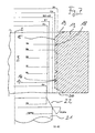
- Another object of the invention is a screw, comprising a nut and a bolt, wherein the diameter d2 of the bolt is greater than the threaded inner diameter D1 and smaller than the outer circle diameter Da of the mother and in particular as large as the thread flute diameter D2.
- the outer circle diameter Da of the nut can be larger than the diameter d2 of the bolt.
- the resulting screw has a high self-locking effect, which is similar to thread-forming screws caused by the elastic resilience of the material during the forming and so one independent release of the connection, for example, counteracts by vibrations.
- Yet another object of the invention is a blank for the production of a thread-generating nut, wherein the nut to be produced is provided with a thread having a threaded inner diameter D1 and with a thread outer diameter Dn, in which the blank core hole with an inner circle diameter Di smaller than that Having produced thread inside diameter D1 and the core hole from the inner circle diameter Di forth the core hole widening free spaces, wherein the free spaces at a distance to be produced thread outer diameter Dn on an outer circle diameter Da ends.
- a nut according to the invention can be produced by cutting a thread.
- the free spaces may be spaced from each other, although it is also possible that the free spaces present in the blank abut each other.
- Fig. 1 shows a blank 1 for a mother with a thread still to be produced with threads according to the prior art, such as formed as a metric thread according to DIN 336, wherein the imaginary threads between a thread outer diameter Dn with the radius Rn, referred to the ISO as the standard diameter and a threaded internal diameter D1 of radius R1, also referred to as the core diameter of the nut thread, shown as solid circles about a common center 2.
- the diameters Dn, D1 are associated with the radii Rn and R1, not shown, and hereinafter in the description between the radii and the diameters is not further distinguished and it will be used depending on the name that is considered better for the explanation of the invention becomes. This also applies to further diameters and radii of the following figures.
- a pitch diameter D2 with a radius R2 for the thread to be produced by the nut is important for the design of the bolt or pin on which the nut is to be applied, and will be explained in connection with FIG. 8.
- Fig. 2 shows the blank 1 for a mother Fig. 1 , wherein a core hole 3 has been introduced with an inner diameter Di with the radius Ri, such as by drilling, punching or forming.
- the inner diameter Di with the radius Ri of the core hole 3 is smaller than the thread internal diameter D1 having the radius R1 to be produced.
- an outside diameter Da with the radius Ra is indicated as a dash-dotted circle around the center 2, which has a special significance for the design of the nut according to the invention.
- pitch diameter D2 Fig. 1 and Fig. 8 with the radius R2, but which lies between the threaded inner diameter D1 with the radius R1 and the outer diameter Da with the radius Ra.
- Fig. 3 is the blank out Fig. 2 with a first modification of the core hole geometry, which has a rounded franking with a radius Rv and with a center 4 at a distance from the center 2 of the core hole 3.
- This change has arisen, for example, in that the core hole 2 has a milling cutter with a milling cutter circumference Rv and with a turning center 4 Fig. 2 was extended.
- the clearance Rv is smaller than the inner diameter Di of the radius RI, preferably, Rv is about half of Ri, and the center of rotation 4 is spaced from the center 2 so that the clearance reaches and still reaches the outer diameter Da of the radius Ra has a distance to be produced thread outer diameter Dn with the radius Rn.
- the thread internal diameter D1 with the radius R1 to be produced has fallen below.
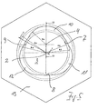
- Fig. 4 is the blank out Fig. 3 presented with a further change of the core hole geometry, which was created by the fact that further clearances were made.
- the center of rotation 5 and 6 is also spaced apart from the center 2, that the clearance again reaches up to the outer diameter Da with the radius Ra and still has a distance to the produced thread outer diameter Dn with the radius Rn.
- the production is carried out, for example, with the cutter with a cutter circumference Rv in addition to the center of rotation 4 to two more centers of rotation 5 and 6.
- FIG. 4 Next is in Fig. 4 to recognize that there are areas 10, 11, 12 of the core hole, which are opposite to the produced thread inner diameter D1 with the radius R1 to the outer diameter Da with the radius Ra, the area 10 already in Fig. 3 had arisen.
- Fig. 4A In the detailed view X of the area 10 off Fig. 4 is in the Fig. 4A its position with respect to the different diameters Di, D1, Da and Dn with the respective radius Ri, R1, Ra and Rn to recognize exactly, wherein the diameters are again indicated from the interior of the core hole 3 to the outside.
- the center 4 and the franking are indicated by a radius Rv with which the area 10 is made.
- the free spaces 10 - 12 adjoin one another, they may also be designed such that intermediate spaces with an unchanged inner circle diameter Di are present.
- the scope of design is very wide here.
- Fig. 5 is the blank out Fig. 4 shown with yet another change of the core hole geometry, which is created by the fact that when cutting the thread with a tap all areas 7, 8, 9 from Fig. 4 were shortened from the inner diameter Di with the radius Ri to the now produced threaded inner diameter D1 with the radius R1, so that in these areas 7, 8, 9 is now a tip of a complete, sharp-edged thread, see later Fig. 7 to the section II.
- Fig. 7 is the blank out Fig. 4 shown with yet another change of the core hole geometry, which is created by the fact that when cutting the thread with a tap all areas 7, 8, 9 from Fig. 4 were shortened from the inner diameter Di with the radius Ri to the now produced threaded inner diameter D1 with the radius R1, so that in these areas 7, 8, 9 is now a tip of a complete, sharp-edged thread, see later Fig. 7 to the section II.
- the thread of the outer thread diameter Dn with the radius Rn and thus a nut 13 according to the invention.
- Fig. 5 the free space of the area 10 and the projection of the area 7 of the nut 13 are made Fig. 5 shown in detail.
- the center 2 of the core hole 3 which is displaced center 4 for producing the free space to the outer diameter Da with the radius Ra in the region 10 with a diameter Rv and lying on the threaded inner diameter D1 with the radius R1 projection in the area 7th
- the thread extends up to the outer thread diameter Dn with the radius RD.
- the inner diameter Di with the radius Ri of the blank from the Fig. 2 to 4 has in the mother thus produced no representational correspondence more and is given only for the sake of completeness.
- the angle at the transition of the region 9 to the franking 10 is about 170 ° measured in the material of the nut.
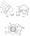
- Fig. 6 is a cut II off Fig. 5 represented by the area 9.
- the nut 13 has here in the core hole 3 a thread 14 with a plurality of threads, which consist of a core hole facing thread crest 15, of thread flanks 16, 17 and a thread base 18.
- the thread crests 15 are fully formed and sharp-edged and lie on the threaded inner diameter D1 with the radius R1, according to the ISO also referred to as the core diameter of the nut thread.
- the roots 18 are located on a thread outer diameter Dn with the radius Rn, referred to the ISO as the standard diameter.
- the nut 13 is also provided on the top and bottom with inlet slopes 19, 20 to facilitate attachment to a bolt or pin.
- Fig. 7 is a section II-II off Fig. 5 represented by the area 10.
- the thread 14 has a plurality of threads, the core hole facing the threaded tips 15 'are formed only incomplete and substantially flat, although still thread flanks 16, 17 continue to the thread bottom 18 out.
- the roots 18 are located on a thread outer diameter Dn with the radius Rn, referred to the ISO as the standard diameter.
- the flank diameter D2 with radius R2 corresponds to the outer diameter d2 of a bolt 21.
- the bolt 21 has an insertion bevel 22 with an angle alpha of about 60 ° and at the tip a smallest diameter ds with a radius rs smaller than the threaded inner diameter D1.
- the nut 13 has on both sides, but at least on the side facing the component to be clamped, ie in the direction of action of the mother via a correspondingly strong countersink 19, 20 or a threaded inlet, the attachment of the mother and so the furrows of a thread should facilitate. Therefore, at nuts of this type, which are not installed position-oriented and thus inevitably on both sides have such a countersink 19, 20, a corresponding addition to the nut height can be selected to ensure sufficient load capacity of the compound. A larger nut height may also be desirable because the threads do not support the full circumference and an increased number of threads should be provided to balance the non-bearing portion of the thread.
- the nut described above is preferably made of hardenable steel, with a distinction must be made depending on the purpose of the strength class of the mother.
- the strength class FK 10 according to ISO 898-2 with conventionally tempered carbon steel has a limited suitability for thread forming for soft materials with a strength Rm ⁇ 700 N / mm 2 .
- the strength class FK 14 with a hardness of 430-470 HV10 made of, for example, bainitic-coated carbon steel with additives has a special suitability for thread forming even for higher-strength materials with a strength Rm ⁇ 1100 N / mm 2 .
- the mother has as a blank prior to the introduction of the thread on a special Kernlochgeometrie, which leaves after the introduction of the thread in the nut body defined open spaces on the thread profile produced.
- the core hole cross-section corresponds to that of a cloverleaf, but other shapes are possible, wherein the circumscribing outer circle diameter Da is based on the nominal outer thread diameter Dn and the inner circle diameter Di is based on the nominal threaded inner diameter D1 with the radius R1, but this falls below.
- the outer circle diameter Da with the radius Ra, depending on the nominal diameter of the nut is slightly larger than the outer diameter d2 selected with the radius R2 of the bolt, so on the one hand to create appropriate open spaces for the flow of material, on the other hand, but at the same time still effective on the tips of to be forming stud thread.
- the outer diameter R2 of the bolt 21 is at the same time smaller than the nominal outer thread diameter Dn with the radius Rn of the nut 13 and is of the order of the pitch diameter D2 of the thread.
- the degree of expansion of the core hole can be varied, so that with a large expansion correspondingly larger open spaces arise, which accommodates a conschaben added threads because of the possibility of chip receiving in the open spaces.
- the proportion of the load-bearing thread is increased, which increases the suitability for thread forming.
- the height of the nut must be adapted to the required conditions in relation to the load-bearing threaded portion.
- the nut according to the invention can be used both on unthreaded bolts or cones and on existing, coated Are threaded and generates the required thread conditions on the bolt by grooves or cutting or clearances.
Applications Claiming Priority (2)
| Application Number | Priority Date | Filing Date | Title |
|---|---|---|---|
| DE102010043589A DE102010043589A1 (de) | 2010-11-08 | 2010-11-08 | Gewindeerzeugende Mutter, Rohteil zur Herstellung der Mutter und Schraubverbindung aus Mutter und Bolzen |
| PCT/EP2011/069601 WO2012062728A1 (de) | 2010-11-08 | 2011-11-08 | Gewindeerzeugende mutter, rohteil zur herstellung der mutter und schraubverbindung aus mutter und bolzen |
Publications (2)
| Publication Number | Publication Date |
|---|---|
| EP2638298A1 EP2638298A1 (de) | 2013-09-18 |
| EP2638298B1 true EP2638298B1 (de) | 2015-05-06 |
Family
ID=45094584
Family Applications (1)
| Application Number | Title | Priority Date | Filing Date |
|---|---|---|---|
| EP20110791227 Active EP2638298B1 (de) | 2010-11-08 | 2011-11-08 | Gewindeerzeugende mutter, rohteil zur herstellung der mutter und schraubverbindung aus mutter und bolzen |
Country Status (12)
| Country | Link |
|---|---|
| US (1) | US8770903B2 (pt) |
| EP (1) | EP2638298B1 (pt) |
| JP (1) | JP5973451B2 (pt) |
| KR (1) | KR20130101110A (pt) |
| CN (1) | CN103328834B (pt) |
| AU (1) | AU2011328261B2 (pt) |
| BR (1) | BR112013011254B1 (pt) |
| DE (1) | DE102010043589A1 (pt) |
| ES (1) | ES2543616T3 (pt) |
| MX (1) | MX2013005180A (pt) |
| RU (1) | RU2572775C2 (pt) |
| WO (1) | WO2012062728A1 (pt) |
Families Citing this family (9)
| Publication number | Priority date | Publication date | Assignee | Title |
|---|---|---|---|---|
| FR2947597A1 (fr) * | 2009-07-06 | 2011-01-07 | Lisi Aerospace | Procede de freinage d'un ecrou en materiau a faible capacite de deformation plastique |
| CN105026705B (zh) * | 2013-02-25 | 2018-01-02 | 夏伊洛工业公司 | 具有压入配合紧固件孔的模块化组件 |
| US9228385B2 (en) * | 2013-08-28 | 2016-01-05 | Cornell Ironworks Enterprises | Apparatus and method for extending door brake lifespan |
| FR3010156B1 (fr) | 2013-08-30 | 2016-02-26 | Faurecia Interieur Ind | Element de fixation filete |
| GB201618301D0 (en) * | 2016-10-28 | 2016-12-14 | Excalibur Screwbolts Ltd | Improvements in or relating to screwbolts |
| CN107030324B (zh) * | 2017-05-12 | 2019-03-12 | 株洲钻石切削刀具股份有限公司 | 一种切削刀具 |
| IL258480B (en) * | 2018-04-01 | 2018-10-31 | Chen Ami | Drill screw and nut |
| CN112709745B (zh) * | 2020-12-22 | 2022-06-10 | 淄博齐美特化工装备有限公司 | 一种螺钉紧固件 |
| CN113339379B (zh) * | 2021-06-03 | 2023-04-07 | 上海亿泊材料应用技术有限公司 | 一种螺纹连接结构及其设计方法 |
Family Cites Families (19)
| Publication number | Priority date | Publication date | Assignee | Title |
|---|---|---|---|---|
| US561913A (en) * | 1896-06-09 | stoughton | ||
| NL129061C (pt) * | 1963-07-18 | |||
| US3314326A (en) * | 1964-10-20 | 1967-04-18 | Republic Ind Corp | Self-threading nut with interrupted threads |
| US3331272A (en) * | 1965-05-24 | 1967-07-18 | Illinois Tool Works | Thread forming nut and tapered stud |
| US4352219A (en) * | 1979-03-05 | 1982-10-05 | Mcmurray John C | Prevailing torque lock nut and method of forming same |
| US4347636A (en) * | 1979-11-07 | 1982-09-07 | Lamson & Sessions Co. | Nut and method of forming the same |
| DE3332570A1 (de) * | 1983-09-09 | 1985-03-28 | Friedr. Boesner GmbH, 5450 Neuwied | Verfahren zur herstellung von selbstformenden und selbstsichernden schrauben mit zusaetzlicher abdicht- und/oder stell-eigenschaft |
| JPS62172818U (pt) * | 1986-04-22 | 1987-11-02 | ||
| US4842437A (en) * | 1987-11-16 | 1989-06-27 | Ryder International Corporation | Thread forming nut with locking portion |
| US4907930A (en) | 1988-08-10 | 1990-03-13 | Buell Industries, Inc. | Anti cross thread nut |
| JPH0765609B2 (ja) * | 1988-10-19 | 1995-07-19 | 株式会社青山製作所 | 自動調芯用ナット |
| DE9201043U1 (pt) * | 1992-01-29 | 1992-03-12 | Emhart Inc., Newark, Del., Us | |
| DE29614832U1 (de) | 1996-08-26 | 1997-01-02 | Trw Repa Gmbh | Befestigungsmittel bei einem Fahrzeuginsassen-Rückhaltesystem |
| JP2933906B1 (ja) * | 1998-02-05 | 1999-08-16 | 株式会社青山製作所 | アースナット |
| CN2373609Y (zh) * | 1998-05-26 | 2000-04-12 | 许水清 | 一种新型的自攻螺丝 |
| EP1576296A4 (en) * | 2002-12-05 | 2006-09-27 | Whitesell Int Corp | AUTOMATIC THREAD FEMALE FASTENING ELEMENT AND METHOD OF MANUFACTURING THE SAME |
| EP1791548A1 (en) | 2004-07-27 | 2007-06-06 | Modus Biological Membranes Ltd. | Compositions and methods for smoking cessation |
| DE102005020530A1 (de) * | 2005-05-03 | 2006-11-16 | Schaeffler Kg | Verbindungsanordnung zwischen einer Laufrolle und einer Spannvorrichtung |
| RU61370U1 (ru) * | 2006-10-09 | 2007-02-27 | Открытое акционерное общество "АВТОВАЗ" | Гайка самонарезная самоцентрирующаяся |
-
2010
- 2010-11-08 DE DE102010043589A patent/DE102010043589A1/de not_active Withdrawn
-
2011
- 2011-11-08 EP EP20110791227 patent/EP2638298B1/de active Active
- 2011-11-08 KR KR1020137014743A patent/KR20130101110A/ko not_active Application Discontinuation
- 2011-11-08 CN CN201180053857.4A patent/CN103328834B/zh active Active
- 2011-11-08 JP JP2013537164A patent/JP5973451B2/ja active Active
- 2011-11-08 BR BR112013011254-9A patent/BR112013011254B1/pt active IP Right Grant
- 2011-11-08 US US13/883,703 patent/US8770903B2/en active Active
- 2011-11-08 RU RU2013125000/12A patent/RU2572775C2/ru active
- 2011-11-08 WO PCT/EP2011/069601 patent/WO2012062728A1/de active Application Filing
- 2011-11-08 MX MX2013005180A patent/MX2013005180A/es active IP Right Grant
- 2011-11-08 AU AU2011328261A patent/AU2011328261B2/en not_active Ceased
- 2011-11-08 ES ES11791227.9T patent/ES2543616T3/es active Active
Also Published As
| Publication number | Publication date |
|---|---|
| CN103328834A (zh) | 2013-09-25 |
| MX2013005180A (es) | 2013-07-03 |
| WO2012062728A1 (de) | 2012-05-18 |
| DE102010043589A1 (de) | 2012-05-10 |
| BR112013011254B1 (pt) | 2020-06-16 |
| EP2638298A1 (de) | 2013-09-18 |
| BR112013011254A2 (pt) | 2016-11-01 |
| AU2011328261B2 (en) | 2016-02-11 |
| RU2572775C2 (ru) | 2016-01-20 |
| ES2543616T3 (es) | 2015-08-20 |
| US20130223954A1 (en) | 2013-08-29 |
| RU2013125000A (ru) | 2014-12-20 |
| CN103328834B (zh) | 2016-06-01 |
| JP2013541684A (ja) | 2013-11-14 |
| AU2011328261A1 (en) | 2013-05-30 |
| JP5973451B2 (ja) | 2016-08-23 |
| US8770903B2 (en) | 2014-07-08 |
| KR20130101110A (ko) | 2013-09-12 |
Similar Documents
| Publication | Publication Date | Title |
|---|---|---|
| EP2638298B1 (de) | Gewindeerzeugende mutter, rohteil zur herstellung der mutter und schraubverbindung aus mutter und bolzen | |
| EP1715198B1 (de) | Verbindungsanordnung mit einem Kunststoff-Trägerteil und einem Kunststoff-Gewindeelement | |
| EP2809958A2 (de) | Mutter | |
| EP0627568B1 (de) | Presspassverbindungselement, insbesondere Radbolzen | |
| DE102008042141A1 (de) | Selbstzentrierende Schraube | |
| EP1754894B1 (de) | Presspassverbindungselement und Verfahren zu dessen Herstellung | |
| EP2982874B1 (de) | Schraubdom zum befestigen eines bauteils | |
| EP3377777B1 (de) | Gewindeformende oder gewindefurchende schraube, insbesondere zur verwendung in leichtmetall | |
| EP3719330B1 (de) | Schraube mit diskontinuität an zwischengewindeabschnitt | |
| WO2014044677A1 (de) | Gewindehülse, profilverbindung sowie verfahren zum herstellen einer profilverbindung | |
| EP1929163B2 (de) | Gewindebuchse, verfahren zum erneuern eines gewindes und werkzeug hierfür | |
| EP3477127B1 (de) | Schraube zum einschrauben in ein bohrloch | |
| EP2497962B1 (de) | Gewindehülse | |
| WO2017102376A1 (de) | Gewindeelement | |
| DE102017103073B4 (de) | Werkzeug zum Gewindewalzen einer gewindeformenden Schraube, Verfahren zum Herstellen einer lochformenden und/oder gewindeformenden Schraube, sowie eine gewindeformende und/oder lochformende Schraube | |
| DE2157373A1 (de) | Selbsthaltendes Befestigungselement und Werkzeug zu seiner Herstellung | |
| EP2961544A1 (de) | Verfahren zum herstellen einer betonschraube | |
| DE102014014086A1 (de) | Schraube und Schraubenanordnung | |
| DE102013203148A1 (de) | Herstellungsverfahren für Schrauben und Betonschraube | |
| EP3519708A1 (de) | Sicherungsinnengewindeelement, gewindeverbindung sowie herstellverfahren und werkzeug | |
| WO2017032423A1 (de) | Bohrschraube | |
| DE102016105622B4 (de) | Verfahren zur Herstellung eines Schraubankers mit einem metrischen Anschlussgewinde | |
| DE10304182B4 (de) | Gewindeformer oder -bohrer | |
| DE102014013273A1 (de) | Befestigungsanordnung einer gewindefurchenden Schraube an einem Bauteil aus einem Aluminiumwerkstoff | |
| DE102013106403A1 (de) | Abgerundet quadratische, selbstschneidende Gewindeform für Befestigungselemente und Herstellungsverfahren dazu |
Legal Events
| Date | Code | Title | Description |
|---|---|---|---|
| PUAI | Public reference made under article 153(3) epc to a published international application that has entered the european phase |
Free format text: ORIGINAL CODE: 0009012 |
|
| 17P | Request for examination filed |
Effective date: 20130527 |
|
| AK | Designated contracting states |
Kind code of ref document: A1 Designated state(s): AL AT BE BG CH CY CZ DE DK EE ES FI FR GB GR HR HU IE IS IT LI LT LU LV MC MK MT NL NO PL PT RO RS SE SI SK SM TR |
|
| DAX | Request for extension of the european patent (deleted) | ||
| GRAP | Despatch of communication of intention to grant a patent |
Free format text: ORIGINAL CODE: EPIDOSNIGR1 |
|
| INTG | Intention to grant announced |
Effective date: 20141017 |
|
| GRAS | Grant fee paid |
Free format text: ORIGINAL CODE: EPIDOSNIGR3 |
|
| RBV | Designated contracting states (corrected) |
Designated state(s): DE ES FR GB IT NL TR |
|
| GRAA | (expected) grant |
Free format text: ORIGINAL CODE: 0009210 |
|
| AK | Designated contracting states |
Kind code of ref document: B1 Designated state(s): DE ES FR GB IT NL TR |
|
| REG | Reference to a national code |
Ref country code: GB Ref legal event code: FG4D Free format text: NOT ENGLISH |
|
| REG | Reference to a national code |
Ref country code: DE Ref legal event code: R096 Ref document number: 502011006817 Country of ref document: DE Effective date: 20150618 |
|
| REG | Reference to a national code |
Ref country code: NL Ref legal event code: T3 |
|
| REG | Reference to a national code |
Ref country code: ES Ref legal event code: FG2A Ref document number: 2543616 Country of ref document: ES Kind code of ref document: T3 Effective date: 20150820 |
|
| REG | Reference to a national code |
Ref country code: FR Ref legal event code: PLFP Year of fee payment: 5 |
|
| REG | Reference to a national code |
Ref country code: DE Ref legal event code: R097 Ref document number: 502011006817 Country of ref document: DE |
|
| PLBE | No opposition filed within time limit |
Free format text: ORIGINAL CODE: 0009261 |
|
| STAA | Information on the status of an ep patent application or granted ep patent |
Free format text: STATUS: NO OPPOSITION FILED WITHIN TIME LIMIT |
|
| 26N | No opposition filed |
Effective date: 20160209 |
|
| REG | Reference to a national code |
Ref country code: FR Ref legal event code: PLFP Year of fee payment: 6 |
|
| REG | Reference to a national code |
Ref country code: FR Ref legal event code: PLFP Year of fee payment: 7 |
|
| REG | Reference to a national code |
Ref country code: DE Ref legal event code: R082 Ref document number: 502011006817 Country of ref document: DE Representative=s name: JONES DAY RECHTSANWAELTE PATENTANWAELTE, DE Ref country code: DE Ref legal event code: R082 Ref document number: 502011006817 Country of ref document: DE Representative=s name: SOMMER, PETER, DIPL.-WIRTSCH.-ING., DE |
|
| REG | Reference to a national code |
Ref country code: DE Ref legal event code: R082 Ref document number: 502011006817 Country of ref document: DE Representative=s name: SOMMER, PETER, DIPL.-WIRTSCH.-ING., DE |
|
| PGFP | Annual fee paid to national office [announced via postgrant information from national office to epo] |
Ref country code: NL Payment date: 20231127 Year of fee payment: 13 |
|
| PGFP | Annual fee paid to national office [announced via postgrant information from national office to epo] |
Ref country code: GB Payment date: 20231123 Year of fee payment: 13 |
|
| PGFP | Annual fee paid to national office [announced via postgrant information from national office to epo] |
Ref country code: ES Payment date: 20231201 Year of fee payment: 13 |
|
| PGFP | Annual fee paid to national office [announced via postgrant information from national office to epo] |
Ref country code: TR Payment date: 20231026 Year of fee payment: 13 Ref country code: IT Payment date: 20231129 Year of fee payment: 13 Ref country code: FR Payment date: 20231127 Year of fee payment: 13 Ref country code: DE Payment date: 20231121 Year of fee payment: 13 |