EP2638271B1 - Vorrichtung zur selbstgenerierung einer überspannung und zur simultanen steuerung eines aus einer oder mehreren induktivitäten bestehenden aktuators, und steuerverfahren dafür - Google Patents
Vorrichtung zur selbstgenerierung einer überspannung und zur simultanen steuerung eines aus einer oder mehreren induktivitäten bestehenden aktuators, und steuerverfahren dafür Download PDFInfo
- Publication number
- EP2638271B1 EP2638271B1 EP11794813.3A EP11794813A EP2638271B1 EP 2638271 B1 EP2638271 B1 EP 2638271B1 EP 11794813 A EP11794813 A EP 11794813A EP 2638271 B1 EP2638271 B1 EP 2638271B1
- Authority
- EP
- European Patent Office
- Prior art keywords
- inductance
- actuator
- coil
- voltage
- switching elements
- Prior art date
- Legal status (The legal status is an assumption and is not a legal conclusion. Google has not performed a legal analysis and makes no representation as to the accuracy of the status listed.)
- Not-in-force
Links
Images



Classifications
-
- H—ELECTRICITY
- H02—GENERATION; CONVERSION OR DISTRIBUTION OF ELECTRIC POWER
- H02M—APPARATUS FOR CONVERSION BETWEEN AC AND AC, BETWEEN AC AND DC, OR BETWEEN DC AND DC, AND FOR USE WITH MAINS OR SIMILAR POWER SUPPLY SYSTEMS; CONVERSION OF DC OR AC INPUT POWER INTO SURGE OUTPUT POWER; CONTROL OR REGULATION THEREOF
- H02M3/00—Conversion of DC power input into DC power output
- H02M3/02—Conversion of DC power input into DC power output without intermediate conversion into AC
- H02M3/04—Conversion of DC power input into DC power output without intermediate conversion into AC by static converters
- H02M3/10—Conversion of DC power input into DC power output without intermediate conversion into AC by static converters using discharge tubes with control electrode or semiconductor devices with control electrode
- H02M3/145—Conversion of DC power input into DC power output without intermediate conversion into AC by static converters using discharge tubes with control electrode or semiconductor devices with control electrode using devices of a triode or transistor type requiring continuous application of a control signal
- H02M3/155—Conversion of DC power input into DC power output without intermediate conversion into AC by static converters using discharge tubes with control electrode or semiconductor devices with control electrode using devices of a triode or transistor type requiring continuous application of a control signal using semiconductor devices only
- H02M3/156—Conversion of DC power input into DC power output without intermediate conversion into AC by static converters using discharge tubes with control electrode or semiconductor devices with control electrode using devices of a triode or transistor type requiring continuous application of a control signal using semiconductor devices only with automatic control of output voltage or current, e.g. switching regulators
- H02M3/158—Conversion of DC power input into DC power output without intermediate conversion into AC by static converters using discharge tubes with control electrode or semiconductor devices with control electrode using devices of a triode or transistor type requiring continuous application of a control signal using semiconductor devices only with automatic control of output voltage or current, e.g. switching regulators including plural semiconductor devices as final control devices for a single load
-
- H—ELECTRICITY
- H01—ELECTRIC ELEMENTS
- H01F—MAGNETS; INDUCTANCES; TRANSFORMERS; SELECTION OF MATERIALS FOR THEIR MAGNETIC PROPERTIES
- H01F7/00—Magnets
- H01F7/06—Electromagnets; Actuators including electromagnets
- H01F7/08—Electromagnets; Actuators including electromagnets with armatures
- H01F7/18—Circuit arrangements for obtaining desired operating characteristics, e.g. for slow operation, for sequential energisation of windings, for high-speed energisation of windings
-
- H—ELECTRICITY
- H01—ELECTRIC ELEMENTS
- H01H—ELECTRIC SWITCHES; RELAYS; SELECTORS; EMERGENCY PROTECTIVE DEVICES
- H01H47/00—Circuit arrangements not adapted to a particular application of the relay and designed to obtain desired operating characteristics or to provide energising current
- H01H47/22—Circuit arrangements not adapted to a particular application of the relay and designed to obtain desired operating characteristics or to provide energising current for supplying energising current for relay coil
- H01H47/32—Energising current supplied by semiconductor device
- H01H47/325—Energising current supplied by semiconductor device by switching regulator
-
- H—ELECTRICITY
- H02—GENERATION; CONVERSION OR DISTRIBUTION OF ELECTRIC POWER
- H02M—APPARATUS FOR CONVERSION BETWEEN AC AND AC, BETWEEN AC AND DC, OR BETWEEN DC AND DC, AND FOR USE WITH MAINS OR SIMILAR POWER SUPPLY SYSTEMS; CONVERSION OF DC OR AC INPUT POWER INTO SURGE OUTPUT POWER; CONTROL OR REGULATION THEREOF
- H02M3/00—Conversion of DC power input into DC power output
- H02M3/02—Conversion of DC power input into DC power output without intermediate conversion into AC
- H02M3/04—Conversion of DC power input into DC power output without intermediate conversion into AC by static converters
- H02M3/10—Conversion of DC power input into DC power output without intermediate conversion into AC by static converters using discharge tubes with control electrode or semiconductor devices with control electrode
- H02M3/145—Conversion of DC power input into DC power output without intermediate conversion into AC by static converters using discharge tubes with control electrode or semiconductor devices with control electrode using devices of a triode or transistor type requiring continuous application of a control signal
- H02M3/155—Conversion of DC power input into DC power output without intermediate conversion into AC by static converters using discharge tubes with control electrode or semiconductor devices with control electrode using devices of a triode or transistor type requiring continuous application of a control signal using semiconductor devices only
- H02M3/1552—Boost converters exploiting the leakage inductance of a transformer or of an alternator as boost inductor
-
- H—ELECTRICITY
- H02—GENERATION; CONVERSION OR DISTRIBUTION OF ELECTRIC POWER
- H02M—APPARATUS FOR CONVERSION BETWEEN AC AND AC, BETWEEN AC AND DC, OR BETWEEN DC AND DC, AND FOR USE WITH MAINS OR SIMILAR POWER SUPPLY SYSTEMS; CONVERSION OF DC OR AC INPUT POWER INTO SURGE OUTPUT POWER; CONTROL OR REGULATION THEREOF
- H02M3/00—Conversion of DC power input into DC power output
- H02M3/02—Conversion of DC power input into DC power output without intermediate conversion into AC
- H02M3/04—Conversion of DC power input into DC power output without intermediate conversion into AC by static converters
- H02M3/10—Conversion of DC power input into DC power output without intermediate conversion into AC by static converters using discharge tubes with control electrode or semiconductor devices with control electrode
- H02M3/145—Conversion of DC power input into DC power output without intermediate conversion into AC by static converters using discharge tubes with control electrode or semiconductor devices with control electrode using devices of a triode or transistor type requiring continuous application of a control signal
- H02M3/155—Conversion of DC power input into DC power output without intermediate conversion into AC by static converters using discharge tubes with control electrode or semiconductor devices with control electrode using devices of a triode or transistor type requiring continuous application of a control signal using semiconductor devices only
- H02M3/1555—Conversion of DC power input into DC power output without intermediate conversion into AC by static converters using discharge tubes with control electrode or semiconductor devices with control electrode using devices of a triode or transistor type requiring continuous application of a control signal using semiconductor devices only for the generation of a regulated current to a load whose impedance is substantially inductive
Definitions
- the invention relates to a device for simultaneously raising the voltage and controlling an actuator comprising at least one inductor.
- the invention also relates to a method of raising the supply voltage across such a device and a method of controlling such an actuator.
- electromagnetic actuators In many automotive applications, such as the control of electromagnetic valves, the control of injectors or the control of electric motors for electric or hybrid vehicles, electromagnetic actuators are used.
- An actuator is a device capable of acting in response to an electrical command.
- an actuator is provided with at least one inductor (or self-inductance) which, when traversed by a current, causes the displacement of a moving part (the electromagnetic valve for example).
- the actuator In the case of an electromagnetic valve, the actuator generally consists of two electromagnets: one is dedicated to opening the valve and the other to closing the valve.
- the valve is mechanically connected to a pallet which is located in the air gap of the electromagnets.
- the pallet is attracted by one or the other of the electromagnets by electromagnetic forces when the electromagnets are magnetized and it is recalled in the center of the air gap by springs.
- Actuator control usually takes place from a DC voltage source. Therefore, it is often necessary to adopt an H-bridge architecture to control this actuator in the four quadrants.
- FIG. 1 represents a device of the prior art, in which a voltage booster 2 is disposed between the power source 1 and the H 3 bridge in which the inductor 4 of the actuator is located.
- Such an overvoltage generator is generally connected to the H bridge in which the inductor of the actuator is located.
- the inductance of the actuator is used to perform the function of raising the voltage.
- a switch toggles the device from the "voltage booster” mode to the "actuator control” mode and vice versa. This device makes it possible to reduce the number of components used.
- the document US6175484 describes an assembly, intended for the injectors, in which the inductance of the actuator is reused to perform the function of voltage rise.
- the actuator can be powered by low voltage from the battery or by high voltage from the capacitor.
- the invention aims to overcome the disadvantages of the state of the art by proposing a device for controlling an actuator and simultaneously raising the voltage, which allows a saving of space by reusing components of the actuator to achieve the surge.
- Another object of the invention is to propose a device which simultaneously makes it possible to realize the raising of the voltage and the control of the actuator by means of common components, while keeping these two functions independent of each other .
- the device according to the invention may further comprise a load having a first terminal and a second terminal.
- the load can be connected in parallel with the first or second arm of the H-bridge.
- the first terminal of the load is therefore connected to the second terminal of Q2 or Q1.
- the second terminal of the load is connected to ground.
- the first inductor which is part of the actuator to be controlled, is separated into two coil portions which are coupled.
- This coupling is obtained in particular when the two coil portions surround the same magnetic core, so that when a current is sent into the first coil portion and the opposite current in the second coil portion, their mutual effects cancel each other out, said current and the opposite current having a ratio equal to the ratio of the number of turns of the first and the second coil portion.
- no electromotive force is created by the first inductor as a whole and the magnetic core that the two coil portions surround does not move.
- a power source is connected to this intermediate terminal.
- Connecting the power source to the intermediate terminal of the first inductor of the actuator makes it possible to create an overvoltage using the first inductor without affecting the control of the actuator.
- the supply currents coming from the power source flow in the two coil portions in opposite directions and according to values proportional to the number of coils. turns of the coil portion traversed, which cancels the overall electromotive force of the first inductor when generating the overvoltage.
- the device according to the invention therefore makes the functions "voltage rise” and "control of the actuator” independent.
- the currents I 1 and I 2 are controlled by means of switching elements Q1, Q2, Q3, Q4.
- the duty cycle of these switching elements is chosen to allow either only the rise of the voltage, or only the creation of an electromotive force in the first inductor, or to allow both.
- cyclic ratio is meant the percentages of opening and closing of each switching element.
- the switching elements Q3 and Q4 must have the same duty cycle. On the contrary, to create an electromotive force, the cyclic ratios of Q3 and Q4 must be different from each other.
- a first diode is inserted between the intermediate terminal of the first inductor and the power source.
- This first diode makes it possible to prevent the presence of the power source on the intermediate terminal from altering the voltage dynamics of the actuator. With this first diode, the intermediate terminal can take a potential different from that imposed by the power source.
- the power source is a 12 V battery, which makes it easy to use this device in the automotive field.
- This power source is connected between the ground and the intermediate terminal. More generally, the power source can deliver a DC voltage, this voltage being in particular between 6V and 18V.
- the current delivered by the power source may have a value of the order of 1A.
- the first inductor is preferably a coil.
- the two coil portions have the same number of turns, and are then called half-coils.
- Each switching element is preferably a transistor.
- the charge is constituted by a capacitor.
- the first inductor is preferably a coil.
- Each portion of the coil may have an inductance of the order of a few mH.
- the actuator is for example an electromagnetic valve actuator, in which case the device forms a device for controlling at least one electromagnetic valve actuator.
- the invention may then relate to an assembly comprising the electromagnetic valve actuator (s) control device and said actuator (s).
- the first inductor preferably allows the displacement of the actuated part in one direction, the second inductance allowing the displacement of the actuated part in the opposite direction.
- a second diode is inserted between the intermediate terminal of the second inductor and the power source.
- the second inductor is preferably a coil.
- the two coil portions of the second inductor are coupled, i.e., they surround the same magnetic core.
- the two coil portions of the second inductor have the same number of turns and are wound around the same second magnetic core.
- the invention is particularly suitable in the case where the actuator is an actuator for electromagnetic valve.
- the invention also relates to a method for raising the voltage across the load of a device as described above, the method comprising a step of controlling, with the aid of the switching elements, the sum of the currents flowing through each of the coil portions.
- the current supplied by the power source is used to supply the supply network of the control of the actuator.
- cyclic ratios equal to Q1, Q2 and Q3, Q4 are preferably chosen.
- the invention also relates to a control method of an actuator using the device as described above, this method comprising a step of controlling, using the switching elements, the difference of currents flowing through each portion. coil of the first inductor.
- the current I A useful for the generation of the electromotive force is equal to the current I 2 which flows through the second coil portion of the first inductor, minus the current I 1 which flows through the first portion of coil of the first inductor.
- Cyclic ratios can be selected which simultaneously raise the voltage and control the actuator. One can also choose cyclic ratios that perform only one function independently of the other.
- this arrangement makes it possible to perform the two functions of raising the voltage and controlling the actuator simultaneously and independently of one another.
- the invention also relates to a control method comprising a step of controlling, with the help of the switching elements, the difference of the currents flowing through each coil portion of the second inductor.
- control of the switching elements takes place with modulated signals in pulse width.
- the method according to the invention comprises a step of determining the cyclic ratios of the switching elements for raising the voltage across the load and / or controlling the actuator.
- At least one of the above methods is in particular implemented using a power source connected between the ground and at least one intermediate terminal of an inductor. delivering a DC voltage, for example between 6V and 18V.
- the Figures 2, 3 and 8 represent a device for the self-generation of an overvoltage and the simultaneous control of an actuator 9.
- This actuator 9 comprises a first inductor 9a and a movable part 9b also called actuated part.
- the first switching element Q1 has a first terminal 12 which is connected to the first terminal 10 of the first inductor 9a.
- the second switching element Q2 has a first terminal 13 which is connected to the second terminal 11 of the first inductor 9a.
- the third switching element Q3 has a first terminal 14 which is connected to the first terminal 10 of the first inductor 9a.
- the fourth switching element Q4 has a first terminal 15 which is connected to the second terminal 11 of the first inductor 9a.
- the second switching element Q2 has a second terminal 17 which is connected to the second terminal 16 of the first switching element Q1.
- the third and fourth switching elements Q3 and Q4 each have a second terminal 18 and 19 which are connected to ground.
- the device also comprises a load 20 which is a capacitor 21.
- This load 20 is connected in parallel with the second arm of the H bridge, that is to say that this load has a first terminal 22 which is connected with the second terminal 17 of Q2 and a second terminal 23 which is connected to ground.
- the first inductor 9a of the actuator is divided into two coil portions 24 and 25 which each have an inductance L1 and L2.
- the two half-coils 24 and 25 are coupled by their magnetic core which is the same for the two half-coils 24 and 25.
- I 1 the current flowing through the first half-coil 24 and I 2 the current flowing through the second half-coil 25.
- the device is particularly remarkable in that a power source 27 is connected to the midpoint 26.
- the power source has a voltage of 12 V.
- the invention is particularly remarkable in that the first inductance 9a that one wishes to control is also used to create an overvoltage, without the creation of this overvoltage has any influence on the actuator.
- leakage inductances Lf1 and Lf2 are very small, so that they do not disturb the actuator control. Moreover, the effects of the inductors L1 and L2 cancel each other out so that the creation of the overvoltage does not disturb the actuator despite the fact that the coil of the actuator is reused to create the overvoltage.
- I B I 1 + I 2 .
- the current I A required to control the actuator is obtained by closing Q1 / Q3 while Q2 / Q4 are open, and vice versa.
- the currents I 1 and I 2 must be equal. In this way, the current I A is zero but not the current I B.
- the device preferably comprises a diode 28 located between the power source 27 and the midpoint 26.
- FIGS. 6 and 7 represent an example of practical realization of the device. Indeed, for the device to work, it is necessary for the two half-coils 24 and 25 to be coupled, while each having a leakage inductance Lf1 and Lf2, these two leakage inductances Lf1 and Lf2 being distinct from each other. the other.
- the first inductance 9a can be constituted by two separate half-coils 24 and 25 which are placed in series on the magnetic circuit. A major leak is thus achieved because field lines of the half-coil 24 are looped without passing the half-coil 25 and vice versa.
- the half-coil 25 which is at the bottom of the assembly, has very few leaks compared to the high half-coil 24. This asymmetry is not a problem because the device according to the invention operates from at least one of the two leakage inductances Lf1 or Lf2 is sufficiently large to allow control of the overvoltage current I B.
- the figure 9 represents a device according to the invention. This device is particularly suitable for controlling an electromagnetic valve E-multicylinder valve.
- This device comprises a first and a second inductance 9a and 29a. These two inductances 9a and 29a are two coils that are part of the actuator.
- the first actuator coil is used to control the opening of the valve, while the second coil is used to control the closing of the valve.
- the first actuator coil 9a forms with the four switching elements Q1, Q2, Q3 and Q4 an H-bridge, the first coil 9a forming the horizontal bar of the H, the switching elements Q1, Q3 forming an arm of the H and switching elements Q2, Q4 forming the other arm of H.
- a load 20 is connected in parallel with the first arm of the bridge in H.
- the load 20 is a capacitor 21.
- the first inductor 9a is composed of two coil portions 24 and 25, each of which has an inductance L1 and L2.
- the first half-coil 24 of the first inductor 9a is traversed by a current I 1 .
- the second half-coil 25 of the first inductor 9a is traversed by a current I 2 .
- a power source 27 is connected to the midpoint 26 via a diode 28.
- the device according to the invention further comprises a second inductor 29a and two additional switching elements Q5 and Q6.
- the second inductor 29a has a first terminal 31 which is connected to the second terminal of the first inductor 9a.
- Q5 has a first terminal 30 which is connected to the second terminal 17 of Q2.
- Q5 also has a second terminal 32 which is connected to the second terminal 33 of the second inductor 33.
- Q6 has a first terminal 34 which is connected to the second terminal 33 of the second inductor 29a.
- Q6 has a second terminal 35 which is connected to ground.
- the first inductor 9a and the switching elements Q1, Q2, Q3, Q4 form a first H-bridge.
- the second inductor 29a and the switching elements Q2, Q4 and Q5, Q6 form a second H-bridge, the first H-bridge and the second H-bridge having one arm in common.
- the second inductor 29a is also divided into two coil portions 36 and 37 which each have an inductance L3 and L4.
- the first half-coil 36 of the second inductor 29a is traversed by a current I 3 .
- the second half-coil 37 of the second inductor 29a is traversed by a current I 4 .
- this terminal is in the present example a second midpoint 38.
- the power source 27 is connected at this second midpoint 38, preferably via a second diode 39.
- the device operates as follows: when it is desired to control the actuator, it is desired to open the valve and in this case, a current is created in the first inductor 9a by controlling the current I 2 - I 1 with the elements switch, or one wants to close the valve and in this case, a current is created in the second inductor by controlling the current I 4 - I 3 with the switching elements.
- a current is created in the first inductor 9a by controlling the current I 2 - I 1 with the elements switch, or one wants to close the valve and in this case, a current is created in the second inductor by controlling the current I 4 - I 3 with the switching elements.
- the switching elements Q2, Q4 and Q1, Q3 are alternately opened, the switching elements Q5, Q6 always being closed.
- the current I B is controlled which is equal to the sum of the currents I 1 , I 2 , I 3 , I 4 and therefore to raise the voltage across the terminals. of the charge, a leakage current is created in the two inductances 9a and 29a.
- the switching elements Q3, Q4, Q6 are opened at the same time and the elements Q1, Q2, Q5 on the other hand.
- the switching elements Q1, Q2, Q5 have the same duty cycle as the elements Q3, Q4, Q6.
- the element Q5 keeps the same duty cycle as the switching elements Q3, Q4 and Q6 and the cyclic ratios of the switching elements Q1 and Q2, i.e. cyclic ratios for Q3 and Q4 are chosen which are very different from one another.
- the element Q1 keeps the same duty cycle as the switching elements Q3, Q4 and Q6 and the cyclic ratios of the switching elements Q5 and Q6 are unbalanced. that is, we choose cyclic ratios for Q5 and Q6 which are very different from each other.
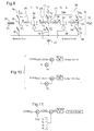
- the order of the "rise in voltage” takes place in the following way: as in the embodiment described above, the voltage that is desired to raise is the voltage V CD across the load 20.
- the voltage V DC is first compared to a reference voltage CONS DC .
- the error between the voltage V DC and the setpoint voltage CONS DC is compensated by a corrector of integral proportional type, which makes it possible to obtain an intensity control CONSi.
- This command CONSi is then compared to the sum of currents I 1 + I 2 + I 3 + I 4 .
- the error between the command CONSi and the sum of currents I 1 + I 2 + I 3 + I 4 is then compensated by a corrector of integral proportional type.
- This amplified error called a "boost error” is then compared to a sawtooth signal to generate a pulse width modulation command to control the opening and closing of the switching elements in order to have the voltage. V DC wanted.
- This control method makes it possible to compensate for a deviation of the voltage V DC .
- the voltage V DC is too large, the error between the voltage V DC and the setpoint voltage CONS DC is negative, which tends to reduce the current setpoint CONSi.
- the sum of currents I 1 + I 2 + I 3 + I 4 decreases.
- the own consumption of the actuator and / or all other loads connected to the network contributes to lowering the voltage.
- the figure 10 schematically represents the control method of the actuator according to the invention.
- to control the first inductance 9a it is necessary to control the difference of currents I 1 and I 2 which pass through the two half-coils of the first inductor.
- to control the second inductor 29a it is necessary to control the difference of currents I 3 and I 4 which pass through the two half-coils of the second inductor.
- These current differences are the image of the magnetomotive force created by each of the two inductances 9a and 29a. The regulation of these currents is known from the prior art.
- the figure 12 illustrates the use of three devices as described with reference to the figure 2 in an electric vehicle.
- This electric vehicle comprises a polyphase motor 40 which comprises three inductances which are three coils 41, 42 and 43. Each coil belongs to an H-bridge, respectively 44, 45 and 46. The H bridges are interconnected in parallel. A charge 47 which is a capacitor is connected in parallel with the H bridges.
- Each coil 41, 42, 43 is divided into two coil portions.
- An intermediate terminal 49, 50, 51 is between each coil portion of the same coil.
- Each intermediate terminal 49, 50, 51 is connected to a power source constituted by the battery 48 of the electric vehicle via a diode, respectively 52, 53, 54.
- the invention is not limited to the case where a single H-bridge is connected to the load and it is possible to connect different bridges in H at the same load. without departing from the scope of the invention.
- the device according to the invention makes it possible to raise the voltage of the battery of the electric vehicle, without having recourse to an additional voltage booster device, which makes it possible to limit the number of inductances used.
- the invention is not limited to the embodiments described above and different variants of these embodiments can be envisaged without departing from the scope of the invention.
- the embodiments given in the description of the figures relate to coil portions which are in these examples half-coils having an intermediate terminal which is therefore a midpoint, it being understood that these same embodiments may be implemented with coil portions having different numbers of turns and therefore a different inductance, as long as the currents injected into each coil portion to perform the overvoltage function are in a ratio substantially equal to the ratio of the inductances, so the overall electromotive force of the inductor is zero.
Landscapes
- Engineering & Computer Science (AREA)
- Power Engineering (AREA)
- Physics & Mathematics (AREA)
- Electromagnetism (AREA)
- Dc-Dc Converters (AREA)
Claims (14)
- Vorrichtung zur Selbstgenerierung einer Überspannung und gleichzeitigen Steuerung eines Aktors, der mindestens eine erste Drosselspule (9a) aufweist, wobei die erste Drosselspule (9a) von zwei gekoppelten Spulenabschnitten (24, 25) gebildet wird, zwischen denen sich eine Zwischenklemme (26) befindet,- wobei die erste Drosselspule (9a) mit vier Schaltelementen Q1, Q2, Q3 und Q4 verbunden ist, wobei die vier Schaltelemente Q1, Q2, Q3 und Q4 mit der ersten Drosselspule (9a) eine erste H-Brücke bilden, wobei die Schaltelemente Q1 und Q3 einen ersten Schenkel des H bilden, die Schaltelemente Q2 und Q4 einen zweiten Schenkel des H bilden, die erste Drosselspule den waagrechten Balken des H bildet;- wobei eine Last (20) parallel zu einem der Schenkel der H-Brücke verbunden ist;- wobei die Zwischenklemme (26) der ersten Drosselspule (9a) mit einer Versorgungsquelle (27) verbunden ist,dadurch gekennzeichnet, dass sie aufweist:- eine zweite Drosselspule (29a), wobei die zweite Drosselspule (29a) von zwei gekoppelten Spulenabschnitten (36, 37) gebildet wird, zwischen denen sich eine Zwischenklemme (38) befindet,- zwei zusätzliche Schaltelemente Q5 und Q6, wobei diese zwei zusätzlichen Schaltelemente Q5 und Q6 und die zweite Drosselspule (29a) mit der ersten H-Brücke so verbunden sind, dass die zwei zusätzlichen Schaltelemente Q5, Q6 und die zweite Drosselspule (29a) mit einem der Schenkel der ersten H-Brücke eine zweite H-Brücke bilden;
wobei die Versorgungsquelle (27) mit der Zwischenklemme (38) der zweiten Drosselspule (29a) verbunden ist. - Vorrichtung nach Anspruch 1, wobei eine erste Diode (28) zwischen die Versorgungsquelle (27) und die Zwischenklemme (26) eingefügt ist.
- Vorrichtung nach Anspruch 1 oder 2, wobei die Versorgungsquelle (27) eine Gleichspannungsquelle ist.
- Vorrichtung nach einem der vorhergehenden Ansprüche, wobei die zwei Spulenabschnitte (24, 25) um den gleichen Magnetkern (9b) gewickelt sind.
- Vorrichtung nach einem der vorhergehenden Ansprüche, wobei die zwei Spulenabschnitte (24, 25) Halbspulen sind, die die gleiche Anzahl von Windungen aufweisen, wobei die Zwischenklemme (26) dann ein Mittelpunkt ist.
- Vorrichtung nach einem der vorhergehenden Ansprüche, wobei die Last (20) aus einem Kondensator (21) besteht.
- Vorrichtung nach einem der vorhergehenden Ansprüche, wobei eine zweite Diode (39) zwischen die Zwischenklemme (38) der zweiten Drosselspule (29a) und die Versorgungsquelle (27) eingefügt ist.
- Vorrichtung nach einem der vorhergehenden Ansprüche, wobei die zwei Spulenabschnitte (36, 37) der zweiten Drosselspule (29a) um den gleichen zweiten Magnetkern gewickelt sind.
- Vorrichtung nach einem der vorhergehenden Ansprüche, wobei die zwei Spulenabschnitte (36, 37) Halbspulen sind, die die gleiche Anzahl von Windungen aufweisen, wobei die Zwischenklemme (38) dann ein Mittelpunkt ist.
- Vorrichtung nach einem der vorhergehenden Ansprüche, die konfiguriert ist, mindestens einen Aktor eines elektromagnetischen Ventils zu steuern.
- Einheit, die enthält:- die Vorrichtung nach Anspruch 10 und- mindestens einen Aktor eines elektromagnetischen Ventils.
- Verfahren zur Erhöhung der Spannung an den Klemmen der Last in der Vorrichtung nach einem der Ansprüche 1 bis 10, dadurch gekennzeichnet, dass es einen Schritt der Kontrolle, mit Hilfe der Schaltelemente, der Summe der Ströme (I1+I2, I1+I2+I3+I4) enthält, die jeden der Spulenabschnitte durchfließen.
- Verfahren zum Steuern des Aktors mit der Vorrichtung nach einem der Ansprüche 1 bis 10, das einen Schritt der Kontrolle, mit Hilfe der Schaltelemente, der Differenz der Ströme (I2-I1) aufweist, die jeden Spulenabschnitt der ersten Drosselspule (9a) durchfließen.
- Verfahren zum Steuern des Aktors mit der Vorrichtung nach einem der Ansprüche 1 bis 8, das einen Schritt der Kontrolle, mit Hilfe der Schaltelemente, der Differenz der Ströme (I4-I3) aufweist, die jeden Spulenabschnitt der zweiten Drosselspule (19a) durchfließen.
Applications Claiming Priority (2)
| Application Number | Priority Date | Filing Date | Title |
|---|---|---|---|
| FR1059300A FR2967316B1 (fr) | 2010-11-10 | 2010-11-10 | Dispositif pour l'auto-generation d'une surtension et la commande simultanee d'un actionneur comportant une ou plusieurs inductances, et procede de commande d'un tel dispositif |
| PCT/FR2011/052623 WO2012063006A1 (fr) | 2010-11-10 | 2011-11-10 | Dispositif pour l'auto-generation d'une surtension et la commande simultanee d'un actionneur comportant une ou plusieurs inductances, et procede de commande d'un tel dispositif |
Publications (2)
| Publication Number | Publication Date |
|---|---|
| EP2638271A1 EP2638271A1 (de) | 2013-09-18 |
| EP2638271B1 true EP2638271B1 (de) | 2015-08-12 |
Family
ID=44303292
Family Applications (1)
| Application Number | Title | Priority Date | Filing Date |
|---|---|---|---|
| EP11794813.3A Not-in-force EP2638271B1 (de) | 2010-11-10 | 2011-11-10 | Vorrichtung zur selbstgenerierung einer überspannung und zur simultanen steuerung eines aus einer oder mehreren induktivitäten bestehenden aktuators, und steuerverfahren dafür |
Country Status (3)
| Country | Link |
|---|---|
| EP (1) | EP2638271B1 (de) |
| FR (1) | FR2967316B1 (de) |
| WO (1) | WO2012063006A1 (de) |
Citations (1)
| Publication number | Priority date | Publication date | Assignee | Title |
|---|---|---|---|---|
| DE102008012942A1 (de) * | 2007-04-19 | 2008-10-23 | Volkswagen Ag | Vorrichtung und Verfahren zur Ansteuerung einer induktiven Last |
Family Cites Families (6)
| Publication number | Priority date | Publication date | Assignee | Title |
|---|---|---|---|---|
| FR2735591B1 (fr) * | 1995-06-16 | 1997-07-11 | Siemens Automotive Sa | Procede et dispositif de commande auto survolteur pour un actionneur comportant une self inductance |
| US6002603A (en) * | 1999-02-25 | 1999-12-14 | Elliott Energy Systems, Inc. | Balanced boost/buck DC to DC converter |
| US6175484B1 (en) | 1999-03-01 | 2001-01-16 | Caterpillar Inc. | Energy recovery circuit configuration for solenoid injector driver circuits |
| US6948461B1 (en) | 2004-05-04 | 2005-09-27 | Ford Global Technologies, Llc | Electromagnetic valve actuation |
| WO2006069325A2 (en) | 2004-12-21 | 2006-06-29 | Nphysics, Inc. | Integrated booster amplifier |
| FR2944391B1 (fr) * | 2008-11-18 | 2013-03-22 | Valeo Sys Controle Moteur Sas | Procede et dispositif electrique combine d'alimentation et de charge a moyens de compensation |
-
2010
- 2010-11-10 FR FR1059300A patent/FR2967316B1/fr not_active Expired - Fee Related
-
2011
- 2011-11-10 EP EP11794813.3A patent/EP2638271B1/de not_active Not-in-force
- 2011-11-10 WO PCT/FR2011/052623 patent/WO2012063006A1/fr not_active Ceased
Patent Citations (1)
| Publication number | Priority date | Publication date | Assignee | Title |
|---|---|---|---|---|
| DE102008012942A1 (de) * | 2007-04-19 | 2008-10-23 | Volkswagen Ag | Vorrichtung und Verfahren zur Ansteuerung einer induktiven Last |
Also Published As
| Publication number | Publication date |
|---|---|
| WO2012063006A1 (fr) | 2012-05-18 |
| EP2638271A1 (de) | 2013-09-18 |
| FR2967316A1 (fr) | 2012-05-11 |
| FR2967316B1 (fr) | 2013-08-23 |
Similar Documents
| Publication | Publication Date | Title |
|---|---|---|
| EP2367705B1 (de) | Verfahren und elektrisches kombinationsgerät für antrieb und aufladung mit kompensationsmittel | |
| FR2923962A1 (fr) | Circuit elevateur de tension | |
| FR2853448A1 (fr) | Configuration de circuit et procede pour l'activation d'une electrovanne bistable | |
| WO2013091826A1 (fr) | Commande d'une charge inductive avec mecanisme de reduction de courant sensible a la temperature | |
| EP1440484A2 (de) | Ansteuervorrichtung für einen piezoelektrischen ultraschallaktuator | |
| EP2638271A1 (de) | Vorrichtung zur selbsterzeugung eines spannungsstosses und gleichzeitige steuerung eines aktors mit einem oder mehreren induktoren sowie verfahren zur steuerung einer derartigen vorrichtung | |
| FR2970821A1 (fr) | Dispositif et procede d'equilibrage de l'etat de charge d'une source d'energie a stockage electrochimique composee de plusieurs cellules de stockage d'energie | |
| FR3036222A1 (fr) | Procede de commande d'un changement d'etat de fonctionnement d'un organe electromecanique, par exemple un relais, et dispositif correspondant | |
| EP2870614B1 (de) | Elektrische schaltung zur anregung von mindestens einem elektromagnet | |
| FR3082682A1 (fr) | Appareil alternateur et convertisseur de tension pour celui-ci | |
| FR3131472A1 (fr) | Système d’alimentation en tensions continue et polyphasée et procédé d’alimentation associé | |
| EP2659115B1 (de) | Elektromagnetische vorrichtung und elektromagnetischer aktuator dafür | |
| EP1929630B1 (de) | Strikte steuerung elektrischer stromumsetzer | |
| FR2876516A1 (fr) | Amplificateur destine a generer un signal de tension rectangulaire a commutations douces sur une charge capacitive | |
| FR3162324A1 (fr) | Procédé de recharge d’une batterie par une source de tension inférieure à celle de la batterie et véhicule correspondant | |
| WO2011121238A2 (fr) | Circuit électrique pour véhicule automobile muni d'un redresseur autonome | |
| FR2982068A1 (fr) | Dispositif electromagnetique et actionneur electromagnetique correspondant | |
| FR3039941A1 (fr) | Procede d’elevation de la tension fournie par la batterie d’un vehicule automobile | |
| FR2735591A1 (fr) | Procede et dispositif de commande auto survolteur pour un actionneur comportant une self inductance | |
| EP3195459B1 (de) | Gleichspannungswandler und zugehöriges steuerungsverfahren | |
| EP2203971B1 (de) | Verfahren zur steuerung eines schaltnetzteils und entsprechendes netzteil | |
| EP2260519B1 (de) | Vorrichtung zur steuerung eines piezoelektrischen ultraschallaktuators | |
| WO2015078574A2 (fr) | Utilisation d'un dispositif électronique de commande d'un moteur a courant continu pour piloter deux charges en appel et maintien | |
| WO2020136179A1 (fr) | Système intégrant une solution de reconfiguration de connexion d'un dispositif de contrôle de flux de puissance dans un réseau maillé | |
| FR3041190A1 (fr) | Procede et dispositif d'alimentation d'un circuit electronique dans un vehicule automobile, et module de controle electronique correspondant |
Legal Events
| Date | Code | Title | Description |
|---|---|---|---|
| PUAI | Public reference made under article 153(3) epc to a published international application that has entered the european phase |
Free format text: ORIGINAL CODE: 0009012 |
|
| 17P | Request for examination filed |
Effective date: 20130225 |
|
| AK | Designated contracting states |
Kind code of ref document: A1 Designated state(s): AL AT BE BG CH CY CZ DE DK EE ES FI FR GB GR HR HU IE IS IT LI LT LU LV MC MK MT NL NO PL PT RO RS SE SI SK SM TR |
|
| DAX | Request for extension of the european patent (deleted) | ||
| 17Q | First examination report despatched |
Effective date: 20140527 |
|
| RIC1 | Information provided on ipc code assigned before grant |
Ipc: H01F 7/18 20060101ALI20141205BHEP Ipc: H02M 3/156 20060101ALI20141205BHEP Ipc: H02M 3/155 20060101ALN20141205BHEP Ipc: H01H 47/32 20060101ALN20141205BHEP Ipc: H02M 3/158 20060101ALI20141205BHEP Ipc: F02D 41/20 20060101AFI20141205BHEP |
|
| GRAP | Despatch of communication of intention to grant a patent |
Free format text: ORIGINAL CODE: EPIDOSNIGR1 |
|
| INTG | Intention to grant announced |
Effective date: 20150123 |
|
| GRAS | Grant fee paid |
Free format text: ORIGINAL CODE: EPIDOSNIGR3 |
|
| GRAA | (expected) grant |
Free format text: ORIGINAL CODE: 0009210 |
|
| AK | Designated contracting states |
Kind code of ref document: B1 Designated state(s): AL AT BE BG CH CY CZ DE DK EE ES FI FR GB GR HR HU IE IS IT LI LT LU LV MC MK MT NL NO PL PT RO RS SE SI SK SM TR |
|
| REG | Reference to a national code |
Ref country code: GB Ref legal event code: FG4D Free format text: NOT ENGLISH |
|
| REG | Reference to a national code |
Ref country code: CH Ref legal event code: EP |
|
| REG | Reference to a national code |
Ref country code: AT Ref legal event code: REF Ref document number: 742378 Country of ref document: AT Kind code of ref document: T Effective date: 20150815 |
|
| REG | Reference to a national code |
Ref country code: IE Ref legal event code: FG4D Free format text: LANGUAGE OF EP DOCUMENT: FRENCH |
|
| REG | Reference to a national code |
Ref country code: DE Ref legal event code: R096 Ref document number: 602011018777 Country of ref document: DE |
|
| REG | Reference to a national code |
Ref country code: FR Ref legal event code: PLFP Year of fee payment: 5 |
|
| REG | Reference to a national code |
Ref country code: LT Ref legal event code: MG4D |
|
| REG | Reference to a national code |
Ref country code: AT Ref legal event code: MK05 Ref document number: 742378 Country of ref document: AT Kind code of ref document: T Effective date: 20150812 |
|
| REG | Reference to a national code |
Ref country code: NL Ref legal event code: MP Effective date: 20150812 |
|
| PG25 | Lapsed in a contracting state [announced via postgrant information from national office to epo] |
Ref country code: NO Free format text: LAPSE BECAUSE OF FAILURE TO SUBMIT A TRANSLATION OF THE DESCRIPTION OR TO PAY THE FEE WITHIN THE PRESCRIBED TIME-LIMIT Effective date: 20151112 Ref country code: FI Free format text: LAPSE BECAUSE OF FAILURE TO SUBMIT A TRANSLATION OF THE DESCRIPTION OR TO PAY THE FEE WITHIN THE PRESCRIBED TIME-LIMIT Effective date: 20150812 Ref country code: LV Free format text: LAPSE BECAUSE OF FAILURE TO SUBMIT A TRANSLATION OF THE DESCRIPTION OR TO PAY THE FEE WITHIN THE PRESCRIBED TIME-LIMIT Effective date: 20150812 Ref country code: LT Free format text: LAPSE BECAUSE OF FAILURE TO SUBMIT A TRANSLATION OF THE DESCRIPTION OR TO PAY THE FEE WITHIN THE PRESCRIBED TIME-LIMIT Effective date: 20150812 Ref country code: GR Free format text: LAPSE BECAUSE OF FAILURE TO SUBMIT A TRANSLATION OF THE DESCRIPTION OR TO PAY THE FEE WITHIN THE PRESCRIBED TIME-LIMIT Effective date: 20151113 |
|
| PGFP | Annual fee paid to national office [announced via postgrant information from national office to epo] |
Ref country code: GB Payment date: 20151116 Year of fee payment: 5 |
|
| PG25 | Lapsed in a contracting state [announced via postgrant information from national office to epo] |
Ref country code: SE Free format text: LAPSE BECAUSE OF FAILURE TO SUBMIT A TRANSLATION OF THE DESCRIPTION OR TO PAY THE FEE WITHIN THE PRESCRIBED TIME-LIMIT Effective date: 20150812 Ref country code: ES Free format text: LAPSE BECAUSE OF FAILURE TO SUBMIT A TRANSLATION OF THE DESCRIPTION OR TO PAY THE FEE WITHIN THE PRESCRIBED TIME-LIMIT Effective date: 20150812 Ref country code: RS Free format text: LAPSE BECAUSE OF FAILURE TO SUBMIT A TRANSLATION OF THE DESCRIPTION OR TO PAY THE FEE WITHIN THE PRESCRIBED TIME-LIMIT Effective date: 20150812 Ref country code: AT Free format text: LAPSE BECAUSE OF FAILURE TO SUBMIT A TRANSLATION OF THE DESCRIPTION OR TO PAY THE FEE WITHIN THE PRESCRIBED TIME-LIMIT Effective date: 20150812 Ref country code: IS Free format text: LAPSE BECAUSE OF FAILURE TO SUBMIT A TRANSLATION OF THE DESCRIPTION OR TO PAY THE FEE WITHIN THE PRESCRIBED TIME-LIMIT Effective date: 20151212 Ref country code: HR Free format text: LAPSE BECAUSE OF FAILURE TO SUBMIT A TRANSLATION OF THE DESCRIPTION OR TO PAY THE FEE WITHIN THE PRESCRIBED TIME-LIMIT Effective date: 20150812 Ref country code: PT Free format text: LAPSE BECAUSE OF FAILURE TO SUBMIT A TRANSLATION OF THE DESCRIPTION OR TO PAY THE FEE WITHIN THE PRESCRIBED TIME-LIMIT Effective date: 20151214 Ref country code: PL Free format text: LAPSE BECAUSE OF FAILURE TO SUBMIT A TRANSLATION OF THE DESCRIPTION OR TO PAY THE FEE WITHIN THE PRESCRIBED TIME-LIMIT Effective date: 20150812 |
|
| PGFP | Annual fee paid to national office [announced via postgrant information from national office to epo] |
Ref country code: ES Payment date: 20151125 Year of fee payment: 5 |
|
| PG25 | Lapsed in a contracting state [announced via postgrant information from national office to epo] |
Ref country code: NL Free format text: LAPSE BECAUSE OF FAILURE TO SUBMIT A TRANSLATION OF THE DESCRIPTION OR TO PAY THE FEE WITHIN THE PRESCRIBED TIME-LIMIT Effective date: 20150812 |
|
| PG25 | Lapsed in a contracting state [announced via postgrant information from national office to epo] |
Ref country code: DK Free format text: LAPSE BECAUSE OF FAILURE TO SUBMIT A TRANSLATION OF THE DESCRIPTION OR TO PAY THE FEE WITHIN THE PRESCRIBED TIME-LIMIT Effective date: 20150812 Ref country code: SK Free format text: LAPSE BECAUSE OF FAILURE TO SUBMIT A TRANSLATION OF THE DESCRIPTION OR TO PAY THE FEE WITHIN THE PRESCRIBED TIME-LIMIT Effective date: 20150812 Ref country code: IT Free format text: LAPSE BECAUSE OF FAILURE TO SUBMIT A TRANSLATION OF THE DESCRIPTION OR TO PAY THE FEE WITHIN THE PRESCRIBED TIME-LIMIT Effective date: 20150812 Ref country code: CZ Free format text: LAPSE BECAUSE OF FAILURE TO SUBMIT A TRANSLATION OF THE DESCRIPTION OR TO PAY THE FEE WITHIN THE PRESCRIBED TIME-LIMIT Effective date: 20150812 Ref country code: EE Free format text: LAPSE BECAUSE OF FAILURE TO SUBMIT A TRANSLATION OF THE DESCRIPTION OR TO PAY THE FEE WITHIN THE PRESCRIBED TIME-LIMIT Effective date: 20150812 |
|
| REG | Reference to a national code |
Ref country code: DE Ref legal event code: R097 Ref document number: 602011018777 Country of ref document: DE |
|
| PG25 | Lapsed in a contracting state [announced via postgrant information from national office to epo] |
Ref country code: RO Free format text: LAPSE BECAUSE OF FAILURE TO SUBMIT A TRANSLATION OF THE DESCRIPTION OR TO PAY THE FEE WITHIN THE PRESCRIBED TIME-LIMIT Effective date: 20150812 |
|
| PLBE | No opposition filed within time limit |
Free format text: ORIGINAL CODE: 0009261 |
|
| STAA | Information on the status of an ep patent application or granted ep patent |
Free format text: STATUS: NO OPPOSITION FILED WITHIN TIME LIMIT |
|
| PG25 | Lapsed in a contracting state [announced via postgrant information from national office to epo] |
Ref country code: MC Free format text: LAPSE BECAUSE OF FAILURE TO SUBMIT A TRANSLATION OF THE DESCRIPTION OR TO PAY THE FEE WITHIN THE PRESCRIBED TIME-LIMIT Effective date: 20150812 Ref country code: LU Free format text: LAPSE BECAUSE OF FAILURE TO SUBMIT A TRANSLATION OF THE DESCRIPTION OR TO PAY THE FEE WITHIN THE PRESCRIBED TIME-LIMIT Effective date: 20151110 |
|
| REG | Reference to a national code |
Ref country code: CH Ref legal event code: PL |
|
| 26N | No opposition filed |
Effective date: 20160513 |
|
| PG25 | Lapsed in a contracting state [announced via postgrant information from national office to epo] |
Ref country code: LI Free format text: LAPSE BECAUSE OF NON-PAYMENT OF DUE FEES Effective date: 20151130 Ref country code: CH Free format text: LAPSE BECAUSE OF NON-PAYMENT OF DUE FEES Effective date: 20151130 |
|
| REG | Reference to a national code |
Ref country code: IE Ref legal event code: MM4A |
|
| PG25 | Lapsed in a contracting state [announced via postgrant information from national office to epo] |
Ref country code: SI Free format text: LAPSE BECAUSE OF FAILURE TO SUBMIT A TRANSLATION OF THE DESCRIPTION OR TO PAY THE FEE WITHIN THE PRESCRIBED TIME-LIMIT Effective date: 20150812 |
|
| PG25 | Lapsed in a contracting state [announced via postgrant information from national office to epo] |
Ref country code: IE Free format text: LAPSE BECAUSE OF NON-PAYMENT OF DUE FEES Effective date: 20151110 |
|
| REG | Reference to a national code |
Ref country code: FR Ref legal event code: PLFP Year of fee payment: 6 |
|
| PG25 | Lapsed in a contracting state [announced via postgrant information from national office to epo] |
Ref country code: SM Free format text: LAPSE BECAUSE OF FAILURE TO SUBMIT A TRANSLATION OF THE DESCRIPTION OR TO PAY THE FEE WITHIN THE PRESCRIBED TIME-LIMIT Effective date: 20150812 Ref country code: BG Free format text: LAPSE BECAUSE OF FAILURE TO SUBMIT A TRANSLATION OF THE DESCRIPTION OR TO PAY THE FEE WITHIN THE PRESCRIBED TIME-LIMIT Effective date: 20150812 Ref country code: HU Free format text: LAPSE BECAUSE OF FAILURE TO SUBMIT A TRANSLATION OF THE DESCRIPTION OR TO PAY THE FEE WITHIN THE PRESCRIBED TIME-LIMIT; INVALID AB INITIO Effective date: 20111110 |
|
| PG25 | Lapsed in a contracting state [announced via postgrant information from national office to epo] |
Ref country code: CY Free format text: LAPSE BECAUSE OF FAILURE TO SUBMIT A TRANSLATION OF THE DESCRIPTION OR TO PAY THE FEE WITHIN THE PRESCRIBED TIME-LIMIT Effective date: 20150812 |
|
| GBPC | Gb: european patent ceased through non-payment of renewal fee |
Effective date: 20161110 |
|
| PG25 | Lapsed in a contracting state [announced via postgrant information from national office to epo] |
Ref country code: BE Free format text: LAPSE BECAUSE OF NON-PAYMENT OF DUE FEES Effective date: 20151130 |
|
| PG25 | Lapsed in a contracting state [announced via postgrant information from national office to epo] |
Ref country code: MT Free format text: LAPSE BECAUSE OF FAILURE TO SUBMIT A TRANSLATION OF THE DESCRIPTION OR TO PAY THE FEE WITHIN THE PRESCRIBED TIME-LIMIT Effective date: 20150812 |
|
| PG25 | Lapsed in a contracting state [announced via postgrant information from national office to epo] |
Ref country code: GB Free format text: LAPSE BECAUSE OF NON-PAYMENT OF DUE FEES Effective date: 20161110 |
|
| REG | Reference to a national code |
Ref country code: FR Ref legal event code: PLFP Year of fee payment: 7 |
|
| PG25 | Lapsed in a contracting state [announced via postgrant information from national office to epo] |
Ref country code: MK Free format text: LAPSE BECAUSE OF FAILURE TO SUBMIT A TRANSLATION OF THE DESCRIPTION OR TO PAY THE FEE WITHIN THE PRESCRIBED TIME-LIMIT Effective date: 20150812 Ref country code: TR Free format text: LAPSE BECAUSE OF FAILURE TO SUBMIT A TRANSLATION OF THE DESCRIPTION OR TO PAY THE FEE WITHIN THE PRESCRIBED TIME-LIMIT Effective date: 20150812 |
|
| PG25 | Lapsed in a contracting state [announced via postgrant information from national office to epo] |
Ref country code: AL Free format text: LAPSE BECAUSE OF FAILURE TO SUBMIT A TRANSLATION OF THE DESCRIPTION OR TO PAY THE FEE WITHIN THE PRESCRIBED TIME-LIMIT Effective date: 20150812 |
|
| PGFP | Annual fee paid to national office [announced via postgrant information from national office to epo] |
Ref country code: DE Payment date: 20181112 Year of fee payment: 8 |
|
| PGFP | Annual fee paid to national office [announced via postgrant information from national office to epo] |
Ref country code: FR Payment date: 20181129 Year of fee payment: 8 |
|
| REG | Reference to a national code |
Ref country code: DE Ref legal event code: R119 Ref document number: 602011018777 Country of ref document: DE |
|
| PG25 | Lapsed in a contracting state [announced via postgrant information from national office to epo] |
Ref country code: DE Free format text: LAPSE BECAUSE OF NON-PAYMENT OF DUE FEES Effective date: 20200603 Ref country code: FR Free format text: LAPSE BECAUSE OF NON-PAYMENT OF DUE FEES Effective date: 20191130 |