EP2637726B1 - Atomizer for nasal therapy - Google Patents
Atomizer for nasal therapy Download PDFInfo
- Publication number
- EP2637726B1 EP2637726B1 EP11799811.2A EP11799811A EP2637726B1 EP 2637726 B1 EP2637726 B1 EP 2637726B1 EP 11799811 A EP11799811 A EP 11799811A EP 2637726 B1 EP2637726 B1 EP 2637726B1
- Authority
- EP
- European Patent Office
- Prior art keywords
- stem
- fluid
- tip
- nasal
- stopper
- Prior art date
- Legal status (The legal status is an assumption and is not a legal conclusion. Google has not performed a legal analysis and makes no representation as to the accuracy of the status listed.)
- Active
Links
Images


Classifications
-
- A—HUMAN NECESSITIES
- A61—MEDICAL OR VETERINARY SCIENCE; HYGIENE
- A61M—DEVICES FOR INTRODUCING MEDIA INTO, OR ONTO, THE BODY; DEVICES FOR TRANSDUCING BODY MEDIA OR FOR TAKING MEDIA FROM THE BODY; DEVICES FOR PRODUCING OR ENDING SLEEP OR STUPOR
- A61M11/00—Sprayers or atomisers specially adapted for therapeutic purposes
- A61M11/06—Sprayers or atomisers specially adapted for therapeutic purposes of the injector type
-
- A—HUMAN NECESSITIES
- A61—MEDICAL OR VETERINARY SCIENCE; HYGIENE
- A61M—DEVICES FOR INTRODUCING MEDIA INTO, OR ONTO, THE BODY; DEVICES FOR TRANSDUCING BODY MEDIA OR FOR TAKING MEDIA FROM THE BODY; DEVICES FOR PRODUCING OR ENDING SLEEP OR STUPOR
- A61M11/00—Sprayers or atomisers specially adapted for therapeutic purposes
- A61M11/006—Sprayers or atomisers specially adapted for therapeutic purposes operated by applying mechanical pressure to the liquid to be sprayed or atomised
- A61M11/007—Syringe-type or piston-type sprayers or atomisers
-
- A—HUMAN NECESSITIES
- A61—MEDICAL OR VETERINARY SCIENCE; HYGIENE
- A61M—DEVICES FOR INTRODUCING MEDIA INTO, OR ONTO, THE BODY; DEVICES FOR TRANSDUCING BODY MEDIA OR FOR TAKING MEDIA FROM THE BODY; DEVICES FOR PRODUCING OR ENDING SLEEP OR STUPOR
- A61M15/00—Inhalators
- A61M15/08—Inhaling devices inserted into the nose
-
- B—PERFORMING OPERATIONS; TRANSPORTING
- B05—SPRAYING OR ATOMISING IN GENERAL; APPLYING FLUENT MATERIALS TO SURFACES, IN GENERAL
- B05B—SPRAYING APPARATUS; ATOMISING APPARATUS; NOZZLES
- B05B1/00—Nozzles, spray heads or other outlets, with or without auxiliary devices such as valves, heating means
- B05B1/34—Nozzles, spray heads or other outlets, with or without auxiliary devices such as valves, heating means designed to influence the nature of flow of the liquid or other fluent material, e.g. to produce swirl
- B05B1/3405—Nozzles, spray heads or other outlets, with or without auxiliary devices such as valves, heating means designed to influence the nature of flow of the liquid or other fluent material, e.g. to produce swirl to produce swirl
- B05B1/341—Nozzles, spray heads or other outlets, with or without auxiliary devices such as valves, heating means designed to influence the nature of flow of the liquid or other fluent material, e.g. to produce swirl to produce swirl before discharging the liquid or other fluent material, e.g. in a swirl chamber upstream the spray outlet
- B05B1/3421—Nozzles, spray heads or other outlets, with or without auxiliary devices such as valves, heating means designed to influence the nature of flow of the liquid or other fluent material, e.g. to produce swirl to produce swirl before discharging the liquid or other fluent material, e.g. in a swirl chamber upstream the spray outlet with channels emerging substantially tangentially in the swirl chamber
- B05B1/3431—Nozzles, spray heads or other outlets, with or without auxiliary devices such as valves, heating means designed to influence the nature of flow of the liquid or other fluent material, e.g. to produce swirl to produce swirl before discharging the liquid or other fluent material, e.g. in a swirl chamber upstream the spray outlet with channels emerging substantially tangentially in the swirl chamber the channels being formed at the interface of cooperating elements, e.g. by means of grooves
- B05B1/3436—Nozzles, spray heads or other outlets, with or without auxiliary devices such as valves, heating means designed to influence the nature of flow of the liquid or other fluent material, e.g. to produce swirl to produce swirl before discharging the liquid or other fluent material, e.g. in a swirl chamber upstream the spray outlet with channels emerging substantially tangentially in the swirl chamber the channels being formed at the interface of cooperating elements, e.g. by means of grooves the interface being a plane perpendicular to the outlet axis
-
- B—PERFORMING OPERATIONS; TRANSPORTING
- B05—SPRAYING OR ATOMISING IN GENERAL; APPLYING FLUENT MATERIALS TO SURFACES, IN GENERAL
- B05B—SPRAYING APPARATUS; ATOMISING APPARATUS; NOZZLES
- B05B11/00—Single-unit hand-held apparatus in which flow of contents is produced by the muscular force of the operator at the moment of use
- B05B11/01—Single-unit hand-held apparatus in which flow of contents is produced by the muscular force of the operator at the moment of use characterised by the means producing the flow
- B05B11/02—Membranes or pistons acting on the contents inside the container, e.g. follower pistons
-
- A—HUMAN NECESSITIES
- A61—MEDICAL OR VETERINARY SCIENCE; HYGIENE
- A61M—DEVICES FOR INTRODUCING MEDIA INTO, OR ONTO, THE BODY; DEVICES FOR TRANSDUCING BODY MEDIA OR FOR TAKING MEDIA FROM THE BODY; DEVICES FOR PRODUCING OR ENDING SLEEP OR STUPOR
- A61M11/00—Sprayers or atomisers specially adapted for therapeutic purposes
- A61M11/001—Particle size control
Definitions
- the invention relates to atomizing nozzles and devices which dispense treatment fluids in a misted or dispersed, small particle size, form and to methods of their manufacture and use. Certain devices constructed according to the invention are particularly suitable for use in nasal therapy.
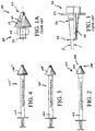
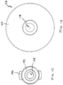
- One commercially available device commonly used for dispensing treatment fluid in substantially misted form includes the widely used white polypropylene actuator 50 illustrated in FIG. 1 .
- Such actuator is manufactured by a company known as Valois or Aptar and having a worldwide presence.
- the actuator is typically provided as an OEM component and is ubiquitously available in an assortment of spray-bottle, or pump-bottle applications. Although certain atomizing details are approximated or not illustrated, relevant external structure of the actuator 50 is illustrated substantially true to scale.
- Actuator 50 is exemplary of a discharge nozzle that is expressly not structured to resist over-insertion of the distal end into a nostril when applying topical therapy to nasal passages.
- the conic angle ⁇ calculated using direct measurements of a purchased actuator is about 3-1/2 degrees, and the nozzle tip is located more than 1 inch from the oblong cantilevered trigger structure 52 on which a user's fingers rest to actuate a fluid-dispensing pump bottle.
- the tip diameter 54 is about 0.3 inches, and the diameter 56 at the interference ring is about 0.41 inches.
- the interference ring is spaced apart from the tip by about 0.9 inches.
- Such slender, and small diameter, protruding structure can easily be over-inserted into an adult nostril, and cause damage to sensitive nasal tissue.
- Actuator 50 is also exemplary of a commercially available 2-piece atomizing nozzle.
- the internal distal surface of bore 558 is believed to carry turbine structure effective to apply a spin to fluid prior to expelling the fluid through a discharge orifice.
- a core element (not illustrated) forms a proximal surface for a turbine chamber.
- the core element is installed in a press-fit inside bore 58. Fluid is believed to flow distally along the side of the solid core element to the turbine chamber.
- a fluid supply conduit from a pump bottle can be placed in fluid communication with the proximal end of bore 58 (typically with a press-fit installation), to introduce treatment fluid to bore 58.
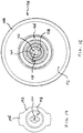
- Atomizer assembly 60 An exemplary 6-piece atomizer assembly adapted for use in nasal therapy is generally indicated at 60 in FIG. 1A .
- Such atomizer assembly is commercially available under part name MAD Nasal, MAD 300 from Wolfe Tory Medical, Inc., having a place of business located at 79 West 4500 South, Suite 18, Salt Lake City, UT 84107.
- Atomizer assembly 60 includes atomizing nozzle, generally 62, affixed to a short extension conduit 64.
- a malleable wire is installed in one of two lumen that extend lengthwise through the conduit.
- a separate fluid guidance structure (not illustrated) is trapped inside the nozzle tip shell upon assembly of the nozzle tip shell and extension conduit.
- Luer-locking structure generally 66, including torsion wings 68 and thread 70, is affixed to the proximal end of conduit 64.
- the nozzle 62 and extension conduit 64 are forced into a soft rubber nasal stopper 72.
- US 2005/0131357 discloses a combination of a stem and a nasal stopper being operable as an atomizing nozzle. It would be an improvement to provide a 2-piece atomizer having integral structure of a discharge tip configured to permit insertion of a distal tip end into even a child's nostril, and to resist over-insertion of the tip end into other nostrils having a range in larger size. A further advance would provide a 2-piece atomizer including integral threaded luer connection structure. Another advance would provide an atomizing nozzle having a minimized dead volume to promote efficient use, and reduce waste, of treatment fluids.
- the invention is defined by claim 1.
- an operable atomizing nozzle that can be formed from only two pieces: a nasal stopper, and a stem. That is, a combination consisting of only the stem and the nasal stopper is operable as an atomizing nozzle.
- the atomizing nozzle is typically structured for use in combination with a syringe.
- a distal end of the nasal stopper includes a protruding tip that carries a discharge orifice for dispensing treatment fluids in misted, or atomized, form.
- a preferred such tip is sufficiently small in cross-section as to permit entrance of the tip into a nostril opening of a human child.
- the leading end of the tip is structured to be blunt to avoid causing tissue damage inside a nostril.
- the trailing end of a tip is typically structured to suggest a cylindrical section, a length of the cylindrical section being sized to form an interference with structure of a nostril to resist transverse displacement of the tip from an inserted position inside the nostril.
- a proximal portion of the nasal stopper is configured to resist over-insertion of the protruding tip into a child's nostril opening.
- a currently preferred nasal stopper consists of a single unitary element.
- a currently preferred proximal portion may be characterized as a shield affixed to the protruding tip and arranged to define a flaring wall providing a variable diameter sized to contact skin around the opening of a plurality of different-sized nostrils effective to resist over-insertion of the distal portion of the nasal stopper.
- One workable shield includes a substantially conic surface, the conic angle being selected from a range between about 20 degrees and about 60 degrees. The currently preferred conic angle is about 30 degrees.
- a desirable shield comprises a substantially conic distally facing surface devoid of radial protrusions, with the proximal end of the conic surface being configured as a cantilevered free end.
- a workable stem extends in a length direction between a proximal end and a distal end and is configured to couple directly to the nasal stopper.
- the stem provides a lumen to conduct treatment fluid to the atomizing structure.
- a preferred stem consists of a single unitary element. Integral thread structure carried at the proximal end of the stem is typically configured to couple with a lure-locking portion of a syringe. Sometimes, the stem is sized in length such that, upon assembly of the atomizer, that thread structure is disposed inside a volume defined by the nasal stopper.
- a preferred stem is structured to require fluid to discharge in a radial direction from at least one side discharge opening disposed at a location proximal to the distal end of the stem.
- a workable connection is formed between a stem and a nasal stopper between first cooperating coupling structure configured to form a primary distal fluid seal to resist leakage of fluid from the lumen.
- a workable connection between a stem and nasal stopper may also include a second cooperating coupling structure configured to form a primary torsion-carrying connection.
- the combination formed by the nasal stopper and stem forms an atomizer including the aforementioned discharge orifice. That is, the discharge orifice is disposed in a wetted fluid path to conduct fluid from a turbine chamber of the atomizer.
- the stem is structured to provide a lumen for communication of treatment fluid to the turbine chamber for discharge of treatment fluid substantially as a mist from the discharge opening.
- a portion of the proximal wall of the turbine chamber is defined by structure disposed at a distal end of the stem.
- a filler piece may be installed within the lumen of the stem.
- a workable filler piece is structured to reduce dead volume inside the working portion of the atomizer, itself, to less than about 0.02 ml.
- An alternative workable filler piece is further structured to reduce dead volume inside a syringe that is connected to the atomizer assembly to the extent that the dead volume of the combination including the syringe and atomizer is less than about 0.03 ml.
- the dead volume in a combination including a syringe and atomizer is less than 0.02 ml.
- the dead volume in a combination including a syringe and atomizer is less than about 0.01 ml.
- the disclosure includes a method of, e.g ., nasal or other delivery comprising utilizing the described atomizing nozzle.
- the present invention provides an apparatus and method for applying treatment fluid to facilitate certain medical procedures.
- Preferred embodiments are used to apply topical treatment fluid in misted form to nasal passageways.
- atomize expelled fluid it is meant that the discharged fluid is dispersed substantially as a mist or cloud composed of very small droplets.
- Design variables incorporated in an atomizing nozzle include characteristic size of the discharge orifice, amount of pressure applied to the fluid upstream of the discharge orifice, and any turbine chamber structural arrangement to induce fluid spin. Effective atomization requires an expelled fluid to pass through a sufficient pressure drop at a discharge orifice. Further, the expelled fluid must have a rotational component of motion, (spin) about the discharge axis. Radial spread of the ejected cloud increases in correspondence with increases in the fluid spin rate at the discharge orifice.
- integral is used to mean referenced elements are formed from a single continuous piece of material.
- an assembly may provide the same functionality, or even include the same elements, but is formed from more than one piece of material.
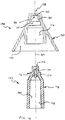
- a first currently preferred assembly for dispensing a treatment fluid is illustrated generally at 100 in FIG. 2 .
- Second and third currently preferred embodiments are indicated generally at 100' and 100", respectively, in FIGs. 3 and 4 . All three embodiments illustrated in FIGs. 2-4 are illustrated substantially at true scale with the attached syringes, and therefore convey a realistic sense of the visual appearance produced by such embodiments.
- the first embodiment 100 includes a fluid motive source 102, in combination with a dispensing nozzle, generally 104.
- the illustrated fluid motive source 102 in FIG. 1 is a 1 ml syringe, although other arrangements effective to cause pressure on a fluid are workable, including syringes having different fluid capacities.
- the illustrated dispensing nozzle 104 is a 2-piece fluid atomizing nozzle operable to eject treatment fluid as a mist or cloud. Such atomizing nozzles apply spin (about an ejection axis) to a fluid just prior to ejecting the fluid through a small diameter orifice. The discharged spinning fluid experiences a significant pressure drop across the exit orifice, and is thereby effectively atomized.
- Dispensing nozzle 104 includes a shield 106 structured to resist over-insertion of the distal end, generally 108, into nostril openings that may have different sizes.
- First and second alternative shields 106' and 106" constitute the principal differences in structure illustrated in FIGs. 1-3 .
- maximum sizes may be varied, as well as shape of the shields, including their trailing ends.
- the maximum diameter of shield 106 is 0.66 inches.
- the maximum diameter of shield 106' is about 0.8 inches, and the maximum diameter for shield 106" is about 0.75 inches.
- Currently preferred shield embodiments generally fall within such a range in maximum diameter.
- the trailing end of shield 106" is rounded by including a rearward projecting dogleg section. Such contouring can be more comfortable when pressed against the lip of a patient during administration of therapeutic fluids.
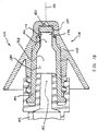
- currently preferred atomizers include a nasal stopper, generally 110, and a stem, generally 112.
- An exemplary stem cooperates with an exemplary nasal stopper to form an operational 2-piece atomizing nozzle.
- a currently preferred stem 112 carries integrated thread structure 113.
- a nasal stopper 110 includes a distally projecting tip 114, and a shield 116.
- the distally projecting tip 114 carries a discharge orifice, generally indicated at 118.
- the leading end 120 of tip 114 is desirably blunt, as illustrated, to avoid causing tissue damage inside a child's nostril.
- the cylindrical section it is desirable for the cylindrical section to provide a length "L" sufficient to form a structural interference with the opening of a nostril to resist accidental transverse displacement of tip 114 from an inserted position inside that nostril.
- a workable length "L" is about 0.1 inches, or so.
- the currently preferred distally protruding tip has a length "L" of 5 mm, or about 0.13 inches.
- the tip 114 is structured and sized to permit its insertion into a nostril opening of a child. That means, the diameter of the cylindrical portion of tip 114 is typically less than about 0.3 inches, with a currently preferred diameter being about 0.18 inches.
- a shield 116 it is preferred for a shield 116 to provide a proximal portion configured to resist over-insertion of discharge orifice 118 into a nasal opening.
- shield 116 defines a flaring wall providing a variable diameter sized to contact skin around the opening of a plurality of different-sized nostrils.
- illustrated shield 116 presents a substantially conic surface for contact with a nostril opening area.
- a shield is structured to provide a measure of centering and orienting to facilitate positioning discharge orifice 118 in a nasal cavity. While even a flat washer is workable, it should be realized that a too shallow conic angle permits over-insertion, and a too steep conic angle starts to loose self-centering ability.
- a workable conic angle may be selected from a range between a minimum value 126 of about 20 degrees (see shield 116'), and a maximum value 128 of about 60 degrees (see shield 116").
- the currently preferred shield 116 in FIG. 5 has a conic angle of 30 degrees and a maximum diameter "D" at proximal end 130 of about 0.66 inches.
- a preferred shield such as shield 116 in FIG. 5 , presents a smooth contact surface, which is devoid of radial protrusions, to the nostril and lip areas of a patient.
- the contact surface is structured to make a seal against skin at the nostril opening.
- the illustrated contact surface is formed by revolving a shape about a centerline.
- Such a smooth contact surface is in contrast to the oblong transverse trigger structure illustrated in FIG. 1 .
- the proximal end of a preferred contact surface is structured as a shell to provide an open cantilevered free end 132.
- Such cantilevered structure 132 is in contrast to the solid proximal surface of stopper 72 illustrated in FIG. 1A .
- a nostril opening of a human child is less than 0.3 inches in diameter.
- the dispensing tip of the atomizer illustrated in FIG. 1 simply cannot fit into a nostril of that child.
- a clinician places the dispensing end against the child's nasal opening, and hopes for sufficient alignment of the discharge orifice and nostril opening.
- One aspect of certain preferred embodiments of a nasal stopper 110 provides a protruding distal tip sized for reception inside the nostril of a child.
- proximal shield structure of the nasal stopper is configured to resist over-insertion of the protruding tip in the nostril of a child, as well as a large number of adults. It is recognized that certain adult nostrils may be sufficiently large that preferred nasal stoppers may not provide self-centering or seal against skin at the nasal opening. However, the currently preferred nasal stoppers are believed to work well with the vast majority of human nostrils.
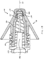
- FIGs. 6-11 illustrate externally visible details of the atomizing nozzle assembly 104 illustrated in FIG. 2 . Such FIGs. are illustrated in true scale, and therefore convey a realistic sense of the visual appearance produced by a currently preferred atomizer for nasal therapy.
- Nasal stopper 138 includes shield 106 with contact surface 140 configured to form a seal against skin at the nostril opening of a nostril selected from a plurality of nostrils having different sizes.
- Stem 142 couples with nasal stopper 138 to form a workable 2-piece atomizer assembly. As best illustrated in FIG. 9 , stem 142 is received in standoff 144. Integral thread structure, such as a plurality of thread lugs 146, is carried at a proximal end of stem 142.
- a 6% bore 148 is provided inside stem 142 to couple with the dispensing tip of a syringe and to conduct treatment fluid toward throat 150 for eventual discharge through discharge orifice 118.
- a volume 152 is defined by proximally open-ended skirt-like cantilevered shell structure of shield 106. One boundary of such volume is provided by plane 154 defined by structure at the proximal end of shield 106.
- FIGs. 12-15 illustrate certain cooperating internal structure of atomizing assembly 104.
- a distal end of stem 142 is configured to form anvil surface 156.
- anvil surface 156 is assembled to press against standoff surfaces 158, thereby defining a plurality of substantially fluid-tight turbine blades 160.
- fluid introduced through throat 150 is caused to pass through turbine blades 160 and subsequently enter turbine chamber 162.
- Fluid in turbine chamber 162 acquires a spin prior to being expelled through discharge orifice 118.
- anvil surfaces 156 is advanced along central axis 164 until that distal surface 156 encounters the cooperating proximal surface(s) of turbine structure, generally indicated at 166, disposed around a perimeter of conic turbine chamber 162.
- Turbine structure 166 includes a plurality of standoff surfaces 158 and turbine blades 160 best illustrated in FIG. 15 . Therefore, anvil surface 156 forms a portion of a proximal wall of turbine chamber 162.
- a primary fluid seal is formed between internal surface 170 of nasal stopper 138 and cooperating external surface 172 of stem 142.
- the primary fluid seal is disposed in close proximity to the one or more (two are illustrated) side discharge opening 174 disposed near the distal end of stem 142.
- a side discharge opening 174 provides a portion of the fluid path extending through stem 142 and causes a transverse component of velocity in fluid flowing there-through.
- the transverse component of travel is enforced at a location inside the fluid supply lumen and proximal to the distal end of stem 142.
- a preferred stem is structured to require fluid to discharge in a radial direction from at least one side discharge opening disposed at a location proximal to the distal end of that stem.
- a primary torsion-transfer coupling is created between internal surface 176 of nasal stopper 138 and a cooperating external surface 178 of stem 142.
- the contact area of the illustrated torsion-transfer coupling is larger than the contact area of the primary fluid seal.
- the radius extending to the torsion-carrying coupling is larger than the radius extending to the primary fluid seal surface. Therefore, the primary torsion-transfer coupling carries more torsion loading than the primary fluid seal surface.
- the cooperating elements that form a workable torsion-transfer coupling permit a user to grasp the contact surface 140 and impart twist to a nasal stopper 138 effective to install, and to remove, an atomizer onto luer-locking structure of a syringe, such as included at the distal end of syringe 102 in FIG. 18 .
- the primary fluid seal can operate as a secondary torsion-transfer coupling.
- the primary torsion-transfer coupling may function as a secondary fluid seal. It is currently preferred for both of the primary fluid seal and the primary torsion-coupling to be caused by an interference, or press-fit, between the cooperating elements. However, it is within contemplation that one or more such junction may be formed by alternative means, including adhesive joints, and the like. Also, it is within contemplation alternatively to provide a single surface at which to form a combined fluid seal and torsion-carrying coupling.
- the discharge end of a syringe 102 is conventionally jammed into compression against surface 180 of 6% bore 148 during engagement of cooperating luer-locking structure of syringe 102 and stem 142.
- Such an arrangement forms a fluid-tight coupling between the syringe 102 and stem 142.
- Treatment fluid flows from discharge bore 182, along unoccupied portion of the 6% bore 148, through throat 150, exits stem 142 through one or more side discharge opening 174, and then flows into liquid zone 184.
- the illustrated liquid zone 184 is essentially a cylindrical annulus about 0.015 inches in thickness and extending along axis 164 for a distance of about 0.1 inches.
- Fluid in liquid zone 184 is already displaced in a radial direction from the centerline axis 164 and enters openings of one or more turbine blade 160 (see FIG. 15 ). Fluid exits a turbine blade 160 into turbine chamber 162 with a spin. If sufficiently pressurized, fluid is then ejected through discharge orifice 118 as a mist.
- a dead volume may be defined as the volume of fluid remaining in a fluid transporting device subsequent to exhaustion of operable fluid pumping.
- Such dead volume for atomizer 104 includes the working portion (or portion unoccupied by syringe or other pumping device) of the 6% bore 148, throat 150, any side discharge openings 174, liquid zone 184, turbine blade(s) 160, and turbine chamber 162.
- the dead volume for a syringe 102 having a conventional plunger includes primarily the bore 182.
- the dead volume for the exemplary assembly 102/104 illustrated in FIG. 18 has been calculated to be about 0.102 ml, about half of which is contained in the syringe 102, and half in the atomizer 104. It is often desirable to minimize the dead volume, e.g. to reduce waste of treatment fluid when dispensing a single dose and subsequently discarding the dispensing device.
- One way to reduce dead volume in an atomizer assembly similar to assembly 104 is to reduce the length of the primary torsion-transfer coupling area, and neck down the distal portion of the 6% bore 148.
- it is possible to generate 600 psi with a 1 ml syringe 102 there is some danger of separation of a press-fit stem 142 from a nasal stopper 138 if the contact area is excessively reduced.
- FIG. 19 An alternative approach to reduce dead volume in an atomizer, such as atomizer assembly 104, is illustrated in FIG. 19 .
- a volume-reducing insert 190 may be installed in bore 148 and throat 150 to displace a substantial portion of dead volume within the atomizer 104.
- the lumen 148' essentially replaces the fluid conducting path previously provided by the unoccupied portion of the 6% bore 148 and throat 150, which constitutes the majority of the dead volume of an atomizer assembly 104.
- the remaining dead volume in the combination illustrated in FIG. 19 is less than about 0.07 ml.
- Preferred embodiments of the atomizer nozzle assembly itself, provide a small dead volume; including a dead volume of less than about 0.03 ml, less than about 0.02 ml, and even less than about 0.01 ml.
- the illustrated atomizer assembly 104 and insert 190 would have a dead volume of easily less than about 0.02 ml when used in combination with a syringe having a plunger configured to cause essentially zero dead volume within the syringe.
- a further reduction in dead volume of an assembly including a syringe 102 and atomizer assembly 104 may be effected by an arrangement such as illustrated in FIG. 20 .
- Volume-reducing insert 194 is installed in bore 148 and throat 150, and also projects proximally into bore 182 to displace a substantial portion of dead volume in the assembly formed by syringe 102 and atomizer 104.
- the lumen 148" essentially replaces the fluid conducting path previously provided by bore 182, the unoccupied portion of the 6% bore 148, and throat 150, which cause the majority of the dead volume of an assembly including syringe 102 and atomizer 104.
- the remaining dead volume in the illustrated embodiment in FIG. 20 is in the ballpark of about 0.02 ml.
- Preferred embodiments of an assembled combination of a nasal atomizing nozzle and syringe provide a small dead volume; including a dead volume of less than about 0.03 ml, less than about 0.02 ml, and even less than about 0.01 ml.
- FIG. 21 illustrates another embodiment of a 2-piece atomizer, generally indicated at 200.
- Atomizer 200 includes an integral protruding distal tip 202, integral stem 204, and integral shield 206.
- the integrated structure of the atomizer can require rather specialized tooling to manufacture by way of currently preferred injection molding. However, certain of such tooling permits integrated thread structure 113 to even be disposed within the volume defined by distally open-ended shield 206, as illustrated.
- Fluid guidance structure 208 provides the same functionality as the distal end of a stem 142, and distributes treatment fluid toward a liquid zone 184 ( e.g. see FIG. 18 ).
- One workable fluid guidance structure 208 is shown in cross-section in FIG. 22 .
- the illustrated fluid guidance structure 208 may be manufactured by cutting a length of extruded material to a desired length. The guidance structure208 may then be installed by press-fitting the cut length into an installed position. In such case, an outer radial dimension of ribs 210 is sized to cause a suitable press-fit engagement within the distal end of bore 180.
- Treatment fluid can then flow in the direction of central axis 164 between adjacent ribs 210 of an installed fluid guidance structure 208 and enter turbine chamber 162 by way of one or more turbine blade.
- the distal surface of guidance structure 208 forms an anvil surface equivalent to the anvil surface 156 of stem 142.
- a volume-reducing insert e.g. structured similar to insert 190 in FIG. 19 , may be installed to reduce dead volume inside an atomizer 200.
- a workable stem and/or stopper element is typically made from medical grade plastics, such as ABS, polypropylene, and polycarbonate.
- a workable spacer may be made from similar materials, or more compliant materials, such as rubber, urethane, and the like.
- Preferred assembly of a separate, or non-integral, stem to a stopper is accomplished with a press-fit joint between the elements.
- a radial interference of about 0.025 or 0.051 mm (0.001 or 0.002 inches) is workable to form a torsion-transfer coupling in polycarbonate elements structured similar to the embodiment illustrated in FIG. 18 .
- an adhesive joint may be used to joint a stem to a stopper.
- Workable adhesives are well known, and may be selected as appropriate for the material of composition of respective elements.
- polycarbonate materials may be bonded with cyclohexanone solvent adhesive.
- UV-curing adhesives may be used in some cases.
- a spacer is installed in a bore of an atomizer using a press-fit.
Landscapes
- Health & Medical Sciences (AREA)
- Engineering & Computer Science (AREA)
- Public Health (AREA)
- Life Sciences & Earth Sciences (AREA)
- Veterinary Medicine (AREA)
- Anesthesiology (AREA)
- Biomedical Technology (AREA)
- Heart & Thoracic Surgery (AREA)
- Hematology (AREA)
- General Health & Medical Sciences (AREA)
- Animal Behavior & Ethology (AREA)
- Bioinformatics & Cheminformatics (AREA)
- Otolaryngology (AREA)
- Pulmonology (AREA)
- Mechanical Engineering (AREA)
- Infusion, Injection, And Reservoir Apparatuses (AREA)
- Medicinal Preparation (AREA)
- Surgical Instruments (AREA)
Description
- The invention relates to atomizing nozzles and devices which dispense treatment fluids in a misted or dispersed, small particle size, form and to methods of their manufacture and use. Certain devices constructed according to the invention are particularly suitable for use in nasal therapy.
- Details of the principles of operation and construction of certain operable atomizing nozzles are disclosed in United States Patent
6,698,429 , titled "MEDICAL ATOMIZER", issued March 2, 2004, to Perry W. Croll, et al.. The principal focus of the '429 patent provides atomizing nozzles that may be inserted into, and advanced along the length of, conduit passages having cross-section areas of relatively small size. - One commercially available device commonly used for dispensing treatment fluid in substantially misted form includes the widely used white polypropylene actuator 50 illustrated in
FIG. 1 . Such actuator is manufactured by a company known as Valois or Aptar and having a worldwide presence. The actuator is typically provided as an OEM component and is ubiquitously available in an assortment of spray-bottle, or pump-bottle applications. Although certain atomizing details are approximated or not illustrated, relevant external structure of the actuator 50 is illustrated substantially true to scale. - Actuator 50 is exemplary of a discharge nozzle that is expressly not structured to resist over-insertion of the distal end into a nostril when applying topical therapy to nasal passages. In fact, the gradual taper and relatively small diameter of the extended discharge nozzle can easily permit over-insertion in an adult nostril. The conic angle γ calculated using direct measurements of a purchased actuator is about 3-1/2 degrees, and the nozzle tip is located more than 1 inch from the oblong cantilevered
trigger structure 52 on which a user's fingers rest to actuate a fluid-dispensing pump bottle. Thetip diameter 54 is about 0.3 inches, and thediameter 56 at the interference ring is about 0.41 inches. The interference ring is spaced apart from the tip by about 0.9 inches. Such slender, and small diameter, protruding structure can easily be over-inserted into an adult nostril, and cause damage to sensitive nasal tissue. - Actuator 50 is also exemplary of a commercially available 2-piece atomizing nozzle. The internal distal surface of bore 558 is believed to carry turbine structure effective to apply a spin to fluid prior to expelling the fluid through a discharge orifice. A core element (not illustrated) forms a proximal surface for a turbine chamber. The core element is installed in a press-fit inside
bore 58. Fluid is believed to flow distally along the side of the solid core element to the turbine chamber. A fluid supply conduit from a pump bottle can be placed in fluid communication with the proximal end of bore 58 (typically with a press-fit installation), to introduce treatment fluid to bore 58. - An exemplary 6-piece atomizer assembly adapted for use in nasal therapy is generally indicated at 60 in
FIG. 1A . Such atomizer assembly is commercially available under part name MAD Nasal, MAD 300 from Wolfe Tory Medical, Inc., having a place of business located at 79 West 4500 South, Suite 18, Salt Lake City, UT 84107.Atomizer assembly 60 includes atomizing nozzle, generally 62, affixed to ashort extension conduit 64. A malleable wire is installed in one of two lumen that extend lengthwise through the conduit. A separate fluid guidance structure (not illustrated) is trapped inside the nozzle tip shell upon assembly of the nozzle tip shell and extension conduit. Luer-locking structure, generally 66, including torsion wings 68 andthread 70, is affixed to the proximal end ofconduit 64. Thenozzle 62 andextension conduit 64 are forced into a soft rubbernasal stopper 72. -
US 2005/0131357 discloses a combination of a stem and a nasal stopper being operable as an atomizing nozzle. It would be an improvement to provide a 2-piece atomizer having integral structure of a discharge tip configured to permit insertion of a distal tip end into even a child's nostril, and to resist over-insertion of the tip end into other nostrils having a range in larger size. A further advance would provide a 2-piece atomizer including integral threaded luer connection structure. Another advance would provide an atomizing nozzle having a minimized dead volume to promote efficient use, and reduce waste, of treatment fluids. - The invention is defined by
claim 1. Provided is an operable atomizing nozzle that can be formed from only two pieces: a nasal stopper, and a stem. That is, a combination consisting of only the stem and the nasal stopper is operable as an atomizing nozzle. The atomizing nozzle is typically structured for use in combination with a syringe. - Desirably, a distal end of the nasal stopper includes a protruding tip that carries a discharge orifice for dispensing treatment fluids in misted, or atomized, form. A preferred such tip is sufficiently small in cross-section as to permit entrance of the tip into a nostril opening of a human child. Desirably, the leading end of the tip is structured to be blunt to avoid causing tissue damage inside a nostril. Also, the trailing end of a tip is typically structured to suggest a cylindrical section, a length of the cylindrical section being sized to form an interference with structure of a nostril to resist transverse displacement of the tip from an inserted position inside the nostril.
- A proximal portion of the nasal stopper is configured to resist over-insertion of the protruding tip into a child's nostril opening. A currently preferred nasal stopper consists of a single unitary element. A currently preferred proximal portion may be characterized as a shield affixed to the protruding tip and arranged to define a flaring wall providing a variable diameter sized to contact skin around the opening of a plurality of different-sized nostrils effective to resist over-insertion of the distal portion of the nasal stopper. One workable shield includes a substantially conic surface, the conic angle being selected from a range between about 20 degrees and about 60 degrees. The currently preferred conic angle is about 30 degrees. A desirable shield comprises a substantially conic distally facing surface devoid of radial protrusions, with the proximal end of the conic surface being configured as a cantilevered free end.
- A workable stem extends in a length direction between a proximal end and a distal end and is configured to couple directly to the nasal stopper. The stem provides a lumen to conduct treatment fluid to the atomizing structure. A preferred stem consists of a single unitary element. Integral thread structure carried at the proximal end of the stem is typically configured to couple with a lure-locking portion of a syringe. Sometimes, the stem is sized in length such that, upon assembly of the atomizer, that thread structure is disposed inside a volume defined by the nasal stopper. A preferred stem is structured to require fluid to discharge in a radial direction from at least one side discharge opening disposed at a location proximal to the distal end of the stem.
- A workable connection is formed between a stem and a nasal stopper between first cooperating coupling structure configured to form a primary distal fluid seal to resist leakage of fluid from the lumen. A workable connection between a stem and nasal stopper may also include a second cooperating coupling structure configured to form a primary torsion-carrying connection.
- The combination formed by the nasal stopper and stem forms an atomizer including the aforementioned discharge orifice. That is, the discharge orifice is disposed in a wetted fluid path to conduct fluid from a turbine chamber of the atomizer. The stem is structured to provide a lumen for communication of treatment fluid to the turbine chamber for discharge of treatment fluid substantially as a mist from the discharge opening. A portion of the proximal wall of the turbine chamber is defined by structure disposed at a distal end of the stem.
- Sometimes, a filler piece may be installed within the lumen of the stem. A workable filler piece is structured to reduce dead volume inside the working portion of the atomizer, itself, to less than about 0.02 ml. An alternative workable filler piece is further structured to reduce dead volume inside a syringe that is connected to the atomizer assembly to the extent that the dead volume of the combination including the syringe and atomizer is less than about 0.03 ml. In more preferred embodiments, the dead volume in a combination including a syringe and atomizer is less than 0.02 ml. In even more highly preferred embodiments, the dead volume in a combination including a syringe and atomizer is less than about 0.01 ml.
- The disclosure includes a method of, e.g., nasal or other delivery comprising utilizing the described atomizing nozzle.
- In the drawings, which illustrate what are currently regarded as the best modes for carrying out the invention:
-
FIG. 1 is a side view, partially in section, of a commercially available actuator; -
FIG 1A is a side view, partially in section, of a commercially available atomizing nozzle assembly adapted for nasal therapy; -
FIG. 2 is a side view, substantially to scale, of a first assembly; -
FIG. 3 is a side view, substantially to scale, of a second assembly; -
FIG. 4 is a side view, substantially to scale, of a third assembly; -
FIG. 5 is a side view, partially in section, of a superposition of a plurality of atomizing nozzles; -
FIG. 6 is a top view of the atomizer assembly illustrated inFIG. 2 ; -
FIG. 7 is a bottom view of the atomizer assembly illustrated inFIG. 2 ; -
FIG. 8 is a view in perspective from above of the atomizer assembly illustrated inFIG. 2 ; -
FIG. 9 is a view in perspective from below of the atomizer assembly illustrated inFIG. 2 ; -
FIG. 10 is a front view of the atomizer assembly illustrated inFIG. 2 ; -
FIG. 11 is a side view of the atomizer assembly illustrated inFIG. 2 ; -
FIG. 12 is a bottom view of a stem portion of the atomizer assembly illustrated inFIG. 2 ; -
FIG. 13 is a bottom view of a nasal stopper portion of the atomizer assembly illustrated inFIG. 2 ; -
FIG. 14 is a top view of the stem illustrated inFIG. 12 ; -
FIG. 15 is a top view of the nasal stopper illustrated inFIG. 13 ; -
FIG. 16 is an exploded front view in cross-section of a workable 2-piece atomizer assembly structured according to the invention; -
FIG. 17 is an exploded side view in cross-section of the assembly ofFIG. 16 ; -
FIG. 18 is an assembled view of the structure illustrated inFIG. 17 , installed on a syringe; -
FIG. 19 is a view similar toFIG. 18 , including alternative spacing structure to reduce dead volume inside the atomizer assembly; -
FIG. 20 is a view similar toFIG. 19 , including alternative spacing structure to reduce dead volume inside the atomizer assembly and syringe; -
FIG. 21 is a side view in cross-section of a workable 2-piece atomizer; and -
FIG. 22 is a cross-section view of the fluid guidance structure illustrated inFIG.21 . - The present invention provides an apparatus and method for applying treatment fluid to facilitate certain medical procedures. Preferred embodiments are used to apply topical treatment fluid in misted form to nasal passageways.
- Currently preferred fluid dispensing devices are adapted to atomize expelled treatment fluid. By "atomize expelled fluid", it is meant that the discharged fluid is dispersed substantially as a mist or cloud composed of very small droplets. Design variables incorporated in an atomizing nozzle include characteristic size of the discharge orifice, amount of pressure applied to the fluid upstream of the discharge orifice, and any turbine chamber structural arrangement to induce fluid spin. Effective atomization requires an expelled fluid to pass through a sufficient pressure drop at a discharge orifice. Further, the expelled fluid must have a rotational component of motion, (spin) about the discharge axis. Radial spread of the ejected cloud increases in correspondence with increases in the fluid spin rate at the discharge orifice.
- As used in this disclosure, the term "integral" is used to mean referenced elements are formed from a single continuous piece of material. In contrast, an assembly may provide the same functionality, or even include the same elements, but is formed from more than one piece of material.
- A first currently preferred assembly for dispensing a treatment fluid is illustrated generally at 100 in
FIG. 2 . Second and third currently preferred embodiments are indicated generally at 100' and 100", respectively, inFIGs. 3 and 4 . All three embodiments illustrated inFIGs. 2-4 are illustrated substantially at true scale with the attached syringes, and therefore convey a realistic sense of the visual appearance produced by such embodiments. - The
first embodiment 100 includes afluid motive source 102, in combination with a dispensing nozzle, generally 104. The illustratedfluid motive source 102 inFIG. 1 is a 1 ml syringe, although other arrangements effective to cause pressure on a fluid are workable, including syringes having different fluid capacities. A workable 1 ml syringe may currently be obtained from Becton Dickinson at WorldWideWeb://catalog.bd.com/bdCat/viewProduct.doCustomer?productNumber=309628. It is within contemplation alternatively to supply fluid from a pressurized or pre-pressurized canister, or pump bottle, and the like. - The illustrated
dispensing nozzle 104 is a 2-piece fluid atomizing nozzle operable to eject treatment fluid as a mist or cloud. Such atomizing nozzles apply spin (about an ejection axis) to a fluid just prior to ejecting the fluid through a small diameter orifice. The discharged spinning fluid experiences a significant pressure drop across the exit orifice, and is thereby effectively atomized.Dispensing nozzle 104 includes ashield 106 structured to resist over-insertion of the distal end, generally 108, into nostril openings that may have different sizes. - First and second
alternative shields 106' and 106", respectively, constitute the principal differences in structure illustrated inFIGs. 1-3 . As illustrated, maximum sizes may be varied, as well as shape of the shields, including their trailing ends. The maximum diameter ofshield 106 is 0.66 inches. The maximum diameter of shield 106' is about 0.8 inches, and the maximum diameter forshield 106" is about 0.75 inches. Currently preferred shield embodiments generally fall within such a range in maximum diameter. The trailing end ofshield 106" is rounded by including a rearward projecting dogleg section. Such contouring can be more comfortable when pressed against the lip of a patient during administration of therapeutic fluids. - With reference now to
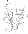
FIG. 5 , currently preferred atomizers include a nasal stopper, generally 110, and a stem, generally 112. An exemplary stem cooperates with an exemplary nasal stopper to form an operational 2-piece atomizing nozzle. A currently preferredstem 112 carriesintegrated thread structure 113. - Desirably, a
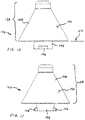
nasal stopper 110 includes adistally projecting tip 114, and ashield 116. Thedistally projecting tip 114 carries a discharge orifice, generally indicated at 118. Theleading end 120 oftip 114 is desirably blunt, as illustrated, to avoid causing tissue damage inside a child's nostril. It is currently preferred for the trailingend 122 oftip 114 to be structured to suggest a cylindrical section. Furthermore, it is desirable for the cylindrical section to provide a length "L" sufficient to form a structural interference with the opening of a nostril to resist accidental transverse displacement oftip 114 from an inserted position inside that nostril. A workable length "L" is about 0.1 inches, or so. The currently preferred distally protruding tip has a length "L" of 5 mm, or about 0.13 inches. Desirably, thetip 114 is structured and sized to permit its insertion into a nostril opening of a child. That means, the diameter of the cylindrical portion oftip 114 is typically less than about 0.3 inches, with a currently preferred diameter being about 0.18 inches. - With continued reference to
FIG. 5 , it is preferred for ashield 116 to provide a proximal portion configured to resist over-insertion ofdischarge orifice 118 into a nasal opening. As illustrated,shield 116 defines a flaring wall providing a variable diameter sized to contact skin around the opening of a plurality of different-sized nostrils. Although other shapes are workable, illustratedshield 116 presents a substantially conic surface for contact with a nostril opening area. Desirably, a shield is structured to provide a measure of centering and orienting to facilitatepositioning discharge orifice 118 in a nasal cavity. While even a flat washer is workable, it should be realized that a too shallow conic angle permits over-insertion, and a too steep conic angle starts to loose self-centering ability. A workable conic angle may be selected from a range between aminimum value 126 of about 20 degrees (see shield 116'), and amaximum value 128 of about 60 degrees (seeshield 116"). The currently preferredshield 116 inFIG. 5 has a conic angle of 30 degrees and a maximum diameter "D" atproximal end 130 of about 0.66 inches. - A preferred shield, such as
shield 116 inFIG. 5 , presents a smooth contact surface, which is devoid of radial protrusions, to the nostril and lip areas of a patient. Desirably, the contact surface is structured to make a seal against skin at the nostril opening. Also, it is preferred to structure a shield to provide a self-centering capability to urge a discharge orifice away from a nasal wall. The illustrated contact surface is formed by revolving a shape about a centerline. Such a smooth contact surface is in contrast to the oblong transverse trigger structure illustrated inFIG. 1 . Further, the proximal end of a preferred contact surface is structured as a shell to provide an open cantileveredfree end 132. Suchcantilevered structure 132 is in contrast to the solid proximal surface ofstopper 72 illustrated inFIG. 1A . - It is realized that humans are variable in their sizes and conformation. For purpose of this disclosure, it will be assumed that a nostril opening of a human child is less than 0.3 inches in diameter. The dispensing tip of the atomizer illustrated in
FIG. 1 simply cannot fit into a nostril of that child. In practice, a clinician places the dispensing end against the child's nasal opening, and hopes for sufficient alignment of the discharge orifice and nostril opening. One aspect of certain preferred embodiments of anasal stopper 110 provides a protruding distal tip sized for reception inside the nostril of a child. Desirably, proximal shield structure of the nasal stopper is configured to resist over-insertion of the protruding tip in the nostril of a child, as well as a large number of adults. It is recognized that certain adult nostrils may be sufficiently large that preferred nasal stoppers may not provide self-centering or seal against skin at the nasal opening. However, the currently preferred nasal stoppers are believed to work well with the vast majority of human nostrils. -
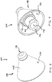
FIGs. 6-11 illustrate externally visible details of the atomizingnozzle assembly 104 illustrated inFIG. 2 . Such FIGs. are illustrated in true scale, and therefore convey a realistic sense of the visual appearance produced by a currently preferred atomizer for nasal therapy.Nasal stopper 138 includesshield 106 withcontact surface 140 configured to form a seal against skin at the nostril opening of a nostril selected from a plurality of nostrils having different sizes.Stem 142 couples withnasal stopper 138 to form a workable 2-piece atomizer assembly. As best illustrated inFIG. 9 , stem 142 is received instandoff 144. Integral thread structure, such as a plurality of thread lugs 146, is carried at a proximal end ofstem 142. It is within contemplation to extend alternative thread structure around a circumference ofstem 142. A 6% bore 148 is provided insidestem 142 to couple with the dispensing tip of a syringe and to conduct treatment fluid towardthroat 150 for eventual discharge throughdischarge orifice 118. Avolume 152 is defined by proximally open-ended skirt-like cantilevered shell structure ofshield 106. One boundary of such volume is provided byplane 154 defined by structure at the proximal end ofshield 106. -
FIGs. 12-15 illustrate certain cooperating internal structure of atomizingassembly 104. With reference toFIG. 12 , a distal end ofstem 142 is configured to formanvil surface 156. With reference toFIG. 15 ,anvil surface 156 is assembled to press against standoff surfaces 158, thereby defining a plurality of substantially fluid-tight turbine blades 160. Thus, fluid introduced throughthroat 150 is caused to pass throughturbine blades 160 and subsequently enterturbine chamber 162. Fluid inturbine chamber 162 acquires a spin prior to being expelled throughdischarge orifice 118. - With reference to
FIG. 16 , it can be visualized that anvil surfaces 156 is advanced alongcentral axis 164 until thatdistal surface 156 encounters the cooperating proximal surface(s) of turbine structure, generally indicated at 166, disposed around a perimeter ofconic turbine chamber 162.Turbine structure 166 includes a plurality of standoff surfaces 158 andturbine blades 160 best illustrated inFIG. 15 . Therefore,anvil surface 156 forms a portion of a proximal wall ofturbine chamber 162. - In the embodiment illustrated in
FIGs 16-18 , a primary fluid seal is formed betweeninternal surface 170 ofnasal stopper 138 and cooperatingexternal surface 172 ofstem 142. Desirably, the primary fluid seal is disposed in close proximity to the one or more (two are illustrated) side discharge opening 174 disposed near the distal end ofstem 142. Aside discharge opening 174 provides a portion of the fluid path extending throughstem 142 and causes a transverse component of velocity in fluid flowing there-through. Of note, the transverse component of travel is enforced at a location inside the fluid supply lumen and proximal to the distal end ofstem 142. In other words, a preferred stem is structured to require fluid to discharge in a radial direction from at least one side discharge opening disposed at a location proximal to the distal end of that stem. - A primary torsion-transfer coupling is created between
internal surface 176 ofnasal stopper 138 and a cooperatingexternal surface 178 ofstem 142. The contact area of the illustrated torsion-transfer coupling is larger than the contact area of the primary fluid seal. Further, the radius extending to the torsion-carrying coupling is larger than the radius extending to the primary fluid seal surface. Therefore, the primary torsion-transfer coupling carries more torsion loading than the primary fluid seal surface. The cooperating elements that form a workable torsion-transfer coupling permit a user to grasp thecontact surface 140 and impart twist to anasal stopper 138 effective to install, and to remove, an atomizer onto luer-locking structure of a syringe, such as included at the distal end ofsyringe 102 inFIG. 18 . - The primary fluid seal can operate as a secondary torsion-transfer coupling. Also, the primary torsion-transfer coupling may function as a secondary fluid seal. It is currently preferred for both of the primary fluid seal and the primary torsion-coupling to be caused by an interference, or press-fit, between the cooperating elements. However, it is within contemplation that one or more such junction may be formed by alternative means, including adhesive joints, and the like. Also, it is within contemplation alternatively to provide a single surface at which to form a combined fluid seal and torsion-carrying coupling.
- With reference now to
FIG. 18 (in which the syringe is not entirely to scale), the discharge end of asyringe 102 is conventionally jammed into compression againstsurface 180 of 6% bore 148 during engagement of cooperating luer-locking structure ofsyringe 102 andstem 142. Such an arrangement forms a fluid-tight coupling between thesyringe 102 andstem 142. Treatment fluid flows from discharge bore 182, along unoccupied portion of the 6% bore 148, throughthroat 150, exits stem 142 through one or moreside discharge opening 174, and then flows intoliquid zone 184. The illustratedliquid zone 184 is essentially a cylindrical annulus about 0.015 inches in thickness and extending alongaxis 164 for a distance of about 0.1 inches. Fluid inliquid zone 184 is already displaced in a radial direction from thecenterline axis 164 and enters openings of one or more turbine blade 160 (seeFIG. 15 ). Fluid exits aturbine blade 160 intoturbine chamber 162 with a spin. If sufficiently pressurized, fluid is then ejected throughdischarge orifice 118 as a mist. - With continued reference to
FIG. 18 , a dead volume may be defined as the volume of fluid remaining in a fluid transporting device subsequent to exhaustion of operable fluid pumping. Such dead volume foratomizer 104 includes the working portion (or portion unoccupied by syringe or other pumping device) of the 6% bore 148,throat 150, anyside discharge openings 174,liquid zone 184, turbine blade(s) 160, andturbine chamber 162. The dead volume for asyringe 102 having a conventional plunger includes primarily thebore 182. The dead volume for theexemplary assembly 102/104 illustrated inFIG. 18 has been calculated to be about 0.102 ml, about half of which is contained in thesyringe 102, and half in theatomizer 104. It is often desirable to minimize the dead volume, e.g. to reduce waste of treatment fluid when dispensing a single dose and subsequently discarding the dispensing device. - One way to reduce dead volume in an atomizer assembly similar to
assembly 104 is to reduce the length of the primary torsion-transfer coupling area, and neck down the distal portion of the 6% bore 148. However, because it is possible to generate 600 psi with a 1ml syringe 102, there is some danger of separation of a press-fit stem 142 from anasal stopper 138 if the contact area is excessively reduced. - An alternative approach to reduce dead volume in an atomizer, such as
atomizer assembly 104, is illustrated inFIG. 19 . A volume-reducinginsert 190 may be installed inbore 148 andthroat 150 to displace a substantial portion of dead volume within theatomizer 104. The lumen 148' essentially replaces the fluid conducting path previously provided by the unoccupied portion of the 6% bore 148 andthroat 150, which constitutes the majority of the dead volume of anatomizer assembly 104. The remaining dead volume in the combination illustrated inFIG. 19 is less than about 0.07 ml. Preferred embodiments of the atomizer nozzle assembly, itself, provide a small dead volume; including a dead volume of less than about 0.03 ml, less than about 0.02 ml, and even less than about 0.01 ml. The illustratedatomizer assembly 104 and insert 190 would have a dead volume of easily less than about 0.02 ml when used in combination with a syringe having a plunger configured to cause essentially zero dead volume within the syringe. - A further reduction in dead volume of an assembly including a
syringe 102 andatomizer assembly 104 may be effected by an arrangement such as illustrated inFIG. 20 . Volume-reducinginsert 194 is installed inbore 148 andthroat 150, and also projects proximally intobore 182 to displace a substantial portion of dead volume in the assembly formed bysyringe 102 andatomizer 104. Thelumen 148" essentially replaces the fluid conducting path previously provided bybore 182, the unoccupied portion of the 6% bore 148, andthroat 150, which cause the majority of the dead volume of anassembly including syringe 102 andatomizer 104. The remaining dead volume in the illustrated embodiment inFIG. 20 is in the ballpark of about 0.02 ml. Preferred embodiments of an assembled combination of a nasal atomizing nozzle and syringe provide a small dead volume; including a dead volume of less than about 0.03 ml, less than about 0.02 ml, and even less than about 0.01 ml. -
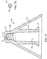
FIG. 21 illustrates another embodiment of a 2-piece atomizer, generally indicated at 200.Atomizer 200 includes an integral protrudingdistal tip 202,integral stem 204, andintegral shield 206. The integrated structure of the atomizer can require rather specialized tooling to manufacture by way of currently preferred injection molding. However, certain of such tooling permits integratedthread structure 113 to even be disposed within the volume defined by distally open-endedshield 206, as illustrated. - Workable turbine structure carried internal to
distal tip 202 is equivalent to theturbine structure 166 inFIG. 15 .Fluid guidance structure 208 provides the same functionality as the distal end of astem 142, and distributes treatment fluid toward a liquid zone 184 (e.g. seeFIG. 18 ). One workablefluid guidance structure 208 is shown in cross-section inFIG. 22 . The illustratedfluid guidance structure 208 may be manufactured by cutting a length of extruded material to a desired length. The guidance structure208 may then be installed by press-fitting the cut length into an installed position. In such case, an outer radial dimension ofribs 210 is sized to cause a suitable press-fit engagement within the distal end ofbore 180. Treatment fluid can then flow in the direction ofcentral axis 164 betweenadjacent ribs 210 of an installedfluid guidance structure 208 and enterturbine chamber 162 by way of one or more turbine blade. The distal surface ofguidance structure 208 forms an anvil surface equivalent to theanvil surface 156 ofstem 142. If desired, a volume-reducing insert (e.g. structured similar to insert 190 inFIG. 19 ), may be installed to reduce dead volume inside anatomizer 200. - It is currently preferred to manufacture elements such as a stem, stopper, and spacer, by injection molding. A workable stem and/or stopper element is typically made from medical grade plastics, such as ABS, polypropylene, and polycarbonate. A workable spacer may be made from similar materials, or more compliant materials, such as rubber, urethane, and the like. Preferred assembly of a separate, or non-integral, stem to a stopper is accomplished with a press-fit joint between the elements. A radial interference of about 0.025 or 0.051 mm (0.001 or 0.002 inches) is workable to form a torsion-transfer coupling in polycarbonate elements structured similar to the embodiment illustrated in
FIG. 18 . For similar elements made from polypropylene, the radial interference should be increased to about 0.102 mm (0.004 inches). In alternative construction, an adhesive joint may be used to joint a stem to a stopper. Workable adhesives are well known, and may be selected as appropriate for the material of composition of respective elements. For example, polycarbonate materials may be bonded with cyclohexanone solvent adhesive. UV-curing adhesives may be used in some cases. Preferably, a spacer is installed in a bore of an atomizer using a press-fit. - After having been apprised of the instant disclosure, one of ordinary skill in the art will be readily able to make the disclosed structure using commercially available materials and tools.
Claims (12)
- An apparatus comprising:a fluid discharge orifice defined in a distal end of a nasal stopper (138), the distal end being sufficiently small in cross-section as to permit entrance of the discharge orifice (174) into a nostril opening of a human child, a proximal portion of the nasal stopper comprising a shield (106) configured to resist over-insertion of the discharge orifice into the opening; anda stem (142) structured to provide a lumen for communication of treatment fluid to a turbine chamber for discharge of the fluid substantially as a mist from the discharge opening, the stem extending in a length direction between a proximal end and a distal end, the nasal stopper being affixed to the distal end of the stem; whereina thread structure (146) carried at the proximal end of the stem is configured to couple with a luer-locking portion of a syringe; and wherein the combination of the stem assembled to the nasal stopper is operable as an atomising nozzle, the atomising nozzle comprising the discharge orifice, the discharge orifice being disposed in a wetted fluid path to conduct fluid from the turbine chamber (162);wherein a first cooperating coupling structure (170, 172) is carried between the stem and the nasal stopper which is configured to form a distal fluid seal to resist leakage of fluid from the lumen; andwherein second cooperating coupling structure (176, 178) is carried between the stem and the nasal stopper is configured to form a primary torsion-carrying coupling; whereinthe stem is configured to couple with the nasal stopper; anda portion of a proximal wall of the turbine chamber is defined by a structure (156) disposed at a distal end of the stem to assist in discharge of the treatment fluid in misted, or atomised, form.
- The apparatus of claim 1, wherein:
the stem is sized in length such that, upon assembly of the apparatus, the thread structure is disposed inside a volume defined by the stopper. - The apparatus of claim 1 or 2, wherein:the stem consists of a single unitary element; andthe nasal stopper consists of a single unitary element.
- The apparatus of any preceding claim, wherein the nasal stopper is configured to define:
a distally projecting tip carrying the discharge orifice, the tip being structured and sized to permit insertion of the tip into the nostril opening, the leading end of the tip being blunt to avoid causing tissue damage inside a nostril, the trailing end of the tip being structured to suggest a cylindrical section, a length of the cylindrical section being sized to form an interference with structure of the nostril to resist transverse displacement of the tip from an inserted position inside the nostril; and wherein:
the shield is affixed to the tip and arranged to define a flaring wall providing a variable diameter sized to contact skin around the opening of a plurality of different-sized nostrils effective to resist the over-insertion. - The apparatus of claim 4, wherein:
the shield comprises a substantially conic surface, the conic angle being selected from a range between about 20 degrees and about 60 degrees. - The apparatus of claim 5, wherein the conic angle is about 30 degrees.
- The apparatus of claim 5, wherein the shield comprises a substantially conic distally facing surface devoid of radial protrusions, the proximal end of the conic surface being configured as a cantilevered free end.
- The apparatus of any preceding claim, wherein:
the stem is structured to require fluid to discharge in a radial direction from at least one side discharge opening disposed at a location proximal to the distal end of the stem. - The apparatus of any preceding claim, further comprising:
a filler piece received in the lumen of the stem and structured to reduce dead volume inside the apparatus to less than about 0.02 ml. - The apparatus of claim 9, wherein:
the filler piece is further structured to reduce dead volume inside a syringe that is connected to the apparatus to the extent that the dead volume of the assembly including the syringe and apparatus is less than about 0.03 ml. - The apparatus of any preceding claim, wherein:the stem is an integral part of the nasal stopper; anda portion of the proximal wall of the turbine chamber is defined by fluid guidance structure comprising a proximally oriented anvil surface disposed at least substantially in contact with standoff structure of the turbine chamber.
- The apparatus of claim 11, wherein:
the fluid guidance structure is configured and arranged to form a press-fit within cooperating lumen structure of the stem.
Priority Applications (1)
| Application Number | Priority Date | Filing Date | Title |
|---|---|---|---|
| EP17206026.1A EP3320935B1 (en) | 2010-11-12 | 2011-11-11 | Atomizer for nasal therapy |
Applications Claiming Priority (2)
| Application Number | Priority Date | Filing Date | Title |
|---|---|---|---|
| US45678010P | 2010-11-12 | 2010-11-12 | |
| PCT/IB2011/002809 WO2012063124A1 (en) | 2010-11-12 | 2011-11-11 | Atomizer for nasal therapy |
Related Child Applications (2)
| Application Number | Title | Priority Date | Filing Date |
|---|---|---|---|
| EP17206026.1A Division-Into EP3320935B1 (en) | 2010-11-12 | 2011-11-11 | Atomizer for nasal therapy |
| EP17206026.1A Division EP3320935B1 (en) | 2010-11-12 | 2011-11-11 | Atomizer for nasal therapy |
Publications (2)
| Publication Number | Publication Date |
|---|---|
| EP2637726A1 EP2637726A1 (en) | 2013-09-18 |
| EP2637726B1 true EP2637726B1 (en) | 2018-08-15 |
Family
ID=45401101
Family Applications (2)
| Application Number | Title | Priority Date | Filing Date |
|---|---|---|---|
| EP11799811.2A Active EP2637726B1 (en) | 2010-11-12 | 2011-11-11 | Atomizer for nasal therapy |
| EP17206026.1A Active EP3320935B1 (en) | 2010-11-12 | 2011-11-11 | Atomizer for nasal therapy |
Family Applications After (1)
| Application Number | Title | Priority Date | Filing Date |
|---|---|---|---|
| EP17206026.1A Active EP3320935B1 (en) | 2010-11-12 | 2011-11-11 | Atomizer for nasal therapy |
Country Status (11)
| Country | Link |
|---|---|
| US (2) | US11241547B2 (en) |
| EP (2) | EP2637726B1 (en) |
| JP (3) | JP2013543754A (en) |
| CN (2) | CN103298510B (en) |
| AU (2) | AU2011327848C1 (en) |
| BR (1) | BR112013012758A2 (en) |
| CA (2) | CA2817482C (en) |
| ES (2) | ES2694800T3 (en) |
| TR (1) | TR201815129T4 (en) |
| TW (1) | TWI569823B (en) |
| WO (1) | WO2012063124A1 (en) |
Families Citing this family (35)
| Publication number | Priority date | Publication date | Assignee | Title |
|---|---|---|---|---|
| CA2817482C (en) * | 2010-11-12 | 2018-10-30 | Wolfe Tory Medical, Inc. | Atomizer for nasal therapy |
| EP2484454B1 (en) * | 2011-02-02 | 2014-05-14 | Dispensys AG | Discharge device for flowable material |
| JP5992321B2 (en) * | 2012-12-27 | 2016-09-14 | 株式会社吉野工業所 | Syringe type ejection container |
| JP5944309B2 (en) * | 2012-12-27 | 2016-07-05 | 株式会社吉野工業所 | Syringe type ejection container |
| JP2015123297A (en) * | 2013-12-27 | 2015-07-06 | 株式会社吉野工業所 | Syringe-type ejection container |
| US9821126B2 (en) * | 2014-02-21 | 2017-11-21 | Neogen Corporation | Fluid atomizer, nozzle assembly and methods for assembling and utilizing the same |
| CA3012477C (en) * | 2016-02-04 | 2019-09-24 | Ip Med, Inc. | Medicament delivery device and method |
| WO2017201003A1 (en) * | 2016-05-17 | 2017-11-23 | Mayo Foundation For Medical Education And Research | Materials and methods for treating chronic cough |
| CN106178238A (en) * | 2016-08-08 | 2016-12-07 | 中山市美捷时包装制品有限公司 | A kind of nasal cavity inbalation administration device |
| CN106512156A (en) * | 2016-09-28 | 2017-03-22 | 苏州林华医疗器械股份有限公司 | Atomizer for nasal therapy |
| JP6558392B2 (en) * | 2017-04-04 | 2019-08-14 | ニプロ株式会社 | Syringe type ejection device |
| CN107198831B (en) * | 2017-07-01 | 2024-04-02 | 广东凯西欧照明有限公司 | A phototherapy for nasal congestion |
| US10617832B2 (en) | 2017-11-22 | 2020-04-14 | Southwest Research Institute | High precision, low dose atomizer |
| WO2019228946A1 (en) * | 2018-05-29 | 2019-12-05 | Shl Medical Ag | Assembly for spray device, spray device, medicament delivery device and method |
| CN108939225A (en) * | 2018-06-12 | 2018-12-07 | 陈新 | The universal larynx mouth of disposable nasal-suction type |
| US10688793B1 (en) * | 2019-02-26 | 2020-06-23 | Funai Electric Co., Ltd. | Fluidic dispensing apparatus and fluid dispensing cartridge therefor |
| JP7280965B2 (en) * | 2019-10-01 | 2023-05-24 | 東興薬品工業株式会社 | Nasal Spray/Injection Nozzles and Nasal Rest Products |
| WO2021077537A1 (en) * | 2019-10-25 | 2021-04-29 | 天津美迪斯医疗用品有限公司 | Nozzle type drug delivery device applied to airway products |
| US11890409B1 (en) * | 2019-11-19 | 2024-02-06 | Saeed Rezakhany | Methods of curing early stages of, and preventing, upper respiratory infections and applicators therefor |
| KR102901114B1 (en) * | 2019-12-18 | 2025-12-16 | 얀센 파마슈티카 엔브이 | Packaging systems and packaging kits for drug delivery devices |
| CN111265763A (en) * | 2020-03-19 | 2020-06-12 | 无锡普莱尔医疗科技有限公司 | Disposable nasal mucosa drug delivery device |
| IT202000003820U1 (en) * | 2020-07-01 | 2022-01-01 | Adl Farm S R L | "ENHANCED NASAL NEBULIZER" |
| EP4243901B1 (en) * | 2020-11-12 | 2025-06-18 | Hogne AB | Plug for insertion into the nose or ear of a subject for administering a fluid therapeutic agent |
| CN112472984B (en) * | 2020-12-15 | 2023-01-03 | 石家庄鑫富达医药包装有限公司 | Nasal cavity drug delivery device |
| CN112704783B (en) * | 2020-12-17 | 2021-09-14 | 中南大学 | Single-gas-source extrusion type gas-liquid coaxial impact atomizer |
| ES1270264Y (en) * | 2021-05-14 | 2021-09-29 | Baquero Gerard Delpuy | DOSING NOZZLE |
| CN113304386A (en) * | 2021-05-27 | 2021-08-27 | 苏州江镨健康科技有限公司 | Disposable self-destruction type nasal mucosa injector |
| CN113350634A (en) * | 2021-07-16 | 2021-09-07 | 丁要武 | Spray delivery device and spray delivery system comprising the same |
| USD987820S1 (en) * | 2021-07-19 | 2023-05-30 | Nipro Corporation | Medical atomizer for nasal cavity |
| GB202202890D0 (en) * | 2022-03-02 | 2022-04-13 | Consort Medical Ltd | Improvements relating to nasal pieces |
| CN115518243A (en) * | 2022-10-11 | 2022-12-27 | 苏州矽劼微电子有限公司 | an atomizing device |
| WO2024091453A1 (en) * | 2022-10-23 | 2024-05-02 | Gold Product Development, Inc. | Nasal spray positioning device |
| CN219271834U (en) * | 2023-02-06 | 2023-06-30 | 无锡耐思生命科技股份有限公司 | An atomizing nozzle and a nasal drug delivery device |
| WO2025003228A1 (en) * | 2023-06-27 | 2025-01-02 | Intervet International B.V. | Injection system |
| WO2025240756A1 (en) | 2024-05-15 | 2025-11-20 | Teleflex Medical Incorporated | Dose divider for a medical device |
Family Cites Families (69)
| Publication number | Priority date | Publication date | Assignee | Title |
|---|---|---|---|---|
| US3124959A (en) | 1964-03-17 | Primary differential pressure sensing | ||
| US2096831A (en) | 1936-05-28 | 1937-10-26 | Wappler Frederick Charles | Sterilizable pressure gauge |
| US2252874A (en) | 1938-11-04 | 1941-08-19 | Vischer Products Company | Pressure indicator |
| DE2609882C3 (en) | 1976-03-10 | 1982-12-16 | Hauser Verwaltungs-Gesellschaft Mbh, 6370 Oberursel | Fine pressure measuring device for particularly small measuring ranges |
| US4256099A (en) | 1979-03-21 | 1981-03-17 | Dryden Gale E | Two-tube resuscitation system |
| DE2945662A1 (en) | 1979-11-12 | 1981-05-21 | Hauser Verwaltungs-Gesellschaft Mbh, 6370 Oberursel | Vehicle oil level indicator - has light source on one side of pivoted indicator surface providing analogue display |
| US4445366A (en) | 1982-06-01 | 1984-05-01 | Carrier Corporation | Pressure differential gage and a method for detecting the presence of noncondensible gases in a refrigeration system |
| US4923448A (en) * | 1988-12-06 | 1990-05-08 | Mark Anderson | Syringe with spray nozzle tip |
| GB2229367A (en) | 1989-03-22 | 1990-09-26 | Archibald Ian Jeremy Brain | Artificial airway device |
| US5114415A (en) * | 1989-06-14 | 1992-05-19 | Susan Shedlock | Apparatus for suctioning secretions from upper airways |
| JP2922935B2 (en) * | 1989-08-11 | 1999-07-26 | 東興薬品工業株式会社 | Disposable adapter for nasal spray container for viscous liquid |
| US5237988A (en) | 1990-11-13 | 1993-08-24 | Mcneese Wesley G | Device for fastening an endotracheal tube |
| US5241956A (en) | 1992-05-21 | 1993-09-07 | Brain Archibald Ian Jeremy | Laryngeal mask airway with concentric drainage of oesophagus discharge |
| FR2692174B1 (en) * | 1992-06-16 | 1994-08-19 | Valois | Compressed gas device for projecting in finely divided form a single dose of a fluid substance. |
| US5443063A (en) | 1993-08-31 | 1995-08-22 | The Johns Hopkins University | Cuffed oro-pharyngeal airway |
| US5429600A (en) * | 1994-05-02 | 1995-07-04 | Heinke; Richard M. | Method for delivering a pharmaceutical into the nostril of an animal |
| JPH08547A (en) | 1994-06-23 | 1996-01-09 | Koushinshiya:Kk | Endoscope insertion guide |
| FR2736285B1 (en) * | 1995-07-07 | 1997-08-22 | Valois | DEVICE FOR DISPENSING FLUID PRODUCT WITH BACTERIOSTATIC ACTION |
| MY138519A (en) | 1995-10-03 | 2009-06-30 | Indian Ocean Medical Inc | Artificial airway device |
| US5609581A (en) * | 1995-10-11 | 1997-03-11 | Lawson Mardon Wheaton Inc. | Single dose medicament dispenser assembly |
| JP3503730B2 (en) | 1996-12-24 | 2004-03-08 | 住友ベークライト株式会社 | Emergency Resuscitation Esophageal Airway |
| US6079409A (en) | 1997-07-25 | 2000-06-27 | Brain; Archibald Ian Jeremy | Intubating laryngeal mask |
| JP3047521U (en) * | 1997-09-26 | 1998-04-14 | 前田産業株式会社 | Spray holder |
| US5935084A (en) | 1997-09-30 | 1999-08-10 | Johnson & Johnson Professional, Inc. | Inflatable pressure indicator |
| US6016800A (en) * | 1997-10-24 | 2000-01-25 | Century; Theodore J. | Intrapulmonary aerosolizer |
| DE19749514A1 (en) * | 1997-11-08 | 1999-05-12 | Pfeiffer Erich Gmbh & Co Kg | Delivery of a mixture of media for e.g. pharmaceutical products |
| FR2771296B1 (en) * | 1997-11-25 | 2000-03-10 | Sofab | NASAL TIP WITH END CLOSURE |
| US5899878A (en) * | 1998-06-24 | 1999-05-04 | Bradley Pharmaceuticals, Inc. | Nasal irrigation system |
| FR2782024B1 (en) * | 1998-08-04 | 2000-10-13 | Valois Sa | DISPENSING HEAD AND DEVICE FOR DISPENSING A FLUID PRODUCT COMPRISING SUCH A HEAD |
| US6112743A (en) * | 1998-09-04 | 2000-09-05 | Wolfe Tory Medical, Inc. | Connector for syringe and atomizer and the like |
| GB9821771D0 (en) | 1998-10-06 | 1998-12-02 | Brain Archibald Ian Jeremy | Improvements relating to laryngeal mask airway devices |
| US6631720B1 (en) | 1999-10-07 | 2003-10-14 | Archibald I. J. Brain | Laryngeal mask with large-bore gastric drainage |
| EP1092447B1 (en) * | 1999-10-14 | 2004-01-07 | Becton Dickinson and Company | Nasal delivery device including spray nozzle |
| US6213980B1 (en) * | 1999-10-26 | 2001-04-10 | Path | Fill facilitating unit dose injection cartridge and filling method |
| US6719752B2 (en) | 2000-08-31 | 2004-04-13 | Pentax Corporation | Endoscopic treatment instrument |
| US20020174865A1 (en) * | 2001-03-01 | 2002-11-28 | Gatton Brian M. | Nasal spray apparatus and system |
| US7021561B2 (en) * | 2001-12-18 | 2006-04-04 | Becton, Dickinson And Company | Spray device and method |
| US6698429B2 (en) | 2002-03-15 | 2004-03-02 | Wolfe Tory Medical, Inc. | Medical atomizer |
| GB0218868D0 (en) | 2002-08-14 | 2002-09-25 | Nasir Muhammed A | Improved airway management device |
| DE10239321B3 (en) * | 2002-08-27 | 2004-04-08 | Pari GmbH Spezialisten für effektive Inhalation | Aerosol therapy device |
| CN2579352Y (en) | 2002-11-26 | 2003-10-15 | 中国医学科学院中国协和医科大学整形外科医院 | Esophageal block type larynx cover ventilation path |
| RU2336910C2 (en) | 2003-04-11 | 2008-10-27 | Амбу А/С | Laryngoscopy mask and method of its manufacturing |
| AU2003904025A0 (en) | 2003-08-01 | 2003-08-14 | Baska, Kanag | Laryngeal mask |
| NZ545234A (en) | 2003-08-01 | 2008-11-28 | Kanag Baska | Laryngeal mask |
| US8210166B2 (en) * | 2003-12-16 | 2012-07-03 | Wolfe Tory Medical, Inc. | Vial multi-access adapter |
| JP4539974B2 (en) | 2004-10-05 | 2010-09-08 | 日本シャーウッド株式会社 | Tracheostomy tube |
| JP5009166B2 (en) | 2005-01-12 | 2012-08-22 | レスメド・リミテッド | Respirator with gusseted cushion |
| GB0510951D0 (en) | 2005-05-27 | 2005-07-06 | Laryngeal Mask Company The Ltd | Laryngeal mask airway device |
| EP1800706A1 (en) | 2005-12-22 | 2007-06-27 | Unomedical A/S | Laryngeal mask |
| CN2882657Y (en) | 2006-02-27 | 2007-03-28 | 天津市塑料研究所 | Double-tunnel plastic throat mask |
| GB0605669D0 (en) | 2006-03-21 | 2006-05-03 | Smiths Group Plc | Laryngeal mask assemblies |
| WO2007131267A1 (en) | 2006-05-12 | 2007-11-22 | Rlc Medical Pty Ltd | A restraining means for a tube |
| CN101057994B (en) | 2006-06-26 | 2011-09-14 | 株式会社佐多商会 | Laryngeal mask with guiding tube used for inserting stomach tube |
| US7895497B2 (en) | 2006-06-26 | 2011-02-22 | Samsung Electronics Co., Ltd. | Apparatus and method using reduced memory for channel decoding in a software-defined radio system |
| TW200803938A (en) * | 2006-07-07 | 2008-01-16 | Wei-Zheng Zhou | Spray apparatus for washing nasal cavity |
| US7900632B2 (en) | 2006-08-18 | 2011-03-08 | Cookgas, L.L.C. | Laryngeal mask with esophageal blocker and bite block |
| US7934502B2 (en) | 2007-05-11 | 2011-05-03 | Cookgas, Llc | Self-pressurizing supraglottic airway |
| GB2454199A (en) | 2007-10-30 | 2009-05-06 | Laryngeal Mask Co Ltd | Laryngeal mask with tape tab |
| US20090320852A1 (en) | 2008-06-27 | 2009-12-31 | Cuevas Brian J | Tracheostomy Tube Butterfly Flange |
| CH699987A1 (en) | 2008-11-27 | 2010-05-31 | Deltona Innovations Ag | Laryngeal mask with a nozzle. |
| GB0903654D0 (en) | 2009-03-03 | 2009-04-15 | Laryngeal Mask Company The Ltd | Artificial airway device |
| CN101991898A (en) | 2009-08-27 | 2011-03-30 | 住友电木株式会社 | Guide tube |
| FR2951441B1 (en) * | 2009-10-20 | 2012-06-01 | Valois Sas | DISPENSING HEAD FOR FLUID PRODUCT DISPENSING DEVICE. |
| CN201516220U (en) | 2009-11-11 | 2010-06-30 | 天津美迪斯医疗用品有限公司 | Built-in obstructed type gullet drainage tube laryngeal mask airway |
| US8343045B2 (en) | 2010-04-05 | 2013-01-01 | Intuitive Surgical Operations, Inc. | Curved cannula |
| CN201684261U (en) | 2010-04-15 | 2010-12-29 | 李明星 | Laryngeal mask for airway examination and treatment |
| ES2695043T3 (en) | 2010-10-15 | 2018-12-28 | Teleflex Life Sciences Unlimited Company | Artificial airway device |
| CA2817482C (en) * | 2010-11-12 | 2018-10-30 | Wolfe Tory Medical, Inc. | Atomizer for nasal therapy |
| EP3848078B1 (en) | 2011-10-31 | 2024-06-19 | Fisher & Paykel Healthcare Limited | Interface comprising a nasal sealing portion |
-
2011
- 2011-11-11 CA CA2817482A patent/CA2817482C/en active Active
- 2011-11-11 CN CN201180054374.6A patent/CN103298510B/en active Active
- 2011-11-11 AU AU2011327848A patent/AU2011327848C1/en active Active
- 2011-11-11 EP EP11799811.2A patent/EP2637726B1/en active Active
- 2011-11-11 CN CN201610349472.7A patent/CN106063963B/en active Active
- 2011-11-11 TW TW100141201A patent/TWI569823B/en active
- 2011-11-11 BR BR112013012758A patent/BR112013012758A2/en not_active IP Right Cessation
- 2011-11-11 US US13/884,576 patent/US11241547B2/en active Active
- 2011-11-11 ES ES11799811.2T patent/ES2694800T3/en active Active
- 2011-11-11 CA CA3016781A patent/CA3016781C/en active Active
- 2011-11-11 JP JP2013538286A patent/JP2013543754A/en active Pending
- 2011-11-11 EP EP17206026.1A patent/EP3320935B1/en active Active
- 2011-11-11 WO PCT/IB2011/002809 patent/WO2012063124A1/en not_active Ceased
- 2011-11-11 ES ES17206026T patent/ES2881328T3/en active Active
- 2011-11-11 TR TR2018/15129T patent/TR201815129T4/en unknown
-
2016
- 2016-08-11 AU AU2016213800A patent/AU2016213800B2/en active Active
- 2016-11-24 JP JP2016227655A patent/JP6433964B2/en active Active
-
2018
- 2018-07-05 JP JP2018128309A patent/JP2018187412A/en active Pending
-
2022
- 2022-02-07 US US17/666,099 patent/US20220233788A1/en active Pending
Non-Patent Citations (1)
| Title |
|---|
| None * |
Also Published As
| Publication number | Publication date |
|---|---|
| AU2016213800A1 (en) | 2016-09-01 |
| EP2637726A1 (en) | 2013-09-18 |
| US20220233788A1 (en) | 2022-07-28 |
| US11241547B2 (en) | 2022-02-08 |
| TWI569823B (en) | 2017-02-11 |
| WO2012063124A1 (en) | 2012-05-18 |
| US20130298902A1 (en) | 2013-11-14 |
| ES2881328T3 (en) | 2021-11-29 |
| ES2694800T3 (en) | 2018-12-27 |
| CA3016781A1 (en) | 2012-05-18 |
| CN103298510B (en) | 2016-06-29 |
| JP2017077478A (en) | 2017-04-27 |
| JP2018187412A (en) | 2018-11-29 |
| CA3016781C (en) | 2020-09-15 |
| TR201815129T4 (en) | 2018-11-21 |
| AU2011327848C1 (en) | 2016-10-20 |
| AU2016213800B2 (en) | 2018-05-31 |
| CN106063963B (en) | 2020-02-21 |
| AU2011327848A1 (en) | 2013-05-30 |
| AU2011327848B2 (en) | 2016-05-12 |
| JP2013543754A (en) | 2013-12-09 |
| CA2817482C (en) | 2018-10-30 |
| EP3320935B1 (en) | 2021-05-26 |
| CN106063963A (en) | 2016-11-02 |
| CN103298510A (en) | 2013-09-11 |
| TW201223571A (en) | 2012-06-16 |
| JP6433964B2 (en) | 2018-12-05 |
| CA2817482A1 (en) | 2012-05-18 |
| EP3320935A1 (en) | 2018-05-16 |
| BR112013012758A2 (en) | 2017-11-07 |
Similar Documents
| Publication | Publication Date | Title |
|---|---|---|
| US20220233788A1 (en) | Atomizer for nasal therapy | |
| EP2629820B1 (en) | Miniature fluid atomizer | |
| US8210166B2 (en) | Vial multi-access adapter | |
| JP2001509070A (en) | Discharge device for fluid medium using thrust piston pump | |
| WO1993003856A1 (en) | Topical sprayer with remotely actuated spray tip | |
| WO2018051371A2 (en) | Powder dispenser | |
| WO2003077975A1 (en) | Nasal spray apparatus and system | |
| WO2022003592A1 (en) | Improved nasal atomizer | |
| CN105194771A (en) | Small fluid atomizer | |
| CN206526355U (en) | Nose treats atomizer | |
| CN106512156A (en) | Atomizer for nasal therapy |
Legal Events
| Date | Code | Title | Description |
|---|---|---|---|
| PUAI | Public reference made under article 153(3) epc to a published international application that has entered the european phase |
Free format text: ORIGINAL CODE: 0009012 |
|
| 17P | Request for examination filed |
Effective date: 20130606 |
|
| AK | Designated contracting states |
Kind code of ref document: A1 Designated state(s): AL AT BE BG CH CY CZ DE DK EE ES FI FR GB GR HR HU IE IS IT LI LT LU LV MC MK MT NL NO PL PT RO RS SE SI SK SM TR |
|
| DAX | Request for extension of the european patent (deleted) | ||
| STAA | Information on the status of an ep patent application or granted ep patent |
Free format text: STATUS: EXAMINATION IS IN PROGRESS |
|
| 17Q | First examination report despatched |
Effective date: 20170209 |
|
| GRAP | Despatch of communication of intention to grant a patent |
Free format text: ORIGINAL CODE: EPIDOSNIGR1 |
|
| STAA | Information on the status of an ep patent application or granted ep patent |
Free format text: STATUS: GRANT OF PATENT IS INTENDED |
|
| INTG | Intention to grant announced |
Effective date: 20170802 |
|
| GRAJ | Information related to disapproval of communication of intention to grant by the applicant or resumption of examination proceedings by the epo deleted |
Free format text: ORIGINAL CODE: EPIDOSDIGR1 |
|
| STAA | Information on the status of an ep patent application or granted ep patent |
Free format text: STATUS: EXAMINATION IS IN PROGRESS |
|
| INTC | Intention to grant announced (deleted) | ||
| GRAP | Despatch of communication of intention to grant a patent |
Free format text: ORIGINAL CODE: EPIDOSNIGR1 |
|
| STAA | Information on the status of an ep patent application or granted ep patent |
Free format text: STATUS: GRANT OF PATENT IS INTENDED |
|
| INTG | Intention to grant announced |
Effective date: 20180223 |
|
| GRAS | Grant fee paid |
Free format text: ORIGINAL CODE: EPIDOSNIGR3 |
|
| GRAA | (expected) grant |
Free format text: ORIGINAL CODE: 0009210 |
|
| STAA | Information on the status of an ep patent application or granted ep patent |
Free format text: STATUS: THE PATENT HAS BEEN GRANTED |
|
| AK | Designated contracting states |
Kind code of ref document: B1 Designated state(s): AL AT BE BG CH CY CZ DE DK EE ES FI FR GB GR HR HU IE IS IT LI LT LU LV MC MK MT NL NO PL PT RO RS SE SI SK SM TR |
|
| REG | Reference to a national code |
Ref country code: AT Ref legal event code: REF Ref document number: 1029033 Country of ref document: AT Kind code of ref document: T Effective date: 20180815 Ref country code: GB Ref legal event code: FG4D Ref country code: CH Ref legal event code: EP |
|
| REG | Reference to a national code |
Ref country code: IE Ref legal event code: FG4D |
|
| REG | Reference to a national code |
Ref country code: DE Ref legal event code: R096 Ref document number: 602011051133 Country of ref document: DE |
|
| REG | Reference to a national code |
Ref country code: FR Ref legal event code: PLFP Year of fee payment: 8 |
|
| REG | Reference to a national code |
Ref country code: NL Ref legal event code: FP |
|
| REG | Reference to a national code |
Ref country code: LT Ref legal event code: MG4D |
|
| REG | Reference to a national code |
Ref country code: AT Ref legal event code: MK05 Ref document number: 1029033 Country of ref document: AT Kind code of ref document: T Effective date: 20180815 |
|
| PG25 | Lapsed in a contracting state [announced via postgrant information from national office to epo] |
Ref country code: SE Free format text: LAPSE BECAUSE OF FAILURE TO SUBMIT A TRANSLATION OF THE DESCRIPTION OR TO PAY THE FEE WITHIN THE PRESCRIBED TIME-LIMIT Effective date: 20180815 Ref country code: RS Free format text: LAPSE BECAUSE OF FAILURE TO SUBMIT A TRANSLATION OF THE DESCRIPTION OR TO PAY THE FEE WITHIN THE PRESCRIBED TIME-LIMIT Effective date: 20180815 Ref country code: FI Free format text: LAPSE BECAUSE OF FAILURE TO SUBMIT A TRANSLATION OF THE DESCRIPTION OR TO PAY THE FEE WITHIN THE PRESCRIBED TIME-LIMIT Effective date: 20180815 Ref country code: BG Free format text: LAPSE BECAUSE OF FAILURE TO SUBMIT A TRANSLATION OF THE DESCRIPTION OR TO PAY THE FEE WITHIN THE PRESCRIBED TIME-LIMIT Effective date: 20181115 Ref country code: LT Free format text: LAPSE BECAUSE OF FAILURE TO SUBMIT A TRANSLATION OF THE DESCRIPTION OR TO PAY THE FEE WITHIN THE PRESCRIBED TIME-LIMIT Effective date: 20180815 Ref country code: IS Free format text: LAPSE BECAUSE OF FAILURE TO SUBMIT A TRANSLATION OF THE DESCRIPTION OR TO PAY THE FEE WITHIN THE PRESCRIBED TIME-LIMIT Effective date: 20181215 Ref country code: NO Free format text: LAPSE BECAUSE OF FAILURE TO SUBMIT A TRANSLATION OF THE DESCRIPTION OR TO PAY THE FEE WITHIN THE PRESCRIBED TIME-LIMIT Effective date: 20181115 Ref country code: AT Free format text: LAPSE BECAUSE OF FAILURE TO SUBMIT A TRANSLATION OF THE DESCRIPTION OR TO PAY THE FEE WITHIN THE PRESCRIBED TIME-LIMIT Effective date: 20180815 Ref country code: GR Free format text: LAPSE BECAUSE OF FAILURE TO SUBMIT A TRANSLATION OF THE DESCRIPTION OR TO PAY THE FEE WITHIN THE PRESCRIBED TIME-LIMIT Effective date: 20181116 |
|
| PG25 | Lapsed in a contracting state [announced via postgrant information from national office to epo] |
Ref country code: HR Free format text: LAPSE BECAUSE OF FAILURE TO SUBMIT A TRANSLATION OF THE DESCRIPTION OR TO PAY THE FEE WITHIN THE PRESCRIBED TIME-LIMIT Effective date: 20180815 Ref country code: AL Free format text: LAPSE BECAUSE OF FAILURE TO SUBMIT A TRANSLATION OF THE DESCRIPTION OR TO PAY THE FEE WITHIN THE PRESCRIBED TIME-LIMIT Effective date: 20180815 Ref country code: LV Free format text: LAPSE BECAUSE OF FAILURE TO SUBMIT A TRANSLATION OF THE DESCRIPTION OR TO PAY THE FEE WITHIN THE PRESCRIBED TIME-LIMIT Effective date: 20180815 |
|
| PG25 | Lapsed in a contracting state [announced via postgrant information from national office to epo] |
Ref country code: RO Free format text: LAPSE BECAUSE OF FAILURE TO SUBMIT A TRANSLATION OF THE DESCRIPTION OR TO PAY THE FEE WITHIN THE PRESCRIBED TIME-LIMIT Effective date: 20180815 Ref country code: CZ Free format text: LAPSE BECAUSE OF FAILURE TO SUBMIT A TRANSLATION OF THE DESCRIPTION OR TO PAY THE FEE WITHIN THE PRESCRIBED TIME-LIMIT Effective date: 20180815 Ref country code: EE Free format text: LAPSE BECAUSE OF FAILURE TO SUBMIT A TRANSLATION OF THE DESCRIPTION OR TO PAY THE FEE WITHIN THE PRESCRIBED TIME-LIMIT Effective date: 20180815 Ref country code: PL Free format text: LAPSE BECAUSE OF FAILURE TO SUBMIT A TRANSLATION OF THE DESCRIPTION OR TO PAY THE FEE WITHIN THE PRESCRIBED TIME-LIMIT Effective date: 20180815 |
|
| REG | Reference to a national code |
Ref country code: DE Ref legal event code: R097 Ref document number: 602011051133 Country of ref document: DE |
|
| REG | Reference to a national code |
Ref country code: ES Ref legal event code: PC2A Owner name: TELEFLEX MEDICAL INCORPORATED Effective date: 20190513 |
|
| PG25 | Lapsed in a contracting state [announced via postgrant information from national office to epo] |
Ref country code: SK Free format text: LAPSE BECAUSE OF FAILURE TO SUBMIT A TRANSLATION OF THE DESCRIPTION OR TO PAY THE FEE WITHIN THE PRESCRIBED TIME-LIMIT Effective date: 20180815 Ref country code: SM Free format text: LAPSE BECAUSE OF FAILURE TO SUBMIT A TRANSLATION OF THE DESCRIPTION OR TO PAY THE FEE WITHIN THE PRESCRIBED TIME-LIMIT Effective date: 20180815 Ref country code: DK Free format text: LAPSE BECAUSE OF FAILURE TO SUBMIT A TRANSLATION OF THE DESCRIPTION OR TO PAY THE FEE WITHIN THE PRESCRIBED TIME-LIMIT Effective date: 20180815 |
|
| REG | Reference to a national code |
Ref country code: DE Ref legal event code: R082 Ref document number: 602011051133 Country of ref document: DE Representative=s name: MAUCHER JENKINS PATENTANWAELTE & RECHTSANWAELT, DE Ref country code: DE Ref legal event code: R081 Ref document number: 602011051133 Country of ref document: DE Owner name: TELEFLEX MEDICAL INCORPORATED, WAYNE, US Free format text: FORMER OWNER: WOLFE TORY MEDICAL, INC., SALT LAKE CITY, UTAH, US |
|
| PLBE | No opposition filed within time limit |
Free format text: ORIGINAL CODE: 0009261 |
|
| STAA | Information on the status of an ep patent application or granted ep patent |
Free format text: STATUS: NO OPPOSITION FILED WITHIN TIME LIMIT |
|
| REG | Reference to a national code |
Ref country code: NL Ref legal event code: PD Owner name: TELEFLEX MEDICAL INCORPORATED; US Free format text: DETAILS ASSIGNMENT: CHANGE OF OWNER(S), MERGE; FORMER OWNER NAME: WOLFE TORY MEDICAL, INC. Effective date: 20190614 |
|
| REG | Reference to a national code |
Ref country code: CH Ref legal event code: PL |
|
| 26N | No opposition filed |
Effective date: 20190516 |
|
| PG25 | Lapsed in a contracting state [announced via postgrant information from national office to epo] |
Ref country code: MC Free format text: LAPSE BECAUSE OF FAILURE TO SUBMIT A TRANSLATION OF THE DESCRIPTION OR TO PAY THE FEE WITHIN THE PRESCRIBED TIME-LIMIT Effective date: 20180815 Ref country code: LU Free format text: LAPSE BECAUSE OF NON-PAYMENT OF DUE FEES Effective date: 20181111 |
|
| REG | Reference to a national code |
Ref country code: GB Ref legal event code: 732E Free format text: REGISTERED BETWEEN 20190711 AND 20190717 |
|
| REG | Reference to a national code |
Ref country code: BE Ref legal event code: MM Effective date: 20181130 |
|
| REG | Reference to a national code |
Ref country code: IE Ref legal event code: MM4A |
|
| PG25 | Lapsed in a contracting state [announced via postgrant information from national office to epo] |
Ref country code: SI Free format text: LAPSE BECAUSE OF FAILURE TO SUBMIT A TRANSLATION OF THE DESCRIPTION OR TO PAY THE FEE WITHIN THE PRESCRIBED TIME-LIMIT Effective date: 20180815 Ref country code: CH Free format text: LAPSE BECAUSE OF NON-PAYMENT OF DUE FEES Effective date: 20181130 Ref country code: LI Free format text: LAPSE BECAUSE OF NON-PAYMENT OF DUE FEES Effective date: 20181130 |
|
| PG25 | Lapsed in a contracting state [announced via postgrant information from national office to epo] |
Ref country code: IE Free format text: LAPSE BECAUSE OF NON-PAYMENT OF DUE FEES Effective date: 20181111 |
|
| PG25 | Lapsed in a contracting state [announced via postgrant information from national office to epo] |
Ref country code: BE Free format text: LAPSE BECAUSE OF NON-PAYMENT OF DUE FEES Effective date: 20181130 |
|
| PG25 | Lapsed in a contracting state [announced via postgrant information from national office to epo] |
Ref country code: MT Free format text: LAPSE BECAUSE OF NON-PAYMENT OF DUE FEES Effective date: 20181111 |
|
| PGFP | Annual fee paid to national office [announced via postgrant information from national office to epo] |
Ref country code: ES Payment date: 20191202 Year of fee payment: 9 |
|
| PG25 | Lapsed in a contracting state [announced via postgrant information from national office to epo] |
Ref country code: PT Free format text: LAPSE BECAUSE OF FAILURE TO SUBMIT A TRANSLATION OF THE DESCRIPTION OR TO PAY THE FEE WITHIN THE PRESCRIBED TIME-LIMIT Effective date: 20180815 |
|
| PG25 | Lapsed in a contracting state [announced via postgrant information from national office to epo] |
Ref country code: HU Free format text: LAPSE BECAUSE OF FAILURE TO SUBMIT A TRANSLATION OF THE DESCRIPTION OR TO PAY THE FEE WITHIN THE PRESCRIBED TIME-LIMIT; INVALID AB INITIO Effective date: 20111111 Ref country code: MK Free format text: LAPSE BECAUSE OF NON-PAYMENT OF DUE FEES Effective date: 20180815 Ref country code: CY Free format text: LAPSE BECAUSE OF FAILURE TO SUBMIT A TRANSLATION OF THE DESCRIPTION OR TO PAY THE FEE WITHIN THE PRESCRIBED TIME-LIMIT Effective date: 20180815 |
|
| REG | Reference to a national code |
Ref country code: ES Ref legal event code: FD2A Effective date: 20220201 |
|
| PG25 | Lapsed in a contracting state [announced via postgrant information from national office to epo] |
Ref country code: ES Free format text: LAPSE BECAUSE OF NON-PAYMENT OF DUE FEES Effective date: 20201112 |
|
| P01 | Opt-out of the competence of the unified patent court (upc) registered |
Effective date: 20230621 |
|
| PGFP | Annual fee paid to national office [announced via postgrant information from national office to epo] |
Ref country code: NL Payment date: 20251126 Year of fee payment: 15 |
|
| PGFP | Annual fee paid to national office [announced via postgrant information from national office to epo] |
Ref country code: DE Payment date: 20251128 Year of fee payment: 15 |
|
| PGFP | Annual fee paid to national office [announced via postgrant information from national office to epo] |
Ref country code: GB Payment date: 20251127 Year of fee payment: 15 |
|
| PGFP | Annual fee paid to national office [announced via postgrant information from national office to epo] |
Ref country code: IT Payment date: 20251119 Year of fee payment: 15 |
|
| PGFP | Annual fee paid to national office [announced via postgrant information from national office to epo] |
Ref country code: FR Payment date: 20251125 Year of fee payment: 15 |
|
| PGFP | Annual fee paid to national office [announced via postgrant information from national office to epo] |
Ref country code: TR Payment date: 20251023 Year of fee payment: 15 |