EP2636956A1 - An oven door for a cooking oven and a method for preparing an oven door for a cooking oven - Google Patents
An oven door for a cooking oven and a method for preparing an oven door for a cooking oven Download PDFInfo
- Publication number
- EP2636956A1 EP2636956A1 EP12158271.2A EP12158271A EP2636956A1 EP 2636956 A1 EP2636956 A1 EP 2636956A1 EP 12158271 A EP12158271 A EP 12158271A EP 2636956 A1 EP2636956 A1 EP 2636956A1
- Authority
- EP
- European Patent Office
- Prior art keywords
- oven
- door
- hinge portion
- oven door
- hinge
- Prior art date
- Legal status (The legal status is an assumption and is not a legal conclusion. Google has not performed a legal analysis and makes no representation as to the accuracy of the status listed.)
- Granted
Links
- 238000010411 cooking Methods 0.000 title claims abstract description 59
- 238000000034 method Methods 0.000 title claims abstract description 24
- 239000003292 glue Substances 0.000 claims description 8
- XUIMIQQOPSSXEZ-UHFFFAOYSA-N Silicon Chemical compound [Si] XUIMIQQOPSSXEZ-UHFFFAOYSA-N 0.000 claims description 7
- 229910052710 silicon Inorganic materials 0.000 claims description 7
- 239000010703 silicon Substances 0.000 claims description 7
- 239000002184 metal Substances 0.000 claims description 5
- 238000004026 adhesive bonding Methods 0.000 claims description 2
- 229920003023 plastic Polymers 0.000 claims description 2
- 239000004033 plastic Substances 0.000 claims description 2
- 239000000463 material Substances 0.000 description 3
- 238000005260 corrosion Methods 0.000 description 2
- 230000007797 corrosion Effects 0.000 description 2
- 239000011521 glass Substances 0.000 description 2
- 238000012986 modification Methods 0.000 description 2
- 230000004048 modification Effects 0.000 description 2
- 239000000853 adhesive Substances 0.000 description 1
- 230000001070 adhesive effect Effects 0.000 description 1
- 230000000694 effects Effects 0.000 description 1
- 238000004519 manufacturing process Methods 0.000 description 1
- 239000002861 polymer material Substances 0.000 description 1
Images



Classifications
-
- F—MECHANICAL ENGINEERING; LIGHTING; HEATING; WEAPONS; BLASTING
- F24—HEATING; RANGES; VENTILATING
- F24C—DOMESTIC STOVES OR RANGES ; DETAILS OF DOMESTIC STOVES OR RANGES, OF GENERAL APPLICATION
- F24C15/00—Details
- F24C15/02—Doors specially adapted for stoves or ranges
- F24C15/023—Mounting of doors, e.g. hinges, counterbalancing
Definitions
- the present invention relates to an oven door for a cooking oven according to the preamble of claim 1.
- the present invention relates to a swing oven door for a cooking oven.
- the present invention relates to a method for preparing an oven door for a cooking oven according to the preamble of claim 11.
- the present invention relates to a cooking oven.
- An oven door in particular a swing oven door is attached at a cooking oven by one or more hinges.
- the hinges are visible or not visible.
- the hinges are made of metal and fastened at the door structure by screws, rivets or similar fixing elements. The assembling of the hinges at the door structure takes a lot of time. Further, corrosion problems may occur at the metal hinges. Moreover, it is expensive to adapt the colour of the hinges to the design of the oven door and the cooking oven.
- WO 2010/132057 A1 discloses an oven door pivotable around a horizontal axis.
- the oven door includes a glass panel, on which fittings are glued. Said fitting are provided for being connected to a hinge portion of a hinge for the oven door.
- the connection between the oven door and the oven is relative complex.
- the object of the present invention is achieved by the oven door for a cooking oven according to claim 1.
- the at least one first hinge portion is glued at the door panel.
- the at least one counter hinge portion is connectable to the cooking oven by another arbitrary method. Since the hinge portion is directly glued at the door panel, no additional parts are required.
- the hinge portion can be glued to the door panel by an automatic system and/or an automatic procedure.
- the properties of the door panel and the hinge portions are independent of each other.
- the door panel and the central hinge portion are interchangeable. Thus, an arbitrary number of different oven doors may be assembled by the same automatic system and/or procedure.
- the at least one second hinge portion may be detachably or permanently fixable or fixed at the cooking oven.
- the at least one second hinge portion is fixable or fixed at a side wall frame of the cooking oven by screws and/or rivets.
- the at least one first hinge portion is glued at the door panel by a silicon glue.
- the at least one first hinge portion is glued at a door frame supporting one or more door panels.
- At least one of the first hinge portion and the second hinge portion may be made of plastics. This prevents or restricts corrosion problems.
- the hinge is arranged behind the oven door or the door panel of said oven door, when the oven door is in a closed state. This arrangement is advantageous for the design of the cooking oven.
- the hinge may comprise a mechanical stop for limiting an aperture angle between the oven door and the cooking oven.
- a pivoting axis of the hinge extends along a vertical direction.
- first hinge portion and the second hinge portion may be made of metal.
- the object of the present invention is further achieved by the method for preparing an oven door for a cooking oven according to claim 11.
- the at least one first hinge portion is glued at the door panel.
- the hinge portion is directly glued at the door panel, so that no additional parts are required.
- the hinge portion can be glued to the door panel by an automatic system and/or an automatic procedure.
- an arbitrary number of different oven doors may be assembled by the same automatic system and/or procedure.
- the gluing of the at least one first hinge portion at the door panel is performed by an automatic procedure. This reduces the production time.
- the method is provided for preparing the oven door mentioned above.
- the present invention relates to a cooking oven including at least one oven door, in particular at least one swing oven door mentioned above.
- the oven is a built-in type oven, i.e. an oven structured and dimensioned so as to be mounted into a cavity of a furniture article.
- FIG 1 illustrates a front view of an oven door 10 at a cooking oven 12 according to a preferred embodiment of the present invention.
- the oven door 10 is in a closed state and arranged at a front side of the cooking oven 12. Further, an upper front panel 14 is also arranged at the front side of the cooking oven 12. The upper front panel 14 is arranged above the oven door 10.
- the oven door 10 is a swing oven door pivotable around a vertical axis.
- said vertical axis is on the left hand side of the oven door.
- the oven door 10 comprises a corresponding vertical hinge 20 at the left hand side.
- the hinge 20 is arranged at the rear side of the oven door 10, such that, when the oven door is mounted on a built-in type oven, and the oven is, in turn, mounted into a cavity of a furniture article, said hinge 20 is not visible in the closed state of said oven door 10.
- the oven door 10 comprises a window 16.
- the window 16 is arranged in the central portion of the oven door 10.
- the oven door 10 comprises two screw holes 18 provided for fixing a door handle.
- the screw holes 18 are arranged on the right hand side of the oven door 10.
- FIG 2 illustrates a perspective rear view of the oven door 10 for the cooking oven 12 according to the preferred embodiment of the present invention.
- the oven door 10 includes a door panel 32 and the hinge 20.
- FIG 2 clarifies the arrangement of the hinge 20 at the door panel 32 of the oven door 10.
- the hinge 20 includes an upper hinge element 22, a lower hinge element 24 and a central hinge element 26.
- the central hinge element 26 is elongated along the vertical direction.
- the central hinge element 26 is connected to the door panel 32 of the oven door 10 by an adhesive.
- the central hinge element 26 is fixed at the door panel 32 by silicon glue 34.
- the upper hinge element 22 and the lower hinge element 24 are pivotable at the central hinge element 26 in each case.
- the upper hinge element 22 and the lower hinge element 24 are pivotable at the oven door 10.
- the upper hinge element 22 and the lower hinge element 24 are connectable to a chassis of the cooking oven 12.
- the upper hinge element 22 and the lower hinge element 24 are provided for fastening the oven door 10 at a front frame of the cooking oven 12.
- the upper hinge element 22 and the lower hinge element 24 are connectable to a chassis of the cooking oven 12 by screws.
- FIG 3 illustrates a perspective front view of the oven door 10 for the cooking oven 12 according to the preferred embodiment of the present invention.
- FIG 3 clarifies the arrangement of the upper hinge element 22, the lower hinge element 24 and the central hinge element 26 on the left hand side of the oven door 10.
- the central hinge element 26 extends over the nearly complete height of the door panel 32 of the oven door 10.
- the upper hinge element 22 is pivotable at the upper end of the central hinge element 26.
- the lower hinge element 24 is pivotable at the lower end of the central hinge element 26.
- FIG 4 illustrates a rear view of the oven door 10 for the cooking oven 12 according to the preferred embodiment of the present invention.
- FIG 4 further structural elements 28 and 30 at the inner side of the oven door 10 are shown.
- Two vertical frame parts 28 and a horizontal frame part 30 are arranged at the inner side of the door panel 32 of the oven door 10.
- the vertical frame parts 28 are arranged at the left hand side and right hand side, respectively, beside the window 16 of the oven door 10.
- the horizontal frame part 30 is arranged above the window 16 of the oven door 10.
- the vertical frame parts 28 and the horizontal frame part 30 enclose the window 16 from three sides.
- the vertical frame part 28 on the left hand side from the outside of the oven door 10 is arranged between the hinge 20 and the window 16.
- FIG 5 illustrates a perspective view of the cooking oven 12 with the oven door 10 in an open state according to the preferred embodiment of the present invention.
- the upper hinge element 22 and the lower hinge element 24 of the hinge 20 are fixed at a left hand side of the front frame of the cooking oven 12.
- FIG 6 illustrates a detailed perspective view of the hinge 20 at the oven door 10 of the cooking oven 12 according to the preferred embodiment of the present invention.
- FIG 6 clarifies that upper hinge element 22 and the lower hinge element 24 of the hinge 20 are fixed at an outer side of the front frame of the cooking oven 12.
- the hinge 20 is only visible, when the oven door 10 is open.
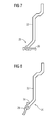
- FIG 7 illustrates a schematic top view of the hinge 20 for the oven door 10 in a closed state according to the preferred embodiment of the present invention.
- the plane of the door panel 32 extends in parallel to the front side of the cooking oven 12.
- a central portion of the upper hinge element 22 and the central hinge element 26 form an angle of 90 degrees in the closed state of the oven door 10.
- the lower hinge element 24 is arranged below the upper hinge element 22 and therefore not visible in FIG 7 .
- FIG 8 illustrates a schematic top view of the hinge 20 for the oven door 10 in an open state according to the preferred embodiment of the present invention.
- the shown open state of the hinge 20 corresponds with an aperture angle of 110 degrees between the plane of the door panel 32 of the oven door 10 and the front side of the cooking oven 12.
- the central portion of the upper hinge element 22 and the central hinge element 26 form an angle of about 110 degrees in the open state of the oven door 10.
- the lower hinge element 24 is arranged below the upper hinge element 22 and therefore not visible in FIG 8 .
- a mechanical stop 36 is formed between the upper hinge element 22 and the central hinge element 26 and between the lower hinge element 24 and the central hinge element 26, respectively, so that the opening angle of the oven door 10 is limited to a predetermined angle.
- the mechanical stop 36 effects the maximum aperture angle of 110 degrees between the plane of the door panel 32 of the oven door 10 and the front side of the cooking oven 12.
- FIG 9 illustrates an exploded perspective rear view of the oven door 10 for the cooking oven 12 according to the preferred embodiment of the present invention.
- FIG 9 shows the door panel 32 and the central hinge portion 26, before said central hinge portion 26 is glued to the door panel 10.
- the silicon glue 34 is applied on three places at the inner side of the door panel 32. Said three places are arranged one upon the other and provided for the central hinge portion 26. Thus, the central hinge portion 26 is directly attached at the door panel 32 of the oven door 10. There are no further fastening elements between the central hinge portion 26 and the door panel 32 of the oven door 10.
- FIG 10 illustrates an exploded perspective front view of the oven door 10 for the cooking oven 12 according to the preferred embodiment of the present invention.
- FIG 10 shows the door panel 32, the central hinge portion 26 and the silicon glue 34 between said door panel 32 and central hinge portion 26, before the silicon glue is applied to the inner side of the door panel 10.
- the central hinge portion 26 of the hinge 20 can be glued to the door panel 32 of the oven door 10 by an automatic system and/or an automatic procedure.
- the same automatic system and/or automatic procedure, respectively, can be used to glue other structural parts of the oven door 10 to the door panel 32.
- the vertical frame parts 28 and the horizontal frame part 30 are also glued to the inner side of the door panel 32 of the oven door 10.
- the properties of the door panel 32, the central hinge portion 26 and the other structural parts of the oven door 10 are independent of each other.
- the door panel 32, the central hinge portion 26, the vertical frame parts 28 and/or the horizontal frame part 30 are interchangeable.
- an arbitrary number of different oven doors 10 may be assembled by the same automatic system and/or procedure.
- the hinge 20 may be made of metal and/or a polymer material resistant to high temperatures.
- the upper hinge element 22, the lower hinge element 24 and/or the central hinge element 26 may be made of different materials.
- the material of the hinge 20 can be adapted to the material of the door panel 32, the vertical frame parts 28 and/or the horizontal frame part 30 in order to obtain a preferred design.
- the door panel may be made of glass.
Landscapes
- Engineering & Computer Science (AREA)
- Chemical & Material Sciences (AREA)
- Combustion & Propulsion (AREA)
- Mechanical Engineering (AREA)
- General Engineering & Computer Science (AREA)
- Electric Ovens (AREA)
Abstract
Description
- The present invention relates to an oven door for a cooking oven according to the preamble of claim 1. In particular, the present invention relates to a swing oven door for a cooking oven. Further, the present invention relates to a method for preparing an oven door for a cooking oven according to the preamble of claim 11. Moreover, the present invention relates to a cooking oven.
- An oven door, in particular a swing oven door is attached at a cooking oven by one or more hinges. In a closed state of the swing oven door the hinges are visible or not visible. Usually, the hinges are made of metal and fastened at the door structure by screws, rivets or similar fixing elements. The assembling of the hinges at the door structure takes a lot of time. Further, corrosion problems may occur at the metal hinges. Moreover, it is expensive to adapt the colour of the hinges to the design of the oven door and the cooking oven.
-
WO 2010/132057 A1 discloses an oven door pivotable around a horizontal axis. The oven door includes a glass panel, on which fittings are glued. Said fitting are provided for being connected to a hinge portion of a hinge for the oven door. However, the connection between the oven door and the oven is relative complex. - It is an object of the present invention to provide an oven door for a cooking oven and a method for preparing an oven door for a cooking oven, wherein said oven door is assembled by low complexity.
- The object of the present invention is achieved by the oven door for a cooking oven according to claim 1.
- According to the present invention the at least one first hinge portion is glued at the door panel. The at least one counter hinge portion is connectable to the cooking oven by another arbitrary method. Since the hinge portion is directly glued at the door panel, no additional parts are required. The hinge portion can be glued to the door panel by an automatic system and/or an automatic procedure. The properties of the door panel and the hinge portions are independent of each other. The door panel and the central hinge portion are interchangeable. Thus, an arbitrary number of different oven doors may be assembled by the same automatic system and/or procedure.
- In particular, the at least one second hinge portion may be detachably or permanently fixable or fixed at the cooking oven.
- For example, the at least one second hinge portion is fixable or fixed at a side wall frame of the cooking oven by screws and/or rivets.
- Preferably, the at least one first hinge portion is glued at the door panel by a silicon glue.
- According to an alternative embodiment of the present invention the at least one first hinge portion is glued at a door frame supporting one or more door panels.
- Further, at least one of the first hinge portion and the second hinge portion may be made of plastics. This prevents or restricts corrosion problems.
- Preferably, the hinge is arranged behind the oven door or the door panel of said oven door, when the oven door is in a closed state. This arrangement is advantageous for the design of the cooking oven.
- Additionally, the hinge may comprise a mechanical stop for limiting an aperture angle between the oven door and the cooking oven.
- In particular, a pivoting axis of the hinge extends along a vertical direction.
- Moreover, at least one of the first hinge portion and the second hinge portion (22, 24) may be made of metal.
- The object of the present invention is further achieved by the method for preparing an oven door for a cooking oven according to claim 11.
- According to the present invention the at least one first hinge portion is glued at the door panel.
- The hinge portion is directly glued at the door panel, so that no additional parts are required. The hinge portion can be glued to the door panel by an automatic system and/or an automatic procedure. Thus, an arbitrary number of different oven doors may be assembled by the same automatic system and/or procedure.
- Preferably, the gluing of the at least one first hinge portion at the door panel is performed by an automatic procedure. This reduces the production time.
- In a similar way, further structural elements of the oven door are glued at the door panel by the same automatic procedure.
- In particular, the method is provided for preparing the oven door mentioned above.
- At last, the present invention relates to a cooking oven including at least one oven door, in particular at least one swing oven door mentioned above.
- In particular the oven is a built-in type oven, i.e. an oven structured and dimensioned so as to be mounted into a cavity of a furniture article.
- The novel and inventive features believed to be the characteristic of the present invention are set forth in the appended claims.
- The invention will be described in further detail with reference to the drawings, in which
- FIG 1
- illustrates a front view of an oven door at a cooking oven according to a preferred embodiment of the present invention,
- FIG 2
- illustrates a perspective rear view of the oven door for the cooking oven according to the preferred embodiment of the present invention,
- FIG 3
- illustrates a perspective front view of the oven door for the cooking oven according to the preferred embodiment of the present invention,
- FIG 4
- illustrates a rear view of the oven door for the cooking oven according to the preferred embodiment of the present invention,
- FIG 5
- illustrates a perspective view of the cooking oven with the oven door in an open state according to the preferred embodiment of the present invention,
- FIG 6
- illustrates a detailed perspective view of a hinge at the oven door of the cooking oven according to the preferred embodiment of the present invention,
- FIG 7
- illustrates a schematic top view of the hinge for the oven door in a closed state according to the preferred embodiment of the present invention,
- FIG 8
- illustrates a schematic top view of the hinge for the oven door in an open state according to the preferred embodiment of the present invention,
- FIG 9
- illustrates an exploded perspective rear view of the oven door for the cooking oven according to the preferred embodiment of the present invention, and
- FIG 10
- illustrates an exploded perspective front view of the oven door for the cooking oven according to the preferred embodiment of the present invention.
-
FIG 1 illustrates a front view of anoven door 10 at acooking oven 12 according to a preferred embodiment of the present invention. Theoven door 10 is in a closed state and arranged at a front side of thecooking oven 12. Further, an upperfront panel 14 is also arranged at the front side of thecooking oven 12. The upperfront panel 14 is arranged above theoven door 10. - The
oven door 10 is a swing oven door pivotable around a vertical axis. In this example, said vertical axis is on the left hand side of the oven door. Theoven door 10 comprises a correspondingvertical hinge 20 at the left hand side. Thehinge 20 is arranged at the rear side of theoven door 10, such that, when the oven door is mounted on a built-in type oven, and the oven is, in turn, mounted into a cavity of a furniture article, saidhinge 20 is not visible in the closed state of saidoven door 10. - The
oven door 10 comprises awindow 16. Thewindow 16 is arranged in the central portion of theoven door 10. Further, theoven door 10 comprises two screw holes 18 provided for fixing a door handle. The screw holes 18 are arranged on the right hand side of theoven door 10. -
FIG 2 illustrates a perspective rear view of theoven door 10 for thecooking oven 12 according to the preferred embodiment of the present invention. Theoven door 10 includes adoor panel 32 and thehinge 20.FIG 2 clarifies the arrangement of thehinge 20 at thedoor panel 32 of theoven door 10. - The
hinge 20 includes anupper hinge element 22, alower hinge element 24 and acentral hinge element 26. Thecentral hinge element 26 is elongated along the vertical direction. Thecentral hinge element 26 is connected to thedoor panel 32 of theoven door 10 by an adhesive. In this example, thecentral hinge element 26 is fixed at thedoor panel 32 bysilicon glue 34. Theupper hinge element 22 and thelower hinge element 24 are pivotable at thecentral hinge element 26 in each case. Thus, theupper hinge element 22 and thelower hinge element 24 are pivotable at theoven door 10. - The
upper hinge element 22 and thelower hinge element 24 are connectable to a chassis of thecooking oven 12. In particular, theupper hinge element 22 and thelower hinge element 24 are provided for fastening theoven door 10 at a front frame of thecooking oven 12. For example, theupper hinge element 22 and thelower hinge element 24 are connectable to a chassis of thecooking oven 12 by screws. -
FIG 3 illustrates a perspective front view of theoven door 10 for thecooking oven 12 according to the preferred embodiment of the present invention.FIG 3 clarifies the arrangement of theupper hinge element 22, thelower hinge element 24 and thecentral hinge element 26 on the left hand side of theoven door 10. - The
central hinge element 26 extends over the nearly complete height of thedoor panel 32 of theoven door 10. Theupper hinge element 22 is pivotable at the upper end of thecentral hinge element 26. In a similar way, thelower hinge element 24 is pivotable at the lower end of thecentral hinge element 26. -
FIG 4 illustrates a rear view of theoven door 10 for thecooking oven 12 according to the preferred embodiment of the present invention. InFIG 4 furtherstructural elements oven door 10 are shown. - Two
vertical frame parts 28 and ahorizontal frame part 30 are arranged at the inner side of thedoor panel 32 of theoven door 10. Thevertical frame parts 28 are arranged at the left hand side and right hand side, respectively, beside thewindow 16 of theoven door 10. Thehorizontal frame part 30 is arranged above thewindow 16 of theoven door 10. Thevertical frame parts 28 and thehorizontal frame part 30 enclose thewindow 16 from three sides. Thevertical frame part 28 on the left hand side from the outside of theoven door 10 is arranged between thehinge 20 and thewindow 16. -
FIG 5 illustrates a perspective view of thecooking oven 12 with theoven door 10 in an open state according to the preferred embodiment of the present invention. Theupper hinge element 22 and thelower hinge element 24 of thehinge 20 are fixed at a left hand side of the front frame of thecooking oven 12. -
FIG 6 illustrates a detailed perspective view of thehinge 20 at theoven door 10 of thecooking oven 12 according to the preferred embodiment of the present invention.FIG 6 clarifies thatupper hinge element 22 and thelower hinge element 24 of thehinge 20 are fixed at an outer side of the front frame of thecooking oven 12. When the oven door is mounted on a built-in type oven, and the oven is, in turn, mounted into a cavity of a furniture article, thehinge 20 is only visible, when theoven door 10 is open. -
FIG 7 illustrates a schematic top view of thehinge 20 for theoven door 10 in a closed state according to the preferred embodiment of the present invention. In the closed state of theoven door 10 the plane of thedoor panel 32 extends in parallel to the front side of thecooking oven 12. A central portion of theupper hinge element 22 and thecentral hinge element 26 form an angle of 90 degrees in the closed state of theoven door 10. Thelower hinge element 24 is arranged below theupper hinge element 22 and therefore not visible inFIG 7 . -
FIG 8 illustrates a schematic top view of thehinge 20 for theoven door 10 in an open state according to the preferred embodiment of the present invention. The shown open state of thehinge 20 corresponds with an aperture angle of 110 degrees between the plane of thedoor panel 32 of theoven door 10 and the front side of thecooking oven 12. The central portion of theupper hinge element 22 and thecentral hinge element 26 form an angle of about 110 degrees in the open state of theoven door 10. Thelower hinge element 24 is arranged below theupper hinge element 22 and therefore not visible inFIG 8 . - Further, a
mechanical stop 36 is formed between theupper hinge element 22 and thecentral hinge element 26 and between thelower hinge element 24 and thecentral hinge element 26, respectively, so that the opening angle of theoven door 10 is limited to a predetermined angle. In this example, themechanical stop 36 effects the maximum aperture angle of 110 degrees between the plane of thedoor panel 32 of theoven door 10 and the front side of thecooking oven 12. -
FIG 9 illustrates an exploded perspective rear view of theoven door 10 for thecooking oven 12 according to the preferred embodiment of the present invention.FIG 9 shows thedoor panel 32 and thecentral hinge portion 26, before saidcentral hinge portion 26 is glued to thedoor panel 10. - The
silicon glue 34 is applied on three places at the inner side of thedoor panel 32. Said three places are arranged one upon the other and provided for thecentral hinge portion 26. Thus, thecentral hinge portion 26 is directly attached at thedoor panel 32 of theoven door 10. There are no further fastening elements between thecentral hinge portion 26 and thedoor panel 32 of theoven door 10. -
FIG 10 illustrates an exploded perspective front view of theoven door 10 for thecooking oven 12 according to the preferred embodiment of the present invention.FIG 10 shows thedoor panel 32, thecentral hinge portion 26 and thesilicon glue 34 between saiddoor panel 32 andcentral hinge portion 26, before the silicon glue is applied to the inner side of thedoor panel 10. - The
central hinge portion 26 of thehinge 20 can be glued to thedoor panel 32 of theoven door 10 by an automatic system and/or an automatic procedure. The same automatic system and/or automatic procedure, respectively, can be used to glue other structural parts of theoven door 10 to thedoor panel 32. In particular, thevertical frame parts 28 and thehorizontal frame part 30 are also glued to the inner side of thedoor panel 32 of theoven door 10. - The properties of the
door panel 32, thecentral hinge portion 26 and the other structural parts of theoven door 10 are independent of each other. Thedoor panel 32, thecentral hinge portion 26, thevertical frame parts 28 and/or thehorizontal frame part 30 are interchangeable. Thus, an arbitrary number ofdifferent oven doors 10 may be assembled by the same automatic system and/or procedure. - The
hinge 20 may be made of metal and/or a polymer material resistant to high temperatures. Theupper hinge element 22, thelower hinge element 24 and/or thecentral hinge element 26 may be made of different materials. The material of thehinge 20 can be adapted to the material of thedoor panel 32, thevertical frame parts 28 and/or thehorizontal frame part 30 in order to obtain a preferred design. The door panel may be made of glass. - Although an illustrative embodiment of the present invention has been described herein with reference to the accompanying drawings, it is to be understood that the present invention is not limited to that precise embodiment, and that various other changes and modifications may be affected therein by one skilled in the art without departing from the scope of the invention. All such changes and modifications are intended to be included within the scope of the invention as defined by the appended claims.
-
- 10
- oven door
- 12
- cooking oven
- 14
- upper front panel
- 16
- window
- 18
- screw hole
- 20
- hinge
- 22
- upper hinge element
- 24
- lower hinge element
- 26
- central hinge element
- 28
- vertical frame part
- 30
- horizontal frame part
- 32
- door panel
- 34
- silicon glue
- 36
- mechanical stop
Claims (15)
- An oven door (10), in particular a swing oven door (10) for a cooking oven (12), wherein- the oven door (10) comprises a door panel (32),- the oven door (10) comprises a hinge (20),- the hinge (20) includes at least one first hinge portion (26) fixed at the door panel (32) of the cooking oven (12),- the hinge (20) includes at least one second hinge portion (22, 24) fixable or fixed at the cooking oven (12), and- the at least one first hinge portion (26) and the at least one second hinge portion (22, 24) are pivoting to each other around a predetermined axis,characterized in, that
the at least one first hinge portion (26) is glued at the door panel (32). - The oven door according to claim 1,
characterized in, that
the at least one second hinge portion (22, 24) is detachably or permanently fixable or fixed at the cooking oven (12). - The oven door according to claim 1 or 2,
characterized in, that
the at least one second hinge portion (22, 24) is fixable or fixed at a side wall frame of the cooking oven by screws and/or rivets. - The oven door according to any one of the preceding claims,
characterized in, that
the at least one first hinge portion (26) is glued at the door panel (32) by a silicon glue. - The oven door according to any one of the preceding claims,
characterized in, that
the at least one first hinge portion (26) is glued at a door frame supporting one or more door panels (32). - The oven door according to any one of the preceding claims,
characterized in, that
at least one of the first hinge portion (26) and the second hinge portion (22, 24) is made of plastics. - The oven door according to any one of the preceding claims,
characterized in, that
the hinge (20) is arranged behind the oven door (10) or the door panel (32) of said oven door (10), when the oven door (10) is in a closed state. - The oven door according to any one of the preceding claims,
characterized in, that
the hinge (20) comprises a mechanical stop (36) for limiting an aperture angle between the oven door (10) and the cooking oven (12). - The oven door according to any one of the preceding claims,
characterized in, that
a pivoting axis of the hinge (20) extends along a vertical direction. - The oven door according to any one of the preceding claims,
characterized in, that
at least one of the first hinge portion (26) and the second hinge portion (22, 24) is made of metal. - A method for preparing an oven door (10), in particular a swing oven door (10) for a cooking oven (12), wherein the method comprises the steps of:- providing a door panel (32),- providing a hinge (20) including at least one first hinge portion (26) for the door panel (32) and at least one second hinge portion (22, 24) fixable at the cooking oven (12), wherein the first hinge portion (26) and the second hinge portion (22, 24) are pivoting to each other around a predetermined axis, and- fastening the at least one first hinge portion (26) at the door panel (32),characterized in, that
the at least one first hinge portion (26) is glued at the door panel (32). - The method according to claim 11,
characterized in, that
the gluing of the at least one first hinge portion (26) at the door panel (32) is performed by an automatic procedure. - The method according to claim 12,
characterized in, that
further structural elements (28, 30) of the oven door (10) are glued at the door panel (32) by the same automatic procedure. - The method according to any one of the claims 11 to 13, characterized in, that
the method is provided for an oven door (10) according to any one of the claims 1 to 10. - A cooking oven (12) including at least one oven door (10), in particular at least one swing oven door (10), characterized in, that
the cooking oven (12) includes at least one oven door (10) according to any one of the claims 1 to 10.
Priority Applications (1)
| Application Number | Priority Date | Filing Date | Title |
|---|---|---|---|
| EP12158271.2A EP2636956B1 (en) | 2012-03-06 | 2012-03-06 | An oven door for a cooking oven and a method for preparing an oven door for a cooking oven |
Applications Claiming Priority (1)
| Application Number | Priority Date | Filing Date | Title |
|---|---|---|---|
| EP12158271.2A EP2636956B1 (en) | 2012-03-06 | 2012-03-06 | An oven door for a cooking oven and a method for preparing an oven door for a cooking oven |
Publications (2)
| Publication Number | Publication Date |
|---|---|
| EP2636956A1 true EP2636956A1 (en) | 2013-09-11 |
| EP2636956B1 EP2636956B1 (en) | 2017-12-13 |
Family
ID=45808280
Family Applications (1)
| Application Number | Title | Priority Date | Filing Date |
|---|---|---|---|
| EP12158271.2A Active EP2636956B1 (en) | 2012-03-06 | 2012-03-06 | An oven door for a cooking oven and a method for preparing an oven door for a cooking oven |
Country Status (1)
| Country | Link |
|---|---|
| EP (1) | EP2636956B1 (en) |
Cited By (1)
| Publication number | Priority date | Publication date | Assignee | Title |
|---|---|---|---|---|
| CN107052766A (en) * | 2017-04-11 | 2017-08-18 | 广东沃尔姆斯电器有限公司 | Oven glass door panel assembly equipment |
Citations (7)
| Publication number | Priority date | Publication date | Assignee | Title |
|---|---|---|---|---|
| US4146769A (en) * | 1977-08-24 | 1979-03-27 | Litton Systems, Inc. | Microwave oven door |
| US4711982A (en) * | 1986-05-30 | 1987-12-08 | Litton Systems, Inc. | Plastic microwave oven door |
| GB2310876A (en) * | 1996-03-04 | 1997-09-10 | Creda Ltd | Fixing a bracket to a panel, particularly to the glass of an oven door |
| EP0823830A1 (en) * | 1996-08-06 | 1998-02-11 | Samsung Electronics Co., Ltd. | Microwave oven with improved door |
| GB2409896A (en) * | 2004-01-06 | 2005-07-13 | Tom Chandley Ltd | A powered oven door featuring non-parallel planar members |
| WO2010132057A1 (en) | 2009-05-14 | 2010-11-18 | Schott Gemtron Corporation | Full-view oven doors having locking mechanisms |
| DE102010003897A1 (en) * | 2010-04-13 | 2011-10-13 | BSH Bosch und Siemens Hausgeräte GmbH | Hinge for a household appliance door |
Family Cites Families (3)
| Publication number | Priority date | Publication date | Assignee | Title |
|---|---|---|---|---|
| US5901637A (en) * | 1998-04-06 | 1999-05-11 | Appliance Development Corporation | Combined baking oven and automatic bread baking apparatus |
| DE19960722C2 (en) * | 1999-12-16 | 2002-08-01 | Dorma Gmbh & Co Kg | Adjustable fitting |
| DE102007023321C5 (en) * | 2007-05-16 | 2014-10-23 | Dorma Gmbh + Co. Kg | Hardware for rotatably supporting a door |
-
2012
- 2012-03-06 EP EP12158271.2A patent/EP2636956B1/en active Active
Patent Citations (7)
| Publication number | Priority date | Publication date | Assignee | Title |
|---|---|---|---|---|
| US4146769A (en) * | 1977-08-24 | 1979-03-27 | Litton Systems, Inc. | Microwave oven door |
| US4711982A (en) * | 1986-05-30 | 1987-12-08 | Litton Systems, Inc. | Plastic microwave oven door |
| GB2310876A (en) * | 1996-03-04 | 1997-09-10 | Creda Ltd | Fixing a bracket to a panel, particularly to the glass of an oven door |
| EP0823830A1 (en) * | 1996-08-06 | 1998-02-11 | Samsung Electronics Co., Ltd. | Microwave oven with improved door |
| GB2409896A (en) * | 2004-01-06 | 2005-07-13 | Tom Chandley Ltd | A powered oven door featuring non-parallel planar members |
| WO2010132057A1 (en) | 2009-05-14 | 2010-11-18 | Schott Gemtron Corporation | Full-view oven doors having locking mechanisms |
| DE102010003897A1 (en) * | 2010-04-13 | 2011-10-13 | BSH Bosch und Siemens Hausgeräte GmbH | Hinge for a household appliance door |
Cited By (1)
| Publication number | Priority date | Publication date | Assignee | Title |
|---|---|---|---|---|
| CN107052766A (en) * | 2017-04-11 | 2017-08-18 | 广东沃尔姆斯电器有限公司 | Oven glass door panel assembly equipment |
Also Published As
| Publication number | Publication date |
|---|---|
| EP2636956B1 (en) | 2017-12-13 |
Similar Documents
| Publication | Publication Date | Title |
|---|---|---|
| EP2731404B1 (en) | An oven door for a microwave oven or a multifunctional oven with microwave heating function | |
| US20120031389A1 (en) | Oven door | |
| US20150233161A1 (en) | Hinge for furniture | |
| WO2007098955A3 (en) | Switchgear cabinet | |
| HK1203284A2 (en) | Forced entry resistance system for wooden doors | |
| EP2636956B1 (en) | An oven door for a cooking oven and a method for preparing an oven door for a cooking oven | |
| EP3064088B1 (en) | Hidden hanging bracket for the wall assembly of a structural component of a piece of furniture, with regulation from above | |
| US20190125078A1 (en) | Mounting device and domestic appliance | |
| EP2267262B1 (en) | Overhead door with two-way hinge for a wicket door | |
| US20080067303A1 (en) | Universal Bracket Used to Fix Doors to Cabinet Pull-Out Baskets | |
| EP2372059B1 (en) | A door hinge device for an oven cavity of a cooking oven | |
| EP3104084A1 (en) | Domestic oven | |
| EP2554735A1 (en) | A top-loading washing machine comprising a pivoting lid | |
| US10550616B2 (en) | Hinge for doors | |
| EP2580987B1 (en) | A drawer including a drawer panel and a drawer box | |
| WO2016012602A1 (en) | Modular profile system for suspending a door of a kitchen appliance | |
| US20090243452A1 (en) | Appliance | |
| EP2636957B1 (en) | A cooking oven including a swinging oven door with a closure system of said door | |
| GB2410766A (en) | Hinge mounting unit for door | |
| EP2390584A1 (en) | Cabinet for a domestic appliance | |
| WO2019042659A1 (en) | A cooking device comprising a spacer | |
| CN109745573B (en) | Disinfection cabinet bracket and disinfection cabinet | |
| EP2301386A1 (en) | Door, suitable for furniture, with decorative elements | |
| EP1818495A1 (en) | Method of fabricating a door or window frame for a boat and door or window for a boat | |
| EP2096049A1 (en) | Multiple container assembly for domestic waste |
Legal Events
| Date | Code | Title | Description |
|---|---|---|---|
| PUAI | Public reference made under article 153(3) epc to a published international application that has entered the european phase |
Free format text: ORIGINAL CODE: 0009012 |
|
| AK | Designated contracting states |
Kind code of ref document: A1 Designated state(s): AL AT BE BG CH CY CZ DE DK EE ES FI FR GB GR HR HU IE IS IT LI LT LU LV MC MK MT NL NO PL PT RO RS SE SI SK SM TR |
|
| AX | Request for extension of the european patent |
Extension state: BA ME |
|
| 17P | Request for examination filed |
Effective date: 20140311 |
|
| RBV | Designated contracting states (corrected) |
Designated state(s): AL AT BE BG CH CY CZ DE DK EE ES FI FR GB GR HR HU IE IS IT LI LT LU LV MC MK MT NL NO PL PT RO RS SE SI SK SM TR |
|
| 17Q | First examination report despatched |
Effective date: 20160415 |
|
| GRAP | Despatch of communication of intention to grant a patent |
Free format text: ORIGINAL CODE: EPIDOSNIGR1 |
|
| INTG | Intention to grant announced |
Effective date: 20170622 |
|
| GRAS | Grant fee paid |
Free format text: ORIGINAL CODE: EPIDOSNIGR3 |
|
| GRAA | (expected) grant |
Free format text: ORIGINAL CODE: 0009210 |
|
| AK | Designated contracting states |
Kind code of ref document: B1 Designated state(s): AL AT BE BG CH CY CZ DE DK EE ES FI FR GB GR HR HU IE IS IT LI LT LU LV MC MK MT NL NO PL PT RO RS SE SI SK SM TR |
|
| REG | Reference to a national code |
Ref country code: GB Ref legal event code: FG4D |
|
| REG | Reference to a national code |
Ref country code: AT Ref legal event code: REF Ref document number: 954774 Country of ref document: AT Kind code of ref document: T Effective date: 20171215 Ref country code: CH Ref legal event code: EP |
|
| REG | Reference to a national code |
Ref country code: IE Ref legal event code: FG4D |
|
| REG | Reference to a national code |
Ref country code: DE Ref legal event code: R096 Ref document number: 602012040764 Country of ref document: DE |
|
| REG | Reference to a national code |
Ref country code: FR Ref legal event code: PLFP Year of fee payment: 7 |
|
| REG | Reference to a national code |
Ref country code: NL Ref legal event code: MP Effective date: 20171213 |
|
| REG | Reference to a national code |
Ref country code: LT Ref legal event code: MG4D |
|
| PG25 | Lapsed in a contracting state [announced via postgrant information from national office to epo] |
Ref country code: FI Free format text: LAPSE BECAUSE OF FAILURE TO SUBMIT A TRANSLATION OF THE DESCRIPTION OR TO PAY THE FEE WITHIN THE PRESCRIBED TIME-LIMIT Effective date: 20171213 Ref country code: LT Free format text: LAPSE BECAUSE OF FAILURE TO SUBMIT A TRANSLATION OF THE DESCRIPTION OR TO PAY THE FEE WITHIN THE PRESCRIBED TIME-LIMIT Effective date: 20171213 Ref country code: NO Free format text: LAPSE BECAUSE OF FAILURE TO SUBMIT A TRANSLATION OF THE DESCRIPTION OR TO PAY THE FEE WITHIN THE PRESCRIBED TIME-LIMIT Effective date: 20180313 Ref country code: SE Free format text: LAPSE BECAUSE OF FAILURE TO SUBMIT A TRANSLATION OF THE DESCRIPTION OR TO PAY THE FEE WITHIN THE PRESCRIBED TIME-LIMIT Effective date: 20171213 |
|
| REG | Reference to a national code |
Ref country code: AT Ref legal event code: MK05 Ref document number: 954774 Country of ref document: AT Kind code of ref document: T Effective date: 20171213 |
|
| PG25 | Lapsed in a contracting state [announced via postgrant information from national office to epo] |
Ref country code: HR Free format text: LAPSE BECAUSE OF FAILURE TO SUBMIT A TRANSLATION OF THE DESCRIPTION OR TO PAY THE FEE WITHIN THE PRESCRIBED TIME-LIMIT Effective date: 20171213 Ref country code: BG Free format text: LAPSE BECAUSE OF FAILURE TO SUBMIT A TRANSLATION OF THE DESCRIPTION OR TO PAY THE FEE WITHIN THE PRESCRIBED TIME-LIMIT Effective date: 20180313 Ref country code: GR Free format text: LAPSE BECAUSE OF FAILURE TO SUBMIT A TRANSLATION OF THE DESCRIPTION OR TO PAY THE FEE WITHIN THE PRESCRIBED TIME-LIMIT Effective date: 20180314 Ref country code: RS Free format text: LAPSE BECAUSE OF FAILURE TO SUBMIT A TRANSLATION OF THE DESCRIPTION OR TO PAY THE FEE WITHIN THE PRESCRIBED TIME-LIMIT Effective date: 20171213 Ref country code: LV Free format text: LAPSE BECAUSE OF FAILURE TO SUBMIT A TRANSLATION OF THE DESCRIPTION OR TO PAY THE FEE WITHIN THE PRESCRIBED TIME-LIMIT Effective date: 20171213 |
|
| PG25 | Lapsed in a contracting state [announced via postgrant information from national office to epo] |
Ref country code: NL Free format text: LAPSE BECAUSE OF FAILURE TO SUBMIT A TRANSLATION OF THE DESCRIPTION OR TO PAY THE FEE WITHIN THE PRESCRIBED TIME-LIMIT Effective date: 20171213 |
|
| PG25 | Lapsed in a contracting state [announced via postgrant information from national office to epo] |
Ref country code: ES Free format text: LAPSE BECAUSE OF FAILURE TO SUBMIT A TRANSLATION OF THE DESCRIPTION OR TO PAY THE FEE WITHIN THE PRESCRIBED TIME-LIMIT Effective date: 20171213 Ref country code: CZ Free format text: LAPSE BECAUSE OF FAILURE TO SUBMIT A TRANSLATION OF THE DESCRIPTION OR TO PAY THE FEE WITHIN THE PRESCRIBED TIME-LIMIT Effective date: 20171213 Ref country code: CY Free format text: LAPSE BECAUSE OF FAILURE TO SUBMIT A TRANSLATION OF THE DESCRIPTION OR TO PAY THE FEE WITHIN THE PRESCRIBED TIME-LIMIT Effective date: 20171213 Ref country code: EE Free format text: LAPSE BECAUSE OF FAILURE TO SUBMIT A TRANSLATION OF THE DESCRIPTION OR TO PAY THE FEE WITHIN THE PRESCRIBED TIME-LIMIT Effective date: 20171213 Ref country code: SK Free format text: LAPSE BECAUSE OF FAILURE TO SUBMIT A TRANSLATION OF THE DESCRIPTION OR TO PAY THE FEE WITHIN THE PRESCRIBED TIME-LIMIT Effective date: 20171213 |
|
| PG25 | Lapsed in a contracting state [announced via postgrant information from national office to epo] |
Ref country code: RO Free format text: LAPSE BECAUSE OF FAILURE TO SUBMIT A TRANSLATION OF THE DESCRIPTION OR TO PAY THE FEE WITHIN THE PRESCRIBED TIME-LIMIT Effective date: 20171213 Ref country code: IS Free format text: LAPSE BECAUSE OF FAILURE TO SUBMIT A TRANSLATION OF THE DESCRIPTION OR TO PAY THE FEE WITHIN THE PRESCRIBED TIME-LIMIT Effective date: 20180413 Ref country code: AT Free format text: LAPSE BECAUSE OF FAILURE TO SUBMIT A TRANSLATION OF THE DESCRIPTION OR TO PAY THE FEE WITHIN THE PRESCRIBED TIME-LIMIT Effective date: 20171213 Ref country code: SM Free format text: LAPSE BECAUSE OF FAILURE TO SUBMIT A TRANSLATION OF THE DESCRIPTION OR TO PAY THE FEE WITHIN THE PRESCRIBED TIME-LIMIT Effective date: 20171213 Ref country code: PL Free format text: LAPSE BECAUSE OF FAILURE TO SUBMIT A TRANSLATION OF THE DESCRIPTION OR TO PAY THE FEE WITHIN THE PRESCRIBED TIME-LIMIT Effective date: 20171213 |
|
| REG | Reference to a national code |
Ref country code: DE Ref legal event code: R097 Ref document number: 602012040764 Country of ref document: DE |
|
| PLBE | No opposition filed within time limit |
Free format text: ORIGINAL CODE: 0009261 |
|
| STAA | Information on the status of an ep patent application or granted ep patent |
Free format text: STATUS: NO OPPOSITION FILED WITHIN TIME LIMIT |
|
| REG | Reference to a national code |
Ref country code: CH Ref legal event code: PL |
|
| 26N | No opposition filed |
Effective date: 20180914 |
|
| PG25 | Lapsed in a contracting state [announced via postgrant information from national office to epo] |
Ref country code: DK Free format text: LAPSE BECAUSE OF FAILURE TO SUBMIT A TRANSLATION OF THE DESCRIPTION OR TO PAY THE FEE WITHIN THE PRESCRIBED TIME-LIMIT Effective date: 20171213 Ref country code: MC Free format text: LAPSE BECAUSE OF FAILURE TO SUBMIT A TRANSLATION OF THE DESCRIPTION OR TO PAY THE FEE WITHIN THE PRESCRIBED TIME-LIMIT Effective date: 20171213 |
|
| REG | Reference to a national code |
Ref country code: BE Ref legal event code: MM Effective date: 20180331 |
|
| REG | Reference to a national code |
Ref country code: IE Ref legal event code: MM4A |
|
| PG25 | Lapsed in a contracting state [announced via postgrant information from national office to epo] |
Ref country code: LU Free format text: LAPSE BECAUSE OF NON-PAYMENT OF DUE FEES Effective date: 20180306 |
|
| PG25 | Lapsed in a contracting state [announced via postgrant information from national office to epo] |
Ref country code: IE Free format text: LAPSE BECAUSE OF NON-PAYMENT OF DUE FEES Effective date: 20180306 |
|
| PG25 | Lapsed in a contracting state [announced via postgrant information from national office to epo] |
Ref country code: BE Free format text: LAPSE BECAUSE OF NON-PAYMENT OF DUE FEES Effective date: 20180331 Ref country code: SI Free format text: LAPSE BECAUSE OF FAILURE TO SUBMIT A TRANSLATION OF THE DESCRIPTION OR TO PAY THE FEE WITHIN THE PRESCRIBED TIME-LIMIT Effective date: 20171213 Ref country code: CH Free format text: LAPSE BECAUSE OF NON-PAYMENT OF DUE FEES Effective date: 20180331 Ref country code: LI Free format text: LAPSE BECAUSE OF NON-PAYMENT OF DUE FEES Effective date: 20180331 |
|
| PG25 | Lapsed in a contracting state [announced via postgrant information from national office to epo] |
Ref country code: MT Free format text: LAPSE BECAUSE OF NON-PAYMENT OF DUE FEES Effective date: 20180306 |
|
| PG25 | Lapsed in a contracting state [announced via postgrant information from national office to epo] |
Ref country code: TR Free format text: LAPSE BECAUSE OF FAILURE TO SUBMIT A TRANSLATION OF THE DESCRIPTION OR TO PAY THE FEE WITHIN THE PRESCRIBED TIME-LIMIT Effective date: 20171213 |
|
| PG25 | Lapsed in a contracting state [announced via postgrant information from national office to epo] |
Ref country code: PT Free format text: LAPSE BECAUSE OF FAILURE TO SUBMIT A TRANSLATION OF THE DESCRIPTION OR TO PAY THE FEE WITHIN THE PRESCRIBED TIME-LIMIT Effective date: 20171213 Ref country code: HU Free format text: LAPSE BECAUSE OF FAILURE TO SUBMIT A TRANSLATION OF THE DESCRIPTION OR TO PAY THE FEE WITHIN THE PRESCRIBED TIME-LIMIT; INVALID AB INITIO Effective date: 20120306 |
|
| PG25 | Lapsed in a contracting state [announced via postgrant information from national office to epo] |
Ref country code: MK Free format text: LAPSE BECAUSE OF NON-PAYMENT OF DUE FEES Effective date: 20171213 |
|
| PG25 | Lapsed in a contracting state [announced via postgrant information from national office to epo] |
Ref country code: AL Free format text: LAPSE BECAUSE OF FAILURE TO SUBMIT A TRANSLATION OF THE DESCRIPTION OR TO PAY THE FEE WITHIN THE PRESCRIBED TIME-LIMIT Effective date: 20171213 |
|
| P01 | Opt-out of the competence of the unified patent court (upc) registered |
Effective date: 20230625 |
|
| PGFP | Annual fee paid to national office [announced via postgrant information from national office to epo] |
Ref country code: DE Payment date: 20250327 Year of fee payment: 14 |
|
| PGFP | Annual fee paid to national office [announced via postgrant information from national office to epo] |
Ref country code: FR Payment date: 20250324 Year of fee payment: 14 |
|
| PGFP | Annual fee paid to national office [announced via postgrant information from national office to epo] |
Ref country code: IT Payment date: 20250321 Year of fee payment: 14 Ref country code: GB Payment date: 20250325 Year of fee payment: 14 |