EP2636802A1 - Working machine - Google Patents
Working machine Download PDFInfo
- Publication number
- EP2636802A1 EP2636802A1 EP11837943.7A EP11837943A EP2636802A1 EP 2636802 A1 EP2636802 A1 EP 2636802A1 EP 11837943 A EP11837943 A EP 11837943A EP 2636802 A1 EP2636802 A1 EP 2636802A1
- Authority
- EP
- European Patent Office
- Prior art keywords
- operator
- cab
- rear window
- engine room
- face shape
- Prior art date
- Legal status (The legal status is an assumption and is not a legal conclusion. Google has not performed a legal analysis and makes no representation as to the accuracy of the status listed.)
- Withdrawn
Links
- 230000000007 visual effect Effects 0.000 abstract description 20
- 206010040007 Sense of oppression Diseases 0.000 abstract description 9
- 230000000694 effects Effects 0.000 description 6
- 239000003921 oil Substances 0.000 description 5
- 230000004048 modification Effects 0.000 description 4
- 238000012986 modification Methods 0.000 description 4
- 230000015572 biosynthetic process Effects 0.000 description 3
- 239000002689 soil Substances 0.000 description 3
- 239000002828 fuel tank Substances 0.000 description 2
- 239000011521 glass Substances 0.000 description 2
- 239000010720 hydraulic oil Substances 0.000 description 2
- 238000007689 inspection Methods 0.000 description 2
- 238000012423 maintenance Methods 0.000 description 2
- 238000009412 basement excavation Methods 0.000 description 1
- 238000010276 construction Methods 0.000 description 1
- 238000001816 cooling Methods 0.000 description 1
- 238000009423 ventilation Methods 0.000 description 1
Images




Classifications
-
- E—FIXED CONSTRUCTIONS
- E02—HYDRAULIC ENGINEERING; FOUNDATIONS; SOIL SHIFTING
- E02F—DREDGING; SOIL-SHIFTING
- E02F9/00—Component parts of dredgers or soil-shifting machines, not restricted to one of the kinds covered by groups E02F3/00 - E02F7/00
- E02F9/08—Superstructures; Supports for superstructures
- E02F9/0858—Arrangement of component parts installed on superstructures not otherwise provided for, e.g. electric components, fenders, air-conditioning units
- E02F9/0891—Lids or bonnets or doors or details thereof
-
- E—FIXED CONSTRUCTIONS
- E02—HYDRAULIC ENGINEERING; FOUNDATIONS; SOIL SHIFTING
- E02F—DREDGING; SOIL-SHIFTING
- E02F9/00—Component parts of dredgers or soil-shifting machines, not restricted to one of the kinds covered by groups E02F3/00 - E02F7/00
- E02F9/08—Superstructures; Supports for superstructures
-
- B—PERFORMING OPERATIONS; TRANSPORTING
- B62—LAND VEHICLES FOR TRAVELLING OTHERWISE THAN ON RAILS
- B62D—MOTOR VEHICLES; TRAILERS
- B62D25/00—Superstructure or monocoque structure sub-units; Parts or details thereof not otherwise provided for
- B62D25/08—Front or rear portions
- B62D25/10—Bonnets or lids, e.g. for trucks, tractors, busses, work vehicles
-
- B—PERFORMING OPERATIONS; TRANSPORTING
- B62—LAND VEHICLES FOR TRAVELLING OTHERWISE THAN ON RAILS
- B62D—MOTOR VEHICLES; TRAILERS
- B62D33/00—Superstructures for load-carrying vehicles
- B62D33/06—Drivers' cabs
- B62D33/0617—Drivers' cabs for tractors or off-the-road vehicles
-
- E—FIXED CONSTRUCTIONS
- E02—HYDRAULIC ENGINEERING; FOUNDATIONS; SOIL SHIFTING
- E02F—DREDGING; SOIL-SHIFTING
- E02F3/00—Dredgers; Soil-shifting machines
- E02F3/04—Dredgers; Soil-shifting machines mechanically-driven
- E02F3/28—Dredgers; Soil-shifting machines mechanically-driven with digging tools mounted on a dipper- or bucket-arm, i.e. there is either one arm or a pair of arms, e.g. dippers, buckets
- E02F3/30—Dredgers; Soil-shifting machines mechanically-driven with digging tools mounted on a dipper- or bucket-arm, i.e. there is either one arm or a pair of arms, e.g. dippers, buckets with a dipper-arm pivoted on a cantilever beam, i.e. boom
-
- E—FIXED CONSTRUCTIONS
- E02—HYDRAULIC ENGINEERING; FOUNDATIONS; SOIL SHIFTING
- E02F—DREDGING; SOIL-SHIFTING
- E02F9/00—Component parts of dredgers or soil-shifting machines, not restricted to one of the kinds covered by groups E02F3/00 - E02F7/00
-
- E—FIXED CONSTRUCTIONS
- E02—HYDRAULIC ENGINEERING; FOUNDATIONS; SOIL SHIFTING
- E02F—DREDGING; SOIL-SHIFTING
- E02F9/00—Component parts of dredgers or soil-shifting machines, not restricted to one of the kinds covered by groups E02F3/00 - E02F7/00
- E02F9/08—Superstructures; Supports for superstructures
- E02F9/0833—Improving access, e.g. for maintenance, steps for improving driver's access, handrails
-
- E—FIXED CONSTRUCTIONS
- E02—HYDRAULIC ENGINEERING; FOUNDATIONS; SOIL SHIFTING
- E02F—DREDGING; SOIL-SHIFTING
- E02F9/00—Component parts of dredgers or soil-shifting machines, not restricted to one of the kinds covered by groups E02F3/00 - E02F7/00
- E02F9/08—Superstructures; Supports for superstructures
- E02F9/0858—Arrangement of component parts installed on superstructures not otherwise provided for, e.g. electric components, fenders, air-conditioning units
- E02F9/0866—Engine compartment, e.g. heat exchangers, exhaust filters, cooling devices, silencers, mufflers, position of hydraulic pumps in the engine compartment
-
- E—FIXED CONSTRUCTIONS
- E02—HYDRAULIC ENGINEERING; FOUNDATIONS; SOIL SHIFTING
- E02F—DREDGING; SOIL-SHIFTING
- E02F9/00—Component parts of dredgers or soil-shifting machines, not restricted to one of the kinds covered by groups E02F3/00 - E02F7/00
- E02F9/16—Cabins, platforms, or the like, for drivers
-
- E—FIXED CONSTRUCTIONS
- E02—HYDRAULIC ENGINEERING; FOUNDATIONS; SOIL SHIFTING
- E02F—DREDGING; SOIL-SHIFTING
- E02F9/00—Component parts of dredgers or soil-shifting machines, not restricted to one of the kinds covered by groups E02F3/00 - E02F7/00
- E02F9/16—Cabins, platforms, or the like, for drivers
- E02F9/163—Structures to protect drivers, e.g. cabins, doors for cabins; Falling object protection structure [FOPS]; Roll over protection structure [ROPS]
Definitions
- the present invention relates to a working machine such as a hydraulic excavator, in which an operator's cab having a rear window and an engine room adjacent to the operator's cab are disposed on a revolving upperstructure.
- a working machine provided with a revolving upperstructure such as a hydraulic excavator, is restricted by the width of the revolving upperstructure and the size of rearward protrusion of a counter weight disposed at the rear of the revolving upperstructure in order to prevent the slewing radius from coming out of the vehicle width of a traveling base if possible.
- the height of the engine room needs to be set large.
- the height of the engine room tends to increase as the number of devices installed in the engine room increases or the size of each device increases.
- a slewing type working machine such as a hydraulic excavator has been disclosed as this type working machine in Patent Literature 1.
- the working machine has: an operator's cab, i.e. a cab provided in a front position of a revolving upperstructure, and an engine room provided in a rear position of the cab so as to be adjacent to the cab.
- a cooling device made of a heat exchanger, an engine, etc. are received in the engine room.
- the height of the engine room is set to be relatively large.
- a cover member forming a ceiling part of the engine room, i.e. a decorative cover is provided so as to extend substantially horizontally as a whole. Accordingly, an operator's cab side end portion of the decorative cover which forms the ceiling part of the engine room faces a relatively high position portion of the rear of the operator's cab.
- a rear window made of a glass window is usually disposed in the rear of the cab, i.e. the operator's cab, and an operator sitting on an operator's seat in the operator's cab can look at rearward of the vehicle body through the rear window.
- Patent Literature 1 Japanese Patent No. 3927429
- the decorative cover which forms the ceiling part of the engine room and which is provided so as to extend substantially horizontally as a whole is close to the rear window of the operator's cab. Accordingly, the operator sitting on the operator's seat in the operator's cab is apt to be oppressed psychologically by the engine room. Accordingly, the operator may feel it difficult to obtain comfortable handling property when the operator operates various hydraulic actuators. Moreover, the position of the decorative cover on the operator's cab side is relatively high. For this reason, when the operator sitting on the operator's seat is looking at rearward through the rear window, the visual field of the operator is blocked by the decorative cover so that the operator cannot see well and the rearward visual field of the operator is apt to be restricted. Accordingly, there is a fear that the performance of work which is carried out by the operator while the operator is looking at rearward may be lowered due to the restriction on the rearward visual field in the background art.
- An object of the invention is to provide a working machine which enables reduction of such a feeling of oppression that an operator sitting on an operator's seat is oppressed by an engine room and relaxation of restriction on a rearward visual field of the operator sitting on the operator's seat.
- a working machine including: a revolving upperstructure; a working device which is attached to the revolving upperstructure; an operator's cab which has a rear window and which is disposed in a front position of the revolving upperstructure; and an engine room which is disposed in a rear position adjacent to the operator's cab and which has a ceiling part made of a cover member; characterized in that: a part of the cover member located near the operator's cab is made of a face shape part having a shape whose height gradually increases toward the rear of a vehicle body with the vicinity of a lower end portion of the rear window as a start point during a predetermined distance immediately after the operator's cab.
- the shape of the part located near the operator's cab, of the cover member which forms the ceiling part of the engine room is made of the face shape part whose height gradually increases toward the rear of the vehicle body with the vicinity of the lower end portion of the rear window of the operator's cab as the start point during the predetermined distance immediately after the operator's cab so that the height of the ceiling part of the engine room is lowered during the predetermined distance immediately after the operator's cab. Accordingly, a space portion corresponding to the aforementioned predetermined distance can be formed between the rear window of the operator's cab and the ceiling part of the engine room.
- the space portion can reduce such a feeling of oppression that an operator sitting on an operator's seat in the operator's cab is oppressed by the engine room.
- the visual field lower limit of the rearward visual field of the operator sitting on the operator's seat can be lowered because of the formation of the aforementioned space portion when the position of the cover member which forms the ceiling part of the engine room is higher than an eye position of the operator sitting on the operator's seat. Accordingly, restriction on the rearward visual field of the operator sitting on the operator's seat can be relaxed.
- the visual field lower limit of the rearward visual field can be lowered. Accordingly, when a rearview mirror is disposed, the length of a stay supporting the rearview mirror can be set short.
- the invention having the aforementioned configuration is characterized in that the height of the start point of the face shape part is set to be equal to or lower than the height of the lower end portion of the rear window.
- the space portion formed between the rear window of the operator's cab and the ceiling part of the engine room can be kept so large as to contribute to reduction of such a feeling of oppression that the operator sitting on the operator's seat is oppressed by the engine room.
- the operator sitting on the operator's seat may break the rear window of the operator's cab to escape out of the operator's cab when there is an accident that the operator's cab is covered with soil etc. in work etc. performed by the construction machine.
- a large escape region corresponding to the whole of the rear window can be ensured for such operator's escape.
- the invention having the aforementioned configuration is characterized in that the face shape part of the cover member is disposed to be out of a rotational locus which is virtually drawn by the lower end portion of the rear window when the rear window is rotated on an upper end portion of the rear window toward the engine room.
- the space portion formed between the rear window of the operator's cab and the ceiling part of the engine room can be enlarged so as to contribute to reduction of such a feeling of oppression that the operator sitting on the operator's seat is oppressed by the engine room.
- a large escape region corresponding to the whole of the rear window can be ensured when the operator breaks the rear window of the operator's seat to escape out of the operator's cab.
- the invention having the aforementioned configuration is characterized in that: the cover member of the engine room includes the face shape part, and an engine cover which is provided so horizontally as to be consecutive to the face shape part and which can be opened/closed; and a handle which is attached to the engine cover and which is used when the engine cover is opened/closed is provided and disposed in the vicinity of an end portion of the engine cover located near the face shape part.
- a hand when the engine cover is opened for maintenance and inspection of devices received in the engine room, a hand can be put into the handle and hold the handle in the space portion formed between the rear window of the operator's cab and the ceiling part of the engine room so that an operation of opening/closing the engine cover can be performed easily.
- the invention having the aforementioned configuration is characterized in that a heat exchanger is disposed in a place in the engine room just under the face shape part of the cover member.
- the portion in the engine room just under the face shape part of the cover member can be used as a space where the heat exchanger having a relatively suppressed height is disposed.
- the part of the cover member which forms the ceiling part of the engine room located in the vicinity of the operator's cab is made of a face shape part having a shape whose height gradually increases toward the rear of the vehicle body with the vicinity of the lower end portion of the rear window of the operator's cab as the start point during a predetermined distance immediately after the operator's cab so that a space portion corresponding to the aforementioned predetermined distance can be formed between the rear window of the operator's cab and the ceiling part of the engine room.
- the space portion can reduce such a feeling of oppression that an operator sitting on the operator's seat is oppressed by the engine room, so that comfortable handling property can be ensured compared with the background art.
- a visual field lower limit of the rearward visual field of the operator sitting on the operator's seat can be lowered due to the formation of the aforementioned space portion. In this manner, restriction on the rearward visual field of the operator sitting on the operator's seat can be relaxed so that the performance of work performed by the operator while the operator is looking at rearward of the vehicle body can be improved compared with the background art.
- Fig. 1 is a side view showing a hydraulic excavator formed as a first embodiment of a working machine according to the invention.
- Fig. 2 is a perspective view showing a revolving upperstructure provided in the hydraulic excavator shown in Fig. 1 .
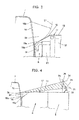
- Fig. 3 is an enlarged side sectional view of main part of the revolving upperstructure shown in Fig. 2 .
- the working machine according to the first embodiment of the invention is made of a hydraulic excavator.
- the hydraulic excavator has: a traveling base 1; a revolving upperstructure 2 which is disposed on the traveling base 1; and a working device 3 which is attached to the revolving upperstructure 2 so as to be rotatable vertically.
- the working device 3 has: a boom 4 which is attached to the revolving upperstructure 2 so as to be rotatable vertically; a boom cylinder 4a which actuates the boom 4; an arm 5 which is attached to a front end of the boom 4 so as to be rotatable vertically; an arm cylinder 5a which actuates the arm 5; a bucket 6 which is attached to a front end of the arm 5 so as to be rotatable vertically; and a bucket cylinder 6a which actuates the bucket 6.
- the hydraulic excavator can perform various kinds of work such as soil excavation work by traveling the traveling base 1 or slewing the revolving upperstructure 2 and rotating the working device 3 vertically.
- an operator's cab 7 is disposed in a front position of a slewing frame 2a of the revolving upperstructure 2 while a counter weight 8 is disposed in a rear position thereof.
- An engine room 9 in which heat exchangers, an engine etc. are received is disposed in a rear position adjacent to the operator's cab 7 with a predetermined gap, that is, between the operator's cab 7 and the counter weight 8.
- a rear window 16 made of a glass window is disposed in a rear part of the operator's cab 7.
- the rear window 16 is made of a fixed window which cannot be opened/closed.
- a ceiling part of the engine room 9 is made of a cover member 17.
- a side door 20 which is opened/closed for work of maintaining and inspecting devices in the engine room 9 is provided in a side part of the engine room 9.
- a large number of vents which lead outside air into the engine room 9 are formed in the side door 20.
- an upper cover 10 is disposed on a right side of the cover member 17 of the engine room 9 and in a front position of the counter weight 8.
- a hydraulic pump etc. driven by the engine is put below the upper cover 8.
- a hydraulic oil tank 11 and a fuel tank 12 are disposed in a forward right position of the upper cover 10.
- a right front cover 13 is disposed in a front position of the hydraulic oil tank 11 and the fuel tank 12.
- a control valve is disposed below the right front cover 13.
- a handrail 14 for making it easy to ride on an upper part of the revolving upperstructure 2 is provided on the revolving upperstructure 2.
- a right back mirror 15 is attached to an operator's cab 7 side part of the handrail 14.
- a part of the cover member 17 located near the operator's cab 7 is made of a face shape part having a shape whose height gradually increases toward the rear of a vehicle body with the vicinity of a lower end part 16a of the rear window 16 as a start point 18a during a predetermined distance immediately after the operator's cab 7.
- the face shape part is, for example, made of an inclined surface part 18.
- the width of the inclined surface part 18 is set, for example, to be equal to the width of the rear part of the operator's cab 7 where the rear window 16 is provided.
- the aforementioned predetermined distance immediately after the operator's cab 7 is set in accordance with the layout form of an oil cooler 23, a pipe arrangement 24, etc. received in the engine room 9.
- the pipe arrangement 24 connects the oil cooler 23 and the aforementioned control valve to each other.
- the height of the start point 18a of the aforementioned inclined surface part 18 is set as a height equal to or lower than the lower end part 16a of the rear window 16 of the operator's cab 7.
- the cover member 17 of the aforementioned engine room 9 includes the inclined surface part 18, and an engine cover 19 which is provided so horizontally as to be consecutive to the inclined surface part 18 and which can be opened/closed vertically.
- a handle 22 used when the engine cover 19 is opened/closed is attached to the engine cover 19. As shown in Fig. 2 , the handle 22 is disposed in the vicinity of an end part 19a of the engine cover 19 located near the inclined surface part 18.
- the inclined surface part 18 of the cover member 17 which forms the ceiling part of the engine room 9 is disposed so as to be located out of a rotational locus 21 which is virtually drawn by the lower end part 16a when the rear window 16 is rotated on an upper end part 16b of the rear window 16 toward the engine room 9.
- the inclined surface part 18 is set to have such an inclination angle that the inclined surface part 18 is substantially tangent to the rotational locus 21.
- Fig. 4 is a view for explaining functions and effects of the hydraulic excavator according to the first embodiment.
- the part located near the operator's cab 7, of the cover member 17 which forms the ceiling part of the engine room 9 is made of the inclined surface part 18 whose height gradually increases toward the rear of the vehicle body with the vicinity of the lower end part 16a of the rear window 16 of the operator's cab 7 as the start point 18a during the predetermined distance immediately after the operator's cab 7.
- the ceiling part of the engine room 9 is lowered during the predetermined distance immediately after the operator's cab 7, so that a space portion 50 corresponding to the aforementioned predetermined distance can be formed between the rear window 16 of the operator's cab 7 and the ceiling part of the engine room 9 as shown in Fig. 4 .
- the space portion 50 can reduce such a feeling of oppression that the operator sitting on the operator's seat of the operator's cab 7 is oppressed by the engine room 9. Accordingly, comfortable handling property can be ensured.
- a visual field lower limit 31 of the rearward visual field of the operator sitting on the operator's seat through the rear window 16 can be made lower than a visual field lower limit 34 in the case of the background-art hydraulic excavator, due to the formation of the aforementioned space portion 50. Accordingly, restriction on the rearward visual field of the operator sitting on the operator's seat can be relaxed so that the performance of work performed by the operator while the operator is looking at rearward of the vehicle body can be improved.
- the visual field lower limit 31 of the rearward visual field in the hydraulic excavator according to the first embodiment can be lowered. Accordingly, when, for example, a rearview mirror 33 is disposed on the counter weight 8 as shown in Fig. 4 , the length of a stay 32 which supports the rearview mirror 33 can be set to be shorter than the length of a stay 35 in the case where a rearview mirror 36 is disposed in the background-art hydraulic excavator. In this manner, in the hydraulic excavator according to the first embodiment, the rearview mirror 33 can be supported stably and the position of the rearview mirror 33 can be adjusted easily compared with the case where the rearview mirror 36 is disposed in the background-art hydraulic excavator.
- the height of the start point 18a of the inclined surface part 18 is set to be equal to or lower than the height of the lower end part 16a of the rear window 16. Accordingly, the space portion 50 formed between the rear window 16 of the operator's cab 7 and the ceiling part of the engine room 9 can be kept large to thereby contribute to reduction of such a feeling of oppression that the operator sitting in the operator's cab 7 is oppressed by the engine room 9.
- the space portion 50 formed between the rear window 16 of the operator's cab 7 and the ceiling part of the engine room 9 can be kept large to thereby contribute to reduction of such a feeling of oppression that the operator sitting in the operator's cab 7 is oppressed by the engine room 9.
- a large escape region corresponding to the whole of the rear window 16 can be ensured for the aforementioned operator's escape from the rear window 16.
- the inclined surface part 18 of the cover member 17 is disposed out of the virtual rotational locus 21 of the rear window 16 as shown in Fig. 3 . Accordingly, the space portion 50 can be enlarged for another reason than the aforementioned description to thereby contribute to reduction of such a feeling of oppression that the operator sitting on the operator's seat is oppressed by the engine room 9.
- the handle 22 for opening/closing the engine cover 19 is disposed in the vicinity of the end part 19a of the engine cover 19 located near the inclined surface part 18 of the cover member 17 as shown in Fig. 2 .
- a hand can be put into the handle 22 and hold the handle 22 in the space portion 50 formed between the rear window 16 of the operator's cab 7 and the ceiling part of the engine room 9, so that the handle 22 permits the engine cover 19 to be operated to be opened/closed easily. In this manner, working efficiency of maintenance and inspection performed in the engine room 9 with the engine cover 19 opened can be improved.
- the inside part of the engine room 9 just under the inclined surface part 18 of the cover member 17 which forms the ceiling part of the engine room 9 can be used as a space where the heat exchangers, i.e. the oil cooler 23, the not-shown radiator, etc. each having a relatively suppressed height are disposed.
- the face shape part of the cover member 17 having a shape whose height gradually increases during a predetermined distance immediately after the operator's cab 7 is made of the inclined surface part 18 having a simple shape. Accordingly, the face shape part of the cover member 17 can be manufactured easily.
- Fig. 5 is a side sectional view showing main part of a second embodiment of the invention.
- Fig. 6 is a side sectional view showing main part of a third embodiment of the invention.
- Fig. 7 is a side sectional view showing main part of a fourth embodiment of the invention.
- a subject of the second embodiment shown in Fig. 5 is the same hydraulic excavator as that in the aforementioned first embodiment.
- the face shape part of the cover member 17 forming the ceiling part of the engine room 9, i.e. the face shape part having a shape whose height gradually increases toward the rear of the vehicle body with the vicinity of the lower end part 16a of the rear window 16 as the start point during a predetermined distance immediately after the operator's cab 7 is made of a concavely curved surface part 37 along the rotational locus 21 virtually drawn.
- the remaining configuration is the same as that in the first embodiment.
- the second embodiment configured thus can obtain the same functions and effects as those in the first embodiment.
- a larger space portion 50 can be kept between the rear window 16 of the operator's cab 7 and the ceiling part of the engine room 9 and the stiffness of the face shape part of the cover member 17 can be enhanced.
- a subject of the third embodiment shown in Fig. 6 is the same hydraulic excavator as that in the aforementioned first embodiment.
- the face shape part of the cover member 17 is made of a convexly curved surface part 38.
- the remaining configuration is the same as that in the first embodiment.
- the third embodiment configured thus can obtain the same functions and effects as those in the first embodiment.
- the stiffness of the face shape part of the cover member 17 can be enhanced.
- a subject of the fourth embodiment shown in Fig. 7 is the same hydraulic excavator as that in the aforementioned first embodiment.
- the face shape part of the cover member 17 is made of a stepped surface part 39.
- the remaining configuration is the same as that in the first embodiment.
- the fourth embodiment configured thus can obtain the same functions and effects as those in the first embodiment.
- the face shape part of the cover member 17 can be formed into a shape suitable to the size of the shape of any device such as any heat exchanger disposed in the engine room 9. Accordingly, a larger space portion 50 can be kept between the rear window 16 of the operator's cab 7 and the ceiling part of the engine room 9.
- Fig. 8 is a side sectional view showing a modification of the first embodiment of the invention.
- Fig. 9 is a side sectional view showing a modification of the second embodiment of the invention.
- the face shape part of the cover member 17 forming the ceiling part of the engine room 9 is formed into a shape corresponding to the virtual rotational locus 21 of the rear window 16.
- the face shape part may be formed like an inclined surface part 40 designated by the broken line in Fig. 8 so as to be lower than the inclined surface part 18 in the first embodiment.
- the face shape part may be formed like a concavely curved surface part 41 designated by the broken line in Fig. 9 so as to be lower than the concavely curved surface part 41 in the second embodiment.
- the rear window 16 of the operator's cab 7 in each of the aforementioned embodiments is made of a fixed window which cannot be opened/closed
- the rear window 16 may be made of a window which can be opened/closed.
- start point of the face shape part of the cover member 17 in each of the aforementioned embodiments is set to be equal to or lower than the lower end part 16a of the rear window 16
- start point of the face shape part located immediately after the operator's cab 7 may be set at a position slightly higher than the lower end part 16a of the rear window 16 as long as there is no obstacle when an operator in the operator's cab 7 breaks the rear window 16 to escape out of the operator's cab 7.
- the width of the face shape part of the cover member 17 in each of the aforementioned embodiments is set to be equal to the width of the rear part of the operator's cab 7
- the width of the face shape part may be set to be larger than the width of the rear part of the operator's cab 7.
- the width of the face shape part may be set to be slightly smaller than the width of the rear part of the operator's cab 7 as long as there is no obstacle when an operator in the operator's cab 7 breaks the rear window 16 to escape out of the operator's cab 7.
Landscapes
- Engineering & Computer Science (AREA)
- Mining & Mineral Resources (AREA)
- Civil Engineering (AREA)
- General Engineering & Computer Science (AREA)
- Structural Engineering (AREA)
- Mechanical Engineering (AREA)
- Chemical & Material Sciences (AREA)
- Combustion & Propulsion (AREA)
- Transportation (AREA)
- Component Parts Of Construction Machinery (AREA)
- Body Structure For Vehicles (AREA)
Abstract
[Problem] To enable reduction of such a feeling of oppression that an operator sitting on an operator's seat is oppressed by an engine room and relaxation of restriction on a rearward visual field of the operator sitting on the operator's seat.
[Solution] The invention provides a hydraulic excavator including: a revolving upperstructure 2; a working device 34 attached to the revolving upperstructure 2; an operator's cab 7 which has a rear window 16 and which is disposed in a front position of the revolving upperstructure 2; and an engine room 9 which is disposed in a rear position adjacent to the operator's cab 7 and which has a ceiling part made of a cover member 17; wherein: a part of the cover member 17 located near the operator's cab 7 is made of a face shape part, i.e. an inclined surface part 18, having a shape whose height gradually increases toward the rear of a vehicle body with the vicinity of a lower end part 16a of the rear window 16 as a start point 18a during a predetermined distance immediately after the operator's cab 7. For example, the height of the start point 18a of the inclined surface part 18 is set to be equal to or lower than the height of the lower end part 16a of the rear window 16.
Description
- The present invention relates to a working machine such as a hydraulic excavator, in which an operator's cab having a rear window and an engine room adjacent to the operator's cab are disposed on a revolving upperstructure.
- Because of working environment, etc., a working machine provided with a revolving upperstructure, such as a hydraulic excavator, is restricted by the width of the revolving upperstructure and the size of rearward protrusion of a counter weight disposed at the rear of the revolving upperstructure in order to prevent the slewing radius from coming out of the vehicle width of a traveling base if possible. Accordingly, for example, in the case where a ventilation area of a heat exchanger received in an engine room disposed on the revolving upperstructure is intended to be set large, the height of the engine room needs to be set large. Particularly, it has become recently necessary to install an exhaust gas disposal device or a large muffler in accordance with regulation of exhaust gas. Thus, the height of the engine room tends to increase as the number of devices installed in the engine room increases or the size of each device increases.
- A slewing type working machine such as a hydraulic excavator has been disclosed as this type working machine in Patent Literature 1. According to the background art disclosed in Patent Literature 1, the working machine has: an operator's cab, i.e. a cab provided in a front position of a revolving upperstructure, and an engine room provided in a rear position of the cab so as to be adjacent to the cab. A cooling device made of a heat exchanger, an engine, etc. are received in the engine room. The height of the engine room is set to be relatively large. A cover member forming a ceiling part of the engine room, i.e. a decorative cover is provided so as to extend substantially horizontally as a whole. Accordingly, an operator's cab side end portion of the decorative cover which forms the ceiling part of the engine room faces a relatively high position portion of the rear of the operator's cab.
- Although there is no explicit description in the aforementioned Patent Literature 1, a rear window made of a glass window is usually disposed in the rear of the cab, i.e. the operator's cab, and an operator sitting on an operator's seat in the operator's cab can look at rearward of the vehicle body through the rear window.
- Patent Literature 1: Japanese Patent No.
3927429 - According to the background art disclosed in Patent Literature 1, the decorative cover which forms the ceiling part of the engine room and which is provided so as to extend substantially horizontally as a whole is close to the rear window of the operator's cab. Accordingly, the operator sitting on the operator's seat in the operator's cab is apt to be oppressed psychologically by the engine room. Accordingly, the operator may feel it difficult to obtain comfortable handling property when the operator operates various hydraulic actuators. Moreover, the position of the decorative cover on the operator's cab side is relatively high. For this reason, when the operator sitting on the operator's seat is looking at rearward through the rear window, the visual field of the operator is blocked by the decorative cover so that the operator cannot see well and the rearward visual field of the operator is apt to be restricted. Accordingly, there is a fear that the performance of work which is carried out by the operator while the operator is looking at rearward may be lowered due to the restriction on the rearward visual field in the background art.
- The present invention is accomplished based on the actual circumstances in the aforementioned background art. An object of the invention is to provide a working machine which enables reduction of such a feeling of oppression that an operator sitting on an operator's seat is oppressed by an engine room and relaxation of restriction on a rearward visual field of the operator sitting on the operator's seat.
- In order to achieve the object, according to the invention, there is provided a working machine including: a revolving upperstructure; a working device which is attached to the revolving upperstructure; an operator's cab which has a rear window and which is disposed in a front position of the revolving upperstructure; and an engine room which is disposed in a rear position adjacent to the operator's cab and which has a ceiling part made of a cover member; characterized in that: a part of the cover member located near the operator's cab is made of a face shape part having a shape whose height gradually increases toward the rear of a vehicle body with the vicinity of a lower end portion of the rear window as a start point during a predetermined distance immediately after the operator's cab.
- According to the invention configured thus, the shape of the part located near the operator's cab, of the cover member which forms the ceiling part of the engine room is made of the face shape part whose height gradually increases toward the rear of the vehicle body with the vicinity of the lower end portion of the rear window of the operator's cab as the start point during the predetermined distance immediately after the operator's cab so that the height of the ceiling part of the engine room is lowered during the predetermined distance immediately after the operator's cab. Accordingly, a space portion corresponding to the aforementioned predetermined distance can be formed between the rear window of the operator's cab and the ceiling part of the engine room. The space portion can reduce such a feeling of oppression that an operator sitting on an operator's seat in the operator's cab is oppressed by the engine room. In addition, according to the invention, the visual field lower limit of the rearward visual field of the operator sitting on the operator's seat can be lowered because of the formation of the aforementioned space portion when the position of the cover member which forms the ceiling part of the engine room is higher than an eye position of the operator sitting on the operator's seat. Accordingly, restriction on the rearward visual field of the operator sitting on the operator's seat can be relaxed.
- In this manner, according to the invention, the visual field lower limit of the rearward visual field can be lowered. Accordingly, when a rearview mirror is disposed, the length of a stay supporting the rearview mirror can be set short.
- The invention having the aforementioned configuration is characterized in that the height of the start point of the face shape part is set to be equal to or lower than the height of the lower end portion of the rear window.
- According to the invention configured thus, the space portion formed between the rear window of the operator's cab and the ceiling part of the engine room can be kept so large as to contribute to reduction of such a feeling of oppression that the operator sitting on the operator's seat is oppressed by the engine room. In addition, the operator sitting on the operator's seat may break the rear window of the operator's cab to escape out of the operator's cab when there is an accident that the operator's cab is covered with soil etc. in work etc. performed by the construction machine. According to the invention, a large escape region corresponding to the whole of the rear window can be ensured for such operator's escape.
- In addition, the invention having the aforementioned configuration is characterized in that the face shape part of the cover member is disposed to be out of a rotational locus which is virtually drawn by the lower end portion of the rear window when the rear window is rotated on an upper end portion of the rear window toward the engine room.
- Similarly to the aforementioned configurations, in the invention configured thus, the space portion formed between the rear window of the operator's cab and the ceiling part of the engine room can be enlarged so as to contribute to reduction of such a feeling of oppression that the operator sitting on the operator's seat is oppressed by the engine room. In addition, a large escape region corresponding to the whole of the rear window can be ensured when the operator breaks the rear window of the operator's seat to escape out of the operator's cab.
- In addition, the invention having the aforementioned configuration is characterized in that: the cover member of the engine room includes the face shape part, and an engine cover which is provided so horizontally as to be consecutive to the face shape part and which can be opened/closed; and a handle which is attached to the engine cover and which is used when the engine cover is opened/closed is provided and disposed in the vicinity of an end portion of the engine cover located near the face shape part.
- In the invention configured thus, when the engine cover is opened for maintenance and inspection of devices received in the engine room, a hand can be put into the handle and hold the handle in the space portion formed between the rear window of the operator's cab and the ceiling part of the engine room so that an operation of opening/closing the engine cover can be performed easily.
- In addition, the invention having the aforementioned configuration is characterized in that a heat exchanger is disposed in a place in the engine room just under the face shape part of the cover member.
- In the invention configures thus, the portion in the engine room just under the face shape part of the cover member can be used as a space where the heat exchanger having a relatively suppressed height is disposed.
- According to the invention, the part of the cover member which forms the ceiling part of the engine room located in the vicinity of the operator's cab is made of a face shape part having a shape whose height gradually increases toward the rear of the vehicle body with the vicinity of the lower end portion of the rear window of the operator's cab as the start point during a predetermined distance immediately after the operator's cab so that a space portion corresponding to the aforementioned predetermined distance can be formed between the rear window of the operator's cab and the ceiling part of the engine room. The space portion can reduce such a feeling of oppression that an operator sitting on the operator's seat is oppressed by the engine room, so that comfortable handling property can be ensured compared with the background art. In addition, according to the invention, a visual field lower limit of the rearward visual field of the operator sitting on the operator's seat can be lowered due to the formation of the aforementioned space portion. In this manner, restriction on the rearward visual field of the operator sitting on the operator's seat can be relaxed so that the performance of work performed by the operator while the operator is looking at rearward of the vehicle body can be improved compared with the background art.
-
- [
Fig. 1 ] A side view showing a hydraulic excavator formed as a first embodiment of a working machine according to the invention. - [
Fig. 2 ] A perspective view showing a revolving upperstructure provided in the hydraulic excavator shown inFig. 1 . - [
Fig. 3 ] An enlarged side sectional view of main part of the revolving upperstructure shown inFig. 2 . - [
Fig. 4 ] A view showing functions and effects of the hydraulic excavator according to the first embodiment. - [
Fig. 5 ] A side sectional view showing main part of a second embodiment of the invention. - [
Fig. 6 ] A side sectional view showing main part of a third embodiment of the invention. - [
Fig. 7 ] A side sectional view showing main part of a fourth embodiment of the invention. - [
Fig. 8 ] A side sectional view showing a modification of the first embodiment of the invention. - [
Fig. 9 ] A side sectional view showing a modification of the second embodiment of the invention. - Embodiments of a working machine according to the invention will be described below with reference to the drawings.
-
Fig. 1 is a side view showing a hydraulic excavator formed as a first embodiment of a working machine according to the invention.Fig. 2 is a perspective view showing a revolving upperstructure provided in the hydraulic excavator shown inFig. 1 .Fig. 3 is an enlarged side sectional view of main part of the revolving upperstructure shown inFig. 2 . - For example, the working machine according to the first embodiment of the invention is made of a hydraulic excavator. As shown in
Fig. 1 , the hydraulic excavator has: a traveling base 1; a revolvingupperstructure 2 which is disposed on the traveling base 1; and a workingdevice 3 which is attached to the revolvingupperstructure 2 so as to be rotatable vertically. The workingdevice 3 has: aboom 4 which is attached to the revolvingupperstructure 2 so as to be rotatable vertically; aboom cylinder 4a which actuates theboom 4; anarm 5 which is attached to a front end of theboom 4 so as to be rotatable vertically; anarm cylinder 5a which actuates thearm 5; abucket 6 which is attached to a front end of thearm 5 so as to be rotatable vertically; and abucket cylinder 6a which actuates thebucket 6. The hydraulic excavator can perform various kinds of work such as soil excavation work by traveling the traveling base 1 or slewing the revolvingupperstructure 2 and rotating the workingdevice 3 vertically. - As shown also in
Fig. 2 , an operator'scab 7 is disposed in a front position of aslewing frame 2a of the revolvingupperstructure 2 while acounter weight 8 is disposed in a rear position thereof. Anengine room 9 in which heat exchangers, an engine etc. are received is disposed in a rear position adjacent to the operator'scab 7 with a predetermined gap, that is, between the operator'scab 7 and thecounter weight 8. - As shown in
Fig. 2 , arear window 16 made of a glass window is disposed in a rear part of the operator'scab 7. For example, therear window 16 is made of a fixed window which cannot be opened/closed. - A ceiling part of the
engine room 9 is made of acover member 17. Aside door 20 which is opened/closed for work of maintaining and inspecting devices in theengine room 9 is provided in a side part of theengine room 9. A large number of vents which lead outside air into theengine room 9 are formed in theside door 20. - As shown in
Fig. 2 , anupper cover 10 is disposed on a right side of thecover member 17 of theengine room 9 and in a front position of thecounter weight 8. A hydraulic pump etc. driven by the engine is put below theupper cover 8. Ahydraulic oil tank 11 and afuel tank 12 are disposed in a forward right position of theupper cover 10. Aright front cover 13 is disposed in a front position of thehydraulic oil tank 11 and thefuel tank 12. A control valve is disposed below the rightfront cover 13. Ahandrail 14 for making it easy to ride on an upper part of the revolvingupperstructure 2 is provided on the revolvingupperstructure 2. A right backmirror 15 is attached to an operator'scab 7 side part of thehandrail 14. - As shown in
Fig. 3 , in the hydraulic excavator according to the first embodiment, a part of thecover member 17 located near the operator'scab 7 is made of a face shape part having a shape whose height gradually increases toward the rear of a vehicle body with the vicinity of alower end part 16a of therear window 16 as astart point 18a during a predetermined distance immediately after the operator'scab 7. The face shape part is, for example, made of aninclined surface part 18. The width of theinclined surface part 18 is set, for example, to be equal to the width of the rear part of the operator'scab 7 where therear window 16 is provided. - For example, the aforementioned predetermined distance immediately after the operator's
cab 7 is set in accordance with the layout form of anoil cooler 23, apipe arrangement 24, etc. received in theengine room 9. Thepipe arrangement 24 connects theoil cooler 23 and the aforementioned control valve to each other. - For example, the height of the
start point 18a of the aforementionedinclined surface part 18 is set as a height equal to or lower than thelower end part 16a of therear window 16 of the operator'scab 7. - The
cover member 17 of theaforementioned engine room 9 includes theinclined surface part 18, and anengine cover 19 which is provided so horizontally as to be consecutive to theinclined surface part 18 and which can be opened/closed vertically. Ahandle 22 used when theengine cover 19 is opened/closed is attached to theengine cover 19. As shown inFig. 2 , thehandle 22 is disposed in the vicinity of anend part 19a of theengine cover 19 located near theinclined surface part 18. - As shown in
Fig. 3 , theinclined surface part 18 of thecover member 17 which forms the ceiling part of theengine room 9 is disposed so as to be located out of arotational locus 21 which is virtually drawn by thelower end part 16a when therear window 16 is rotated on anupper end part 16b of therear window 16 toward theengine room 9. For example, theinclined surface part 18 is set to have such an inclination angle that theinclined surface part 18 is substantially tangent to therotational locus 21. -
Fig. 4 is a view for explaining functions and effects of the hydraulic excavator according to the first embodiment. - As described above, in the hydraulic excavator according to the first embodiment, the part located near the operator's
cab 7, of thecover member 17 which forms the ceiling part of theengine room 9 is made of theinclined surface part 18 whose height gradually increases toward the rear of the vehicle body with the vicinity of thelower end part 16a of therear window 16 of the operator'scab 7 as thestart point 18a during the predetermined distance immediately after the operator'scab 7. In this manner, the ceiling part of theengine room 9 is lowered during the predetermined distance immediately after the operator'scab 7, so that aspace portion 50 corresponding to the aforementioned predetermined distance can be formed between therear window 16 of the operator'scab 7 and the ceiling part of theengine room 9 as shown inFig. 4 . Thespace portion 50 can reduce such a feeling of oppression that the operator sitting on the operator's seat of the operator'scab 7 is oppressed by theengine room 9. Accordingly, comfortable handling property can be ensured. - When the position of the
cover member 17 which forms the ceiling part of theengine room 9 in the hydraulic excavator according to the first embodiment is higher than aneye position 30 of the operator sitting on the operator's seat as shown inFig. 4 , a visual fieldlower limit 31 of the rearward visual field of the operator sitting on the operator's seat through therear window 16 can be made lower than a visual fieldlower limit 34 in the case of the background-art hydraulic excavator, due to the formation of theaforementioned space portion 50. Accordingly, restriction on the rearward visual field of the operator sitting on the operator's seat can be relaxed so that the performance of work performed by the operator while the operator is looking at rearward of the vehicle body can be improved. - In this manner, the visual field
lower limit 31 of the rearward visual field in the hydraulic excavator according to the first embodiment can be lowered. Accordingly, when, for example, arearview mirror 33 is disposed on thecounter weight 8 as shown inFig. 4 , the length of astay 32 which supports therearview mirror 33 can be set to be shorter than the length of astay 35 in the case where arearview mirror 36 is disposed in the background-art hydraulic excavator. In this manner, in the hydraulic excavator according to the first embodiment, therearview mirror 33 can be supported stably and the position of therearview mirror 33 can be adjusted easily compared with the case where therearview mirror 36 is disposed in the background-art hydraulic excavator. - In the first embodiment, the height of the
start point 18a of theinclined surface part 18 is set to be equal to or lower than the height of thelower end part 16a of therear window 16. Accordingly, thespace portion 50 formed between therear window 16 of the operator'scab 7 and the ceiling part of theengine room 9 can be kept large to thereby contribute to reduction of such a feeling of oppression that the operator sitting in the operator'scab 7 is oppressed by theengine room 9. In addition, when an accident that the operator'scab 7 is covered with soil etc. occurs in work etc. performed by the hydraulic excavator, it may be likely that the operator sitting on the operator's seat will break therear window 16 of the operator'scab 7 to escape out of the operator'scab 7. According to the first embodiment, a large escape region corresponding to the whole of therear window 16 can be ensured for the aforementioned operator's escape from therear window 16. - In the first embodiment, the
inclined surface part 18 of thecover member 17 is disposed out of the virtualrotational locus 21 of therear window 16 as shown inFig. 3 . Accordingly, thespace portion 50 can be enlarged for another reason than the aforementioned description to thereby contribute to reduction of such a feeling of oppression that the operator sitting on the operator's seat is oppressed by theengine room 9. When the operator breaks therear window 16 of the operator'scab 7 to escape out of the operator'scab 7, a large escape region corresponding to the whole of therear window 16 can be ensured in the same manner as described above. - In the first embodiment, the
handle 22 for opening/closing theengine cover 19 is disposed in the vicinity of theend part 19a of theengine cover 19 located near theinclined surface part 18 of thecover member 17 as shown inFig. 2 . To open theengine cover 19 and maintain and inspect the devices such as heat exchangers such as theoil cooler 23, anintercooler 25, and a not-shown radiator which are received in theengine room 9, a hand can be put into thehandle 22 and hold thehandle 22 in thespace portion 50 formed between therear window 16 of the operator'scab 7 and the ceiling part of theengine room 9, so that thehandle 22 permits theengine cover 19 to be operated to be opened/closed easily. In this manner, working efficiency of maintenance and inspection performed in theengine room 9 with theengine cover 19 opened can be improved. - In the first embodiment, the inside part of the
engine room 9 just under theinclined surface part 18 of thecover member 17 which forms the ceiling part of theengine room 9 can be used as a space where the heat exchangers, i.e. theoil cooler 23, the not-shown radiator, etc. each having a relatively suppressed height are disposed. - In the first embodiment, the face shape part of the
cover member 17 having a shape whose height gradually increases during a predetermined distance immediately after the operator'scab 7 is made of theinclined surface part 18 having a simple shape. Accordingly, the face shape part of thecover member 17 can be manufactured easily. -
Fig. 5 is a side sectional view showing main part of a second embodiment of the invention.Fig. 6 is a side sectional view showing main part of a third embodiment of the invention.Fig. 7 is a side sectional view showing main part of a fourth embodiment of the invention. - For example, a subject of the second embodiment shown in
Fig. 5 is the same hydraulic excavator as that in the aforementioned first embodiment. In the second embodiment, the face shape part of thecover member 17 forming the ceiling part of theengine room 9, i.e. the face shape part having a shape whose height gradually increases toward the rear of the vehicle body with the vicinity of thelower end part 16a of therear window 16 as the start point during a predetermined distance immediately after the operator'scab 7 is made of a concavelycurved surface part 37 along therotational locus 21 virtually drawn. The remaining configuration is the same as that in the first embodiment. The second embodiment configured thus can obtain the same functions and effects as those in the first embodiment. In the second embodiment, alarger space portion 50 can be kept between therear window 16 of the operator'scab 7 and the ceiling part of theengine room 9 and the stiffness of the face shape part of thecover member 17 can be enhanced. - For example, a subject of the third embodiment shown in
Fig. 6 is the same hydraulic excavator as that in the aforementioned first embodiment. In the third embodiment, the face shape part of thecover member 17 is made of a convexlycurved surface part 38. The remaining configuration is the same as that in the first embodiment. The third embodiment configured thus can obtain the same functions and effects as those in the first embodiment. In the third embodiment, the stiffness of the face shape part of thecover member 17 can be enhanced. - For example, a subject of the fourth embodiment shown in
Fig. 7 is the same hydraulic excavator as that in the aforementioned first embodiment. In the fourth embodiment, the face shape part of thecover member 17 is made of a steppedsurface part 39. The remaining configuration is the same as that in the first embodiment. The fourth embodiment configured thus can obtain the same functions and effects as those in the first embodiment. In the fourth embodiment, the face shape part of thecover member 17 can be formed into a shape suitable to the size of the shape of any device such as any heat exchanger disposed in theengine room 9. Accordingly, alarger space portion 50 can be kept between therear window 16 of the operator'scab 7 and the ceiling part of theengine room 9. -
Fig. 8 is a side sectional view showing a modification of the first embodiment of the invention.Fig. 9 is a side sectional view showing a modification of the second embodiment of the invention. - In the aforementioned first to fourth embodiments, the face shape part of the
cover member 17 forming the ceiling part of theengine room 9 is formed into a shape corresponding to the virtualrotational locus 21 of therear window 16. However, in the case where, for example, the face shape part is made of an inclined surface part, the face shape part may be formed like aninclined surface part 40 designated by the broken line inFig. 8 so as to be lower than theinclined surface part 18 in the first embodiment. In the case where the face shape part is made of a concavely curved surface part, the face shape part may be formed like a concavelycurved surface part 41 designated by the broken line inFig. 9 so as to be lower than the concavelycurved surface part 41 in the second embodiment. When the face shape part is formed either like theinclined surface part 40 shown inFig. 8 or like the concavelycurved surface part 41 shown inFig. 9 , a furtherlarger space portion 50 can be ensured. - Although the
rear window 16 of the operator'scab 7 in each of the aforementioned embodiments is made of a fixed window which cannot be opened/closed, therear window 16 may be made of a window which can be opened/closed. - Although the start point of the face shape part of the
cover member 17 in each of the aforementioned embodiments is set to be equal to or lower than thelower end part 16a of therear window 16, the start point of the face shape part located immediately after the operator'scab 7 may be set at a position slightly higher than thelower end part 16a of therear window 16 as long as there is no obstacle when an operator in the operator'scab 7 breaks therear window 16 to escape out of the operator'scab 7. - Although the width of the face shape part of the
cover member 17 in each of the aforementioned embodiments is set to be equal to the width of the rear part of the operator'scab 7, the width of the face shape part may be set to be larger than the width of the rear part of the operator'scab 7. Conversely, the width of the face shape part may be set to be slightly smaller than the width of the rear part of the operator'scab 7 as long as there is no obstacle when an operator in the operator'scab 7 breaks therear window 16 to escape out of the operator'scab 7. -
- 2
- revolving upperstructure
- 3
- working device
- 7
- operator's cab
- 8
- counter weight
- 9
- engine room
- 16
- rear window
- 16a
- lower end part
- 16b
- upper end part
- 17
- cover member
- 18
- inclined surface part (face shape part)
- 18a
- start point
- 19
- engine cover
- 19a
- end part
- 21
- rotational locus
- 22
- handle
- 23
- oil cooler
- 25
- intercooler
- 30
- eye position
- 31
- visual field lower limit
- 32
- stay
- 33
- rearview mirror
- 37
- concavely curved surface part (face shape part)
- 38
- convexly curved surface part (face shape part)
- 39
- stepped surface part (face shape part)
- 40
- inclined surface part (face shape part)
- 41
- concavely curved surface part (face shape part)
- 50
- space portion
Claims (5)
- A working machine comprising: a revolving upperstructure; a working device which is attached to the revolving upperstructure; an operator's cab which has a rear window and which is disposed in a front position of the revolving upperstructure; and an engine room which is disposed in a rear position adjacent to the operator's cab and which has a ceiling part made of a cover member; characterized in that:a part of the cover member located near the operator's cab is made of a face shape part having a shape whose height gradually increases toward the rear of a vehicle body with the vicinity of a lower end part of the rear window as a start point during a predetermined distance immediately after the operator's cab.
- A working machine according to Claim 1, characterized in that:the height of the start point of the face shape part is set to be equal to or lower than the height of the lower end part of the rear window.
- A working machine according to Claim 1, characterized in that:the face shape part of the cover member is disposed to be out of a rotational locus which is virtually drawn by the lower end part of the rear window when the rear window is rotated on an upper end part of the rear window toward the engine room.
- A working machine according to Claim 1, characterized in that:the cover member of the engine room includes the face shape part, and an engine cover which is provided so horizontally as to be consecutive to the face shape part and which can be opened/closed; anda handle which is attached to the engine cover and which is used when the engine cover is opened/closed is provided and disposed in the vicinity of an end part of the engine cover located near the face shape part.
- A working machine according to Claim 1, characterized in that:a heat exchanger is disposed in a place in the engine room just under the face shape part of the cover member.
Applications Claiming Priority (2)
| Application Number | Priority Date | Filing Date | Title |
|---|---|---|---|
| JP2010248590A JP5189155B2 (en) | 2010-11-05 | 2010-11-05 | Work machine |
| PCT/JP2011/074938 WO2012060293A1 (en) | 2010-11-05 | 2011-10-28 | Working machine |
Publications (1)
| Publication Number | Publication Date |
|---|---|
| EP2636802A1 true EP2636802A1 (en) | 2013-09-11 |
Family
ID=46024407
Family Applications (1)
| Application Number | Title | Priority Date | Filing Date |
|---|---|---|---|
| EP11837943.7A Withdrawn EP2636802A1 (en) | 2010-11-05 | 2011-10-28 | Working machine |
Country Status (6)
| Country | Link |
|---|---|
| US (1) | US20130223967A1 (en) |
| EP (1) | EP2636802A1 (en) |
| JP (1) | JP5189155B2 (en) |
| KR (1) | KR20130138259A (en) |
| CN (1) | CN103189573B (en) |
| WO (1) | WO2012060293A1 (en) |
Families Citing this family (5)
| Publication number | Priority date | Publication date | Assignee | Title |
|---|---|---|---|---|
| JP5842887B2 (en) * | 2013-09-19 | 2016-01-13 | コベルコ建機株式会社 | Work machine |
| JP6732423B2 (en) * | 2015-09-30 | 2020-07-29 | 住友建機株式会社 | Excavator |
| USD890224S1 (en) * | 2017-11-09 | 2020-07-14 | Deere & Company | Lift cylinder mounted grab handle |
| US11260730B2 (en) * | 2019-02-27 | 2022-03-01 | Clark Equipment Company | Windows for loader cab |
| JP2026093605A (en) * | 2024-11-28 | 2026-06-09 | コベルコ建機株式会社 | electric work machine |
Family Cites Families (19)
| Publication number | Priority date | Publication date | Assignee | Title |
|---|---|---|---|---|
| US3743045A (en) * | 1971-07-29 | 1973-07-03 | Allis Chalmers | Engine hood latch |
| US3902295A (en) * | 1974-05-28 | 1975-09-02 | Caterpillar Tractor Co | Boom construction and method for making same |
| JP3034175B2 (en) * | 1994-12-06 | 2000-04-17 | 日立建機株式会社 | Front lower window storage device in the cab of construction machinery |
| JPH0988121A (en) * | 1995-09-27 | 1997-03-31 | Hitachi Constr Mach Co Ltd | Low noise wheel loader |
| US5984036A (en) * | 1996-06-04 | 1999-11-16 | Hitachi Construction Machinery Co. Ltd. | Work machine with operator's cabin |
| JP2000110200A (en) * | 1998-10-09 | 2000-04-18 | Hitachi Constr Mach Co Ltd | Wheel type construction vehicle |
| JP3907148B2 (en) * | 1999-04-06 | 2007-04-18 | 株式会社小松製作所 | Hydraulic excavator |
| JP2001323507A (en) * | 2000-05-18 | 2001-11-22 | Hitachi Constr Mach Co Ltd | Fixing structure of catch for opening and closing cover in construction machinery |
| US6568746B2 (en) * | 2000-09-18 | 2003-05-27 | Hitachi Construction Machinery Co., Ltd. | Cab for construction machinery |
| JP2002192960A (en) * | 2000-10-18 | 2002-07-10 | Komatsu Ltd | Engine hood for construction machinery |
| JP2002206253A (en) * | 2001-01-12 | 2002-07-26 | Komatsu Ltd | Hydraulic excavator |
| JP3927429B2 (en) | 2002-03-25 | 2007-06-06 | 新キャタピラー三菱株式会社 | Swivel work machine |
| GB2418661B (en) * | 2003-07-01 | 2007-01-17 | Komatsu Mfg Co Ltd | Construction machine and projecting member thereof` |
| JP4191585B2 (en) * | 2003-12-15 | 2008-12-03 | 日立建機株式会社 | Construction machinery cab |
| CN2703796Y (en) * | 2004-05-17 | 2005-06-08 | 昆山市三一重机有限公司 | Driver's cap support mechanism |
| JP4440730B2 (en) * | 2004-08-18 | 2010-03-24 | 日立建機株式会社 | Construction machinery |
| CN101223077B (en) * | 2005-07-19 | 2010-05-26 | 株式会社小松制作所 | Construction machinery cab structure |
| JP5311381B2 (en) * | 2008-09-25 | 2013-10-09 | キャタピラー エス エー アール エル | Work machine |
| JP2010168739A (en) * | 2009-01-20 | 2010-08-05 | Hitachi Constr Mach Co Ltd | Construction machinery |
-
2010
- 2010-11-05 JP JP2010248590A patent/JP5189155B2/en not_active Expired - Fee Related
-
2011
- 2011-10-28 EP EP11837943.7A patent/EP2636802A1/en not_active Withdrawn
- 2011-10-28 CN CN201180053099.6A patent/CN103189573B/en not_active Expired - Fee Related
- 2011-10-28 KR KR1020137012132A patent/KR20130138259A/en not_active Withdrawn
- 2011-10-28 WO PCT/JP2011/074938 patent/WO2012060293A1/en not_active Ceased
- 2011-10-28 US US13/882,919 patent/US20130223967A1/en not_active Abandoned
Non-Patent Citations (1)
| Title |
|---|
| See references of WO2012060293A1 * |
Also Published As
| Publication number | Publication date |
|---|---|
| KR20130138259A (en) | 2013-12-18 |
| JP5189155B2 (en) | 2013-04-24 |
| JP2012097538A (en) | 2012-05-24 |
| CN103189573B (en) | 2015-05-13 |
| US20130223967A1 (en) | 2013-08-29 |
| CN103189573A (en) | 2013-07-03 |
| WO2012060293A1 (en) | 2012-05-10 |
Similar Documents
| Publication | Publication Date | Title |
|---|---|---|
| EP1943121B1 (en) | Cooling device for construction machine | |
| EP1887147B1 (en) | Construction machine | |
| EP2365139A1 (en) | Construction machine provided with engine room | |
| US20130223967A1 (en) | Working Machine | |
| EP3431669B1 (en) | Construction machine | |
| EP2871290B1 (en) | Construction machine | |
| EP1091048B1 (en) | Construction machine | |
| EP2876219B1 (en) | Construction machine | |
| AU2009276775A1 (en) | Cooling system packaging arrangement for a machine | |
| JP3714785B2 (en) | Construction machinery | |
| EP2770116A2 (en) | Construction machine with air suction structure | |
| EP2136004B1 (en) | Excavating machine | |
| JP4183584B2 (en) | Construction machine cooling system | |
| EP2299008B1 (en) | Bonnet structure for an engine of an operating machine | |
| JP2006274593A (en) | Swivel work machine | |
| CN104334804A (en) | Construction machine | |
| JP6286344B2 (en) | Construction machinery | |
| CN106013310B (en) | Excavator | |
| JP4735459B2 (en) | Construction machinery | |
| JP6110570B2 (en) | Excavator | |
| JP2016188549A (en) | Working machine | |
| JP6283759B2 (en) | Excavator | |
| JP2023125222A (en) | Construction machine | |
| JP4458423B2 (en) | Air intake device for construction machinery | |
| JPH085331B2 (en) | Excavator |
Legal Events
| Date | Code | Title | Description |
|---|---|---|---|
| PUAI | Public reference made under article 153(3) epc to a published international application that has entered the european phase |
Free format text: ORIGINAL CODE: 0009012 |
|
| 17P | Request for examination filed |
Effective date: 20130605 |
|
| AK | Designated contracting states |
Kind code of ref document: A1 Designated state(s): AL AT BE BG CH CY CZ DE DK EE ES FI FR GB GR HR HU IE IS IT LI LT LU LV MC MK MT NL NO PL PT RO RS SE SI SK SM TR |
|
| DAX | Request for extension of the european patent (deleted) | ||
| STAA | Information on the status of an ep patent application or granted ep patent |
Free format text: STATUS: THE APPLICATION HAS BEEN WITHDRAWN |
|
| 18W | Application withdrawn |
Effective date: 20150519 |