EP2636639A1 - A mixing device for beverages - Google Patents
A mixing device for beverages Download PDFInfo
- Publication number
- EP2636639A1 EP2636639A1 EP13425037.2A EP13425037A EP2636639A1 EP 2636639 A1 EP2636639 A1 EP 2636639A1 EP 13425037 A EP13425037 A EP 13425037A EP 2636639 A1 EP2636639 A1 EP 2636639A1
- Authority
- EP
- European Patent Office
- Prior art keywords
- delivery
- manoeuvring
- delivery duct
- beverages
- ducts
- Prior art date
- Legal status (The legal status is an assumption and is not a legal conclusion. Google has not performed a legal analysis and makes no representation as to the accuracy of the status listed.)
- Withdrawn
Links
- 235000013361 beverage Nutrition 0.000 title claims abstract description 40
- 238000003825 pressing Methods 0.000 claims abstract description 24
- 239000000203 mixture Substances 0.000 claims description 8
- 239000000463 material Substances 0.000 claims description 7
- 230000001476 alcoholic effect Effects 0.000 claims 2
- 239000007788 liquid Substances 0.000 abstract description 10
- 239000000126 substance Substances 0.000 description 5
- 238000012423 maintenance Methods 0.000 description 4
- 239000011521 glass Substances 0.000 description 3
- 238000002360 preparation method Methods 0.000 description 3
- 238000004140 cleaning Methods 0.000 description 2
- 235000020965 cold beverage Nutrition 0.000 description 2
- 230000005611 electricity Effects 0.000 description 2
- 230000007257 malfunction Effects 0.000 description 2
- LFQSCWFLJHTTHZ-UHFFFAOYSA-N Ethanol Chemical compound CCO LFQSCWFLJHTTHZ-UHFFFAOYSA-N 0.000 description 1
- CDBYLPFSWZWCQE-UHFFFAOYSA-L Sodium Carbonate Chemical compound [Na+].[Na+].[O-]C([O-])=O CDBYLPFSWZWCQE-UHFFFAOYSA-L 0.000 description 1
- 235000013334 alcoholic beverage Nutrition 0.000 description 1
- 238000001816 cooling Methods 0.000 description 1
- 235000013399 edible fruits Nutrition 0.000 description 1
- 239000013013 elastic material Substances 0.000 description 1
- 239000013505 freshwater Substances 0.000 description 1
- 235000015203 fruit juice Nutrition 0.000 description 1
- 230000005484 gravity Effects 0.000 description 1
- 238000010438 heat treatment Methods 0.000 description 1
- 235000012171 hot beverage Nutrition 0.000 description 1
- 239000004615 ingredient Substances 0.000 description 1
- 230000004048 modification Effects 0.000 description 1
- 238000012986 modification Methods 0.000 description 1
- 235000019520 non-alcoholic beverage Nutrition 0.000 description 1
- 235000008790 seltzer Nutrition 0.000 description 1
- 125000006850 spacer group Chemical group 0.000 description 1
- XLYOFNOQVPJJNP-UHFFFAOYSA-N water Substances O XLYOFNOQVPJJNP-UHFFFAOYSA-N 0.000 description 1
Images

Classifications
-
- B—PERFORMING OPERATIONS; TRANSPORTING
- B67—OPENING, CLOSING OR CLEANING BOTTLES, JARS OR SIMILAR CONTAINERS; LIQUID HANDLING
- B67D—DISPENSING, DELIVERING OR TRANSFERRING LIQUIDS, NOT OTHERWISE PROVIDED FOR
- B67D3/00—Apparatus or devices for controlling flow of liquids under gravity from storage containers for dispensing purposes
- B67D3/0012—Apparatus or devices for controlling flow of liquids under gravity from storage containers for dispensing purposes provided with mixing devices
-
- B—PERFORMING OPERATIONS; TRANSPORTING
- B67—OPENING, CLOSING OR CLEANING BOTTLES, JARS OR SIMILAR CONTAINERS; LIQUID HANDLING
- B67D—DISPENSING, DELIVERING OR TRANSFERRING LIQUIDS, NOT OTHERWISE PROVIDED FOR
- B67D3/00—Apparatus or devices for controlling flow of liquids under gravity from storage containers for dispensing purposes
- B67D3/04—Liquid-dispensing taps or cocks adapted to seal and open tapping holes of casks, e.g. for beer
- B67D3/041—Liquid-dispensing taps or cocks adapted to seal and open tapping holes of casks, e.g. for beer operated by pinching action on flexible tubes
Definitions
- At least two beverages must be mixed together but, usually, at least three different types of beverages are mixed.
- This operation is usually made manually, i.e. one takes bottles containing the required beverages and a certain quantity of each beverage is roughly poured in a glass, then the whole amount of liquid is mixed to obtain the desired beverage.
- This operation is made when a drink is request, so it is necessary to repeat it every time a person requires a new drink.
- mixers provided with containers each containing a different substance capable of mixing together the various substances have been designed.
- mixers are particularly complex and expensive to produce, they require a continuous maintenance and they are subjected to malfunctions and failure.
- the operation of maintenance and repair is long and laborious due to their complexity.
- the device should not require the use of electricity for its operation, so as it does not have any cost due to the consumption of energy and, of course, either stops due to the interruption of the power supply and able to operate anywhere.
- the device should allow to vary the amount of flow of cocktails coming out from the ducts by keeping constant the ratio between the quantities of the individual beverages, so as to obtain always the same cocktails, or to obtain cocktails having different compositions, namely cocktails where the ratio of quantities of the individual beverages is different.
- the device is extremely simple and reliable and its maintenance is reduced to a minimum.
- the shutting means comprise at least two rotating cams, one for each of said delivery ducts which act directly or indirectly against said delivery ducts, said at least two rotating cams being actuated by said at least one manoeuvring element.
- said at least two rotating cams have a profile, also different between them, but so that by varying the position of said manoeuvring element the passage cross-section of each delivery duct changes by the same proportion, thus maintaining the ratio between passage cross-sections of the two delivery ducts unchanged and, therefore, also the ratio between the amount of flow which passes through the two delivery ducts, so as to obtain always the same cocktails where the ratio of the quantities of the two beverages remains unchanged even if the quantities of the two beverages are different between each other.
- the device besides to be simple, also allows to make mixed drinks always identical because the same proportions between the various ingredients are observed.
- By operating more or less the manoeuvring elements it is possible to squeeze in a different way the delivery ducts and thus to vary the intensity of the flow of the substance coming out from each duct, but obtaining in the end always the same drink. For example, if you want to quickly fill a glass, you have to operate on the manoeuvring elements so as to allow the maximum passage of flow permitted by the cams thus reducing the preparation time of the cocktail.
- said at least two rotating cams have a profile, also different between them, and such that in different positions of said manoeuvring element the ratio of the passage cross-section between said at least two delivery ducts varies and, therefore, also varies the ratio between the amount of flow which passes in the two delivery ducts, so as to obtain in different positions of said manoeuvring element cocktails having different compositions.
- the cams act and squeeze in a different manner the delivery ducts, thus obtaining different cocktails for each position of the manoeuvring element.
- FIG. 1 and 2 is illustrated a mixing device for beverages generally indicated with 10.
- the device 10 comprises a support 20 which in turn comprises a base 22 on which a first stem 24 is fixed and above it a second stem 26 is fixed.
- a support plate 28 is fixed at the free end of the second stem 26 and, above it, three containers 30a,30b,30c are mounted which are filled with beverages of different type depending on the desired mixed beverage. From each container 30a,30b,30c respectively starts a first, a second and a third delivery duct 32a,32b,32c made of deformable and elastic material such as rubber or the like.
- the delivery ducts 32a,32b,32c by applying a pressing force on the delivery ducts 32a,32b,32c, these are deformed or better yet they are compressed so reducing the passage cross-section of the liquid, while removing the pressing force, the ducts tend to return to their original position due to the elasticity of the material and, thus, the passage cross-section returns to the original one or, at least, to a cross-section very near to the initial one.
- An elongated plate 33 is mounted between the first stem 24 and the second stem 26, at the free end 33a of which holes 34a,34b,34c are formed in which the free ends of the delivery ducts 32a,32b,32c are respectively inserted.
- Shutting means 40 are mounted on the elongated plate 33 for adjusting the amount of liquid delivered by each of the three delivery ducts 32a,32b,32c.
- the first and second cam 46a,46b are fixed to the first manoeuvring lever 44a through a first rod 48a offset with respect to the pin 42, while the third cam 46c is fixed to the second manoeuvring lever 44b by means of a second rod 48b also offset with respect to the pin 42. So, the first manoeuvring lever 44a rotates the first and second cam 46a, 46b, while the second manoeuvring lever 44b rotates the third cam 46c.
- antifriction spacers 50 are interposed between the cams 46a,46b,46c, and also between the manoeuvring levers 44a,44b and the cams 46a,46c.
- a first, second and third through hole 62a,62b,62c are respectively formed on the cylindrical support 60 at the first, second, third cam 46a,46b,46c.
- the pistons 64a,64b,64c have a cylindrical shape and their ends pressing against the delivery ducts are flat.
- the pistons could have other shapes, as well as their ends could be for example a cusp-shaped or spherical.
- the shutting means 40 also comprise an abutment element 70 (see figures 6 and 7 ) fixed on the cylindrical support 60 by means of screws 71a,71b.
- the abutment element 70 has a double comb shape, namely a plate 72 provided with four prongs 74a,b,c,d on one side, and with four additional prongs 76a,b,c,d on the opposite side, so as to form three recesses 78a,b,c on one side and other three recesses 80a,b,c on the opposite side, so that the first delivery duct 32a is inserted inside the recesses 78a,80a, the second delivery duct 32b is inserted inside the recesses 78b,80b and, finally, the third delivery duct 32c is inserted inside the recesses 78c, 80c. Therefore, each delivery duct 32a,32b,32c is interposed between the abutment element 70 and respectively one of the three pistons 64a,64b,64c.
- the operation of the device 10 occurs in the following manner.
- the third cam 46c rotates so the profile of the cam, at the third through hole 62c, moves away from the inside profile of the cylindrical support 60 and, then, the third piston 64c is lowered since the third delivery duct 32c tends to return to its original position due to the elasticity of the material of the duct, as described above, and also due to the weight of the piston 64c.
- the latter pushes less and less against the third delivery duct 32c. In this way, the inside passage cross-section of the ducts is no longer closed, but opens more and more as the second manoeuvring lever 44b is lowered.
- the first and second cam 46a, 46b do not push or they push only partially against the first and second piston 64a,64b and then against the first and second delivery duct 32a,32b, the passage cross-section of the ducts have the maximum opening permitted by the first and second cam 46a, 46b and the liquid is free to flow and come out.
- Each cam 46a,46b,46c is shaped according on the type of mixed drink to be made. In particular, if the dosage for each of the three beverages is the same, the three cams will be made with the same profile. If instead the dosages of the beverages are different, then the profiles of the cams will be different and made according to the required dosages.
- the mixed drink is always the same.
- the intensity of the output flow is increased and, therefore, the preparation time of the final drink is reduced but the composition remains always the same.
- the device may also be composed of only two containers 30a,30b and the first manoeuvring lever 44b operating on the first and second cam 46a,46b.
- cams 46a,46b,46c directly act on the respective delivery ducts 32a,32b,32c, therefore there is no need to use the pistons 64a,64b,64c.
- the device may be provided with means for cooling and/or heating means in order to obtain a mixed cold and/or hot drink.
- the pistons 64a, 64b, 64c may also be oriented downwards instead of upwards, or rather the pistons may be arranged below the cams 46a,46b,46c. In this case, starting from the condition in which the pistons are lowered and compress the delivery ducts, due to the rotation of the cams, the pistons are raised only because of the elastic return of the material of the ducts, as above explained.
- motor means for operating the pressing elements or pistons 64a,64b,64c As an alternative to the manual operation, it is possible to have motor means for operating the pressing elements or pistons 64a,64b,64c.
- motor means for operating the pressing elements or pistons 64a,64b,64c For example, instead of the manoeuvring levers, it is possible to use electric, pneumatic or idraulic actuators.
Landscapes
- Engineering & Computer Science (AREA)
- Mechanical Engineering (AREA)
- Devices For Dispensing Beverages (AREA)
- Mixers Of The Rotary Stirring Type (AREA)
Abstract
In a device (10) for mixing of beverages comprising at least two containers (30a,30b) each able to contain a beverage, a delivery duct (32a,32b) for each of said at least two containers (30a,30b), the device (10) comprises at least one pressing element (64a,64b) against said delivery ducts (32a,32b) so as to deform the ducts by varying the inside cross-section and, then, the passage section of the liquid, allowing for the adjustment or interruption of the flow of the beverage which passes and exits from each of the delivery ducts (32a,32b).
Description
- The present invention relates to a mixing device for beverages, comprising more containers in each of which a beverage is contained to obtain, through their mixing, cocktails or more generally mixed drinks.
- It is well known that in order to obtain cocktails, either non-alcoholic or alcoholic drinks, it is necessary to mix properly dosed quantities of substances: for example to obtain a cocktail made of fruit it is necessary to pour in a glass a predetermined amount of alcohol, water (alternatively seltzer or soda) and fruit juice.
- Therefore, at least two beverages must be mixed together but, usually, at least three different types of beverages are mixed.
- Therefore, one must mix with each other at least two of beverages but, more often, at least three different types of beverages.
- This operation is usually made manually, i.e. one takes bottles containing the required beverages and a certain quantity of each beverage is roughly poured in a glass, then the whole amount of liquid is mixed to obtain the desired beverage. This operation is made when a drink is request, so it is necessary to repeat it every time a person requires a new drink.
- It is evident that by operating manually, it is unlikely that the final drink contains the correct dosage required for each component, even if it is prepared by a skilled and prepared person. The obtained result is not always optimum and drinks thus prepared necessarily have slight differences between them. Moreover, if the person in charge to prepare and serve these beverages is not well skilled and/or prepared, or even it is not always be the same, for example like in a bar or at a party where there are several people involved in the service, the drinks differ significantly to each other. Difficulty increases if the amount of cocktail to be prepared is different from time to time, for example because a person could ask more or less quantity depending on his own desires. In this case, it is necessary to vary the dosages of each beverage proportionally, therefore the quantities to be used are not always the same.
- So, it is extremely difficult, if not impossible, to produce always the same drink and the final results will be inevitably different.
- Moreover, the preparation of such mixed drinks or cocktails also requires a certain amount of time, just because all operations are carried out manually, and because you have to pay particular attention to the dosages of each beverage.
- Therefore, mixers provided with containers each containing a different substance capable of mixing together the various substances have been designed.
- However, such mixers are particularly complex and expensive to produce, they require a continuous maintenance and they are subjected to malfunctions and failure. In addition, the operation of maintenance and repair is long and laborious due to their complexity.
- Usually, these mixers require the use of electricity for functioning with a consequent cost and, in case of power failure or unavailability, the device is not able to function.
- The purpose of the invention is therefore to make a mixing device which is simple, inexpensive and easy to use. Moreover, the device must be reliable and minimum maintenance should be required and, in case of intervention, for example for cleaning and/or due to any malfunction, the operation must be carried out by any person in a short time and with a low cost.
- The device should not require the use of electricity for its operation, so as it does not have any cost due to the consumption of energy and, of course, either stops due to the interruption of the power supply and able to operate anywhere.
- Finally, the device should allow to vary the amount of flow of cocktails coming out from the ducts by keeping constant the ratio between the quantities of the individual beverages, so as to obtain always the same cocktails, or to obtain cocktails having different compositions, namely cocktails where the ratio of quantities of the individual beverages is different.
- These aims are achieved by a device according to claim 1.
- In this way, by operating the pressing element, the passage cross-section of the liquid is partially or completely blocked and, therefore, it is possible to vary the amount of liquid coming out, or completely stops the discharge.
- Thus, the device is extremely simple and reliable and its maintenance is reduced to a minimum.
- Preferably, the shutting means comprise at least two rotating cams, one for each of said delivery ducts which act directly or indirectly against said delivery ducts, said at least two rotating cams being actuated by said at least one manoeuvring element.
- In this way it is easy to vary the passage cross-section of the liquid squeezing the delivery ducts simply pushing the two rotating cams against the delivery ducts by operating on the manoeuvring element.
- Preferably, said at least two rotating cams have a profile, also different between them, but so that by varying the position of said manoeuvring element the passage cross-section of each delivery duct changes by the same proportion, thus maintaining the ratio between passage cross-sections of the two delivery ducts unchanged and, therefore, also the ratio between the amount of flow which passes through the two delivery ducts, so as to obtain always the same cocktails where the ratio of the quantities of the two beverages remains unchanged even if the quantities of the two beverages are different between each other.
- It follows that the device, besides to be simple, also allows to make mixed drinks always identical because the same proportions between the various ingredients are observed. By operating more or less the manoeuvring elements, it is possible to squeeze in a different way the delivery ducts and thus to vary the intensity of the flow of the substance coming out from each duct, but obtaining in the end always the same drink. For example, if you want to quickly fill a glass, you have to operate on the manoeuvring elements so as to allow the maximum passage of flow permitted by the cams thus reducing the preparation time of the cocktail.
- Preferably, said at least two rotating cams have a profile, also different between them, and such that in different positions of said manoeuvring element the ratio of the passage cross-section between said at least two delivery ducts varies and, therefore, also varies the ratio between the amount of flow which passes in the two delivery ducts, so as to obtain in different positions of said manoeuvring element cocktails having different compositions.
- In this way, thanks to the particular conformation of the rotating cams, in different positions of the manoeuvring element, the cams act and squeeze in a different manner the delivery ducts, thus obtaining different cocktails for each position of the manoeuvring element.
- These and other advantages of the present invention will become evident from the following detailed description given only for illustrative but not limitative purposes with reference to the following drawings wherein:
-
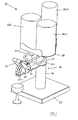
figure 1 is a perspective view of a device according to the present invention; -
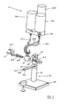
figure 2 is an exploded perspective view of the device offigure 1 ; -
figure 3 shows is an enlarged scale details offigure 2 ; -
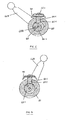
figures 4 and 5 are cross sections of a detail of the device offigure 1 represented in two different operating positions; -
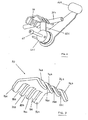
figure 6 is a perspective view of a detail offigure 1 ; -
figure 7 is an enlarged scale of a detail offigure 6 . - In
figures 1 and2 is illustrated a mixing device for beverages generally indicated with 10. Thedevice 10 comprises asupport 20 which in turn comprises abase 22 on which afirst stem 24 is fixed and above it asecond stem 26 is fixed. Asupport plate 28 is fixed at the free end of thesecond stem 26 and, above it, threecontainers 30a,30b,30c are mounted which are filled with beverages of different type depending on the desired mixed beverage. From eachcontainer 30a,30b,30c respectively starts a first, a second and athird delivery duct 32a,32b,32c made of deformable and elastic material such as rubber or the like. - Elastic and deformable material means a material that deforms when it is subjected to a force, and tends to return to its original position when the action of force is finished.
- In the specific case, by applying a pressing force on the
delivery ducts 32a,32b,32c, these are deformed or better yet they are compressed so reducing the passage cross-section of the liquid, while removing the pressing force, the ducts tend to return to their original position due to the elasticity of the material and, thus, the passage cross-section returns to the original one or, at least, to a cross-section very near to the initial one. - An
elongated plate 33 is mounted between thefirst stem 24 and thesecond stem 26, at the free end 33a of which holes 34a,34b,34c are formed in which the free ends of thedelivery ducts 32a,32b,32c are respectively inserted. - Shutting means 40 are mounted on the
elongated plate 33 for adjusting the amount of liquid delivered by each of the threedelivery ducts 32a,32b,32c. - As it can be seen more clearly in
figures 2 and3 , the shutting means 40 comprise a hollowcylindrical support 60 fixed to theelongated plate 33. Apin 42 is coaxially mounted inside thecylindrical support 60 and it is fixed by means of anut 43. A first and a second manoeuvring lever 44a, 44b are rotatably mounted on thepin 42 at both ends of thecylindrical support 60. Moreover, a first, second and third cam 46a,46b,46c having a diamond-shaped profile (visible infigures 4 and 5 ) are rotatably and eccentrically mounted on thepin 42 inside thecylindrical support 60. The first and second cam 46a,46b are fixed to the first manoeuvring lever 44a through a first rod 48a offset with respect to thepin 42, while the third cam 46c is fixed to the second manoeuvring lever 44b by means of a second rod 48b also offset with respect to thepin 42. So, the first manoeuvring lever 44a rotates the first and second cam 46a, 46b, while the second manoeuvring lever 44b rotates the third cam 46c. - From
figures 4 and 5 , it is noted that by rotating the second manoeuvring lever 44b, the third cam 46c rotates and its outer diamond-shaped profile accurately follows the inside circular profile of thecylindrical support 60, namely the profile of the third cam 46c is conjugated with the inside circular profile of thecylindrical support 60. The similar thing happens to the first and second cam 46a,46b. - It is noted that
antifriction spacers 50 are interposed between the cams 46a,46b,46c, and also between the manoeuvring levers 44a,44b and the cams 46a,46c. - A first, second and third through
hole 62a,62b,62c are respectively formed on thecylindrical support 60 at the first, second, third cam 46a,46b,46c. - A first, second and third pressing element or
piston 64a,64b,64c are respectively inserted inside the first, second and third throughhole 62a,62b,62c and they are in contact, on one side, respectively with the first, second and third cam 46a,46b,46c and, on the other side, they respectively act on the first, second andthird delivery duct 32a,32b,32c. - The
pistons 64a,64b,64c have a cylindrical shape and their ends pressing against the delivery ducts are flat. However, the pistons could have other shapes, as well as their ends could be for example a cusp-shaped or spherical. - The shutting means 40 also comprise an abutment element 70 (see
figures 6 and 7 ) fixed on thecylindrical support 60 by means of screws 71a,71b. Theabutment element 70 has a double comb shape, namely a plate 72 provided with four prongs 74a,b,c,d on one side, and with four additional prongs 76a,b,c,d on the opposite side, so as to form three recesses 78a,b,c on one side and other three recesses 80a,b,c on the opposite side, so that the first delivery duct 32a is inserted inside the recesses 78a,80a, the second delivery duct 32b is inserted inside the recesses 78b,80b and, finally, thethird delivery duct 32c is inserted inside the recesses 78c, 80c. Therefore, eachdelivery duct 32a,32b,32c is interposed between theabutment element 70 and respectively one of the threepistons 64a,64b,64c. - The operation of the
device 10 occurs in the following manner. - At the rest position, the two manoeuvring levers 44a,44b are raised, the three cams 46a,46b,46c are arranged as shown in
figure 5 , namely they are in contact with thecylindrical support 60 at the three throughholes 62a,62b,62c, so the threepistons 64a,64b,64c are pushed upwards. Thus, thepistons 64a,64b,64c respectively press against thedelivery ducts 32a,32b,32c which are deformed, so that the inside passage cross-section of eachdelivery duct 32a,32b,32c is completely closed. The threeducts 32a,32b,32c are completely squeezed, thus there is no discharge of liquid. - By operating the second manoeuvring lever 44b and in particular by rotating it downwards, the third cam 46c rotates so the profile of the cam, at the third through
hole 62c, moves away from the inside profile of thecylindrical support 60 and, then, thethird piston 64c is lowered since thethird delivery duct 32c tends to return to its original position due to the elasticity of the material of the duct, as described above, and also due to the weight of thepiston 64c. Thus, the latter pushes less and less against thethird delivery duct 32c. In this way, the inside passage cross-section of the ducts is no longer closed, but opens more and more as the second manoeuvring lever 44b is lowered. When the second lever 44b is completely lowered, the third cam 46c no longer pushes, or only partially, against thethird piston 64c and then against thethird delivery duct 32c, the passage cross-section of the duct has the maximum opening permitted by the third cam 46c and the liquid is free to flow and to exit. - Similarly, by operating the first manoeuvring lever 44a and, in particular, rotating it downwards, the first and second cam 46a,46b rotate, so the profile of the two cams, at the first and second through hole 62a,62b, move away from the inside profile of the
cylindrical support 60 and, then, the first and the second piston 64a,64b are lowered and, as already indicated above, they push less and less against the first and second delivery duct 32a,32b. In this way the inside passage cross-section of the ducts is no longer closed, but it opens more and more as the first manoeuvring lever 44a is lowered. When the first lever 44a is completely lowered, the first and second cam 46a, 46b do not push or they push only partially against the first and second piston 64a,64b and then against the first and second delivery duct 32a,32b, the passage cross-section of the ducts have the maximum opening permitted by the first and second cam 46a, 46b and the liquid is free to flow and come out. - The shutting means 40 are placed in the lower position with respect to the
containers 30a,30b,30c and, in particular, in a position below the bottom of the containers so that the beverages contained therein can flow and come out by gravity as soon as the manoeuvring levers 44a,44b are operated in the open position. - Each cam 46a,46b,46c is shaped according on the type of mixed drink to be made. In particular, if the dosage for each of the three beverages is the same, the three cams will be made with the same profile. If instead the dosages of the beverages are different, then the profiles of the cams will be different and made according to the required dosages.
- Anyway, by simultaneously lowering the two levers in the same manner, the mixed drink is always the same. By further lowering the two levers, the intensity of the output flow is increased and, therefore, the preparation time of the final drink is reduced but the composition remains always the same.
- If instead you want to vary the composition of the final drink, it is possible to lower one of the two levers in a greater or lesser extent depending on the desired amount of each beverage.
- It can be noted, as already previously described, that the device is extremely simple, inexpensive, does not require energy supply to be fed and is extremely reliable.
- The device can be used by anyone, even by inexperienced people, as it is sufficient to lower the two levers at the same extent to obtain always the same mixed drink.
- The cleaning operation occurs simply and quickly because it is sufficient to remove the three
containers 30a,30b,30c and slip off the threedelivery ducts 32a,32b,32c, wash them and finally reassemble them or, simply, flow fresh water to rinse out the containers. - As described above, in order to obtain different mixed drinks, it is sufficient to operate the two manoeuvring levers 44a,44b in a different way, to make the flow of each substance contained in the various containers in different dosages or, if required, to obtain a different drink but operating to the same extent on both the manoeuvring levers, it is sufficient to remove the cams from the pin on which they are mounted and mount cams with a different profile. So, by having different sets of cams, it is possible to obtain different drinks by operating the two manoeuvring levers always in the same way.
- The device may also be composed of only two containers 30a,30b and the first manoeuvring lever 44b operating on the first and second cam 46a,46b.
- In this case, the two cams 46a,46b may have profiles so that:
- 1. varying the position of the manoeuvring element 44a the cross-section of the delivery ducts 32a,32b proportionally varies, so that the ratio of the cross-sections of the two ducts is always the same and, thus, also the intensity of the flow of the two beverages which come out is the same in order to obtain the same cocktail;
- 2. varying the position of the manoeuvring element 44a at predetermined positions, the cross-section of the delivery ducts 32a,32b takes prefixed values, so as to obtain different and specific cocktails for each predetermined position of the manoeuvring element.
- It is clear that any modification which is conceptually or functionally equivalent falls within the scope of the present invention.
- For example, it is possible to have more than three containers from each of which a delivery duct starts with a relative pressing element operated by one or more manoeuvring elements.
- It is also possible that the cams 46a,46b,46c directly act on the
respective delivery ducts 32a,32b,32c, therefore there is no need to use thepistons 64a,64b,64c. Moreover, it is possible to directly act on the pistons by means of push-buttons in place of the cams and the manoeuvring levers. - It is also possible to have a different number of containers, not only two o three, but also four or more containers each provided with a respective delivery duct.
- The device may be provided with means for cooling and/or heating means in order to obtain a mixed cold and/or hot drink.
- It is also possible to add an additional container, in contact with the
containers 30a,30b,30c, inside which ice is put, so as to cool the containers and then the beverages contained therein and, thereby, obtain a mixed cool or cold drink. - The
pistons 64a, 64b, 64c may also be oriented downwards instead of upwards, or rather the pistons may be arranged below the cams 46a,46b,46c. In this case, starting from the condition in which the pistons are lowered and compress the delivery ducts, due to the rotation of the cams, the pistons are raised only because of the elastic return of the material of the ducts, as above explained. - As an alternative to the manual operation, it is possible to have motor means for operating the pressing elements or
pistons 64a,64b,64c. For example, instead of the manoeuvring levers, it is possible to use electric, pneumatic or idraulic actuators.
Claims (8)
- Mixing device (10) for beverages to made alcoholic or non-alcoholic cocktails comprising at least a first and a second container (30a,30b) each able to contain a beverage, at least a first and a second delivery duct (32a,32b) for each of said at least two containers (30a,30b), said delivery ducts (32a,32b) are made of elastic and deformable material for at least a portion thereof, said device (10) comprising shutting means (40) including at least one pressing element (64a,64b) against said portion of elastic and deformable material of each delivery duct (32a,32b) so as to deform said portions of duct to allow or not the passage or not of the beverage in each delivery duct (32a,32b), said device comprising at least one manoeuvring element (44a,44b) which operates said at least one pressing element (64a,64b) and movable between a first initial rest position where said pressing element (64a, 64b) acts on said delivery ducts (32a,32b) so as to close the cross-section of said delivery ducts (32a,32b) preventing the passage of the beverages and a second operative end position where said pressing element (64a,64b) does not act against said delivery ducts (32a,32b) so as to allow the free passage of the beverages, characterized in that said shutting means (40) comprise at least two pressing elements (64a,64b), a first and a second pressing element (64a,64b) which press against respectively said first and second delivery duct (32a,32b), said at least two pressing elements (64a,64b) being distinct and separated to each other in order to independently act on the respective delivery ducts (32a,32b), said at least one manoeuvring element (44a) simultaneously operates said first and second pressing element (64a,64b) which are shaped so that it is possible, by operating on said at least one manoeuvring element (44a), vary continuously and in equal proportion the area of the passage cross-section of each delivery duct (32a,32b), even if the passage area of the two delivery ducts (32a,32b) is different, so as to maintain constant the ratio between the area of the passage cross-section of said first delivery duct (32a,32b) and the area of the passage cross-section of said second delivery duct (32a,32b), so that for any intermediate position between said first initial position and said second final position of said manoeuvring element (44a) a cocktail, with always the same composition, is obtained in which the ratio between the quantities of the two beverages is always the same, even if the quantities of the two beverages are different or it is possible, by operating on said at least one manoeuvring element (44a), to vary the ratio between the area of the passage cross-section of said first delivery duct (32a,32b) and the area of the passage cross-section of said second delivery duct (32a,32b), so that for different positions of said manoeuvring element (44a) a cocktail having different compositions is obtained.
- Device according to claim 1, characterized in that said shutting means (40) comprise at least two rotating cams (46a,46b) one for each of said delivery ducts (32a,32b) which act directly or indirectly against said delivery ducts (32a,32b), said at least two rotating cams (46a,46b) being actuated by said at least one manoeuvring element (44a).
- Device according to claim 2, characterized in that said at least two rotating cams (46a, 46b) have a profile, also different between them, but such that by varying the position of said manoeuvring element (44a) the passage cross-section of each delivery duct (32a,32b) vary of the same proportion, thus maintaining unchanged the ratio between the passage cross-sections of the two delivery ducts (32a,32b) and, therefore, the ratio between the amount of flow that passes in the two delivery ducts (32a, 32b), so as to obtain always the same cocktail in which the ratio of the quantities of the two beverages remains unchanged, even if the quantities of the two beverages are different from each other.
- Device according to claim 2, characterized in that said at least two rotating cams (46a,46b) have a profile, also different between them, and such that in different positions of said manoeuvring element (44a) the ratio of the passage cross-section between said at least two delivery ducts (32a,32b) varies and, therefore, also varies the ratio between the amount of flow which passes in the two delivery ducts (32a,32b), so as to obtain cocktails with different compositions in different positions of said manoeuvring element (44a).
- Device according to claim 2, 3 or 4, characterized in that each of said at least two pressing elements (64a,64b) are made of a pin or piston (64a,64b), each pin or piston (64a,64b) being operated by each of said rotating cams (46a,46b), so that by operating said manoeuvring element (44a), each cam (46a,46b) rotates and said pins or pistons (64a, 64b) press against said delivery duct (32a,32b).
- Device according to claim 2, 3 or 4, characterized in that said at least two rotating cams (46a,46b) directly press against said at least two delivery ducts (32a,32b) to form said at least two pressing elements (64a,64b).
- A device according to any of the previous claims, characterized in that said shutting means (40) comprise at least one abutment element (70), each delivery duct (32a,32b) being inserted between said at least one abutment element (70) and the respective pressing element (64a,64b), so that by moving each pressing element (64a,64b) against said delivery duct (32a,32b), each delivery duct (32a,32b) is compressed between said at least one abutment element (70) and said pressing element (64a, 64b).
- A device according to any of the previous claims, characterized in that said containers (30a,30b,30c) are at least three from each of which respectively starts a first, second and third delivery duct (32a,32b,32c) each provided respectively with a first, second and third pressing element (64a,64b,64c), said at least one manoeuvring elements (44a,44b) are two, a first manoeuvring element (44a) which operates said first and second pressing element (64a,64b) which respectively act on said first and second delivery duct (32a,32b) and a second manoeuvring element (44b) which operates said third pressing element (64c) which acts on said third delivery duct (32c), said manoeuvring elements being controlled simultaneously or independently so as to obtain respectively the same cocktail in which the proportions between the various beverages are always the same, or different cocktails where the proportions between the various beverages can be varied.
Applications Claiming Priority (1)
| Application Number | Priority Date | Filing Date | Title |
|---|---|---|---|
| IT000009A ITVE20120009A1 (en) | 2012-03-07 | 2012-03-07 | LIQUID MIXER DEVICE. |
Publications (1)
| Publication Number | Publication Date |
|---|---|
| EP2636639A1 true EP2636639A1 (en) | 2013-09-11 |
Family
ID=46001589
Family Applications (1)
| Application Number | Title | Priority Date | Filing Date |
|---|---|---|---|
| EP13425037.2A Withdrawn EP2636639A1 (en) | 2012-03-07 | 2013-03-06 | A mixing device for beverages |
Country Status (2)
| Country | Link |
|---|---|
| EP (1) | EP2636639A1 (en) |
| IT (1) | ITVE20120009A1 (en) |
Cited By (3)
| Publication number | Priority date | Publication date | Assignee | Title |
|---|---|---|---|---|
| GB2470660B (en) * | 2009-05-29 | 2015-09-16 | Imi Cornelius Uk Ltd | Apparatus for producing a beverage |
| CN110257210A (en) * | 2019-07-18 | 2019-09-20 | 河北工业大学 | A kind of cocktail brewing device |
| IT202300002430A1 (en) * | 2023-02-13 | 2024-08-13 | Sprizzer Srl | DRINK DISPENSING DEVICE |
Citations (10)
| Publication number | Priority date | Publication date | Assignee | Title |
|---|---|---|---|---|
| US4303222A (en) * | 1980-02-06 | 1981-12-01 | Red Valve Company, Inc. | Pinch valve |
| US4474214A (en) * | 1982-09-02 | 1984-10-02 | Iannelli Frank M | Beverage mixing and dispensing valve |
| CA1179992A (en) * | 1984-02-13 | 1984-12-27 | Bell, Michael | Milk dispenser |
| US4801050A (en) * | 1987-03-23 | 1989-01-31 | Michael Bell | Outlet tube restrictor |
| GB2274326A (en) * | 1993-01-18 | 1994-07-20 | Kodak Ltd | Pinch valve with adjustable reaction member |
| GB2275912A (en) * | 1993-03-11 | 1994-09-14 | P & O Vending Services Limited | Flow control valve for a drink dispenser |
| US5855298A (en) * | 1994-08-18 | 1999-01-05 | Creamiser Products Corporation | Tapping stem for liquid supply container |
| US5901745A (en) * | 1997-06-19 | 1999-05-11 | The Hoover Company | Multi-solution dispensing valve |
| DE20119454U1 (en) * | 2001-11-29 | 2002-02-14 | Aqua Vital Quell- und Mineralwasser GmbH, 41468 Neuss | Beverage dispenser |
| EP1445234A1 (en) * | 2003-02-04 | 2004-08-11 | Conserve Italia Soc. Coop. A.R.L. | An apparatus for dispensing drinks |
-
2012
- 2012-03-07 IT IT000009A patent/ITVE20120009A1/en unknown
-
2013
- 2013-03-06 EP EP13425037.2A patent/EP2636639A1/en not_active Withdrawn
Patent Citations (10)
| Publication number | Priority date | Publication date | Assignee | Title |
|---|---|---|---|---|
| US4303222A (en) * | 1980-02-06 | 1981-12-01 | Red Valve Company, Inc. | Pinch valve |
| US4474214A (en) * | 1982-09-02 | 1984-10-02 | Iannelli Frank M | Beverage mixing and dispensing valve |
| CA1179992A (en) * | 1984-02-13 | 1984-12-27 | Bell, Michael | Milk dispenser |
| US4801050A (en) * | 1987-03-23 | 1989-01-31 | Michael Bell | Outlet tube restrictor |
| GB2274326A (en) * | 1993-01-18 | 1994-07-20 | Kodak Ltd | Pinch valve with adjustable reaction member |
| GB2275912A (en) * | 1993-03-11 | 1994-09-14 | P & O Vending Services Limited | Flow control valve for a drink dispenser |
| US5855298A (en) * | 1994-08-18 | 1999-01-05 | Creamiser Products Corporation | Tapping stem for liquid supply container |
| US5901745A (en) * | 1997-06-19 | 1999-05-11 | The Hoover Company | Multi-solution dispensing valve |
| DE20119454U1 (en) * | 2001-11-29 | 2002-02-14 | Aqua Vital Quell- und Mineralwasser GmbH, 41468 Neuss | Beverage dispenser |
| EP1445234A1 (en) * | 2003-02-04 | 2004-08-11 | Conserve Italia Soc. Coop. A.R.L. | An apparatus for dispensing drinks |
Cited By (5)
| Publication number | Priority date | Publication date | Assignee | Title |
|---|---|---|---|---|
| GB2470660B (en) * | 2009-05-29 | 2015-09-16 | Imi Cornelius Uk Ltd | Apparatus for producing a beverage |
| CN110257210A (en) * | 2019-07-18 | 2019-09-20 | 河北工业大学 | A kind of cocktail brewing device |
| CN110257210B (en) * | 2019-07-18 | 2023-12-12 | 河北工业大学 | Cocktail brewing device |
| IT202300002430A1 (en) * | 2023-02-13 | 2024-08-13 | Sprizzer Srl | DRINK DISPENSING DEVICE |
| WO2024171054A1 (en) * | 2023-02-13 | 2024-08-22 | Sprizzer Srl | Device for dispensing beverages |
Also Published As
| Publication number | Publication date |
|---|---|
| ITVE20120009A1 (en) | 2013-09-08 |
Similar Documents
| Publication | Publication Date | Title |
|---|---|---|
| US4228930A (en) | Dispensing pump | |
| US20120298694A1 (en) | Metering dispenser | |
| US5400614A (en) | Frozen dessert apparatus | |
| US6119905A (en) | Hand-actuated dispensing tap for ice-cream machines | |
| JP2021020743A (en) | Beverage dispensing system | |
| EP2682193B1 (en) | Dispenser | |
| US8157117B2 (en) | Locking mechanism for the cover for a drink dispensing machine | |
| EP2925665B1 (en) | Beverage dispensing system | |
| CA2029973A1 (en) | Fluid food dispenser | |
| EP1607700A3 (en) | Freezer having water dispenser with measured dosing | |
| CA2784875C (en) | Beverage-preparation device provided with a liquid distributor | |
| ITVE20120009A1 (en) | LIQUID MIXER DEVICE. | |
| GB2313106A (en) | Serving wine | |
| GB2470660A (en) | Apparatus for consistently mixing and dispensing a beverage | |
| CN1973740B (en) | Apparatus consisting of several dispensing assemblies for the automatic preparation and dispensing of espresso | |
| AT389865B (en) | OUTPUT DEVICE | |
| US2755006A (en) | Drink dispensing mechanism | |
| EP0339110B1 (en) | Automatic drink dispenser | |
| EP2039649A1 (en) | Post-mix beverage dispenser with dosing pump | |
| CN220641736U (en) | Ice powder production device convenient for batching | |
| CN223561266U (en) | Cold filling production mechanism for coconut water production | |
| US1681866A (en) | Dispensing pump | |
| DE1532658B (en) | Drink dispenser for serving mixed drinks | |
| WO2003086950A2 (en) | Dispenser for liquid foodstuffs | |
| EP4665674A1 (en) | Device for dispensing beverages |
Legal Events
| Date | Code | Title | Description |
|---|---|---|---|
| PUAI | Public reference made under article 153(3) epc to a published international application that has entered the european phase |
Free format text: ORIGINAL CODE: 0009012 |
|
| AK | Designated contracting states |
Kind code of ref document: A1 Designated state(s): AL AT BE BG CH CY CZ DE DK EE ES FI FR GB GR HR HU IE IS IT LI LT LU LV MC MK MT NL NO PL PT RO RS SE SI SK SM TR |
|
| AX | Request for extension of the european patent |
Extension state: BA ME |
|
| STAA | Information on the status of an ep patent application or granted ep patent |
Free format text: STATUS: THE APPLICATION IS DEEMED TO BE WITHDRAWN |
|
| 18D | Application deemed to be withdrawn |
Effective date: 20140312 |