EP2635921B1 - Tri-material dual-species neutron spectrometer - Google Patents
Tri-material dual-species neutron spectrometer Download PDFInfo
- Publication number
- EP2635921B1 EP2635921B1 EP11838354.6A EP11838354A EP2635921B1 EP 2635921 B1 EP2635921 B1 EP 2635921B1 EP 11838354 A EP11838354 A EP 11838354A EP 2635921 B1 EP2635921 B1 EP 2635921B1
- Authority
- EP
- European Patent Office
- Prior art keywords
- plate
- detectors
- neutron
- scintillation
- gamma
- Prior art date
- Legal status (The legal status is an assumption and is not a legal conclusion. Google has not performed a legal analysis and makes no representation as to the accuracy of the status listed.)
- Not-in-force
Links
Images


Classifications
-
- G—PHYSICS
- G01—MEASURING; TESTING
- G01T—MEASUREMENT OF NUCLEAR OR X-RADIATION
- G01T1/00—Measuring X-radiation, gamma radiation, corpuscular radiation, or cosmic radiation
- G01T1/16—Measuring radiation intensity
- G01T1/20—Measuring radiation intensity with scintillation detectors
- G01T1/2008—Measuring radiation intensity with scintillation detectors using a combination of different types of scintillation detectors, e.g. phoswich
-
- G—PHYSICS
- G01—MEASURING; TESTING
- G01T—MEASUREMENT OF NUCLEAR OR X-RADIATION
- G01T1/00—Measuring X-radiation, gamma radiation, corpuscular radiation, or cosmic radiation
- G01T1/16—Measuring radiation intensity
- G01T1/20—Measuring radiation intensity with scintillation detectors
-
- G—PHYSICS
- G01—MEASURING; TESTING
- G01T—MEASUREMENT OF NUCLEAR OR X-RADIATION
- G01T1/00—Measuring X-radiation, gamma radiation, corpuscular radiation, or cosmic radiation
- G01T1/16—Measuring radiation intensity
- G01T1/20—Measuring radiation intensity with scintillation detectors
- G01T1/203—Measuring radiation intensity with scintillation detectors the detector being made of plastics
-
- G—PHYSICS
- G01—MEASURING; TESTING
- G01T—MEASUREMENT OF NUCLEAR OR X-RADIATION
- G01T3/00—Measuring neutron radiation
- G01T3/06—Measuring neutron radiation with scintillation detectors
-
- G—PHYSICS
- G01—MEASURING; TESTING
- G01T—MEASUREMENT OF NUCLEAR OR X-RADIATION
- G01T3/00—Measuring neutron radiation
- G01T3/06—Measuring neutron radiation with scintillation detectors
- G01T3/065—Spectrometry
-
- G—PHYSICS
- G01—MEASURING; TESTING
- G01T—MEASUREMENT OF NUCLEAR OR X-RADIATION
- G01T7/00—Details of radiation-measuring instruments
Definitions
- This invention relates to an imaging neutron spectrometer and, in particular, a spectrometer for real-time neutron source location and identification.
- Neutrons are, by their nature, resistant to detection, and defy easy imaging and spectroscopy. Detection has mostly been in the form of registering moderated or thermalized neutrons from a fast neutron source. Because one only measures the charged particles produced by a neutron interaction, deducing the properties of the parent neutron is ambiguous, besides being difficult.
- Registering moderated neutrons comes without any information about the incident direction or energy. Measuring fast neutrons in a bulk detector provides a compromised energy measurement, but still lacks directional information.
- a double-scatter telescope pays the penalties of greatly increased complexity and low efficiency by requiring two neutron scatters, but it benefits in the end because the elastic scatter kinematics can be used to constrain the incident velocity vector while simultaneously performing a quality energy measurement.
- US 7741613 discloses a system for measuring neutrons comprising parallel plates carrying scintillation detectors connected to a processing unit.
- a system for imaging and measuring neutrons, the system comprising: a frame; a first plate having a first plurality of plastic scintillation detectors and a second plate having a second plurality of stilbene scintillation detectors, which plates are parallel to each other and carried by the frame; an electronic and processing unit; characterised in that the system is further configured for imaging and measuring gamma rays; the first plurality of scintillation detectors are distributed over the first plate and configured to detect at least one of a neutron and a gamma ray; the second plurality of scintillation detectors are distributed over the second plate and configured to detect the at least one of a neutron and a gamma ray; and the system further comprises: a third plate carried by the frame wherein the third plate is parallel to the first plate and the second plate; and a third plurality of scintillation detectors distributed over the third plate, the third plurality of scintillation
- the inorganic scintillation detectors of the third plurality of scintillation detectors may comprise sodium iodide.
- the system is portable.
- an imaging neutron spectrometer 20 is shown.
- the system is capable of imaging and measuring both neutron and gamma sources remotely. Remotely imaging and measuring in the present system is done without touching the source.
- the spectrometer 20 has a frame 22 and three parallel detecting plates or planes 24, 26, and 28, and an electronic and processing unit 30.
- the preferred embodiment of system 20 is designed to be portable as described below in more detail.
- the detecting plates or planes 24, 26, and 28 are each parallel to each other. Each panel has a plurality of detectors 34. Each detector 34 is a scintillation detector. A scintillation detector or counter 34 produces a flash of light (scintillation) in a fluorescent material by an ionizing radiation which is detected and counted by a multiplier phototube and associated circuits 30.
- Each of the detecting plates 24, 26, and 28 has detectors 34 which are different from those of other plates and performs the detectors 34 own special function.
- the three plates 24, 26, and 28 form a stack in which MeV-range nuclear neutron and gamma radiation can be detected.
- the detectors 34 of the first plate 24 have a plastic scintillator that acts as part of the neutron imaging system and to a much lesser degree the gamma imaging system.
- the detectors 34 of the second plate 26 employ stilbene [C 6 H 5 CH: CHC 6 H 5 ] that possesses pulse-shape- discrimination (PSD) properties. Neutrons are scattered first in the first plate 24 by the plastic scintillator detectors 34 and then further scattered in the second plate 26 by the stilbene detectors 34 in a double-scatter arrangement.
- the PSD signal from the stilbene is used preferentially to select neutron interactions.
- the present invention in contrast to conventional two plate arrangements of the stilbene detectors 34 of the second plate 26 and plastic scintillator detectors 34 of the first plate 24, allows the system to be used also for the gamma imaging.
- the gamma imaging uses the second plate 26, with the stilbene detectors 34, and the third plate 28.
- Each of the detectors 34 of the third plate 28 is an inorganic scintillator.
- the detector is sodium iodide (NaI).
- the second plate 26 with the stilbene detectors 34 is a key component of the gamma imaging system, providing the necessary PSD measurement to maximize signal to noise for both detection systems.
- the stilbene detectors 34 of the second plate 26 are shared by the gamma and neutron imaging systems.
- the stilbene provides the neutron/gamma identification to maximize the signal to noise ratio for both systems.
- the system uses solid scintillators in contrast to liquid scintillators such as mineral oil. The solid scintillators allow for a more rugged portable system 20.
- the three parallel detecting plates 24, 26, and 28 each have a plurality of detectors 34.
- the same style detector 34 is used throughout the plate, but is different from the detectors in the other plates.
- the order of detectors 34 from top to bottom is plastic scintillator, stilbene, and inorganic scintillator 34.
- the actual neutron measurements employ the scintillation amplitude in the plastic scintillators and the time-of-flight from the plastic to the stilbene detectors.
- a gamma signal in the stilbene can be used to reject events.
- the gamma measurements use the scintillation amplitude in both the stilbene and the inorganic scintillators with the time-of-flight used to reject neutrons.
- a neutron signal in the stilbene would be required to accept an event.
- An event occurs when there is a signal in at least two of the three detecting planes.
- the system 20 is capable of measuring both neutrons and gamma rays.
- the neutron and gamma emissions are related and can be used together for increased knowledge of the source of radiation environment.
- the system 20 is a pair of double scatter cameras.
- the first plate 24 and the second plate 26 are the double scatter camera for the neutrons.
- the second plate 26 and the third plate 28 are the double scatter camera for the gamma emissions.
- a neutron or a gamma the idea is that a particle scatters once in a forward detector after which it sometimes scatters in a rearward detector.
- a neutron or a gamma can pass through any of these detectors 34 without any interaction. These particles interact in a probabilistic fashion.
- the thickness of these detectors is selected to be thick enough to register a reasonable fraction of particles, but not so thick that they interact twice.
- the ideal scattering or detection medium for neutrons the detectors 34 in the second plate 26, also happens to be an excellent forward scatterer for gamma rays.
- a material is an organic substance rich in hydrogen.
- the neutron energy is measured by summing the energy the neutron deposits in the forward detector and the energy of the recoiling neutron measured by the travel time to the rearward detector.
- the situation for gamma rays is different in that all gamma rays travel with the same speed, so that no energy information is gleaned from time-of-flight. Instead, one must capture the gamma ray in entirety, requiring a thick detector, typically made of a dense inorganic scintillator, such as the detector 34 in the third plate 28.
- the hydrogen content of a gamma-ray detector is not important. It must just be thicker than the interaction length of the gamma ray in that medium.
- the neutron scatter camera of the system 20 has two plates of organic scintillation detectors; the first plate 24 and the second plate 26.
- the third plate 28 has high density inorganic scintillators.
- the middle plate 26 with the stilbene scintillators serves as the rearward scatterer for the neutron camera and the forward scatterer for the gamma camera, thereby providing a dual species camera.
- a neutron camera comprised of all organic scintillation detectors can detect gamma rays, it is done with greatly compromised quality. Similarly, a traditional gamma camera can detect neutrons but inefficiently and with compromised resolution.
- the detectors 34 in a preferred embodiment use solid organics such as plastic and stilbene in the first two plates instead of a liquid such as mineral oil. This is because of ruggedness requirements for field work.
- the second attribute is that of so-called pulse shape discrimination (PSD), meaning that the nanosecond shape of the signal from the detectors can be used to identify whether the scattering particle is a gamma ray or a neutron. It is very beneficial to have at least one plate of either type of camera comprised of scintillation detectors with this property.
- the system 20 is designed with the material in the detectors 34 of the first plane 24 being a plastic scintillator with no pulse shape discrimination properties.
- the detectors 34 of the second plane 26, which serve both the neutron and gamma cameras, are comprised of an organic crystal, called stilbene. Stilbene possesses pulse shape discrimination properties.
- the detectors 34 of the third plane 28 are comprised of an inorganic crystal, such as NaI, that does not possess PSD.
- the complete system 20 has optimized sensitivity for both species of particles, while minimizing the total amount of hardware and the electronics. Being all in the solid state it can be made rugged and still possess excellent resolution and sensitivity for both species.
- Neutrons have no charge, and therefore do not readily interact. Thus, neutrons must be detected by indirect methods.
- a preferred method for neutron detection at MeV energies exploits the large elastic n-p scattering cross section.
- the choice material, serving the functions of neutron scatterer and recoil proton detector, is an organic scintillator. This material consists of mainly hydrogen and carbon, in the number ratio of 1.0 to 2.0. The relative concentration of hydrogen varies with scintillator type.
- an incident neutron must undergo an n-p scatter in each of two detectors. One must be able to follow the path of the neutron once it enters the instrument, measuring the location, relative time, and energy deposits of each n-p interaction.
- FIG. 2 a schematic view of neutron double-scatter kinematics is shown.
- a neutron 46 whose incident direction is unknown, undergoes two n-p scatters by detection by detectors 34, such as shown in FIG. 1 , to obtain information regarding the source.
- the energy and direction i.e., momentum vector
- the energy of the incident neutron as well as the scatter angle can be computed.
- the detectors 34 in the first plate 24 are made up of 1 inch cylindrical cells of plastic scintillator, read out by fast, rugged 1 inch photo multiple tubes (PMT).
- the detectors on the second and third layer are likewise made up of 1 inch cells read out by similar PMTs.
- the second plate 26 is stilbene and the third plate 28 is inorganic such as sodium iodide (NaI).
- the detectors 34 on the second plate 26 are capable of pulse-shape-discrimination (PSD). Pulse shape discrimination (and Time-of-Flight (ToF)) allows the system to reject or distinguish gamma rays, important for high background environments.
- Time-of-flight measurements are made between plates 24, 26 and 28. All cells or detectors 34 represent independent data channels. When a neutron interacts with a detector 34 in the first plate 24 analog signals from that detector plate are generated from the analog sum of the different cells in first plate 24. Those signals initiate the ToF measurement, create a fast logic signal to test for time coincidence with what happens in the second plate 26, and serve as an analog pulse height for the energy deposited by the neutron in the first plate 24. The cell identification is taken to be the interaction location, i.e., a spatial resolution of 1 inch corresponding to a particular detector. Multiple signals from different detectors 34 in the first plate 24 are rejected.
- the stilbene detectors 34 an organic scintillator, of the second plate 26 possesses pulse-shape-discrimination properties. This property of the scintillator produces analog signals that can be used to identify whether the ionizing particle is either fast (electron, muon) or slow (proton or heavy ion).
- the two types of particles differ in their detailed pulse shape - a function of the chemistry of the scintillator. Neutron-initiated events can thus be identified and selected for further data analysis. Electron ionization pulse shapes are generally discarded.
- the two plates 24 and 26 are separated by 30 cm, scintillator to scintillator.
- a gamma ray over this distance registers a 1 ns ToF, while a 1-MeV neutron requires ⁇ 30 ns to cover the same distance.
- Oblique trajectories yield longer ToF values, but this effect is corrected with the event location information provided by the cell identifications.
- the ToF range is of order 50 ns, extending above and below typical fast neutron speeds. By having a longer ToF range, one automatically obtains a measure of the accidental coincidence rate - an important measurement in hot radiation environments.
- the system 20 is designed to be portable. In an embodiment, the system 20 is designed to operate eight hours on battery power with each plate populated with 77 detector cells. Referring back to FIG. 1 , a battery pack 38 is carried by the frame 22. Analog data are processed in an on-board computer, which is part of the electronic and processing unit 30, digitized and formatted for transmission to a remote computer for real-time monitoring or analysis and/or data archiving.
- the connection between the on-board and remote computers can be by ethernet cable or wireless communications.
- the instrument is controlled through the remote computer, nominally a laptop computer running LabVIEWTM marketed by National Instruments.
- the remote computer also monitors many housekeeping parameters, such as temperature, voltages, count rates in all detector cells and other rates, important for assessing instrument behavior and performance. Gains in the photo multiple tubes (PMTs) are commandable.
- the detector cell plates are sprung to absorb shock during transit.
- a prototype of the system 20 was built with three cells in each plate.
- a test of the system 20 to measure neutrons with the first plate 24 and the second plate 26 was also (1) a test of the performance on the electronics for each plate simultaneously to process signals from multiple cells and (2) a test of the ability to trim the gains and thresholds of six cells, so that they acted like a single instrument with minimal dispersion in the spectrum and image because of gain and threshold variations.
- the nine cell-pair combinations in the first two plates 24 and 26 should behave as one when each cell is properly adjusted and trimmed.
- a 252 Cf source was placed on axis at a distance of 3.4m.
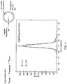
- FIG. 3 a graph of system response to 252 Cf (Californium) is shown.
- a graph of angular resolution is shown in FIG. 4 and particularly an angular resolution measurement (ARM) for the 3x3 cumulative combination is shown.
- the neutron trajectory for each combination of cells is different and each kinematically measured scattered angle must agree with the scatter angle measured by simple geometry.
- the ARM function is the difference of those two angles per neutron event.
- the width of this distribution is ⁇ 12° (FWHM), somewhat larger than that measured with only two cells (10° FWHM). This is probably due to small variations in the gains of the detectors 34 in the first plate 24 or the time-of flight (ToF) calibrations.
- FWHM ⁇ 12°
- the non-gaussian wings on the ARM distribution arise from neutron events near the threshold of detection, i.e., 50 keV ee in either the first plate 24 or the second plate 26, as seen in FIG. 1 ., or equivalently neutrons from approximately 300 keV to 700 keV.
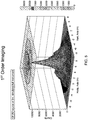
- a strong central peak in FIG. 5 is present in the image plate corresponding to true location of the source. However, there is considerable structure outside the central peak. This structure arises from the correlated circle intersections from the presence of a point source. They are most apparent when the number of cell pairs is small, i.e., nine in our case. With a fully populated instrument, the cell pair count grows to 5900 and these lobes or ghost images will disperse, while the central peak grows in proportion to the effective area, i.e., proportional to the number of cell pairs.
- This system or instrument 20 is particularly useful in mixed radiation environments, but typically neutron environments are also rich in gamma rays.
- the motivating application is for security use, either by the DoD or DHS or any number of agencies responsible for identifying fissile or radioactive material.
- One example is a state police force responsible for monitoring or screening traffic in and out of a major city.
- nuclear power industry could also find a dual species instrument useful for monitoring nuclear fuel and any associated gamma-ray emission.
- the DHS use envisioned is one where a neutron emitting quantity of material is cloaked in other materials.
- a dual species camera can not only identify the source of the neutron emission but also identify the gamma-ray emission induced by the presence of neutrons.
- the gamma-ray emission carries with it signatures of the material cloaking the neutron source, e.g., plutonium.
- the most exciting example is that the neutron emission excites nitrogen nuclei in surrounding high explosives (rich in nitrogen). The neutrons may not be seen directly, but the characteristic signatures of nitrogen excitation can still be detected. Any agent could have additional information, not only of the neutron source but also of the surrounding material.
- the detectors of the second and third plates are preferred for detecting gamma rays, it is recognized that the detectors of the first and third plates can be used.
- the efficiency of the system is not as high as the embodiment discussed above.
- first plate with stilbene detectors or other detectors that possess PSD properties could be used with a second plate having both plastic and inorganic detectors.
- the detectors in the first plate would then provide PSD for both neutron and gamma detection.
Landscapes
- Physics & Mathematics (AREA)
- Spectroscopy & Molecular Physics (AREA)
- Health & Medical Sciences (AREA)
- Life Sciences & Earth Sciences (AREA)
- General Physics & Mathematics (AREA)
- High Energy & Nuclear Physics (AREA)
- Molecular Biology (AREA)
- Measurement Of Radiation (AREA)
Description
- This invention relates to an imaging neutron spectrometer and, in particular, a spectrometer for real-time neutron source location and identification.
- There are several applications for conventional neutron imager/spectrometers. However, all applications revolve around detecting, locating, monitoring, and identifying nuclear material.
- Neutrons are, by their nature, resistant to detection, and defy easy imaging and spectroscopy. Detection has mostly been in the form of registering moderated or thermalized neutrons from a fast neutron source. Because one only measures the charged particles produced by a neutron interaction, deducing the properties of the parent neutron is ambiguous, besides being difficult.
- Registering moderated neutrons comes without any information about the incident direction or energy. Measuring fast neutrons in a bulk detector provides a compromised energy measurement, but still lacks directional information. A double-scatter telescope pays the penalties of greatly increased complexity and low efficiency by requiring two neutron scatters, but it benefits in the end because the elastic scatter kinematics can be used to constrain the incident velocity vector while simultaneously performing a quality energy measurement.
-
US 7741613 discloses a system for measuring neutrons comprising parallel plates carrying scintillation detectors connected to a processing unit. - According to the invention there is provided a system, as defined in
claim 1, for imaging and measuring neutrons, the system comprising: a frame; a first plate having a first plurality of plastic scintillation detectors and a second plate having a second plurality of stilbene scintillation detectors, which plates are parallel to each other and carried by the frame; an electronic and processing unit; characterised in that the system is further configured for imaging and measuring gamma rays; the first plurality of scintillation detectors are distributed over the first plate and configured to detect at least one of a neutron and a gamma ray; the second plurality of scintillation detectors are distributed over the second plate and configured to detect the at least one of a neutron and a gamma ray; and the system further comprises: a third plate carried by the frame wherein the third plate is parallel to the first plate and the second plate; and a third plurality of scintillation detectors distributed over the third plate, the third plurality of scintillation detectors configured to detect the at least one of a neutron and a gamma ray, the third plurality of scintillation detectors comprising inorganic scintillation detectors; and the electronic and processing unit is electronically connected to the first plurality of scintillation detectors, the second plurality of scintillation detectors, and the third plurality of scintillation detectors, wherein the detectors detect the neutron and the electronic and processing unit are configured to determine a path of the neutron based on an interaction with one of the detectors of the first plate and then an interaction with one of the detectors of the second plate; and wherein the detectors detect the gamma ray and the electronic and processing unit are configured to determine a path of the gamma ray based on interaction with one of the detectors of the second plate and then an interaction with one of the detectors of the third plate. - The inorganic scintillation detectors of the third plurality of scintillation detectors may comprise sodium iodide.
- Preferably the system is portable.
- The foregoing and other objects, features, and advantages of the invention will be apparent from the following description of particular embodiments of the invention, as illustrated in the accompanying drawings in which like reference characters refer to the same parts throughout the different views. The drawings are not necessarily to scale, emphasis instead being placed upon illustrating the principles of the invention.
-
FIG. 1 is a perspective view of an imaging neutron spectrometer system; -
FIG. 2 is a schematic view of neutron double-scatter kinematics; -
FIG. 3 is a graph of system response to 252Cf (Californium); -
FIG. 4 is a graph of angular resolution; -
FIG. 5 . is a graph of 1 st order imaging of a 252Cf source at 3 meters; -
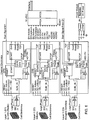
FIG. 6 is a block diagram of the three plane system. - Referring to
FIG. 1 , animaging neutron spectrometer 20 is shown. The system is capable of imaging and measuring both neutron and gamma sources remotely. Remotely imaging and measuring in the present system is done without touching the source. - The
spectrometer 20 has aframe 22 and three parallel detecting plates orplanes processing unit 30. The preferred embodiment ofsystem 20 is designed to be portable as described below in more detail. - The detecting plates or
planes detectors 34. Eachdetector 34 is a scintillation detector. A scintillation detector orcounter 34 produces a flash of light (scintillation) in a fluorescent material by an ionizing radiation which is detected and counted by a multiplier phototube and associatedcircuits 30. - Each of the detecting
plates detectors 34 which are different from those of other plates and performs thedetectors 34 own special function. - The three
plates detectors 34 of thefirst plate 24 have a plastic scintillator that acts as part of the neutron imaging system and to a much lesser degree the gamma imaging system. Thedetectors 34 of thesecond plate 26 employ stilbene [C6H5CH: CHC6H5] that possesses pulse-shape- discrimination (PSD) properties. Neutrons are scattered first in thefirst plate 24 by theplastic scintillator detectors 34 and then further scattered in thesecond plate 26 by thestilbene detectors 34 in a double-scatter arrangement. The PSD signal from the stilbene is used preferentially to select neutron interactions. - The present invention, in contrast to conventional two plate arrangements of the
stilbene detectors 34 of thesecond plate 26 andplastic scintillator detectors 34 of thefirst plate 24, allows the system to be used also for the gamma imaging. The gamma imaging uses thesecond plate 26, with thestilbene detectors 34, and thethird plate 28. Each of thedetectors 34 of thethird plate 28 is an inorganic scintillator. In a preferred embodiment, the detector is sodium iodide (NaI). - The
second plate 26 with thestilbene detectors 34 is a key component of the gamma imaging system, providing the necessary PSD measurement to maximize signal to noise for both detection systems. - The
stilbene detectors 34 of thesecond plate 26 are shared by the gamma and neutron imaging systems. The stilbene provides the neutron/gamma identification to maximize the signal to noise ratio for both systems. As indicated above, the system uses solid scintillators in contrast to liquid scintillators such as mineral oil. The solid scintillators allow for a more ruggedportable system 20. - As indicated above, the three
parallel detecting plates detectors 34. Thesame style detector 34 is used throughout the plate, but is different from the detectors in the other plates. The order ofdetectors 34 from top to bottom (i.e., first plate to third plate) is plastic scintillator, stilbene, andinorganic scintillator 34. - The actual neutron measurements employ the scintillation amplitude in the plastic scintillators and the time-of-flight from the plastic to the stilbene detectors. A gamma signal in the stilbene can be used to reject events. The gamma measurements use the scintillation amplitude in both the stilbene and the inorganic scintillators with the time-of-flight used to reject neutrons. A neutron signal in the stilbene would be required to accept an event. An event occurs when there is a signal in at least two of the three detecting planes.
- As indicated above, the
system 20 is capable of measuring both neutrons and gamma rays. The neutron and gamma emissions are related and can be used together for increased knowledge of the source of radiation environment. Thesystem 20 is a pair of double scatter cameras. Thefirst plate 24 and thesecond plate 26 are the double scatter camera for the neutrons. Thesecond plate 26 and thethird plate 28 are the double scatter camera for the gamma emissions. Whether it be a neutron or a gamma, the idea is that a particle scatters once in a forward detector after which it sometimes scatters in a rearward detector. A neutron or a gamma can pass through any of thesedetectors 34 without any interaction. These particles interact in a probabilistic fashion. The thickness of these detectors is selected to be thick enough to register a reasonable fraction of particles, but not so thick that they interact twice. - The difference between the two double scatter cameras is that the ideal scattering or detection medium for neutrons, the
detectors 34 in thesecond plate 26, also happens to be an excellent forward scatterer for gamma rays. Such a material is an organic substance rich in hydrogen. Thus, for a neutron camera, one constitutes the camera with an organic scintillator for both the forward and rearward scatterers. The neutron energy is measured by summing the energy the neutron deposits in the forward detector and the energy of the recoiling neutron measured by the travel time to the rearward detector. - The situation for gamma rays is different in that all gamma rays travel with the same speed, so that no energy information is gleaned from time-of-flight. Instead, one must capture the gamma ray in entirety, requiring a thick detector, typically made of a dense inorganic scintillator, such as the
detector 34 in thethird plate 28. The hydrogen content of a gamma-ray detector is not important. It must just be thicker than the interaction length of the gamma ray in that medium. - The neutron scatter camera of the
system 20 has two plates of organic scintillation detectors; thefirst plate 24 and thesecond plate 26. - In that it is preferred for gamma ray detection to have an
inorganic scintillation detector 34, thethird plate 28 has high density inorganic scintillators. Themiddle plate 26 with the stilbene scintillators serves as the rearward scatterer for the neutron camera and the forward scatterer for the gamma camera, thereby providing a dual species camera. - While a neutron camera comprised of all organic scintillation detectors can detect gamma rays, it is done with greatly compromised quality. Similarly, a traditional gamma camera can detect neutrons but inefficiently and with compromised resolution.
- The
detectors 34 in a preferred embodiment use solid organics such as plastic and stilbene in the first two plates instead of a liquid such as mineral oil. This is because of ruggedness requirements for field work. The second attribute is that of so-called pulse shape discrimination (PSD), meaning that the nanosecond shape of the signal from the detectors can be used to identify whether the scattering particle is a gamma ray or a neutron. It is very beneficial to have at least one plate of either type of camera comprised of scintillation detectors with this property. - The
system 20 is designed with the material in thedetectors 34 of thefirst plane 24 being a plastic scintillator with no pulse shape discrimination properties. Thedetectors 34 of thesecond plane 26, which serve both the neutron and gamma cameras, are comprised of an organic crystal, called stilbene. Stilbene possesses pulse shape discrimination properties. Finally, thedetectors 34 of thethird plane 28 are comprised of an inorganic crystal, such as NaI, that does not possess PSD. - The
complete system 20 has optimized sensitivity for both species of particles, while minimizing the total amount of hardware and the electronics. Being all in the solid state it can be made rugged and still possess excellent resolution and sensitivity for both species. - With the
system 20 described, some of the underlying theory is described. Neutrons have no charge, and therefore do not readily interact. Thus, neutrons must be detected by indirect methods. A preferred method for neutron detection at MeV energies exploits the large elastic n-p scattering cross section. The choice material, serving the functions of neutron scatterer and recoil proton detector, is an organic scintillator. This material consists of mainly hydrogen and carbon, in the number ratio of 1.0 to 2.0. The relative concentration of hydrogen varies with scintillator type. - To perform imaging, an incident neutron must undergo an n-p scatter in each of two detectors. One must be able to follow the path of the neutron once it enters the instrument, measuring the location, relative time, and energy deposits of each n-p interaction.
- Referring to
FIG. 2 , a schematic view of neutron double-scatter kinematics is shown. Aneutron 46, whose incident direction is unknown, undergoes two n-p scatters by detection bydetectors 34, such as shown inFIG. 1 , to obtain information regarding the source. By measuring the spatial coordinates of the two interactions and time of flight (ToF), the energy and direction (i.e., momentum vector) of the scattered neutron is determined. By measuring the energy of the first recoil proton, the energy of the incident neutron as well as the scatter angle can be computed. - With this information one can constrain the incident neutron direction to lie on the
mantle 48 of acone 50 about the recoil neutron velocity (as seen inFIG. 2 ). The scatter angle sin2θ = Ep/En. By projecting thecone 50 onto an object plane or sphere, one has anevent circle 52 for each event, also shown inFIG. 2 . From the intersection of multiple event circles, through statistical means it is possible to obtain an image of a neutron source. - Still referring to
FIG. 2 , in a preferred embodiment thedetectors 34 in thefirst plate 24 are made up of 1 inch cylindrical cells of plastic scintillator, read out by fast, rugged 1 inch photo multiple tubes (PMT). The detectors on the second and third layer are likewise made up of 1 inch cells read out by similar PMTs. In contrast to the plastic scintillator of thefirst plate 24, thesecond plate 26 is stilbene and thethird plate 28 is inorganic such as sodium iodide (NaI). Thedetectors 34 on thesecond plate 26 are capable of pulse-shape-discrimination (PSD). Pulse shape discrimination (and Time-of-Flight (ToF)) allows the system to reject or distinguish gamma rays, important for high background environments. - With some of the underlying theory described, the method of detection, as shown in the block diagram of
FIG. 6 , is described. Time-of-flight measurements are made betweenplates detectors 34 represent independent data channels. When a neutron interacts with adetector 34 in thefirst plate 24 analog signals from that detector plate are generated from the analog sum of the different cells infirst plate 24. Those signals initiate the ToF measurement, create a fast logic signal to test for time coincidence with what happens in thesecond plate 26, and serve as an analog pulse height for the energy deposited by the neutron in thefirst plate 24. The cell identification is taken to be the interaction location, i.e., a spatial resolution of 1 inch corresponding to a particular detector. Multiple signals fromdifferent detectors 34 in thefirst plate 24 are rejected. - Similar signal processing takes place in the
second plate 26, where the sum signal stops the ToF measurement and the cells that trigger are identified and recorded. - The
stilbene detectors 34, an organic scintillator, of thesecond plate 26 possesses pulse-shape-discrimination properties. This property of the scintillator produces analog signals that can be used to identify whether the ionizing particle is either fast (electron, muon) or slow (proton or heavy ion). The two types of particles differ in their detailed pulse shape - a function of the chemistry of the scintillator. Neutron-initiated events can thus be identified and selected for further data analysis. Electron ionization pulse shapes are generally discarded. - In a preferred embodiment, the two
plates order 50 ns, extending above and below typical fast neutron speeds. By having a longer ToF range, one automatically obtains a measure of the accidental coincidence rate - an important measurement in hot radiation environments. - As indicated above, in one embodiment the
system 20 is designed to be portable. In an embodiment, thesystem 20 is designed to operate eight hours on battery power with each plate populated with 77 detector cells. Referring back toFIG. 1 , abattery pack 38 is carried by theframe 22. Analog data are processed in an on-board computer, which is part of the electronic andprocessing unit 30, digitized and formatted for transmission to a remote computer for real-time monitoring or analysis and/or data archiving. The connection between the on-board and remote computers can be by ethernet cable or wireless communications. - The instrument is controlled through the remote computer, nominally a laptop computer running LabVIEW™ marketed by National Instruments. The remote computer also monitors many housekeeping parameters, such as temperature, voltages, count rates in all detector cells and other rates, important for assessing instrument behavior and performance. Gains in the photo multiple tubes (PMTs) are commandable. The detector cell plates are sprung to absorb shock during transit.
- A prototype of the
system 20 was built with three cells in each plate. A test of thesystem 20 to measure neutrons with thefirst plate 24 and thesecond plate 26 was also (1) a test of the performance on the electronics for each plate simultaneously to process signals from multiple cells and (2) a test of the ability to trim the gains and thresholds of six cells, so that they acted like a single instrument with minimal dispersion in the spectrum and image because of gain and threshold variations. The nine cell-pair combinations in the first twoplates - Referring to
FIG. 3 , a graph of system response to 252Cf (Californium) is shown. A graph of angular resolution is shown inFIG. 4 and particularly an angular resolution measurement (ARM) for the 3x3 cumulative combination is shown. The neutron trajectory for each combination of cells is different and each kinematically measured scattered angle must agree with the scatter angle measured by simple geometry. The ARM function is the difference of those two angles per neutron event. The width of this distribution is ∼12° (FWHM), somewhat larger than that measured with only two cells (10° FWHM). This is probably due to small variations in the gains of thedetectors 34 in thefirst plate 24 or the time-of flight (ToF) calibrations. The non-gaussian wings on the ARM distribution arise from neutron events near the threshold of detection, i.e., 50 keVee in either thefirst plate 24 or thesecond plate 26, as seen inFIG. 1 ., or equivalently neutrons from approximately 300 keV to 700 keV. - To measure the spectrum of the neutron source, events were selected for which the measured scatter angle was within 20° of the true angle. The results, i.e., count spectrum, is shown in
FIG. 3 . - The important feature to note here, but not readily seen, is the far greater number of counts per unit live time compared to the two-cell experiment. This is due to the 9x larger effective area compared to the two-cell configuration. The exponential Watt shape is still recovered and is smoother due to the greater statistics.
- Lastly, the imaging capability can now be examined with many (nine) different cell geometrics with correspondingly different event cone axes, allowing event circles to intersect. The 3-D plot of the circle intersection density is shown in
FIG. 5 . No ARM cuts were applied to construct this plot. ARM cuts are only applied to construct the energy spectrum once the source position is known. - A strong central peak in
FIG. 5 is present in the image plate corresponding to true location of the source. However, there is considerable structure outside the central peak. This structure arises from the correlated circle intersections from the presence of a point source. They are most apparent when the number of cell pairs is small, i.e., nine in our case. With a fully populated instrument, the cell pair count grows to 5900 and these lobes or ghost images will disperse, while the central peak grows in proportion to the effective area, i.e., proportional to the number of cell pairs. - This system or
instrument 20 is particularly useful in mixed radiation environments, but typically neutron environments are also rich in gamma rays. The motivating application is for security use, either by the DoD or DHS or any number of agencies responsible for identifying fissile or radioactive material. One example is a state police force responsible for monitoring or screening traffic in and out of a major city. - However, the nuclear power industry could also find a dual species instrument useful for monitoring nuclear fuel and any associated gamma-ray emission.
- The DHS use envisioned is one where a neutron emitting quantity of material is cloaked in other materials. A dual species camera can not only identify the source of the neutron emission but also identify the gamma-ray emission induced by the presence of neutrons. The gamma-ray emission carries with it signatures of the material cloaking the neutron source, e.g., plutonium. The most exciting example is that the neutron emission excites nitrogen nuclei in surrounding high explosives (rich in nitrogen). The neutrons may not be seen directly, but the characteristic signatures of nitrogen excitation can still be detected. Any agent could have additional information, not only of the neutron source but also of the surrounding material.
- While using the detectors of the second and third plates are preferred for detecting gamma rays, it is recognized that the detectors of the first and third plates can be used. The efficiency of the system is not as high as the embodiment discussed above.
- It is also recognized that a first plate with stilbene detectors or other detectors that possess PSD properties could be used with a second plate having both plastic and inorganic detectors. The detectors in the first plate would then provide PSD for both neutron and gamma detection.
- While the principles of the invention have been described herein, it is to be understood by those skilled in the art that this description is made only by way of example and not as a limitation as to the scope of the invention. Other embodiments are contemplated within the scope of the present invention in addition to the exemplary embodiments shown and described herein. Modifications and substitutions by one of ordinary skill in the art are considered to be within the scope of the present invention.
Claims (3)
- A system (20) for imaging and measuring neutrons, the system comprising:a frame (20); a first plate (24) having a first plurality of plastic scintillation detectors (34) and a second plate (26) having a second plurality of stilbene scintillation detectors (34), which plates are parallel to each other and carried by the frame;
an electronic and processing unit (30); the system being configured for imaging and measuring gamma rays;the first plurality of scintillation detectors are distributed over the first plate and configured to detect at least one of a neutron and a gamma ray;the second plurality of scintillation detectors are distributed over the second plate and configured to detect the at least one of a neutron and a gamma ray; characterized in that the system further comprises:a third plate (28) carried by the frame wherein the third plate is parallel to the first plate and the second plate;and a third plurality of scintillation detectors (34) distributed over the third plate, the third plurality of scintillation detectors configured to detect the at least one of a neutron and a gamma ray, the third plurality of scintillation detectors comprising inorganic scintillation detectors; andthe electronic and processing unit is electronically connected to the first plurality of scintillation detectors, the second plurality of scintillation detectors, and the third plurality of scintillation detectors,wherein the detectors detect the neutron and the electronic and processing unit are configured to determine a path of the neutron based on an interaction with one of the detectors of the first plate and then an interaction with one of the detectors of the second plate; andwherein the detectors detect the gamma ray and the electronic and processing unit are configured to determine a path of the gamma ray based on interaction with one of the detectors of the second plate and then an interaction with one of the detectors of the third plate. - A system according to claim 1, wherein the inorganic scintillation detectors of the third plurality of scintillation detectors comprise sodium iodide.
- A system according to claim 1, wherein the system is portable.
Applications Claiming Priority (2)
| Application Number | Priority Date | Filing Date | Title |
|---|---|---|---|
| US40977910P | 2010-11-03 | 2010-11-03 | |
| PCT/US2011/001847 WO2012060873A1 (en) | 2010-11-03 | 2011-11-02 | Tri-material dual-species neutron spectrometer |
Publications (3)
| Publication Number | Publication Date |
|---|---|
| EP2635921A1 EP2635921A1 (en) | 2013-09-11 |
| EP2635921A4 EP2635921A4 (en) | 2015-11-25 |
| EP2635921B1 true EP2635921B1 (en) | 2018-04-04 |
Family
ID=46024753
Family Applications (1)
| Application Number | Title | Priority Date | Filing Date |
|---|---|---|---|
| EP11838354.6A Not-in-force EP2635921B1 (en) | 2010-11-03 | 2011-11-02 | Tri-material dual-species neutron spectrometer |
Country Status (5)
| Country | Link |
|---|---|
| US (1) | US8710450B2 (en) |
| EP (1) | EP2635921B1 (en) |
| JP (1) | JP6100693B2 (en) |
| CA (1) | CA2816822C (en) |
| WO (1) | WO2012060873A1 (en) |
Families Citing this family (14)
| Publication number | Priority date | Publication date | Assignee | Title |
|---|---|---|---|---|
| US20120256094A1 (en) * | 2011-04-06 | 2012-10-11 | Sara Pozzi | Dual-particle imaging system for standoff snm detection in high-background-radiation environments |
| JP2014194375A (en) * | 2013-03-29 | 2014-10-09 | Hitachi Aloka Medical Ltd | Radiation measuring device |
| JP2015148448A (en) * | 2014-02-04 | 2015-08-20 | キヤノン株式会社 | Charged particle detection device, and gamma camera |
| US9835741B1 (en) * | 2014-07-09 | 2017-12-05 | National Technology & Engineering Solutions Of Sandia, Llc | Single volume fission energy neutron detector |
| KR101657577B1 (en) * | 2014-11-24 | 2016-09-21 | 한국수력원자력 주식회사 | Measurement device and method of total gamma activity for clearance |
| US11181648B2 (en) | 2014-12-15 | 2021-11-23 | The Regents Of The University Of Michigan | Scintillator-based neutron and gamma-ray dosimeter |
| WO2016144403A2 (en) * | 2014-12-15 | 2016-09-15 | The Regents Of The University Of Michigan | Scintillator-based neutron and gamma-ray dosimeter |
| US10768320B2 (en) | 2017-05-11 | 2020-09-08 | University Of New Hampshire | Field deployable neutron/gamma spectrometer |
| CN108169788A (en) * | 2017-11-27 | 2018-06-15 | 中核控制系统工程有限公司 | A kind of multipurpose gamma ray spectrometer based on Radio Transmission Technology |
| CN109061708A (en) * | 2018-09-13 | 2018-12-21 | 公安部第研究所 | A kind of gate-type radioactivity monitoring and identifying system |
| KR102123562B1 (en) * | 2018-11-26 | 2020-06-16 | 제주대학교 산학협력단 | System for processing 3-dimensional visualization of radiation source distribution using coded-apertures |
| CN110988966A (en) * | 2019-12-17 | 2020-04-10 | 中国人民解放军96901部队23分队 | Neutron and gamma ray compound photography method and system based on CLYC crystal |
| KR102182318B1 (en) * | 2020-07-07 | 2020-11-24 | 제주대학교 산학협력단 | A device that fuses a dual particle image based on the coded-aperture |
| KR102185504B1 (en) * | 2020-07-07 | 2020-12-02 | 제주대학교 산학협력단 | Method for fusing a dual particle images using a device that fuses the dual particle image based on the coded-aperture |
Family Cites Families (16)
| Publication number | Priority date | Publication date | Assignee | Title |
|---|---|---|---|---|
| US3832545A (en) * | 1972-09-28 | 1974-08-27 | Westinghouse Electric Corp | Nuclear techniques for detecting the presence of explosives |
| US4415808A (en) * | 1980-12-24 | 1983-11-15 | General Electric Company | Scintillation detector array employing zig-zag plates |
| JPS6249282A (en) * | 1985-08-29 | 1987-03-03 | Nippon Atom Ind Group Co Ltd | Radioactivity concentration monitor |
| JPH05341047A (en) * | 1991-05-22 | 1993-12-24 | Japan Atom Energy Res Inst | Effective method for simultaneous measuring of alpha and beta@(3757/24)gamma) ray and associate sensor |
| WO2004109331A2 (en) * | 2003-06-05 | 2004-12-16 | Niton Llc | Neutron and gamma ray monitor |
| US20040251420A1 (en) | 2003-06-14 | 2004-12-16 | Xiao-Dong Sun | X-ray detectors with a grid structured scintillators |
| US7772558B1 (en) | 2006-03-29 | 2010-08-10 | Radiation Monitoring Devices, Inc. | Multi-layer radiation detector and related methods |
| US7525101B2 (en) * | 2006-05-26 | 2009-04-28 | Thermo Niton Analyzers Llc | Neutron and gamma ray monitor |
| US7468516B2 (en) | 2006-06-30 | 2008-12-23 | Uchicago Argonne, Llc | High resolution x-ray and gamma ray imaging using diffraction lenses with mechanically bent crystals |
| DE102006033661A1 (en) * | 2006-07-20 | 2008-01-24 | Forschungszentrum Dresden - Rossendorf E.V. | Detector arrangement for the angular resolution detection of radiation and method for operating the same |
| JP2008026195A (en) * | 2006-07-24 | 2008-02-07 | Hitachi Ltd | Apparatus of measuring neutron intensity distribution |
| JP4486623B2 (en) * | 2006-08-11 | 2010-06-23 | 独立行政法人理化学研究所 | Compton imaging camera |
| US7514694B2 (en) | 2007-06-19 | 2009-04-07 | Material Innovations, Inc. | Neutron detector |
| US7741613B1 (en) | 2007-10-09 | 2010-06-22 | Sandia Corporation | Neutron scatter camera |
| US8248601B2 (en) | 2008-09-12 | 2012-08-21 | Siemens Medical Solutions Usa, Inc. | Optical mask for detector optimization |
| US8207507B2 (en) * | 2009-04-03 | 2012-06-26 | Lawrence Livermore National Security, Llc | Solution-grown crystals for neutron radiation detectors, and methods of solution growth |
-
2011
- 2011-11-02 EP EP11838354.6A patent/EP2635921B1/en not_active Not-in-force
- 2011-11-02 JP JP2013537655A patent/JP6100693B2/en not_active Expired - Fee Related
- 2011-11-02 CA CA2816822A patent/CA2816822C/en not_active Expired - Fee Related
- 2011-11-02 WO PCT/US2011/001847 patent/WO2012060873A1/en active Application Filing
- 2011-11-02 US US13/373,026 patent/US8710450B2/en active Active
Non-Patent Citations (1)
| Title |
|---|
| None * |
Also Published As
| Publication number | Publication date |
|---|---|
| CA2816822C (en) | 2019-02-12 |
| JP6100693B2 (en) | 2017-03-22 |
| JP2014502346A (en) | 2014-01-30 |
| US8710450B2 (en) | 2014-04-29 |
| US20140014842A1 (en) | 2014-01-16 |
| EP2635921A4 (en) | 2015-11-25 |
| EP2635921A1 (en) | 2013-09-11 |
| CA2816822A1 (en) | 2012-05-10 |
| WO2012060873A1 (en) | 2012-05-10 |
Similar Documents
| Publication | Publication Date | Title |
|---|---|---|
| EP2635921B1 (en) | Tri-material dual-species neutron spectrometer | |
| US8785864B2 (en) | Organic-scintillator compton gamma ray telescope | |
| US6989541B2 (en) | Coincident neutron detector for providing energy and directional information | |
| US7514694B2 (en) | Neutron detector | |
| US7919758B2 (en) | Neutron detector | |
| US8829443B2 (en) | Neutron and gamma-ray detection system | |
| Goldsmith et al. | A compact neutron scatter camera for field deployment | |
| JP2009544027A (en) | Detector assembly for detecting radiation with angular resolution and method of operating this assembly | |
| Madden et al. | An imaging neutron/gamma-ray spectrometer | |
| US10996352B2 (en) | Imaging radiation detector array | |
| US10859716B2 (en) | One-dimensional directional shieldless particle detector | |
| Marleau et al. | Advances in imaging fission neutrons with a neutron scatter camera | |
| US9507035B2 (en) | Tri-material dual-species neutron/gamma spectrometer | |
| US10551514B1 (en) | Directional array with alternating short and long detectors | |
| Ryan et al. | An imaging neutron/gamma-ray spectrometer | |
| Vanier et al. | Demonstration of a directional fast neutron detector | |
| US10564302B1 (en) | One-dimensional directional particle detector | |
| Ryan et al. | An imaging neutron spectrometer | |
| Ryan et al. | A portable neutron spectroscope (NSPECT) for detection, imaging and identification of nuclear material | |
| Recker | Enabling Mobile Neutron Detection Systems with CLYC | |
| Pain | Experimental measurement of N= 8 shell breaking in the 12Be ground state | |
| Vanier et al. | Directional stand-off detection of fast neutrons and gammas using angular scattering distributions | |
| Madden et al. | Enhanced data analysis for an imaging neutron/gamma-ray spectrometer | |
| CN117250651A (en) | Planet element detection device based on pixel type tellurium-zinc-cadmium detector | |
| Jordan et al. | Methods and instruments for fast neutron detection |
Legal Events
| Date | Code | Title | Description |
|---|---|---|---|
| PUAI | Public reference made under article 153(3) epc to a published international application that has entered the european phase |
Free format text: ORIGINAL CODE: 0009012 |
|
| 17P | Request for examination filed |
Effective date: 20130502 |
|
| AK | Designated contracting states |
Kind code of ref document: A1 Designated state(s): AL AT BE BG CH CY CZ DE DK EE ES FI FR GB GR HR HU IE IS IT LI LT LU LV MC MK MT NL NO PL PT RO RS SE SI SK SM TR |
|
| DAX | Request for extension of the european patent (deleted) | ||
| RIC1 | Information provided on ipc code assigned before grant |
Ipc: G01T 3/08 20060101AFI20150629BHEP Ipc: G21H 1/00 20060101ALI20150629BHEP Ipc: G01T 3/00 20060101ALI20150629BHEP |
|
| RA4 | Supplementary search report drawn up and despatched (corrected) |
Effective date: 20151023 |
|
| RIC1 | Information provided on ipc code assigned before grant |
Ipc: G01T 3/08 20060101AFI20151019BHEP Ipc: G21H 1/00 20060101ALI20151019BHEP Ipc: G01T 3/00 20060101ALI20151019BHEP |
|
| RAP1 | Party data changed (applicant data changed or rights of an application transferred) |
Owner name: UNIVERSITY OF NEW HAMPSHIRE |
|
| RIN1 | Information on inventor provided before grant (corrected) |
Inventor name: RYAN, JAMES M. |
|
| 17Q | First examination report despatched |
Effective date: 20170524 |
|
| GRAP | Despatch of communication of intention to grant a patent |
Free format text: ORIGINAL CODE: EPIDOSNIGR1 |
|
| INTG | Intention to grant announced |
Effective date: 20171109 |
|
| GRAS | Grant fee paid |
Free format text: ORIGINAL CODE: EPIDOSNIGR3 |
|
| GRAA | (expected) grant |
Free format text: ORIGINAL CODE: 0009210 |
|
| AK | Designated contracting states |
Kind code of ref document: B1 Designated state(s): AL AT BE BG CH CY CZ DE DK EE ES FI FR GB GR HR HU IE IS IT LI LT LU LV MC MK MT NL NO PL PT RO RS SE SI SK SM TR |
|
| REG | Reference to a national code |
Ref country code: GB Ref legal event code: FG4D |
|
| REG | Reference to a national code |
Ref country code: CH Ref legal event code: EP |
|
| REG | Reference to a national code |
Ref country code: AT Ref legal event code: REF Ref document number: 986170 Country of ref document: AT Kind code of ref document: T Effective date: 20180415 |
|
| REG | Reference to a national code |
Ref country code: DE Ref legal event code: R096 Ref document number: 602011047259 Country of ref document: DE |
|
| REG | Reference to a national code |
Ref country code: IE Ref legal event code: FG4D |
|
| REG | Reference to a national code |
Ref country code: NL Ref legal event code: MP Effective date: 20180404 |
|
| REG | Reference to a national code |
Ref country code: LT Ref legal event code: MG4D |
|
| PG25 | Lapsed in a contracting state [announced via postgrant information from national office to epo] |
Ref country code: NL Free format text: LAPSE BECAUSE OF FAILURE TO SUBMIT A TRANSLATION OF THE DESCRIPTION OR TO PAY THE FEE WITHIN THE PRESCRIBED TIME-LIMIT Effective date: 20180404 |
|
| PG25 | Lapsed in a contracting state [announced via postgrant information from national office to epo] |
Ref country code: BG Free format text: LAPSE BECAUSE OF FAILURE TO SUBMIT A TRANSLATION OF THE DESCRIPTION OR TO PAY THE FEE WITHIN THE PRESCRIBED TIME-LIMIT Effective date: 20180704 Ref country code: NO Free format text: LAPSE BECAUSE OF FAILURE TO SUBMIT A TRANSLATION OF THE DESCRIPTION OR TO PAY THE FEE WITHIN THE PRESCRIBED TIME-LIMIT Effective date: 20180704 Ref country code: FI Free format text: LAPSE BECAUSE OF FAILURE TO SUBMIT A TRANSLATION OF THE DESCRIPTION OR TO PAY THE FEE WITHIN THE PRESCRIBED TIME-LIMIT Effective date: 20180404 Ref country code: SE Free format text: LAPSE BECAUSE OF FAILURE TO SUBMIT A TRANSLATION OF THE DESCRIPTION OR TO PAY THE FEE WITHIN THE PRESCRIBED TIME-LIMIT Effective date: 20180404 Ref country code: AL Free format text: LAPSE BECAUSE OF FAILURE TO SUBMIT A TRANSLATION OF THE DESCRIPTION OR TO PAY THE FEE WITHIN THE PRESCRIBED TIME-LIMIT Effective date: 20180404 Ref country code: LT Free format text: LAPSE BECAUSE OF FAILURE TO SUBMIT A TRANSLATION OF THE DESCRIPTION OR TO PAY THE FEE WITHIN THE PRESCRIBED TIME-LIMIT Effective date: 20180404 Ref country code: PL Free format text: LAPSE BECAUSE OF FAILURE TO SUBMIT A TRANSLATION OF THE DESCRIPTION OR TO PAY THE FEE WITHIN THE PRESCRIBED TIME-LIMIT Effective date: 20180404 Ref country code: ES Free format text: LAPSE BECAUSE OF FAILURE TO SUBMIT A TRANSLATION OF THE DESCRIPTION OR TO PAY THE FEE WITHIN THE PRESCRIBED TIME-LIMIT Effective date: 20180404 |
|
| PG25 | Lapsed in a contracting state [announced via postgrant information from national office to epo] |
Ref country code: HR Free format text: LAPSE BECAUSE OF FAILURE TO SUBMIT A TRANSLATION OF THE DESCRIPTION OR TO PAY THE FEE WITHIN THE PRESCRIBED TIME-LIMIT Effective date: 20180404 Ref country code: RS Free format text: LAPSE BECAUSE OF FAILURE TO SUBMIT A TRANSLATION OF THE DESCRIPTION OR TO PAY THE FEE WITHIN THE PRESCRIBED TIME-LIMIT Effective date: 20180404 Ref country code: GR Free format text: LAPSE BECAUSE OF FAILURE TO SUBMIT A TRANSLATION OF THE DESCRIPTION OR TO PAY THE FEE WITHIN THE PRESCRIBED TIME-LIMIT Effective date: 20180705 Ref country code: LV Free format text: LAPSE BECAUSE OF FAILURE TO SUBMIT A TRANSLATION OF THE DESCRIPTION OR TO PAY THE FEE WITHIN THE PRESCRIBED TIME-LIMIT Effective date: 20180404 |
|
| REG | Reference to a national code |
Ref country code: AT Ref legal event code: MK05 Ref document number: 986170 Country of ref document: AT Kind code of ref document: T Effective date: 20180404 |
|
| PG25 | Lapsed in a contracting state [announced via postgrant information from national office to epo] |
Ref country code: PT Free format text: LAPSE BECAUSE OF FAILURE TO SUBMIT A TRANSLATION OF THE DESCRIPTION OR TO PAY THE FEE WITHIN THE PRESCRIBED TIME-LIMIT Effective date: 20180806 |
|
| REG | Reference to a national code |
Ref country code: DE Ref legal event code: R097 Ref document number: 602011047259 Country of ref document: DE |
|
| PG25 | Lapsed in a contracting state [announced via postgrant information from national office to epo] |
Ref country code: SK Free format text: LAPSE BECAUSE OF FAILURE TO SUBMIT A TRANSLATION OF THE DESCRIPTION OR TO PAY THE FEE WITHIN THE PRESCRIBED TIME-LIMIT Effective date: 20180404 Ref country code: RO Free format text: LAPSE BECAUSE OF FAILURE TO SUBMIT A TRANSLATION OF THE DESCRIPTION OR TO PAY THE FEE WITHIN THE PRESCRIBED TIME-LIMIT Effective date: 20180404 Ref country code: CZ Free format text: LAPSE BECAUSE OF FAILURE TO SUBMIT A TRANSLATION OF THE DESCRIPTION OR TO PAY THE FEE WITHIN THE PRESCRIBED TIME-LIMIT Effective date: 20180404 Ref country code: DK Free format text: LAPSE BECAUSE OF FAILURE TO SUBMIT A TRANSLATION OF THE DESCRIPTION OR TO PAY THE FEE WITHIN THE PRESCRIBED TIME-LIMIT Effective date: 20180404 Ref country code: AT Free format text: LAPSE BECAUSE OF FAILURE TO SUBMIT A TRANSLATION OF THE DESCRIPTION OR TO PAY THE FEE WITHIN THE PRESCRIBED TIME-LIMIT Effective date: 20180404 Ref country code: EE Free format text: LAPSE BECAUSE OF FAILURE TO SUBMIT A TRANSLATION OF THE DESCRIPTION OR TO PAY THE FEE WITHIN THE PRESCRIBED TIME-LIMIT Effective date: 20180404 |
|
| PLBE | No opposition filed within time limit |
Free format text: ORIGINAL CODE: 0009261 |
|
| STAA | Information on the status of an ep patent application or granted ep patent |
Free format text: STATUS: NO OPPOSITION FILED WITHIN TIME LIMIT |
|
| PG25 | Lapsed in a contracting state [announced via postgrant information from national office to epo] |
Ref country code: SM Free format text: LAPSE BECAUSE OF FAILURE TO SUBMIT A TRANSLATION OF THE DESCRIPTION OR TO PAY THE FEE WITHIN THE PRESCRIBED TIME-LIMIT Effective date: 20180404 Ref country code: IT Free format text: LAPSE BECAUSE OF FAILURE TO SUBMIT A TRANSLATION OF THE DESCRIPTION OR TO PAY THE FEE WITHIN THE PRESCRIBED TIME-LIMIT Effective date: 20180404 |
|
| 26N | No opposition filed |
Effective date: 20190107 |
|
| PG25 | Lapsed in a contracting state [announced via postgrant information from national office to epo] |
Ref country code: SI Free format text: LAPSE BECAUSE OF FAILURE TO SUBMIT A TRANSLATION OF THE DESCRIPTION OR TO PAY THE FEE WITHIN THE PRESCRIBED TIME-LIMIT Effective date: 20180404 |
|
| REG | Reference to a national code |
Ref country code: CH Ref legal event code: PL |
|
| PG25 | Lapsed in a contracting state [announced via postgrant information from national office to epo] |
Ref country code: LU Free format text: LAPSE BECAUSE OF NON-PAYMENT OF DUE FEES Effective date: 20181102 Ref country code: MC Free format text: LAPSE BECAUSE OF FAILURE TO SUBMIT A TRANSLATION OF THE DESCRIPTION OR TO PAY THE FEE WITHIN THE PRESCRIBED TIME-LIMIT Effective date: 20180404 |
|
| REG | Reference to a national code |
Ref country code: BE Ref legal event code: MM Effective date: 20181130 |
|
| REG | Reference to a national code |
Ref country code: IE Ref legal event code: MM4A |
|
| PG25 | Lapsed in a contracting state [announced via postgrant information from national office to epo] |
Ref country code: CH Free format text: LAPSE BECAUSE OF NON-PAYMENT OF DUE FEES Effective date: 20181130 Ref country code: LI Free format text: LAPSE BECAUSE OF NON-PAYMENT OF DUE FEES Effective date: 20181130 |
|
| PG25 | Lapsed in a contracting state [announced via postgrant information from national office to epo] |
Ref country code: IE Free format text: LAPSE BECAUSE OF NON-PAYMENT OF DUE FEES Effective date: 20181102 |
|
| PG25 | Lapsed in a contracting state [announced via postgrant information from national office to epo] |
Ref country code: BE Free format text: LAPSE BECAUSE OF NON-PAYMENT OF DUE FEES Effective date: 20181130 |
|
| PG25 | Lapsed in a contracting state [announced via postgrant information from national office to epo] |
Ref country code: MT Free format text: LAPSE BECAUSE OF NON-PAYMENT OF DUE FEES Effective date: 20181102 |
|
| PGFP | Annual fee paid to national office [announced via postgrant information from national office to epo] |
Ref country code: DE Payment date: 20191127 Year of fee payment: 9 |
|
| PGFP | Annual fee paid to national office [announced via postgrant information from national office to epo] |
Ref country code: FR Payment date: 20191125 Year of fee payment: 9 |
|
| PG25 | Lapsed in a contracting state [announced via postgrant information from national office to epo] |
Ref country code: TR Free format text: LAPSE BECAUSE OF FAILURE TO SUBMIT A TRANSLATION OF THE DESCRIPTION OR TO PAY THE FEE WITHIN THE PRESCRIBED TIME-LIMIT Effective date: 20180404 |
|
| PGFP | Annual fee paid to national office [announced via postgrant information from national office to epo] |
Ref country code: GB Payment date: 20191127 Year of fee payment: 9 |
|
| PG25 | Lapsed in a contracting state [announced via postgrant information from national office to epo] |
Ref country code: MK Free format text: LAPSE BECAUSE OF NON-PAYMENT OF DUE FEES Effective date: 20180404 Ref country code: CY Free format text: LAPSE BECAUSE OF FAILURE TO SUBMIT A TRANSLATION OF THE DESCRIPTION OR TO PAY THE FEE WITHIN THE PRESCRIBED TIME-LIMIT Effective date: 20180404 Ref country code: HU Free format text: LAPSE BECAUSE OF FAILURE TO SUBMIT A TRANSLATION OF THE DESCRIPTION OR TO PAY THE FEE WITHIN THE PRESCRIBED TIME-LIMIT; INVALID AB INITIO Effective date: 20111102 |
|
| PG25 | Lapsed in a contracting state [announced via postgrant information from national office to epo] |
Ref country code: IS Free format text: LAPSE BECAUSE OF FAILURE TO SUBMIT A TRANSLATION OF THE DESCRIPTION OR TO PAY THE FEE WITHIN THE PRESCRIBED TIME-LIMIT Effective date: 20180804 |
|
| REG | Reference to a national code |
Ref country code: DE Ref legal event code: R119 Ref document number: 602011047259 Country of ref document: DE |
|
| GBPC | Gb: european patent ceased through non-payment of renewal fee |
Effective date: 20201102 |
|
| PG25 | Lapsed in a contracting state [announced via postgrant information from national office to epo] |
Ref country code: FR Free format text: LAPSE BECAUSE OF NON-PAYMENT OF DUE FEES Effective date: 20201130 |
|
| PG25 | Lapsed in a contracting state [announced via postgrant information from national office to epo] |
Ref country code: DE Free format text: LAPSE BECAUSE OF NON-PAYMENT OF DUE FEES Effective date: 20210601 Ref country code: GB Free format text: LAPSE BECAUSE OF NON-PAYMENT OF DUE FEES Effective date: 20201102 |