EP2635865B1 - System for condensing steam - Google Patents
System for condensing steam Download PDFInfo
- Publication number
- EP2635865B1 EP2635865B1 EP11838668.9A EP11838668A EP2635865B1 EP 2635865 B1 EP2635865 B1 EP 2635865B1 EP 11838668 A EP11838668 A EP 11838668A EP 2635865 B1 EP2635865 B1 EP 2635865B1
- Authority
- EP
- European Patent Office
- Prior art keywords
- pair
- self
- supply
- standing
- steam
- Prior art date
- Legal status (The legal status is an assumption and is not a legal conclusion. Google has not performed a legal analysis and makes no representation as to the accuracy of the status listed.)
- Active
Links
Images





Classifications
-
- F—MECHANICAL ENGINEERING; LIGHTING; HEATING; WEAPONS; BLASTING
- F28—HEAT EXCHANGE IN GENERAL
- F28B—STEAM OR VAPOUR CONDENSERS
- F28B1/00—Condensers in which the steam or vapour is separate from the cooling medium by walls, e.g. surface condenser
- F28B1/06—Condensers in which the steam or vapour is separate from the cooling medium by walls, e.g. surface condenser using air or other gas as the cooling medium
-
- Y—GENERAL TAGGING OF NEW TECHNOLOGICAL DEVELOPMENTS; GENERAL TAGGING OF CROSS-SECTIONAL TECHNOLOGIES SPANNING OVER SEVERAL SECTIONS OF THE IPC; TECHNICAL SUBJECTS COVERED BY FORMER USPC CROSS-REFERENCE ART COLLECTIONS [XRACs] AND DIGESTS
- Y10—TECHNICAL SUBJECTS COVERED BY FORMER USPC
- Y10T—TECHNICAL SUBJECTS COVERED BY FORMER US CLASSIFICATION
- Y10T29/00—Metal working
- Y10T29/49—Method of mechanical manufacture
- Y10T29/4935—Heat exchanger or boiler making
Definitions
- the present invention generally relates to a system for condensing steam. More particularly, the present invention pertains to a natural draft condenser.
- the bundles are mounted to a support structure which enables cooling air to be conveyed through the fin tube heat exchangers by means of fans. Ambient air in contact with the fin tube heat exchangers condenses the steam inside the fin tubes, which then exits the heat exchanger as condensed sub-cooled liquid.
- a disadvantage of direct dry air-cooled condensers is the power required to operate the fans, as well as fan noise which is undesirable in most situations.
- 2 types of dry cooling are used, ACC fan assisted, and IDCT natural draft or fan assisted
- a turbine exhaust condenser is provided, where turbine steam is condensed by means of cooling water.
- the cooling water is conveyed through a water duct by means of a pump to an air-cooled cooling tower which may be of wet or dry type.
- the cooling tower consists of a multitude of air-cooled heat exchangers where the heat is rejected to the ambient air by convection.
- the cooling tower may be operated with fan assistance or in natural draught.
- the turbine exhaust condenser may for example be a surface or a jet condenser. Because of the presence of a secondary water loop, indirect dry cooling systems are not as thermally effective as direct dry systems..
- Another disadvantage of natural draught indirect dry cooling systems is the higher investment cost as compared to the forced draught direct air cooled condenser.
- Vacuum steam condensers are characterized by ingress of ambient air (inert gas or non-condensables). If not completely withdrawn from the heat exchangers this air will reduce the exchanger efficiency considerably because non-condensables will accumulate and create "air pockets" within the finned tubes. Consequently, effective heat exchange surface and condenser performance will be reduced. Therefore, vacuum condensers are provided with a secondary condenser arranged in reflux mode where the inert gases are extracted from the top exchanger headers of the secondary condenser bundles by special evacuation means. To safeguard that all inert gases are conveyed to these secondary condenser top headers the secondary condenser tube bundles must always be properly supplied by cooling air.
- Prior art condensing systems are disclosed by British patent with n° 908446 , US patents 3,727,679 , 3,915,223 and 3,942,588 , French patent application n° FR2360043 and European patent application n° EP0794401 . More specifically, US patent 3,727,679 discloses a condensing tower comprising one level of self-standing condensing panels. But in such a system the circulation of air is aided by fans, which is onerous.
- the present invention relates to a system for condensing steam.
- the system includes a supply manifold, a first pair of self-standing condensing panels, and a second pair of self-standing condensing panels.
- the supply manifold conveys steam from a steam supply.
- the first pair of self-standing condensing panels is configured to receive steam from the supply manifold.
- the supply manifold bifurcates with each bifurcation being configured to supply a respective condensing panel of the first pair of condensing panels.
- the second pair of self-standing condensing panels is disposed upon the first pair of self-standing condensing panels.
- the first pair of self-standing condensing panels is configured to support the second pair of self-standing condensing panels.
- the present invention provides, in various embodiments, a system for condensing steam suitable for use with a power generating facility. It is an advantage of one or more embodiments of the invention that supply ducting may be reduced relative to conventional condenser systems which results in a commensurate reduction in capital expenditures and upkeep. It is another advantage of one or more embodiments of the invention that return ducting may be reduced relative to conventional condenser systems which results in a commensurate reduction in capital expenditures and upkeep. It is yet another advantage of one or more embodiments of the invention that support structures associated with supporting condenser tubing, supply and return ducting may be reduced relative to conventional condenser systems which results in a commensurate reduction in capital expenditures and upkeep.
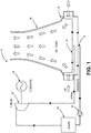
- FIG. 1 is a simplified system diagram of a power generating facility 10 with a condenser system 12 according to an embodiment of the invention.
- the condenser system 12 includes a supply system 14 and return system 16.
- the supply system 14 supplies waste steam from a power generating system and the return system 16 returns condensed water back to the power generating system via a pump 18 (for example).
- the power generating system generally includes a boiler 20 to generate steam which is utilized to drive a turbine 22 coupled to a generator 24.
- Waste heat, in the form of steam (for example) is supplied to the condenser system 12 and, as shown in FIG. 1 , this heat raises the temperature of air within a tower 26.
- the warmed air rises within the tower 26 which draws air from the base of the tower 26 through the condenser system 12. In this manner, a natural draft is established and maintained to remove heat from steam and/or condensate within the condenser system 12.
- FIG. 2 is a solid model projection of the cooling tower 26 suitable for use with the condenser system 12 of FIG. 1 .
- the condenser system 12 is disposed in an annular ring about the base of the tower 26.
- the condenser system 12 may include a crenulated annular ring. This crenulation may provide an increased surface area relative to a non-crenulated condenser system 12.
- the term 'crenulated' and derivations thereof refers to an outline that is irregular, wavy, serrated, and/or the like.
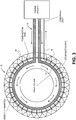
- FIG. 3 is a top view of the condenser system 12 of FIG. 1 .
- the supply system 14 and return system 16 are annular rings disposed within a plurality of panels or bundles 40 that are disposed in a crenulated pattern about the base of the tower 26 (shown in FIG. 2 ).
- these bundles 40 may include a panel of tubes with the tubes being separated by a space sufficient for a flow of air to pass therethrough.
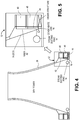
- FIG. 4 is a cross sectional view of the cooling tower 26 according to FIG. 2 .
- the condenser system 12 includes a plurality of bundles 40 stacked one upon the other. In this manner a length of tubing within the bundles 40 may be sized appropriately. That is, in some examples, it may be thermodynamically beneficial to have a relatively short length of tubing. In such an example, to increase the overall ability to remove heat, two or more additional bundles may be stacked up.
- the condenser system 12 may include a supply riser 42.
- the condenser system 12 may include a return piping 44.
- FIG. 5 is a more detailed cross sectional view of the condenser system 12 of FIG. 4 .
- the supply riser 42 is configured to provide steam to a top portion of the bundle 40.
- the return piping 44 is configured to provide an outlet for condensate from a lower portion of the bundle 40. It is an advantage of this and other embodiments that the lower bundle 40 provides support for the upper bundle 40. As such, little or no additional support structure is required which provides a commensurate reduction in costs.
- the tubes within the bundles 40 are disposed vertically within the bundles 40 and may include a relatively strong material having good thermal conductivity such as seamless refined copper or the like.
- FIG. 6 is a simplified top view of a displacement device 50 suitable for use with the condenser system 12 of FIG. 1 .
- the displacement device 50 is configured to facilitate expansion/contraction of the supply system 14. For example, ducting from the power generating facility 10 may expand as it is heated by the steam. This expansion, if not controlled for, may cause stress or damage to the condenser system 12.
- the displacement device 50 may be configured to allow one portion of the supply system 14 to move relative to another portion of the supply system 14. In a particular example, a sliding sleeve, bellows, or the like may provide this displacement capacity.
- radial displacement devices 52 may be disposed about the supply system 14 to facilitate expansion/contraction due to temperature fluctuations.
- FIG. 7 is a more detailed top view of the displacement device suitable for use with the condenser system of FIG. 6 .
- the supply system 14 may be configured as a pair of semi-circular ducts that taper in diameter towards a distal end of the supply system 14. In this manner, the pressure and/or velocity of steam within the supply system 14 may remain relatively constant throughout the supply system 14 ducting.
- FIG. 8 is a side view of the displacement device 50 suitable for use with the condenser system 12 of FIG. 1 .
- the supply riser 42 may include a displacement device 50 configured to facilitate expansion/contraction of the supply riser 42.
- the supply riser 42 may include a valve 54 configured to modulate flow of steam within the supply riser 42.
- the condenser system 12 includes a supply manifold 56 configured to distribute steam from the supply riser 42 across the bundle 40.
- the condenser system 12 includes a return manifold 58 configured to collect from the bundle 40.
- the bundle 40 includes a plurality of pipe assemblies 60.
- Each pipe assembly 60 may include one or more pipes generally arranged in a line. This plurality of pipe assemblies 60 may include a set of primary pipe assemblies 62 and one or more secondary pipe assemblies 64.
- the primary pipe assemblies 62 are configured to receive steam from the supply manifold 56, transfer heat from the steam to air flowing around the pipes, and convey condensate down to the return manifold 58.
- the secondary pipe assemblies 64 are included in any air-cooled condenser design. The function is to provide a means to capture and extract any non-condensable gases that may be contained in the steam.
- the secondary pipe assemblies 64 are not connected to the steam supply at the top, but are connected to the condensate line. Non-condensable gases are configured to flow into these bundles through the condensate line and be extracted using a vacuum system connect to the top of the secondary pipe assemblies 64.
- the bundle 40 is configured as a panel of vertical tubes.
- example will be made of the supply manifold, however, because the return manifold 58 is similar to the supply manifold 56, duplicative description of the return manifold will be omitted for the sake of brevity.
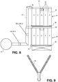
- FIG. 9 is a top view of a Y supply manifold 56 for the condenser system 12 of FIG. 1 .
- the supply manifold 56 is configured as a "Y" to distribute the steam from the supply riser 42 to the pipes within the pipe assemblies 40.
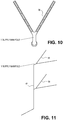
- FIG. 10 is a top view of the Y supply manifold 56 for the condenser system 12 of FIG. 1 .
- FIG. 11 is an isometric view of the Y supply manifold 56 for the condenser system 12 of FIG. 1 .
- the supply riser 42 includes a plurality of supply manifolds 56 with one supply manifold 56 for each respective bundle 40.
- FIG. 12 is a side view of the supply system 14 suitable for use with the condenser system 12 of FIG. 1 .
- FIG. 13 is an isometric view of the Y supply manifold 56 for the condenser system 12. As shown in FIG. 13 , steam flows up through the riser 42 into the respective supply manifolds 56 whereupon the flow of steam bifurcates to supply two bundles 40 with steam.
- FIG. 14 is a cross sectional view of the displacement device 50 suitable for use with a condenser system 12 according to another embodiment.
- the supply riser 42 may include a respective displacement device for each supply manifold 56.
- FIG. 15 is a simplified top view of a condenser system 12 according to yet another embodiment.
- the condenser system 12 may include a supply system 14 with a plurality of annular rings with one annular supply ring for each layer of bundles 40.
- the condenser system 12 may include a pair of annular rings or a pair of matched semi-circular ducts (for a total of four semi-circular ducts).
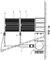
- FIG. 16 is an isometric view of a supply manifold for the condenser system of FIG. 15 .
- the flow of steam may be configured to rise within the supply riser 42 and annularly about the condenser system 12.
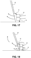
- FIGS. 17 and 18 are simplified cross sectional views of the condenser system 12 of FIG. 1 .
- the condenser system 12 optionally includes one or more louvers 70 that may be closed (as shown in FIG. 17 ) to facilitate increased airflow through the bundles 40 by reducing bypass airflow from entering the tower 26.
- the louvers 70 may be opened (as shown in FIG. 18 ) to increase the amount of bypass air entering the tower 26 and thereby reducing the airflow through the bundles 40.
Landscapes
- Engineering & Computer Science (AREA)
- Mechanical Engineering (AREA)
- General Engineering & Computer Science (AREA)
- Heat-Exchange Devices With Radiators And Conduit Assemblies (AREA)
- Apparatus Associated With Microorganisms And Enzymes (AREA)
Description
- The present invention generally relates to a system for condensing steam. More particularly, the present invention pertains to a natural draft condenser.
- Many types of industrial facilities, such as for example, steam power plants, require condensation of the steam as integral part of the closed steam cycle. Both wet and dry type cooling towers have been used for condensing purposes. As wet cooled systems consume a considerable amount of cooling water dry cooling systems have gained a growing market share because of their ability to save water resources. In particular, forced draught dry air-cooled condensers consisting of a multitude of fin tube heat exchangers have been known for many years. Contrary to wet cooling arrangements which are characterized by a secondary cooling water loop these systems are so-called "direct" dry systems where steam is directly condensed in the fin tube heat exchangers by air cooling. The fin tube heat exchangers are mounted with the tube center lines arranged in a position inclined to the vertical direction. The bundles are mounted to a support structure which enables cooling air to be conveyed through the fin tube heat exchangers by means of fans. Ambient air in contact with the fin tube heat exchangers condenses the steam inside the fin tubes, which then exits the heat exchanger as condensed sub-cooled liquid. Although being commercially successful over many years a disadvantage of direct dry air-cooled condensers is the power required to operate the fans, as well as fan noise which is undesirable in most situations. Currently 2 types of dry cooling are used, ACC fan assisted, and IDCT natural draft or fan assisted
- Another type of system is the so-called "indirect" dry cooling system. In such a system, a turbine exhaust condenser is provided, where turbine steam is condensed by means of cooling water. The cooling water is conveyed through a water duct by means of a pump to an air-cooled cooling tower which may be of wet or dry type. In the case of dry type the cooling tower consists of a multitude of air-cooled heat exchangers where the heat is rejected to the ambient air by convection. The cooling tower may be operated with fan assistance or in natural draught. The turbine exhaust condenser may for example be a surface or a jet condenser. Because of the presence of a secondary water loop, indirect dry cooling systems are not as thermally effective as direct dry systems.. Another disadvantage of natural draught indirect dry cooling systems, however, is the higher investment cost as compared to the forced draught direct air cooled condenser.
- Vacuum steam condensers are characterized by ingress of ambient air (inert gas or non-condensables). If not completely withdrawn from the heat exchangers this air will reduce the exchanger efficiency considerably because non-condensables will accumulate and create "air pockets" within the finned tubes. Consequently, effective heat exchange surface and condenser performance will be reduced. Therefore, vacuum condensers are provided with a secondary condenser arranged in reflux mode where the inert gases are extracted from the top exchanger headers of the secondary condenser bundles by special evacuation means. To safeguard that all inert gases are conveyed to these secondary condenser top headers the secondary condenser tube bundles must always be properly supplied by cooling air. Due to local fluctuations of ambient air caused by wind or other reasons natural draught cooled systems may in some instances not be able to maintain permanent secondary condenser cooling while some primary condenser sections are still cooled. This may not only lead to accumulation of inert gases and performance reduction, but also to increase of tube side corrosion as well as the danger of tube side freezing under frost conditions. As long as proper evacuation of the heat exchanger bundles is not guaranteed under all operating conditions the combination of dry condensation and natural draught cooling - although being discussed for some time - poses non-accountable risks to the operator of such equipment.
- Prior art condensing systems are disclosed by British patent with n°
908446 US patents 3,727,679 ,3,915,223 and3,942,588 , French patent application n°FR2360043 EP0794401 . More specifically,US patent 3,727,679 discloses a condensing tower comprising one level of self-standing condensing panels. But in such a system the circulation of air is aided by fans, which is onerous. - Accordingly, it is desirable to provide a system for condensing steam that is capable of overcoming the disadvantages described herein at least to some extent.
- The foregoing needs are met, to a great extent, by the present invention, wherein a system for condensing steam is provided.
- The present invention relates to a system for condensing steam. The system includes a supply manifold, a first pair of self-standing condensing panels, and a second pair of self-standing condensing panels. The supply manifold conveys steam from a steam supply. The first pair of self-standing condensing panels is configured to receive steam from the supply manifold. The supply manifold bifurcates with each bifurcation being configured to supply a respective condensing panel of the first pair of condensing panels. The second pair of self-standing condensing panels is disposed upon the first pair of self-standing condensing panels. The first pair of self-standing condensing panels is configured to support the second pair of self-standing condensing panels.
- The invention is not limited in its application to the details of construction and to the arrangements of the components set forth in the following description or illustrated in the drawings. The invention is capable of embodiments in addition to those described and of being practiced and carried out in various ways. Also, it is to be understood that the phraseology and terminology employed herein, as well as the abstract, are for the purpose of description and should not be regarded as limiting.
-
-
FIG. 1 is a simplified system diagram of a power generating facility with a system for condensing steam. -
FIG. 2 is a solid model projection of cooling tower suitable for use with the system for condensing steam ofFIG. 1 . -
FIG. 3 is a top view of the system for condensing steam ofFIG. 1 . -
FIG. 4 is a cross sectional view of the cooling tower ofFIG. 2 . -
FIG. 5 is a more detailed cross sectional view of the system for condensing steam ofFIG. 4 . -
FIG. 6 is a simplified top view of a displacement device suitable for use with the system for condensing steam ofFIG. 1 . -
FIG. 7 is a more detailed top view of the displacement device suitable for use with the system for condensing steam ofFIG. 6 . -
FIG. 8 is a side view of the displacement device suitable for use with the system for condensing steam ofFIG. 1 . -
FIG. 9 is a top view of a Y supply manifold for the system for condensing steam ofFIG. 1 . -
FIG. 10 is a top view of the Y supply manifold for the system for condensing steam ofFIG. 1 . -
FIG. 11 is an isometric view of the Y supply manifold for the system for condensing steam ofFIG. 1 . -
FIG. 12 is a side view of the supply system suitable for use with the system for condensing steam ofFIG. 1 . -
FIG. 13 is an isometric view of the Y supply manifold for the system for condensing steam ofFIG. 13 . -
FIG. 14 is a cross sectional view of the displacement device suitable for use with a system for condensing steam according to another embodiment. -
FIG. 15 is a simplified top view of a system for condensing steam according to another embodiment. -
FIG. 16 is an isometric view of a supply manifold for the system for condensing steam ofFIG. 15 . -
FIG. 17 is a simplified cross sectional view of the system for condensingsteam 12 ofFIG. 1 . -
FIG. 18 is a simplified cross sectional view of the system for condensingsteam 12 ofFIG. 1 . - The present invention provides, in various embodiments, a system for condensing steam suitable for use with a power generating facility. It is an advantage of one or more embodiments of the invention that supply ducting may be reduced relative to conventional condenser systems which results in a commensurate reduction in capital expenditures and upkeep. It is another advantage of one or more embodiments of the invention that return ducting may be reduced relative to conventional condenser systems which results in a commensurate reduction in capital expenditures and upkeep. It is yet another advantage of one or more embodiments of the invention that support structures associated with supporting condenser tubing, supply and return ducting may be reduced relative to conventional condenser systems which results in a commensurate reduction in capital expenditures and upkeep.
- Preferred embodiments of the invention will now be described with reference to the drawing figures, in which like reference numerals refer to like parts throughout.
FIG. 1 is a simplified system diagram of apower generating facility 10 with acondenser system 12 according to an embodiment of the invention. As shown inFIG. 1 , thecondenser system 12 includes asupply system 14 andreturn system 16. In a particular example, thesupply system 14 supplies waste steam from a power generating system and thereturn system 16 returns condensed water back to the power generating system via a pump 18 (for example). While the particulars of the power generating system are well known to those skilled in the art, the power generating system generally includes aboiler 20 to generate steam which is utilized to drive aturbine 22 coupled to agenerator 24. - Waste heat, in the form of steam (for example) is supplied to the
condenser system 12 and, as shown inFIG. 1 , this heat raises the temperature of air within atower 26. The warmed air rises within thetower 26 which draws air from the base of thetower 26 through thecondenser system 12. In this manner, a natural draft is established and maintained to remove heat from steam and/or condensate within thecondenser system 12. -
FIG. 2 is a solid model projection of thecooling tower 26 suitable for use with thecondenser system 12 ofFIG. 1 . As shown inFIG. 2 , thecondenser system 12 is disposed in an annular ring about the base of thetower 26. In a particular example, thecondenser system 12 may include a crenulated annular ring. This crenulation may provide an increased surface area relative to anon-crenulated condenser system 12. For the purpose of this disclosure, the term 'crenulated' and derivations thereof refers to an outline that is irregular, wavy, serrated, and/or the like. -
FIG. 3 is a top view of thecondenser system 12 ofFIG. 1 . As shown inFIG. 3 , thesupply system 14 andreturn system 16 are annular rings disposed within a plurality of panels or bundles 40 that are disposed in a crenulated pattern about the base of the tower 26 (shown inFIG. 2 ). As described herein, thesebundles 40 may include a panel of tubes with the tubes being separated by a space sufficient for a flow of air to pass therethrough. -
FIG. 4 is a cross sectional view of thecooling tower 26 according toFIG. 2 . As shown inFIG. 4 , thecondenser system 12 includes a plurality ofbundles 40 stacked one upon the other. In this manner a length of tubing within thebundles 40 may be sized appropriately. That is, in some examples, it may be thermodynamically beneficial to have a relatively short length of tubing. In such an example, to increase the overall ability to remove heat, two or more additional bundles may be stacked up. To supply steam to the stacked bundles 40, thecondenser system 12 may include asupply riser 42. To return condensate to thereturn system 16, thecondenser system 12 may include areturn piping 44. -
FIG. 5 is a more detailed cross sectional view of thecondenser system 12 ofFIG. 4 . As shown inFIG. 5 , thesupply riser 42 is configured to provide steam to a top portion of thebundle 40. Also shown inFIG. 5 , the return piping 44 is configured to provide an outlet for condensate from a lower portion of thebundle 40. It is an advantage of this and other embodiments that thelower bundle 40 provides support for theupper bundle 40. As such, little or no additional support structure is required which provides a commensurate reduction in costs. The tubes within thebundles 40 are disposed vertically within thebundles 40 and may include a relatively strong material having good thermal conductivity such as seamless refined copper or the like. -
FIG. 6 is a simplified top view of adisplacement device 50 suitable for use with thecondenser system 12 ofFIG. 1 . As shown inFIG. 6 , thedisplacement device 50 is configured to facilitate expansion/contraction of thesupply system 14. For example, ducting from thepower generating facility 10 may expand as it is heated by the steam. This expansion, if not controlled for, may cause stress or damage to thecondenser system 12. To control for this expansion or displacement, thedisplacement device 50 may be configured to allow one portion of thesupply system 14 to move relative to another portion of thesupply system 14. In a particular example, a sliding sleeve, bellows, or the like may provide this displacement capacity. - Also shown in
FIG. 6 ,radial displacement devices 52 may be disposed about thesupply system 14 to facilitate expansion/contraction due to temperature fluctuations. -
FIG. 7 is a more detailed top view of the displacement device suitable for use with the condenser system ofFIG. 6 . As shown inFIG. 7 , thesupply system 14 may be configured as a pair of semi-circular ducts that taper in diameter towards a distal end of thesupply system 14. In this manner, the pressure and/or velocity of steam within thesupply system 14 may remain relatively constant throughout thesupply system 14 ducting. -
FIG. 8 is a side view of thedisplacement device 50 suitable for use with thecondenser system 12 ofFIG. 1 . As shown inFIG. 8 , thesupply riser 42 may include adisplacement device 50 configured to facilitate expansion/contraction of thesupply riser 42. In addition, thesupply riser 42 may include avalve 54 configured to modulate flow of steam within thesupply riser 42. Also shown inFIG. 8 , thecondenser system 12 includes asupply manifold 56 configured to distribute steam from thesupply riser 42 across thebundle 40. Similarly, thecondenser system 12 includes areturn manifold 58 configured to collect from thebundle 40. In a particular example shown inFIG. 8 , thebundle 40 includes a plurality ofpipe assemblies 60. Eachpipe assembly 60 may include one or more pipes generally arranged in a line. This plurality ofpipe assemblies 60 may include a set ofprimary pipe assemblies 62 and one or moresecondary pipe assemblies 64. - The
primary pipe assemblies 62 are configured to receive steam from thesupply manifold 56, transfer heat from the steam to air flowing around the pipes, and convey condensate down to thereturn manifold 58. Thesecondary pipe assemblies 64 are included in any air-cooled condenser design. The function is to provide a means to capture and extract any non-condensable gases that may be contained in the steam. Thesecondary pipe assemblies 64 are not connected to the steam supply at the top, but are connected to the condensate line. Non-condensable gases are configured to flow into these bundles through the condensate line and be extracted using a vacuum system connect to the top of thesecondary pipe assemblies 64. - More generally, the
bundle 40 is configured as a panel of vertical tubes. In the following description, example will be made of the supply manifold, however, because thereturn manifold 58 is similar to thesupply manifold 56, duplicative description of the return manifold will be omitted for the sake of brevity. -
FIG. 9 is a top view of aY supply manifold 56 for thecondenser system 12 ofFIG. 1 . As shown inFIG. 9 , thesupply manifold 56 is configured as a "Y" to distribute the steam from thesupply riser 42 to the pipes within thepipe assemblies 40. -
FIG. 10 is a top view of theY supply manifold 56 for thecondenser system 12 ofFIG. 1 .FIG. 11 is an isometric view of theY supply manifold 56 for thecondenser system 12 ofFIG. 1 . As shown inFIG. 11 , thesupply riser 42 includes a plurality ofsupply manifolds 56 with onesupply manifold 56 for eachrespective bundle 40. -
FIG. 12 is a side view of thesupply system 14 suitable for use with thecondenser system 12 ofFIG. 1 .FIG. 13 is an isometric view of theY supply manifold 56 for thecondenser system 12. As shown inFIG. 13 , steam flows up through theriser 42 into therespective supply manifolds 56 whereupon the flow of steam bifurcates to supply twobundles 40 with steam. -
FIG. 14 is a cross sectional view of thedisplacement device 50 suitable for use with acondenser system 12 according to another embodiment. As shown inFIG 14 , thesupply riser 42 may include a respective displacement device for eachsupply manifold 56. -
FIG. 15 is a simplified top view of acondenser system 12 according to yet another embodiment. As shown inFIG. 15 , thecondenser system 12 may include asupply system 14 with a plurality of annular rings with one annular supply ring for each layer ofbundles 40. In a particular example, thecondenser system 12 may include a pair of annular rings or a pair of matched semi-circular ducts (for a total of four semi-circular ducts). -
FIG. 16 is an isometric view of a supply manifold for the condenser system ofFIG. 15 . As shown inFIG. 16 , the flow of steam may be configured to rise within thesupply riser 42 and annularly about thecondenser system 12. -
FIGS. 17 and 18 are simplified cross sectional views of thecondenser system 12 ofFIG. 1 . As shown inFIGS. 17 and 18 , thecondenser system 12 optionally includes one ormore louvers 70 that may be closed (as shown inFIG. 17 ) to facilitate increased airflow through thebundles 40 by reducing bypass airflow from entering thetower 26. Thelouvers 70 may be opened (as shown inFIG. 18 ) to increase the amount of bypass air entering thetower 26 and thereby reducing the airflow through thebundles 40. - The many features and advantages of the invention are apparent from the detailed specification, and thus, it is intended by the appended claims to cover all such features and advantages of the invention which fall within the true spirit and scope of the invention. Further, since numerous modifications and variations will readily occur to those skilled in the art, it is not desired to limit the invention to the exact construction and operation illustrated and described, and accordingly, all suitable modifications and equivalents may be resorted to, falling within the scope of the invention.
Claims (8)
- A system (12) for condensing steam, the system comprising:- a first horizontal supply manifold (56) and a second horizontal supply manifold (56) to convey steam from a steam supply (14),- a first horizontal return manifold (58) and a second horizontal return manifold (58) to return condensate to a return pipe (16)- a first pair of self-standing condensing panels configured to stand without a support structure, to receive steam from the first supply manifold (56) wherein the first supply manifold (56) bifurcates with each bifurcation being configured to supply a respective condensing panel of the first pair of condensing panels,- a second pair of self-standing condensing panels configured to stand without a support structure to receive steam from the second supply manifold (56) wherein the second supply manifold (56) bifurcates with each bifurcation being configured to supply a respective condensing panel of the second pair of condensing panels, wherein the second pair of self-standing condensing panels is disposed upon the first pair of self-standing condensing panels,characterized in that:the first pair of self-standing condensing panels supports the second pair of self-standing condensing panels; each condensing panel is configured as a bundle (40) of vertical tubes; each panel of the first pair of self-standing panels extends between a bifurcation of the first supply manifold (56) and a bifurcation of the first return manifold (58);and each panel of the second pair of self-standing panel extends between a bifurcation of the second supply manifold (56) and a bifurcation of the second return manifold (58).
- The system according to claim 1, further comprising:a flow of cooling fluid configured to flow through the first pair of self-standing condensing panels and the second pair of self-standing condensing panels.
- The system according to claim 2, further comprising:a natural draft tower (26) configured to supply the flow of cooling fluid.
- The system according to claim 3, further comprising:a crenulated ring disposed about a base of the natural draft tower, the crenulated ring including a plurality of the first pair of self-standing condensing panels and a plurality of the second pair of self-standing condensing panels.
- The system according to claim 2, further comprising:a set of louvers (70) to modulate a bypass flow, wherein the flow of cooling fluid flowing through the first pair of self-standing condensing panels and the second pair of self-standing condensing panels is inversely affected by the bypass flow.
- The system according to claim 1, further comprising:a boiler (20) configured to generate the steam supply; anda pump (18) to urge a condensate to flow from the first pair of self-standing condensing panels and the second pair of self-standing condensing panels to the boiler.
- The system according to claim 6, further comprising:a turbine (22) configured to generate power in response to receiving the steam from the boiler.
- The system according to claim 1, further comprising:a bellows disposed in the supply manifold between the steam supply and the first and second pair of self-standing condensing panels.
Applications Claiming Priority (2)
| Application Number | Priority Date | Filing Date | Title |
|---|---|---|---|
| US40966610P | 2010-11-03 | 2010-11-03 | |
| PCT/US2011/058762 WO2012061369A1 (en) | 2010-11-03 | 2011-11-01 | Natural draft condenser |
Publications (3)
| Publication Number | Publication Date |
|---|---|
| EP2635865A1 EP2635865A1 (en) | 2013-09-11 |
| EP2635865A4 EP2635865A4 (en) | 2014-11-05 |
| EP2635865B1 true EP2635865B1 (en) | 2017-06-28 |
Family
ID=45995363
Family Applications (1)
| Application Number | Title | Priority Date | Filing Date |
|---|---|---|---|
| EP11838668.9A Active EP2635865B1 (en) | 2010-11-03 | 2011-11-01 | System for condensing steam |
Country Status (6)
| Country | Link |
|---|---|
| US (1) | US8833082B2 (en) |
| EP (1) | EP2635865B1 (en) |
| CN (1) | CN103261826B (en) |
| AU (1) | AU2011323516B2 (en) |
| ES (1) | ES2641067T3 (en) |
| WO (1) | WO2012061369A1 (en) |
Families Citing this family (4)
| Publication number | Priority date | Publication date | Assignee | Title |
|---|---|---|---|---|
| FR3033036B1 (en) * | 2015-02-19 | 2017-03-17 | Electricite De France | METHOD FOR DETECTING DEFICIENCIES OF A FRESHWATER OF A THERMAL INSTALLATION IN OPERATION |
| BE1024229B1 (en) * | 2017-10-31 | 2019-05-27 | Hamon Thermal Europe S.A. | Cooling unit, installation and process |
| CN109780882B (en) * | 2019-03-29 | 2024-02-06 | 中国电力工程顾问集团西北电力设计院有限公司 | Overlapped type vertical plate condenser and hertz dry cooling system |
| SE547323C2 (en) * | 2023-02-10 | 2025-07-01 | Climeon Ab | Thermodynamic system comprising a pump assembly |
Family Cites Families (18)
| Publication number | Priority date | Publication date | Assignee | Title |
|---|---|---|---|---|
| DE1153779B (en) * | 1958-12-15 | 1963-09-05 | Gea Luftkuehler Happel Gmbh | With a forced cooling air flow charged surface condenser for large steam power plants |
| US3406747A (en) * | 1966-01-18 | 1968-10-22 | American Schack Company Inc | Heat exchanger having concentric supply and exhaust conduits |
| US3498590A (en) * | 1968-06-13 | 1970-03-03 | Fluor Prod Co Inc | Spiral draft water cooling tower |
| US3915223A (en) * | 1970-09-22 | 1975-10-28 | Siemens Ag | Steam power installation having a cooling tower-air condensation apparatus |
| DE2100018A1 (en) * | 1971-01-02 | 1972-07-13 | Gea Luftkuehler Happel Gmbh | Forced ventilated cooling or condensing system |
| DE2108615B2 (en) * | 1971-02-24 | 1978-03-02 | Kraftwerk Union Ag, 4330 Muelheim | Air-cooled condensation device |
| BE790512A (en) * | 1971-10-25 | 1973-02-15 | Tyeploelektroprojekt | CONDENSATION SYSTEM FOR PLANTS EQUIPPED WITH STEAM TURBINES |
| DE2242058B2 (en) * | 1972-08-26 | 1980-06-19 | Balcke-Duerr Ag, 4030 Ratingen | Cooling tower with a tubular, vertical jacket |
| US3880964A (en) * | 1972-09-05 | 1975-04-29 | Marley Co | Hot water supply and distribution structure for cooling towers |
| US3903212A (en) * | 1973-07-10 | 1975-09-02 | Cottrell Res Inc | Fan-assisted cooling tower and method of operation |
| DE2405999C3 (en) * | 1974-02-08 | 1981-06-04 | GEA Luftkühlergesellschaft Happel GmbH & Co KG, 4630 Bochum | Natural draft dry cooling tower |
| US3942588A (en) * | 1974-11-04 | 1976-03-09 | The Lummus Company | Cooling tower |
| FR2360043A1 (en) * | 1976-07-30 | 1978-02-24 | Chausson Usines Sa | Cooling tower with closed cooling circuit - has open timber framework supporting tower shell with fluid circulated in closed pipes and has automatically controlled, hinged damper flaps |
| DE2636807C3 (en) * | 1976-08-16 | 1979-05-10 | Kraftwerk Union Ag, 4330 Muelheim | Cooling tower with forced ventilation and natural draft |
| US4397793A (en) * | 1978-06-08 | 1983-08-09 | Stillman Gerald I | Confined vortex cooling tower |
| US4243095A (en) * | 1979-02-15 | 1981-01-06 | The Lummus Company | Cooling tower |
| US5156706A (en) * | 1982-09-07 | 1992-10-20 | Sephton Hugo H | Evaporation of liquids with dispersant added |
| EP0794401A3 (en) * | 1996-03-06 | 1998-09-23 | Hudson Products Corporation | Steam condensing apparatus |
-
2011
- 2011-11-01 ES ES11838668.9T patent/ES2641067T3/en active Active
- 2011-11-01 US US13/286,538 patent/US8833082B2/en active Active
- 2011-11-01 CN CN201180061238.XA patent/CN103261826B/en active Active
- 2011-11-01 WO PCT/US2011/058762 patent/WO2012061369A1/en not_active Ceased
- 2011-11-01 AU AU2011323516A patent/AU2011323516B2/en not_active Ceased
- 2011-11-01 EP EP11838668.9A patent/EP2635865B1/en active Active
Non-Patent Citations (1)
| Title |
|---|
| None * |
Also Published As
| Publication number | Publication date |
|---|---|
| CN103261826A (en) | 2013-08-21 |
| US20120103570A1 (en) | 2012-05-03 |
| EP2635865A4 (en) | 2014-11-05 |
| AU2011323516B2 (en) | 2015-10-15 |
| EP2635865A1 (en) | 2013-09-11 |
| ES2641067T3 (en) | 2017-11-07 |
| WO2012061369A1 (en) | 2012-05-10 |
| CN103261826B (en) | 2016-01-20 |
| US8833082B2 (en) | 2014-09-16 |
| AU2011323516A1 (en) | 2013-05-23 |
Similar Documents
| Publication | Publication Date | Title |
|---|---|---|
| EP2429690B1 (en) | Natural draft air cooled steam condenser | |
| RU2483265C2 (en) | General-purpose recuperator assembly for waste gases of gas turbine | |
| EP2667133B1 (en) | Method for air cooled condenser apparatus. | |
| EP2369283B1 (en) | A cooling tower for cooling an industrial fluid and a method for colling an industrial fluid using the latter | |
| US8833082B2 (en) | Natural draft condenser | |
| EP2369282B1 (en) | An apparatus and a method for a natural draft air cooled condenser cooling tower | |
| CN104359223B (en) | System and method for using steam turbine exhaust steam as heat medium of power plant boiler heater | |
| CN107421348A (en) | The gravity-flow ventilation direct air cooling system that a kind of fin is in tilted layout | |
| RU116983U1 (en) | MULTI-WAY AIR COOLED VAPOR TURBINE CONDENSER WITH ABC GI VARIABLE SPEED | |
| CN111504077A (en) | Natural draft direct air cooling system | |
| JP2025528559A (en) | Air condensers for organic Rankine cycle plants. | |
| CN210543450U (en) | A suction type direct steam cooling system | |
| RU92160U1 (en) | SECTION SECTION TYPE ABC GI AIR COOLING UNIT | |
| CN207035879U (en) | A kind of plate type heat exchanger with shell and tube attemperator | |
| CN216558464U (en) | PVC polymerization drying radiator | |
| CN204313486U (en) | System using exhaust steam in steam turbine as steam air heater of utility boiler thermal medium | |
| CN219265019U (en) | Mechanical power-assisted natural ventilation direct air cooling system | |
| RU92161U1 (en) | SECTION SECTION TYPE ABC GI AIR COOLING UNIT | |
| RU102251U1 (en) | HEAT EXCHANGE SECTION | |
| JP2011094908A (en) | Air-cooled condenser | |
| JP2011122740A (en) | Air-cooled condenser |
Legal Events
| Date | Code | Title | Description |
|---|---|---|---|
| PUAI | Public reference made under article 153(3) epc to a published international application that has entered the european phase |
Free format text: ORIGINAL CODE: 0009012 |
|
| 17P | Request for examination filed |
Effective date: 20130531 |
|
| AK | Designated contracting states |
Kind code of ref document: A1 Designated state(s): AL AT BE BG CH CY CZ DE DK EE ES FI FR GB GR HR HU IE IS IT LI LT LU LV MC MK MT NL NO PL PT RO RS SE SI SK SM TR |
|
| DAX | Request for extension of the european patent (deleted) | ||
| A4 | Supplementary search report drawn up and despatched |
Effective date: 20141007 |
|
| RIC1 | Information provided on ipc code assigned before grant |
Ipc: F28B 1/06 20060101AFI20140930BHEP |
|
| 17Q | First examination report despatched |
Effective date: 20151218 |
|
| RAP1 | Party data changed (applicant data changed or rights of an application transferred) |
Owner name: SPX DRY COOLING USA LLC |
|
| GRAP | Despatch of communication of intention to grant a patent |
Free format text: ORIGINAL CODE: EPIDOSNIGR1 |
|
| INTG | Intention to grant announced |
Effective date: 20170130 |
|
| GRAS | Grant fee paid |
Free format text: ORIGINAL CODE: EPIDOSNIGR3 |
|
| GRAA | (expected) grant |
Free format text: ORIGINAL CODE: 0009210 |
|
| AK | Designated contracting states |
Kind code of ref document: B1 Designated state(s): AL AT BE BG CH CY CZ DE DK EE ES FI FR GB GR HR HU IE IS IT LI LT LU LV MC MK MT NL NO PL PT RO RS SE SI SK SM TR |
|
| REG | Reference to a national code |
Ref country code: GB Ref legal event code: FG4D |
|
| REG | Reference to a national code |
Ref country code: CH Ref legal event code: EP |
|
| REG | Reference to a national code |
Ref country code: AT Ref legal event code: REF Ref document number: 905257 Country of ref document: AT Kind code of ref document: T Effective date: 20170715 |
|
| REG | Reference to a national code |
Ref country code: IE Ref legal event code: FG4D |
|
| REG | Reference to a national code |
Ref country code: DE Ref legal event code: R096 Ref document number: 602011039198 Country of ref document: DE |
|
| PG25 | Lapsed in a contracting state [announced via postgrant information from national office to epo] |
Ref country code: FI Free format text: LAPSE BECAUSE OF FAILURE TO SUBMIT A TRANSLATION OF THE DESCRIPTION OR TO PAY THE FEE WITHIN THE PRESCRIBED TIME-LIMIT Effective date: 20170628 Ref country code: NO Free format text: LAPSE BECAUSE OF FAILURE TO SUBMIT A TRANSLATION OF THE DESCRIPTION OR TO PAY THE FEE WITHIN THE PRESCRIBED TIME-LIMIT Effective date: 20170928 Ref country code: HR Free format text: LAPSE BECAUSE OF FAILURE TO SUBMIT A TRANSLATION OF THE DESCRIPTION OR TO PAY THE FEE WITHIN THE PRESCRIBED TIME-LIMIT Effective date: 20170628 Ref country code: GR Free format text: LAPSE BECAUSE OF FAILURE TO SUBMIT A TRANSLATION OF THE DESCRIPTION OR TO PAY THE FEE WITHIN THE PRESCRIBED TIME-LIMIT Effective date: 20170929 Ref country code: LT Free format text: LAPSE BECAUSE OF FAILURE TO SUBMIT A TRANSLATION OF THE DESCRIPTION OR TO PAY THE FEE WITHIN THE PRESCRIBED TIME-LIMIT Effective date: 20170628 |
|
| REG | Reference to a national code |
Ref country code: NL Ref legal event code: MP Effective date: 20170628 |
|
| REG | Reference to a national code |
Ref country code: ES Ref legal event code: FG2A Ref document number: 2641067 Country of ref document: ES Kind code of ref document: T3 Effective date: 20171107 |
|
| REG | Reference to a national code |
Ref country code: LT Ref legal event code: MG4D |
|
| REG | Reference to a national code |
Ref country code: FR Ref legal event code: PLFP Year of fee payment: 7 |
|
| REG | Reference to a national code |
Ref country code: AT Ref legal event code: MK05 Ref document number: 905257 Country of ref document: AT Kind code of ref document: T Effective date: 20170628 |
|
| PG25 | Lapsed in a contracting state [announced via postgrant information from national office to epo] |
Ref country code: NL Free format text: LAPSE BECAUSE OF FAILURE TO SUBMIT A TRANSLATION OF THE DESCRIPTION OR TO PAY THE FEE WITHIN THE PRESCRIBED TIME-LIMIT Effective date: 20170628 Ref country code: LV Free format text: LAPSE BECAUSE OF FAILURE TO SUBMIT A TRANSLATION OF THE DESCRIPTION OR TO PAY THE FEE WITHIN THE PRESCRIBED TIME-LIMIT Effective date: 20170628 Ref country code: BG Free format text: LAPSE BECAUSE OF FAILURE TO SUBMIT A TRANSLATION OF THE DESCRIPTION OR TO PAY THE FEE WITHIN THE PRESCRIBED TIME-LIMIT Effective date: 20170928 Ref country code: RS Free format text: LAPSE BECAUSE OF FAILURE TO SUBMIT A TRANSLATION OF THE DESCRIPTION OR TO PAY THE FEE WITHIN THE PRESCRIBED TIME-LIMIT Effective date: 20170628 Ref country code: SE Free format text: LAPSE BECAUSE OF FAILURE TO SUBMIT A TRANSLATION OF THE DESCRIPTION OR TO PAY THE FEE WITHIN THE PRESCRIBED TIME-LIMIT Effective date: 20170628 |
|
| PG25 | Lapsed in a contracting state [announced via postgrant information from national office to epo] |
Ref country code: RO Free format text: LAPSE BECAUSE OF FAILURE TO SUBMIT A TRANSLATION OF THE DESCRIPTION OR TO PAY THE FEE WITHIN THE PRESCRIBED TIME-LIMIT Effective date: 20170628 Ref country code: SK Free format text: LAPSE BECAUSE OF FAILURE TO SUBMIT A TRANSLATION OF THE DESCRIPTION OR TO PAY THE FEE WITHIN THE PRESCRIBED TIME-LIMIT Effective date: 20170628 Ref country code: EE Free format text: LAPSE BECAUSE OF FAILURE TO SUBMIT A TRANSLATION OF THE DESCRIPTION OR TO PAY THE FEE WITHIN THE PRESCRIBED TIME-LIMIT Effective date: 20170628 Ref country code: AT Free format text: LAPSE BECAUSE OF FAILURE TO SUBMIT A TRANSLATION OF THE DESCRIPTION OR TO PAY THE FEE WITHIN THE PRESCRIBED TIME-LIMIT Effective date: 20170628 Ref country code: CZ Free format text: LAPSE BECAUSE OF FAILURE TO SUBMIT A TRANSLATION OF THE DESCRIPTION OR TO PAY THE FEE WITHIN THE PRESCRIBED TIME-LIMIT Effective date: 20170628 |
|
| PG25 | Lapsed in a contracting state [announced via postgrant information from national office to epo] |
Ref country code: IS Free format text: LAPSE BECAUSE OF FAILURE TO SUBMIT A TRANSLATION OF THE DESCRIPTION OR TO PAY THE FEE WITHIN THE PRESCRIBED TIME-LIMIT Effective date: 20171028 Ref country code: SM Free format text: LAPSE BECAUSE OF FAILURE TO SUBMIT A TRANSLATION OF THE DESCRIPTION OR TO PAY THE FEE WITHIN THE PRESCRIBED TIME-LIMIT Effective date: 20170628 Ref country code: PL Free format text: LAPSE BECAUSE OF FAILURE TO SUBMIT A TRANSLATION OF THE DESCRIPTION OR TO PAY THE FEE WITHIN THE PRESCRIBED TIME-LIMIT Effective date: 20170628 |
|
| REG | Reference to a national code |
Ref country code: DE Ref legal event code: R097 Ref document number: 602011039198 Country of ref document: DE |
|
| PG25 | Lapsed in a contracting state [announced via postgrant information from national office to epo] |
Ref country code: DK Free format text: LAPSE BECAUSE OF FAILURE TO SUBMIT A TRANSLATION OF THE DESCRIPTION OR TO PAY THE FEE WITHIN THE PRESCRIBED TIME-LIMIT Effective date: 20170628 |
|
| PLBE | No opposition filed within time limit |
Free format text: ORIGINAL CODE: 0009261 |
|
| STAA | Information on the status of an ep patent application or granted ep patent |
Free format text: STATUS: NO OPPOSITION FILED WITHIN TIME LIMIT |
|
| 26N | No opposition filed |
Effective date: 20180329 |
|
| PG25 | Lapsed in a contracting state [announced via postgrant information from national office to epo] |
Ref country code: MC Free format text: LAPSE BECAUSE OF FAILURE TO SUBMIT A TRANSLATION OF THE DESCRIPTION OR TO PAY THE FEE WITHIN THE PRESCRIBED TIME-LIMIT Effective date: 20170628 |
|
| PG25 | Lapsed in a contracting state [announced via postgrant information from national office to epo] |
Ref country code: LI Free format text: LAPSE BECAUSE OF NON-PAYMENT OF DUE FEES Effective date: 20171130 Ref country code: CH Free format text: LAPSE BECAUSE OF NON-PAYMENT OF DUE FEES Effective date: 20171130 |
|
| PG25 | Lapsed in a contracting state [announced via postgrant information from national office to epo] |
Ref country code: LU Free format text: LAPSE BECAUSE OF NON-PAYMENT OF DUE FEES Effective date: 20171101 Ref country code: SI Free format text: LAPSE BECAUSE OF FAILURE TO SUBMIT A TRANSLATION OF THE DESCRIPTION OR TO PAY THE FEE WITHIN THE PRESCRIBED TIME-LIMIT Effective date: 20170628 |
|
| REG | Reference to a national code |
Ref country code: IE Ref legal event code: MM4A |
|
| PG25 | Lapsed in a contracting state [announced via postgrant information from national office to epo] |
Ref country code: MT Free format text: LAPSE BECAUSE OF NON-PAYMENT OF DUE FEES Effective date: 20171101 |
|
| PG25 | Lapsed in a contracting state [announced via postgrant information from national office to epo] |
Ref country code: IE Free format text: LAPSE BECAUSE OF NON-PAYMENT OF DUE FEES Effective date: 20171101 |
|
| PG25 | Lapsed in a contracting state [announced via postgrant information from national office to epo] |
Ref country code: HU Free format text: LAPSE BECAUSE OF FAILURE TO SUBMIT A TRANSLATION OF THE DESCRIPTION OR TO PAY THE FEE WITHIN THE PRESCRIBED TIME-LIMIT; INVALID AB INITIO Effective date: 20111101 |
|
| PG25 | Lapsed in a contracting state [announced via postgrant information from national office to epo] |
Ref country code: CY Free format text: LAPSE BECAUSE OF NON-PAYMENT OF DUE FEES Effective date: 20170628 |
|
| REG | Reference to a national code |
Ref country code: DE Ref legal event code: R081 Ref document number: 602011039198 Country of ref document: DE Owner name: SPG DRY COOLING USA LLC, OVERLAND PARK, US Free format text: FORMER OWNER: SPX DRY COOLING USA LLC, OVERLAND PARK, KAN., US |
|
| REG | Reference to a national code |
Ref country code: ES Ref legal event code: PC2A Owner name: SPG DRY COOLING USA LLC Effective date: 20191113 |
|
| PG25 | Lapsed in a contracting state [announced via postgrant information from national office to epo] |
Ref country code: MK Free format text: LAPSE BECAUSE OF FAILURE TO SUBMIT A TRANSLATION OF THE DESCRIPTION OR TO PAY THE FEE WITHIN THE PRESCRIBED TIME-LIMIT Effective date: 20170628 |
|
| REG | Reference to a national code |
Ref country code: BE Ref legal event code: HC Owner name: SPG DRY COOLING USA LLC; US Free format text: DETAILS ASSIGNMENT: CHANGE OF OWNER(S), CHANGEMENT DE NOM DU PROPRIETAIRE; FORMER OWNER NAME: SPX DRY COOLING USA LLC Effective date: 20191220 |
|
| PG25 | Lapsed in a contracting state [announced via postgrant information from national office to epo] |
Ref country code: TR Free format text: LAPSE BECAUSE OF FAILURE TO SUBMIT A TRANSLATION OF THE DESCRIPTION OR TO PAY THE FEE WITHIN THE PRESCRIBED TIME-LIMIT Effective date: 20170628 |
|
| PG25 | Lapsed in a contracting state [announced via postgrant information from national office to epo] |
Ref country code: PT Free format text: LAPSE BECAUSE OF FAILURE TO SUBMIT A TRANSLATION OF THE DESCRIPTION OR TO PAY THE FEE WITHIN THE PRESCRIBED TIME-LIMIT Effective date: 20170628 |
|
| PG25 | Lapsed in a contracting state [announced via postgrant information from national office to epo] |
Ref country code: AL Free format text: LAPSE BECAUSE OF FAILURE TO SUBMIT A TRANSLATION OF THE DESCRIPTION OR TO PAY THE FEE WITHIN THE PRESCRIBED TIME-LIMIT Effective date: 20170628 |
|
| P01 | Opt-out of the competence of the unified patent court (upc) registered |
Effective date: 20230530 |
|
| PGFP | Annual fee paid to national office [announced via postgrant information from national office to epo] |
Ref country code: DE Payment date: 20251119 Year of fee payment: 15 |
|
| PGFP | Annual fee paid to national office [announced via postgrant information from national office to epo] |
Ref country code: GB Payment date: 20251121 Year of fee payment: 15 |
|
| PGFP | Annual fee paid to national office [announced via postgrant information from national office to epo] |
Ref country code: IT Payment date: 20251125 Year of fee payment: 15 |
|
| PGFP | Annual fee paid to national office [announced via postgrant information from national office to epo] |
Ref country code: FR Payment date: 20251125 Year of fee payment: 15 |
|
| PGFP | Annual fee paid to national office [announced via postgrant information from national office to epo] |
Ref country code: BE Payment date: 20251119 Year of fee payment: 15 |
|
| PGFP | Annual fee paid to national office [announced via postgrant information from national office to epo] |
Ref country code: ES Payment date: 20251229 Year of fee payment: 15 |