EP0794401A2 - Steam condensing apparatus - Google Patents
Steam condensing apparatus Download PDFInfo
- Publication number
- EP0794401A2 EP0794401A2 EP97300956A EP97300956A EP0794401A2 EP 0794401 A2 EP0794401 A2 EP 0794401A2 EP 97300956 A EP97300956 A EP 97300956A EP 97300956 A EP97300956 A EP 97300956A EP 0794401 A2 EP0794401 A2 EP 0794401A2
- Authority
- EP
- European Patent Office
- Prior art keywords
- steam
- condenser
- heat pipes
- header
- condensing apparatus
- Prior art date
- Legal status (The legal status is an assumption and is not a legal conclusion. Google has not performed a legal analysis and makes no representation as to the accuracy of the status listed.)
- Withdrawn
Links
Images


Classifications
-
- F—MECHANICAL ENGINEERING; LIGHTING; HEATING; WEAPONS; BLASTING
- F28—HEAT EXCHANGE IN GENERAL
- F28B—STEAM OR VAPOUR CONDENSERS
- F28B1/00—Condensers in which the steam or vapour is separate from the cooling medium by walls, e.g. surface condenser
-
- F—MECHANICAL ENGINEERING; LIGHTING; HEATING; WEAPONS; BLASTING
- F28—HEAT EXCHANGE IN GENERAL
- F28F—DETAILS OF HEAT-EXCHANGE AND HEAT-TRANSFER APPARATUS, OF GENERAL APPLICATION
- F28F19/00—Preventing the formation of deposits or corrosion, e.g. by using filters or scrapers
- F28F19/02—Preventing the formation of deposits or corrosion, e.g. by using filters or scrapers by using coatings, e.g. vitreous or enamel coatings
- F28F19/04—Preventing the formation of deposits or corrosion, e.g. by using filters or scrapers by using coatings, e.g. vitreous or enamel coatings of rubber; of plastics material; of varnish
-
- F—MECHANICAL ENGINEERING; LIGHTING; HEATING; WEAPONS; BLASTING
- F28—HEAT EXCHANGE IN GENERAL
- F28B—STEAM OR VAPOUR CONDENSERS
- F28B1/00—Condensers in which the steam or vapour is separate from the cooling medium by walls, e.g. surface condenser
- F28B1/06—Condensers in which the steam or vapour is separate from the cooling medium by walls, e.g. surface condenser using air or other gas as the cooling medium
-
- F—MECHANICAL ENGINEERING; LIGHTING; HEATING; WEAPONS; BLASTING
- F28—HEAT EXCHANGE IN GENERAL
- F28D—HEAT-EXCHANGE APPARATUS, NOT PROVIDED FOR IN ANOTHER SUBCLASS, IN WHICH THE HEAT-EXCHANGE MEDIA DO NOT COME INTO DIRECT CONTACT
- F28D15/00—Heat-exchange apparatus with the intermediate heat-transfer medium in closed tubes passing into or through the conduit walls ; Heat-exchange apparatus employing intermediate heat-transfer medium or bodies
- F28D15/02—Heat-exchange apparatus with the intermediate heat-transfer medium in closed tubes passing into or through the conduit walls ; Heat-exchange apparatus employing intermediate heat-transfer medium or bodies in which the medium condenses and evaporates, e.g. heat pipes
-
- F—MECHANICAL ENGINEERING; LIGHTING; HEATING; WEAPONS; BLASTING
- F28—HEAT EXCHANGE IN GENERAL
- F28B—STEAM OR VAPOUR CONDENSERS
- F28B1/00—Condensers in which the steam or vapour is separate from the cooling medium by walls, e.g. surface condenser
- F28B1/06—Condensers in which the steam or vapour is separate from the cooling medium by walls, e.g. surface condenser using air or other gas as the cooling medium
- F28B2001/065—Condensers in which the steam or vapour is separate from the cooling medium by walls, e.g. surface condenser using air or other gas as the cooling medium with secondary condenser, e.g. reflux condenser or dephlegmator
Definitions
- the invention relates to steam condensing apparatus, and in particular to such apparatus that combines the use of steam condensing technology with heat pipe technology.
- Air-cooled steam condensers used in the steam power-generation cycle are typically arranged in an A-frame construction with a fan at the base and inclined condenser tube bundles on each side. Air flows through the fan and across several sections of the steam condenser. The steam inlet is at the top of each bundle and the vapour and condensate flow concurrently downwards.
- the differences in tube row exit pressures are resolved by steam and noncondensable gases in the rear header entering the ends of the tube rows that have a lower pressure. Since the lower tube rows have lower exit pressures, they have steam entering both ends and, over time, noncondensable gases collect in the tubes. These pockets of noncondensable gases block local steam flow, allowing condensate to freeze during cold weather, which can result in tube rupture. Noncondensable gases are normally vented from the rear header with vacuum pumps or air ejectors. To overcome this problem, the classical solution has been to design for excess steam flow through each tube row. The excess steam prevents the accumulation of noncondensable gases and maintains condensate temperatures above freezing.
- This excess steam typically twenty to thirty-three percent of the total steam flow, is condensed in a secondary or vent condenser.
- the typical vent condenser is a dephlegmator (reflux condenser) which has steam flow up an inclined tube, condensation on the tube walls, and drainage of the condensate downwardly.
- the noncondensable gases flow upwards out of the tube and are removed by vacuum pumps or air ejectors.
- Steam condenser freezing problems have also been overcome in the past through the use of heat pipes. Heat pipes were used to condense steam. The steam was passed over the evaporator side of the heat pipes and condensed while ambient air was forced over the condenser side of the heat pipes. The condensate was collected at the bottom of the steam duct and returned to the boiler for reuse.
- Embodiments of the invention provide an air-cooled steam condenser that also uses heat pipe technology so as to be freeze proof under any ambient conditions, and offering a simple approach to the management of noncondensable gases.
- Steam flows through the main condenser with concurrent steam and condensate flow downwardly.
- the heat transfer surface area and fan air flow are designed such that, over the range of operating conditions, all of the steam does not completely condense and vapour continuously exits each tube row. This continuous flow of steam vapour purges these rows of noncondensable gases.
- the excess steam flows into the lower header to a secondary condenser section that utilizes heat pipes. In the secondary condenser section, the excess steam condenses on the evaporator side external surface of the heat pipes.
- the noncondensable gases that remain in the lower header are vented with an air removal system similar to that of conventional condensers. Condensate in the lower header drains to a condensate tank for reuse in the power generation cycle.
- air-cooled steam condensers are typically arranged in an A-frame construction with a fan 10 at the base and inclined condenser tube bundles 12 on each side. Air flows through the fan 10 across several sections of the steam condenser. Steam from a steam turbine 14 is directed to an upper steam header 16 which provides a steam inlet at the top of each bundle 12. The vapour and condensate flow concurrently downwards in the bundle 12 to a lower or rear header 18. An air ejector or vacuum pump 20 is used to vent noncondensable gases from the rear header 18. The condensate is collected in a tank 22 and directed to condensate pumps (not shown) for reuse.
- FIG. 2 illustrates a previously-proposed solution to prevent freezing of condensate.
- the condenser tube bundle 12 is designed to cause excess steam flow through each tube row.
- the excess steam prevents the accumulation of noncondensable gases and maintains condensate temperatures above freezing.
- This excess steam is condensed in a secondary or vent condenser 24.
- the typical vent condenser 24 is a dephlegmator (reflux condenser) which has steam flow up an inclined tube, condensation on the tube walls, and drainage of the condensate downwardly.
- the noncondensable gases flow upwards out of the tube and are removed by vacuum pumps or air ejectors.
- FIG. 3 illustrates another previously-proposed solution to prevent freezing of condensate.
- Heat pipes 26 are set up in a Y configuration.
- the evaporator side of the heat pipes is enclosed in a steam header 28.
- the steam is condensed as it passes across the evaporator side of the heat pipes 26.
- the condensate is collected at the bottom of the header 28 and returned to the boiler for reuse.
- the fan 10 causes induced air flow across the condenser sides of the heat pipes to cause cooling and recondensation of the working fluid contained in the heat pipes.
- a steam condensing apparatus 30 generally comprises a main condenser 32, a lower header 34, and a secondary condenser 36.
- the main condenser 32 is formed from an upper steam header 38 and one or more tube bundles 40.
- the upper steam header 38 receives steam from a steam turbine 42 via a line 44 and then directs the steam into the tube bundles 40.
- Each tube bundle 40 is similar to tube bundles generally known and used in the industry in that several rows of tubes, usually four, are provided for receiving and condensing steam.
- the main difference in the tube bundles of the present apparatus compared to the prior art is that they are not designed to condense as much of the steam as possible. Instead, the heat transfer surface area and fan air flow from fans 46 are designed such that, over the range of operating conditions, all of the steam does not completely condense and steam vapour continuously exits the bottom of each tube row into the lower header 34.
- sixty-seven to eighty percent of the available surface area is used in the tube bundles 40. This surface area, combined with fan air flow, results in approximately twenty to eighty percent of the steam being condensed in the main condenser 32.
- the continuous flow of steam vapour purges the tube rows in the main condenser 32 of noncondensable gases. The excess uncondensed steam and noncondensable gases flow into the lower header 34 and then to the secondary condenser 36.
- the secondary condenser 36 is in fluid communication with the lower header 34 and positioned in line with the main condenser 32.
- Heat pipes 48 are positioned in the secondary condenser 36 such that the evaporator side of each heat pipe is at the lower end of the secondary condenser 36, and extends into the lower header 34.
- the condenser side of each heat pipe is positioned towards the upper end of the secondary condenser 36. In this manner, the uncondensed steam from the main condenser 32 condenses on the evaporator side of the heat pipes 48 and flows out of the lower header 34 through a condensate drain 50. Noncondensable gases are vented off to an ejector 52.
- Figure 5 illustrates an alternative embodiment of the invention wherein the main condenser 32 and the secondary condenser 36 are oriented in a W-shaped configuration instead of an in-line configuration.
- the apparatus condenses the excess steam in the secondary condenser 36. Noncondensable gases are vented off via lines 54.
- FIG. 6 illustrates another alternative embodiment of the invention wherein the main and secondary condensers described above are consolidated into a single condenser 56.
- the single condenser 56 includes conventional finned tubes 58 that direct steam flow from top to bottom, and heat pipes 26.
- the heat transfer surface area and fan air flow are designed such that, over the range of operating conditions, all of the steam is not condensed in the tubes 58.
- the continuous flow of steam purges the tubes 58 of noncondensable gases.
- the remaining steam that exits the bottom of the tubes 58 is condensed by the heat pipes 26 which have their evaporator side extending below the exit end of the tubes 58 in the lower header 34.
- Figure 6 illustrates four rows of pipes, with the heat pipes 26 being the lower or first row. It should be understood that the heat pipes 26 may be positioned in any row of the tube bundle
- FIG. 7 is a detailed sectional view of one of the heat pipes 26 and the lower header 34.
- the heat pipes 26 may be fabricated out of straight round, elliptical, or flat oval tubes that may or may not contain an internal wick.
- the heat pipes 26 are sealed at both ends and contain a predetermined quantity of heat transfer fluid 60 at a predetermined vapour pressure.
- the fluid used will depend upon the application and conditions. Examples of heat transfer fluids used in different heat pipe applications include, but are not limited to, methanol, ammonia and freon.
- the heat transfer fluid 60 normally resides in the evaporator section 62 of the heat pipe 26.
- the heat transfer fluid 60 vapourizes, removing heat from the steam and causing condensation thereof, and travels upwards into the condenser section 64 where the fluid is cooled and condensed, releasing the fluid heat to the air flow.
- the heat transfer fluid condensate returns to the evaporator section 62 by gravity flow.
- the condenser section 64 may be provided with fins 66 to provide a large heat rejection surface area.
- the fins 66 may be extruded, embedded, or wrapped aluminium or steel, and can be solid or serrated depending upon the pressure drop and heat transfer requirements.
- the heat pipes 26 may be placed in inline or triangular tube pitches depending upon the pressure drop and heat transfer requirements of the system.
- the system shown in Figure 8 includes a heat pipe 26 that has the outer diameter of the evaporator section sleeved with a low friction coating 68 such as polytetrafluoroethylene.
- the low friction coating 68 promotes drop-wise condensation which improves the condensing heat transfer rate by about one order of magnitude.
- the coating provides a corrosion-proof boundary that allows the use of inexpensive carbon steel based tubes for the heat pipes 26.
- FIGs 9 and 10 illustrate an embodiment of the lower header 34 that is provided with a plurality of thermowells or sleeves 70 that are welded directly to the lower header 34 to form a leak-proof seal.
- Each sleeve 70 is sized to provide a small slip-fit clearance between the inner diameter of the sleeve 70 and the outer diameter of the evaporator section of the heat pipe 26, so as to reduce thermal resistance.
- a thermally conductive substance such as grease or a suitable liquid may be used to fill the annulus.
- the heat pipes 26 are held in place by gravity and by the tube supports (not shown) commonly found in the condenser bundle frame. This provides another means of eliminating corrosive contact of the heat pipes 26 with the steam.
- the exterior of the sleeves 70 may be coated with a low friction coating to promote drop-wise condensation, thus improving the condensing heat transfer rate.
Landscapes
- Engineering & Computer Science (AREA)
- Mechanical Engineering (AREA)
- General Engineering & Computer Science (AREA)
- Physics & Mathematics (AREA)
- Thermal Sciences (AREA)
- Life Sciences & Earth Sciences (AREA)
- Sustainable Development (AREA)
- Heat-Exchange Devices With Radiators And Conduit Assemblies (AREA)
- Vaporization, Distillation, Condensation, Sublimation, And Cold Traps (AREA)
Abstract
Description
- The invention relates to steam condensing apparatus, and in particular to such apparatus that combines the use of steam condensing technology with heat pipe technology.
- Air-cooled steam condensers used in the steam power-generation cycle are typically arranged in an A-frame construction with a fan at the base and inclined condenser tube bundles on each side. Air flows through the fan and across several sections of the steam condenser. The steam inlet is at the top of each bundle and the vapour and condensate flow concurrently downwards. Typically, there are four rows of tubes in each condenser bundle. As air flows through the four rows, the air temperature increases and the temperature difference between the condensing steam and air decreases. The lower temperature difference for each successive tube row results in less condensation. Since the condensate and steam flows are lower for each successive tube row, the two-phase flow pressure drop is also lower for each tube row. If the tube rows discharge into a common rear header, the differences in tube row exit pressures are resolved by steam and noncondensable gases in the rear header entering the ends of the tube rows that have a lower pressure. Since the lower tube rows have lower exit pressures, they have steam entering both ends and, over time, noncondensable gases collect in the tubes. These pockets of noncondensable gases block local steam flow, allowing condensate to freeze during cold weather, which can result in tube rupture. Noncondensable gases are normally vented from the rear header with vacuum pumps or air ejectors. To overcome this problem, the classical solution has been to design for excess steam flow through each tube row. The excess steam prevents the accumulation of noncondensable gases and maintains condensate temperatures above freezing. This excess steam, typically twenty to thirty-three percent of the total steam flow, is condensed in a secondary or vent condenser. The typical vent condenser is a dephlegmator (reflux condenser) which has steam flow up an inclined tube, condensation on the tube walls, and drainage of the condensate downwardly. The noncondensable gases flow upwards out of the tube and are removed by vacuum pumps or air ejectors. Steam condenser freezing problems have also been overcome in the past through the use of heat pipes. Heat pipes were used to condense steam. The steam was passed over the evaporator side of the heat pipes and condensed while ambient air was forced over the condenser side of the heat pipes. The condensate was collected at the bottom of the steam duct and returned to the boiler for reuse. These approaches are subject to some limitations and do not necessarily offer a simple approach to the management of noncondensable gases.
- Aspects of the invention are set out in
claims 1, 7 and 10. - Embodiments of the invention provide an air-cooled steam condenser that also uses heat pipe technology so as to be freeze proof under any ambient conditions, and offering a simple approach to the management of noncondensable gases. Steam flows through the main condenser with concurrent steam and condensate flow downwardly. The heat transfer surface area and fan air flow are designed such that, over the range of operating conditions, all of the steam does not completely condense and vapour continuously exits each tube row. This continuous flow of steam vapour purges these rows of noncondensable gases. The excess steam flows into the lower header to a secondary condenser section that utilizes heat pipes. In the secondary condenser section, the excess steam condenses on the evaporator side external surface of the heat pipes. The noncondensable gases that remain in the lower header are vented with an air removal system similar to that of conventional condensers. Condensate in the lower header drains to a condensate tank for reuse in the power generation cycle.
- For a further understanding of the nature of the present invention, reference should be made to the following description, taken in conjunction with the accompanying drawings in which like parts are given like reference numerals, and wherein:
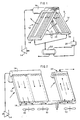
- Figure 1 illustrates a previously-proposed air-cooled steam condenser;
- Figure 2 illustrates another previously-proposed air-cooled steam condenser;
- Figure 3 illustrates a further previously-proposed air-cooled steam condenser;
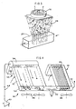
- Figure 4 illustrates an embodiment of the invention;
- Figure 5 illustrates an alternative embodiment of the invention;
- Figure 6 illustrates another alternative embodiment of the invention;
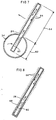
- Figure 7 is a sectional view that illustrates one of the heat pipes used in apparatus embodying the invention;
- Figure 8 is a sectional view of an alternative embodiment of a heat pipe that may be used;
- Figure 9 is a sectional view that illustrates an alternative embodiment of the lower steam header; and
- Figure 10 is a view taken along lines 10-10 in Figure 9.
- As seen in Figure 1, air-cooled steam condensers are typically arranged in an A-frame construction with a
fan 10 at the base and inclinedcondenser tube bundles 12 on each side. Air flows through thefan 10 across several sections of the steam condenser. Steam from asteam turbine 14 is directed to anupper steam header 16 which provides a steam inlet at the top of eachbundle 12. The vapour and condensate flow concurrently downwards in thebundle 12 to a lower orrear header 18. An air ejector orvacuum pump 20 is used to vent noncondensable gases from therear header 18. The condensate is collected in atank 22 and directed to condensate pumps (not shown) for reuse. - Figure 2 illustrates a previously-proposed solution to prevent freezing of condensate. The
condenser tube bundle 12 is designed to cause excess steam flow through each tube row. The excess steam prevents the accumulation of noncondensable gases and maintains condensate temperatures above freezing. This excess steam is condensed in a secondary orvent condenser 24. Thetypical vent condenser 24 is a dephlegmator (reflux condenser) which has steam flow up an inclined tube, condensation on the tube walls, and drainage of the condensate downwardly. The noncondensable gases flow upwards out of the tube and are removed by vacuum pumps or air ejectors. - Figure 3 illustrates another previously-proposed solution to prevent freezing of condensate.
Heat pipes 26 are set up in a Y configuration. The evaporator side of the heat pipes is enclosed in asteam header 28. The steam is condensed as it passes across the evaporator side of theheat pipes 26. The condensate is collected at the bottom of theheader 28 and returned to the boiler for reuse. Thefan 10 causes induced air flow across the condenser sides of the heat pipes to cause cooling and recondensation of the working fluid contained in the heat pipes. - One embodiment of the present invention is shown in Figure 4. A
steam condensing apparatus 30 generally comprises amain condenser 32, alower header 34, and asecondary condenser 36. - The
main condenser 32 is formed from anupper steam header 38 and one ormore tube bundles 40. Theupper steam header 38 receives steam from asteam turbine 42 via aline 44 and then directs the steam into thetube bundles 40. Eachtube bundle 40 is similar to tube bundles generally known and used in the industry in that several rows of tubes, usually four, are provided for receiving and condensing steam. The main difference in the tube bundles of the present apparatus compared to the prior art is that they are not designed to condense as much of the steam as possible. Instead, the heat transfer surface area and fan air flow fromfans 46 are designed such that, over the range of operating conditions, all of the steam does not completely condense and steam vapour continuously exits the bottom of each tube row into thelower header 34. In the preferred embodiment, sixty-seven to eighty percent of the available surface area is used in the tube bundles 40. This surface area, combined with fan air flow, results in approximately twenty to eighty percent of the steam being condensed in themain condenser 32. The continuous flow of steam vapour purges the tube rows in themain condenser 32 of noncondensable gases. The excess uncondensed steam and noncondensable gases flow into thelower header 34 and then to thesecondary condenser 36. - The
secondary condenser 36 is in fluid communication with thelower header 34 and positioned in line with themain condenser 32.Heat pipes 48 are positioned in thesecondary condenser 36 such that the evaporator side of each heat pipe is at the lower end of thesecondary condenser 36, and extends into thelower header 34. The condenser side of each heat pipe is positioned towards the upper end of thesecondary condenser 36. In this manner, the uncondensed steam from themain condenser 32 condenses on the evaporator side of theheat pipes 48 and flows out of thelower header 34 through acondensate drain 50. Noncondensable gases are vented off to anejector 52. - Figure 5 illustrates an alternative embodiment of the invention wherein the
main condenser 32 and thesecondary condenser 36 are oriented in a W-shaped configuration instead of an in-line configuration. As above, the apparatus condenses the excess steam in thesecondary condenser 36. Noncondensable gases are vented off vialines 54. - Figure 6 illustrates another alternative embodiment of the invention wherein the main and secondary condensers described above are consolidated into a
single condenser 56. Thesingle condenser 56 includes conventionalfinned tubes 58 that direct steam flow from top to bottom, andheat pipes 26. As before, the heat transfer surface area and fan air flow are designed such that, over the range of operating conditions, all of the steam is not condensed in thetubes 58. The continuous flow of steam purges thetubes 58 of noncondensable gases. The remaining steam that exits the bottom of thetubes 58 is condensed by theheat pipes 26 which have their evaporator side extending below the exit end of thetubes 58 in thelower header 34. Condensate drains from thecondensate drain 50 to be collected for reuse. Noncondensable gases are removed via the vent lines 54. Figure 6 illustrates four rows of pipes, with theheat pipes 26 being the lower or first row. It should be understood that theheat pipes 26 may be positioned in any row of the tube bundle. - Figure 7 is a detailed sectional view of one of the
heat pipes 26 and thelower header 34. Theheat pipes 26 may be fabricated out of straight round, elliptical, or flat oval tubes that may or may not contain an internal wick. Theheat pipes 26 are sealed at both ends and contain a predetermined quantity ofheat transfer fluid 60 at a predetermined vapour pressure. The fluid used will depend upon the application and conditions. Examples of heat transfer fluids used in different heat pipe applications include, but are not limited to, methanol, ammonia and freon. Theheat transfer fluid 60 normally resides in theevaporator section 62 of theheat pipe 26. When heat flows into theevaporator section 62, theheat transfer fluid 60 vapourizes, removing heat from the steam and causing condensation thereof, and travels upwards into thecondenser section 64 where the fluid is cooled and condensed, releasing the fluid heat to the air flow. The heat transfer fluid condensate returns to theevaporator section 62 by gravity flow. Thecondenser section 64 may be provided withfins 66 to provide a large heat rejection surface area. Thefins 66 may be extruded, embedded, or wrapped aluminium or steel, and can be solid or serrated depending upon the pressure drop and heat transfer requirements. Theheat pipes 26 may be placed in inline or triangular tube pitches depending upon the pressure drop and heat transfer requirements of the system. - For improved heat transfer performance and corrosion resistance, the system shown in Figure 8 includes a
heat pipe 26 that has the outer diameter of the evaporator section sleeved with a low friction coating 68 such as polytetrafluoroethylene. Thelow friction coating 68 promotes drop-wise condensation which improves the condensing heat transfer rate by about one order of magnitude. In addition, the coating provides a corrosion-proof boundary that allows the use of inexpensive carbon steel based tubes for theheat pipes 26. - Figures 9 and 10 illustrate an embodiment of the
lower header 34 that is provided with a plurality of thermowells orsleeves 70 that are welded directly to thelower header 34 to form a leak-proof seal. Eachsleeve 70 is sized to provide a small slip-fit clearance between the inner diameter of thesleeve 70 and the outer diameter of the evaporator section of theheat pipe 26, so as to reduce thermal resistance. If required to improve heat transport, a thermally conductive substance such as grease or a suitable liquid may be used to fill the annulus. Theheat pipes 26 are held in place by gravity and by the tube supports (not shown) commonly found in the condenser bundle frame. This provides another means of eliminating corrosive contact of theheat pipes 26 with the steam. As referred to above, the exterior of thesleeves 70 may be coated with a low friction coating to promote drop-wise condensation, thus improving the condensing heat transfer rate. - In operation, steam received in the
upper header 38 flows into the tubes in the tube bundles 40 where some of the steam is condensed and flows into thelower header 34. The remaining steam flowing out of the tubes into thelower header 34 purges the tubes of noncondensable gases. The remaining steam is condensed in theevaporator section 62 of theheat pipes 26. Noncondensable gases are removed via the vent lines and/or vacuum pumps. The arrangement of tubes and heat pipes causes a constant steam flow through the tubes in the tube bundles to provide for freeze-proof tubes in the tube bundles. The only freezing possible in the design of the apparatus is on the outside of the heat pipe section located in the lower header. Since this occurs on the exterior of the heat pipes, it will not damage the heat pipes. The lower header embodiment of Figure 9 provides the advantage of being able to remove and install heat pipes in the field without the need to cut and reweld the difficult seal weld between theheat pipe 26 and thelower header 34. - Because many varying and differing embodiments may be made within the scope of the inventive concept herein taught and because many modifications may be made in the embodiments herein detailed, it is to be understood that the details herein are to be interpreted as illustrative and not in a limiting sense.
Claims (12)
- A steam condensing apparatus comprising:an upper steam header (38);a main condenser (32) in fluid communication with said upper steam header (38), said main condenser (32) being designed such that only a predetermined portion of the steam flow therethrough is condensed therein;a lower steam header (34) in fluid communication with said main condenser (32);a secondary condenser (36) in fluid communication with said lower steam header (34); anda plurality of heat pipes (48) received in said secondary condenser (36) that cause condensation of steam not condensed in said main condenser (32).
- A steam condensing apparatus according to claim 1, wherein said main condenser (32) is designed such that approximately twenty to eighty percent of the steam flow therethrough is condensed.
- A steam condensing apparatus according to claim 1 or claim 2, wherein said main condenser (32) and secondary condenser (36) are arranged in an inline configuration.
- A steam condensing apparatus according to claim 1 or claim 2, wherein said main condenser (32) and secondary condenser (36) are arranged in a W-shaped configuration.
- A steam condensing apparatus according to any one of the preceding claims, wherein said heat pipes (26) are provided with a low friction coating (68) on the evaporator section thereof.
- A steam condensing apparatus according to any one of the preceding claims, wherein said lower steam header (34) is provided with a plurality of sleeves (70) that extend into said lower steam header (34) and are each sized to receive the evaporator section of one of said heat pipes (26).
- A steam condensing apparatus comprising:an upper steam header (38);a main condenser (32) in fluid communication with said upper steam header (38), said main condenser (32) being designed such as to condense approximately twenty to eighty percent of the steam flow therethrough;a lower steam header (34) in fluid communication with said main condenser (32);a secondary condenser (36) in fluid communication with said lower steam header (34) and positioned in line with said main condenser (32); anda plurality of heat pipes (48) received in said secondary condenser (36) that cause condensation of steam not condensed in said main condenser (32).
- A steam condensing apparatus according to claim 7, wherein said heat pipes (26) are provided with a low friction coating (68) on the evaporator section thereof.
- A steam condensing apparatus according to claim 7 or claim 8, wherein said lower steam header (34) is provided with a plurality of sleeves (70) that extend into said lower steam header (34) and are each sized to receive the evaporator section of one of said heat pipes (26).
- A steam condensing apparatus comprising:an upper steam header (38);a lower steam header (34);a condenser (56) positioned between said upper and lower steam headers (38,34);a plurality of steam tubes (58) positioned in said condenser (56) and in fluid communication with said upper steam header (38) and said lower steam header (34); anda plurality of heat pipes (26) positioned in said condenser (56) such that the evaporator sections of said heat pipes (26) extend into said lower steam header (34).
- A steam condensing apparatus according to claim 10, wherein the evaporator section of each of said heat pipes (26) is provided with a low friction coating (68).
- A steam condensing apparatus according to claim 10 or claim 11, wherein said lower steam header (34) is provided with a plurality of sleeves (70) that extend into said lower steam header (34) and are each sized to receive the evaporator section of one of said heat pipes (26).
Applications Claiming Priority (2)
| Application Number | Priority Date | Filing Date | Title |
|---|---|---|---|
| US61056796A | 1996-03-06 | 1996-03-06 | |
| US610567 | 1996-03-06 |
Publications (2)
| Publication Number | Publication Date |
|---|---|
| EP0794401A2 true EP0794401A2 (en) | 1997-09-10 |
| EP0794401A3 EP0794401A3 (en) | 1998-09-23 |
Family
ID=24445557
Family Applications (1)
| Application Number | Title | Priority Date | Filing Date |
|---|---|---|---|
| EP97300956A Withdrawn EP0794401A3 (en) | 1996-03-06 | 1997-02-14 | Steam condensing apparatus |
Country Status (9)
| Country | Link |
|---|---|
| EP (1) | EP0794401A3 (en) |
| JP (1) | JP2807992B2 (en) |
| KR (1) | KR100250863B1 (en) |
| AU (1) | AU690048B2 (en) |
| BR (1) | BR9701200A (en) |
| CA (1) | CA2199209C (en) |
| ID (1) | ID16111A (en) |
| SG (1) | SG54463A1 (en) |
| TW (1) | TW360769B (en) |
Cited By (16)
| Publication number | Priority date | Publication date | Assignee | Title |
|---|---|---|---|---|
| EP2149682A1 (en) * | 2008-07-29 | 2010-02-03 | General Electric Company | Condenser for a combined cycle power plant |
| US8015790B2 (en) | 2008-07-29 | 2011-09-13 | General Electric Company | Apparatus and method employing heat pipe for start-up of power plant |
| US8157512B2 (en) | 2008-07-29 | 2012-04-17 | General Electric Company | Heat pipe intercooler for a turbomachine |
| US8186152B2 (en) | 2008-07-23 | 2012-05-29 | General Electric Company | Apparatus and method for cooling turbomachine exhaust gas |
| US8359824B2 (en) | 2008-07-29 | 2013-01-29 | General Electric Company | Heat recovery steam generator for a combined cycle power plant |
| US8425223B2 (en) | 2008-07-29 | 2013-04-23 | General Electric Company | Apparatus, system and method for heating fuel gas using gas turbine exhaust |
| US8596073B2 (en) | 2008-07-18 | 2013-12-03 | General Electric Company | Heat pipe for removing thermal energy from exhaust gas |
| CN103977891A (en) * | 2013-02-11 | 2014-08-13 | 通用电气公司 | Systems and methods for coal beneficiation |
| EP2429690A4 (en) * | 2009-05-15 | 2014-09-24 | Spx Cooling Technologies Inc | AIR COOLED WATER VAPOR CONDENSER WITH NATURAL DRAWING AND METHOD |
| EP2635865A4 (en) * | 2010-11-03 | 2014-11-05 | Spx Cooling Technologies Inc | CONDENSER WITH NATURAL DRAW |
| CN105833582A (en) * | 2016-05-23 | 2016-08-10 | 沈玮 | Rapid cooling device for biological medical technique |
| CN108917418A (en) * | 2018-08-02 | 2018-11-30 | 山西大学 | A kind of Air-Cooling Island fair current tube bank vacuum evacuation device |
| EP3480548A1 (en) * | 2017-11-07 | 2019-05-08 | SPX Dry Cooling Belgium sprl | Three-stage heat exchanger for an air-cooled condenser |
| CN113035386A (en) * | 2021-03-05 | 2021-06-25 | 哈尔滨工程大学 | Containment built-in efficient heat exchanger adopting double-wheel double-blade composite power air suction type |
| CN113532141A (en) * | 2020-04-20 | 2021-10-22 | 齐秀 | Anti-freezing method for air cooling island in alpine region |
| US11703285B1 (en) * | 2023-02-27 | 2023-07-18 | Helen Skop | Apparatus and method for latent energy exchange |
Families Citing this family (7)
| Publication number | Priority date | Publication date | Assignee | Title |
|---|---|---|---|---|
| DE202005005302U1 (en) * | 2005-04-04 | 2005-06-02 | Spx-Cooling Technologies Gmbh | air condenser |
| BR112014000879A2 (en) * | 2011-07-15 | 2017-02-21 | Univ Stellenbosch | deflegmator |
| CN102788516A (en) * | 2012-09-11 | 2012-11-21 | 哈尔滨工业大学(威海) | Direct air cooling condenser unit for power station |
| CN103697639B (en) * | 2013-12-12 | 2016-03-02 | 华南理工大学 | A kind of Absorption Refrigerator condenser based on having strengthening coagulation heat pipe bundle |
| RU184773U1 (en) * | 2018-06-15 | 2018-11-08 | Федеральное государственное бюджетное образовательное учреждение высшего образования "Калининградский государственный технический университет" | INSTALLING NATURAL GAS COOLING |
| KR102055708B1 (en) * | 2018-06-26 | 2019-12-13 | 동일플랜트 주식회사 | Draft type condenser with improved of cooling efficiency by using heat pipe inserted in the steam turbine output steam pipe |
| CN111397389B (en) * | 2020-03-20 | 2021-07-27 | 太原理工大学 | A Direct Air Cooling System for Power Plants Preventing Tube Bundle Freeze |
Family Cites Families (6)
| Publication number | Priority date | Publication date | Assignee | Title |
|---|---|---|---|---|
| US4149588A (en) * | 1976-03-15 | 1979-04-17 | Mcdonnell Douglas Corporation | Dry cooling system |
| IT1135516B (en) * | 1981-02-18 | 1986-08-27 | Nuovo Pignone Spa | PERFECTED STEAM CONDENSER WITH AIR COOLING |
| DE3106973C2 (en) * | 1981-02-25 | 1985-03-07 | Balcke-Dürr AG, 4030 Ratingen | Air-cooled condensation system |
| DE3114948C2 (en) * | 1981-04-13 | 1985-05-02 | Balcke-Dürr AG, 4030 Ratingen | Air-cooled condensation system |
| SU1326864A1 (en) * | 1985-01-18 | 1987-07-30 | А. А. Бородин и С..С. Ясаков | Cooling device |
| SU1672187A1 (en) * | 1989-09-27 | 1991-08-23 | Всесоюзный государственный научно-исследовательский и проектно-изыскательский институт "Теплоэлектропроект" | Cooling unit |
-
1997
- 1997-02-14 EP EP97300956A patent/EP0794401A3/en not_active Withdrawn
- 1997-02-15 SG SG1997000345A patent/SG54463A1/en unknown
- 1997-02-20 KR KR1019970005136A patent/KR100250863B1/en not_active Expired - Fee Related
- 1997-02-25 JP JP9055424A patent/JP2807992B2/en not_active Expired - Lifetime
- 1997-03-03 ID IDP970656A patent/ID16111A/en unknown
- 1997-03-04 AU AU15093/97A patent/AU690048B2/en not_active Ceased
- 1997-03-05 CA CA002199209A patent/CA2199209C/en not_active Expired - Fee Related
- 1997-03-05 BR BR9701200A patent/BR9701200A/en not_active IP Right Cessation
- 1997-03-13 TW TW086103123A patent/TW360769B/en active
Cited By (22)
| Publication number | Priority date | Publication date | Assignee | Title |
|---|---|---|---|---|
| US8596073B2 (en) | 2008-07-18 | 2013-12-03 | General Electric Company | Heat pipe for removing thermal energy from exhaust gas |
| US8186152B2 (en) | 2008-07-23 | 2012-05-29 | General Electric Company | Apparatus and method for cooling turbomachine exhaust gas |
| US8015790B2 (en) | 2008-07-29 | 2011-09-13 | General Electric Company | Apparatus and method employing heat pipe for start-up of power plant |
| US8157512B2 (en) | 2008-07-29 | 2012-04-17 | General Electric Company | Heat pipe intercooler for a turbomachine |
| US8359824B2 (en) | 2008-07-29 | 2013-01-29 | General Electric Company | Heat recovery steam generator for a combined cycle power plant |
| US8425223B2 (en) | 2008-07-29 | 2013-04-23 | General Electric Company | Apparatus, system and method for heating fuel gas using gas turbine exhaust |
| EP2149682A1 (en) * | 2008-07-29 | 2010-02-03 | General Electric Company | Condenser for a combined cycle power plant |
| EP2429690A4 (en) * | 2009-05-15 | 2014-09-24 | Spx Cooling Technologies Inc | AIR COOLED WATER VAPOR CONDENSER WITH NATURAL DRAWING AND METHOD |
| EP2635865A4 (en) * | 2010-11-03 | 2014-11-05 | Spx Cooling Technologies Inc | CONDENSER WITH NATURAL DRAW |
| US20140223882A1 (en) * | 2013-02-11 | 2014-08-14 | General Electric Company | Systems and methods for coal beneficiation |
| CN103977891A (en) * | 2013-02-11 | 2014-08-13 | 通用电气公司 | Systems and methods for coal beneficiation |
| CN105833582A (en) * | 2016-05-23 | 2016-08-10 | 沈玮 | Rapid cooling device for biological medical technique |
| US11378339B2 (en) | 2017-11-07 | 2022-07-05 | Spg Dry Cooling Belgium | Three-stage heat exchanger for an air-cooled condenser |
| EP3480548A1 (en) * | 2017-11-07 | 2019-05-08 | SPX Dry Cooling Belgium sprl | Three-stage heat exchanger for an air-cooled condenser |
| WO2019091869A1 (en) * | 2017-11-07 | 2019-05-16 | Spx Dry Cooling Belgium | Three-stage heat exchanger for an air-cooled condenser |
| KR20200085283A (en) * | 2017-11-07 | 2020-07-14 | 에스피쥐 드라이 쿨링 벨지엄 | 3-stage heat exchanger for air-cooled condensers |
| KR102662738B1 (en) | 2017-11-07 | 2024-05-07 | 에스피쥐 드라이 쿨링 벨지엄 | Three-stage heat exchanger for air-cooled condensers |
| CN108917418A (en) * | 2018-08-02 | 2018-11-30 | 山西大学 | A kind of Air-Cooling Island fair current tube bank vacuum evacuation device |
| CN113532141A (en) * | 2020-04-20 | 2021-10-22 | 齐秀 | Anti-freezing method for air cooling island in alpine region |
| CN113035386A (en) * | 2021-03-05 | 2021-06-25 | 哈尔滨工程大学 | Containment built-in efficient heat exchanger adopting double-wheel double-blade composite power air suction type |
| CN113035386B (en) * | 2021-03-05 | 2022-11-18 | 哈尔滨工程大学 | A high-efficiency heat exchanger built into the containment using a double-wheel and double-blade composite power suction type |
| US11703285B1 (en) * | 2023-02-27 | 2023-07-18 | Helen Skop | Apparatus and method for latent energy exchange |
Also Published As
| Publication number | Publication date |
|---|---|
| AU1509397A (en) | 1997-10-09 |
| MX9701495A (en) | 1998-06-28 |
| SG54463A1 (en) | 1998-11-16 |
| BR9701200A (en) | 1998-12-15 |
| ID16111A (en) | 1997-09-04 |
| AU690048B2 (en) | 1998-04-09 |
| EP0794401A3 (en) | 1998-09-23 |
| CA2199209C (en) | 2000-05-16 |
| TW360769B (en) | 1999-06-11 |
| KR100250863B1 (en) | 2000-04-01 |
| JPH102683A (en) | 1998-01-06 |
| JP2807992B2 (en) | 1998-10-08 |
| CA2199209A1 (en) | 1997-09-06 |
| KR970066264A (en) | 1997-10-13 |
Similar Documents
| Publication | Publication Date | Title |
|---|---|---|
| CA2199209C (en) | Steam condensing apparatus | |
| JP4331689B2 (en) | Combined air-cooled condenser | |
| RU2734089C2 (en) | Industrial steam condenser with completely secondary air cooling | |
| US6332494B1 (en) | Air-cooled condenser | |
| US5115645A (en) | Heat exchanger for refrigerant recovery system | |
| US4905474A (en) | Air-cooled vacuum steam condenser | |
| US6241009B1 (en) | Integrated heat pipe vent condenser | |
| US5787970A (en) | Air-cooled vacuum steam condenser with mixed flow bundle | |
| US8157898B2 (en) | Condenser | |
| RU2190173C2 (en) | Air-cooled condenser | |
| AU610358B2 (en) | Heat exchanger for condensing vapor containing non- condensable gases | |
| US6296049B1 (en) | Condenser | |
| CN1162103A (en) | Steam condensing apparatus | |
| CN101031767B (en) | Steam condenser with two channels | |
| US8833082B2 (en) | Natural draft condenser | |
| KR20260032452A (en) | Cooling system for immersion cooling of electronic components | |
| EP0346848B1 (en) | Air-cooled vacuum steam condenser | |
| JP2025528559A (en) | Air condensers for organic Rankine cycle plants. | |
| MXPA97001495A (en) | Va condenser appliance | |
| JP3697331B2 (en) | Condenser | |
| US5159975A (en) | Unit to enhance heat transfer through heat exchanger tube | |
| JPS5947836B2 (en) | steam condenser | |
| RU2126287C1 (en) | Air-cooled condenser | |
| SU1672187A1 (en) | Cooling unit | |
| EP0074384B1 (en) | Heat exchanger |
Legal Events
| Date | Code | Title | Description |
|---|---|---|---|
| PUAI | Public reference made under article 153(3) epc to a published international application that has entered the european phase |
Free format text: ORIGINAL CODE: 0009012 |
|
| AK | Designated contracting states |
Kind code of ref document: A2 Designated state(s): DE ES FR GB IT |
|
| PUAL | Search report despatched |
Free format text: ORIGINAL CODE: 0009013 |
|
| AK | Designated contracting states |
Kind code of ref document: A3 Designated state(s): DE ES FR GB IT |
|
| 17P | Request for examination filed |
Effective date: 19990301 |
|
| 17Q | First examination report despatched |
Effective date: 20000307 |
|
| STAA | Information on the status of an ep patent application or granted ep patent |
Free format text: STATUS: THE APPLICATION IS DEEMED TO BE WITHDRAWN |
|
| 18D | Application deemed to be withdrawn |
Effective date: 20000718 |