EP2634819A1 - Photovoltaic equipment - Google Patents
Photovoltaic equipment Download PDFInfo
- Publication number
- EP2634819A1 EP2634819A1 EP11836167.4A EP11836167A EP2634819A1 EP 2634819 A1 EP2634819 A1 EP 2634819A1 EP 11836167 A EP11836167 A EP 11836167A EP 2634819 A1 EP2634819 A1 EP 2634819A1
- Authority
- EP
- European Patent Office
- Prior art keywords
- sheet
- lens sheet
- fresnel lens
- fixing portion
- multiple fresnel
- Prior art date
- Legal status (The legal status is an assumption and is not a legal conclusion. Google has not performed a legal analysis and makes no representation as to the accuracy of the status listed.)
- Withdrawn
Links
Images



Classifications
-
- H—ELECTRICITY
- H10—SEMICONDUCTOR DEVICES; ELECTRIC SOLID-STATE DEVICES NOT OTHERWISE PROVIDED FOR
- H10F—INORGANIC SEMICONDUCTOR DEVICES SENSITIVE TO INFRARED RADIATION, LIGHT, ELECTROMAGNETIC RADIATION OF SHORTER WAVELENGTH OR CORPUSCULAR RADIATION
- H10F77/00—Constructional details of devices covered by this subclass
- H10F77/60—Arrangements for cooling, heating, ventilating or compensating for temperature fluctuations
- H10F77/63—Arrangements for cooling directly associated or integrated with photovoltaic cells, e.g. heat sinks directly associated with the photovoltaic cells or integrated Peltier elements for active cooling
-
- H—ELECTRICITY
- H10—SEMICONDUCTOR DEVICES; ELECTRIC SOLID-STATE DEVICES NOT OTHERWISE PROVIDED FOR
- H10P—GENERIC PROCESSES OR APPARATUS FOR THE MANUFACTURE OR TREATMENT OF DEVICES COVERED BY CLASS H10
- H10P50/00—Etching of wafers, substrates or parts of devices
- H10P50/60—Wet etching
- H10P50/64—Wet etching of semiconductor materials
- H10P50/642—Chemical etching
-
- H—ELECTRICITY
- H02—GENERATION; CONVERSION OR DISTRIBUTION OF ELECTRIC POWER
- H02S—GENERATION OF ELECTRIC POWER BY CONVERSION OF INFRARED RADIATION, VISIBLE LIGHT OR ULTRAVIOLET LIGHT, e.g. USING PHOTOVOLTAIC [PV] MODULES
- H02S30/00—Structural details of PV modules other than those related to light conversion
- H02S30/10—Frame structures
-
- H—ELECTRICITY
- H10—SEMICONDUCTOR DEVICES; ELECTRIC SOLID-STATE DEVICES NOT OTHERWISE PROVIDED FOR
- H10F—INORGANIC SEMICONDUCTOR DEVICES SENSITIVE TO INFRARED RADIATION, LIGHT, ELECTROMAGNETIC RADIATION OF SHORTER WAVELENGTH OR CORPUSCULAR RADIATION
- H10F77/00—Constructional details of devices covered by this subclass
- H10F77/40—Optical elements or arrangements
- H10F77/42—Optical elements or arrangements directly associated or integrated with photovoltaic cells, e.g. light-reflecting means or light-concentrating means
- H10F77/484—Refractive light-concentrating means, e.g. lenses
-
- Y—GENERAL TAGGING OF NEW TECHNOLOGICAL DEVELOPMENTS; GENERAL TAGGING OF CROSS-SECTIONAL TECHNOLOGIES SPANNING OVER SEVERAL SECTIONS OF THE IPC; TECHNICAL SUBJECTS COVERED BY FORMER USPC CROSS-REFERENCE ART COLLECTIONS [XRACs] AND DIGESTS
- Y02—TECHNOLOGIES OR APPLICATIONS FOR MITIGATION OR ADAPTATION AGAINST CLIMATE CHANGE
- Y02E—REDUCTION OF GREENHOUSE GAS [GHG] EMISSIONS, RELATED TO ENERGY GENERATION, TRANSMISSION OR DISTRIBUTION
- Y02E10/00—Energy generation through renewable energy sources
- Y02E10/50—Photovoltaic [PV] energy
- Y02E10/52—PV systems with concentrators
Definitions
- the present invention relates to a photovoltaic unit using a resin Fresnel lens, in particular, to one incorporating an integrated multiple Fresnel lens sheet.
- Patent Document 1 discloses a collector in which a large number of light-collecting Fresnel lenses are arranged on the same plane and each solar cell is arranged at the focus position of each Fresnel lens as a unit.
- the Fresnel lenses for such a collector are generally formed by casting, injection molding, press molding, or transcription molding as photopolymerization (2P) using a UV curable resin, using a metal mold cut from a cut metal plate with a lathe.
- the lenses can be individually mounted in frames.
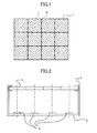
- a large number of light-collecting Fresnel lenses (unit lenses) in FIG. 1 be arranged on the same plane to form a sheet (hereinafter, multiple Fresnel lens sheet) and fix it in a frame.
- FIG. 2 schematically shows an example of a photovoltaic unit as seen from the cross section of a Fresnel lens sheet. It includes a base plate 2 (hereinafter may be referred to as solar cell plate) on which solar cells 3 are arranged and a multiple Fresnel lens sheet 1 on a light incidence side of the solar cells 3. The sheet is supported in a frame 4 so that each of the solar cells is disposed at the focus position of each Fresnel lens.
- a base plate 2 hereinafter may be referred to as solar cell plate
- the Fresnel lens sheet 1 and frame 4 may be damaged by a difference in elasticity due to a temperature or humidity change if the sheet and frame are too firmly fixed. In view of this, it is preferable that the sheet is movably held in a planar direction. Further, the solar cells are often placed on a metal plate for the purpose of heat radiation.
- FIG. 8 shows the structure which can achieve both of the above, for example.
- a seal element 8 is provided at one end of the sheet 1 and the sheet 1 and a metal frame 7 are fixed with a screw 6.
- the sheet can be fixed along the thickness with a sufficiently reduced gap and at the same time it is movable in a planar direction.
- the multiple Fresnel lens sheet and frame are in general made from different materials from those of the base plate on which the solar cells are disposed so that with a change in temperature or humidity, they differently behave in terms of elasticity. This may cause a displacement of the focus position of each unit lens from the solar cell, resulting in a decrease in the power generation efficiency. This is particularly significant for a resin Fresnel lens sheet.
- the sheet in FIG. 8 expands and shrinks radially around a single point most firmly fixed on the frame. Therefore, a problem arises that the focus position of the unit lens in the portion furthest from the single point is greatly shifted from the corresponding solar cell. Moreover, it is difficult to estimate which portion of the sheet will be the center point of expansion and design the sheet with the displacement taken into consideration. With use of a rectangular multiple Fresnel lens sheet, if the center point falls in the vicinity of any of the four corners, the focus position in the opposite corner will be most displaced from the solar cell.
- An object of the present invention is to minimally reduce a displacement of the focus positions of the lenses from the solar cells even if the Fresnel lens sheet and the base plate on which the solar cells are arranged elastically behave differently due to temperature or humidity changes, as well as to prevent a decrease in power generation efficiency.
- a photovoltaic unit which comprises an integrated multiple Fresnel lens sheet and a base plate on which solar cells are arranged adjacent to a focus position of each Fresnel lens, wherein the multiple Fresnel lens sheet is fixed to the base plate at a lens sheet fixing portion adjacent to a center of gravity of the sheet.
- the lens sheet fixing portion is adjacent to the center of gravity of the sheet and at a boundary of individual Fresnel lenses.
- the multiple Fresnel sheet can have a second fixing portion in addition to the lens sheet fixing portion, and the multiple Fresnel sheet is movable only in a direction connecting the lens sheet fixing portion and the second fixing portion.
- the second fixing portion can be adjacent to an end of the entire multiple Fresnel lens sheet.
- the present invention it is possible to minimally reduce a displacement of the focus positions of the individual Fresnel lenses from the solar cells even if the Fresnel lens sheet expands or shrinks due to a temperature or humidity change.
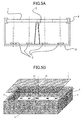
- FIG. 3 shows that the multiple Fresnel lens sheet 1 of the photovoltaic unit in FIG. 2 has shrunk relative to the base plate 2 because of a change in temperature or humidity.
- the center or the focus position of a Fresnel lens 11 at the right end of the drawing is greatly shifted relative to a corresponding solar cell, reducing the power generation efficiency.
- FIG. 4 shows the multiple Fresnel lens sheet according to an example of the present invention which includes a lens sheet fixing portion 51 adjacent to the center of gravity on the sheet surface.
- the lens sheet is fixed to the solar cell plate 2 via a lens sheet fixing element 5 as shown in FIGs. 5A, 5B .
- adjacent to the center of gravity refers to being in a distance between the centers of neighboring unit lenses from the center of gravity of the multiple Fresnel lens sheet 1.
- FIG. 5A shows that the multiple Fresnel lens sheet 1 of the photovoltaic unit according to the present embodiment has shrunk relative to the base plate 2 because of a change in temperature or humidity. A shift in the center or the focus position of each Fresnel lens 11 in the right and left ends relative to a corresponding solar cell is relatively small, reducing a decrease in the power generation efficiency.
- a lens sheet fixing portion 51 is provided on the surface of the multiple Fresnel lens sheet near the center of gravity. Because of a general rectangular shape thereof, the center of gravity is at the center of the line connecting the centers of long sides of the multiple Fresnel lens sheet as shown in FIG. 4 . In forming the multiple Fresnel lens sheet, a small non-use area in which no lenses are formed may occur at the joints of lenses or lens molds. It is preferable to provide the lens sheet fixing portion in such a non-use area.
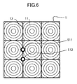
- FIG. 6 shows two examples, a lens sheet fixing portion 511 provided at the boundary 12 of the two sides of the two unit lenses and a lens sheet fixing portion 512 provided at the boundary 12 of the four corners of the four unit lenses.
- the lens sheet fixing element 5 is preferably provided in a portion other than a pyramid-like focus area whose bottom side is the Fresnel lens 11 and apex is the solar cell 3, as shown in FIG. 5A . Further, with the multiple Fresnel lens sheet fixed at the lens sheet fixing portion 51 as shown in FIG. 5B , the lens sheet fixing element 5 is preferably of a beam structure disposed below the multiple Fresnel lens sheet 1 to be able to prevent a flexure of the sheet by its own weight.
- the present invention is applicable to each of divided multiple Fresnel lens sheets of a large-size photovoltaic unit using solar cells 3 in an 8-by-8 or more matrix.
- a large-size photovoltaic unit with solar cells 3 in a 12-by-12 matrix two multiple Fresnel lens sheets 1 in a 6-by-12 matrix are fixed in the vicinity of the respective centers of gravity.
- four multiple Fresnel lens sheets in a 6-by-6 matrix can be fixed in the vicinity of the respective centers of gravity.
- a warpage may occur in the sheet because of thermal expansion or expansion by water absorption.
- a seal element which enables fixation with no adhesive can be provided on both or at least either of the sheet and the frame element.
- the seal element is preferably a flexible element with less friction resistance, for example.
- each of the solar cells 3 can include a secondary optical collector to compensate for the displacement of the focus position.
- the sheet can include a second fixing portion 52 not to hinder the elasticity of the sheet in addition to the lens sheet fixing portion adjacent to the center of gravity of the sheet.
- the second fixing portion 52 is, for example, preferably placed on the line in elastic direction (radial direction) around the lens sheet fixing portion and configured to prevent the sheet from rotating about the lens sheet fixing portion 51 as a rotational axis without hindering the elasticity of the sheet.
- the second fixing portion is placed near the end of the entire multiple Fresnel sheet. Thereby, it is possible to effectively prevent the sheet from rotating about the lens sheet fixing portion.
- the second fixing portion is a notch at the end of the entire multiple Fresnel sheet. By covering the notch with the frame element in which the multiple Fresnel sheet is fixed, it can prevent dust or water from entering the notch.
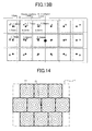
- the outer form of the multiple Fresnel lens sheet is not limited to a rectangle, as shown in FIG. 14 , for example.
- the rectangle indicated by the thin line surrounding the entire Fresnel lens sheet in FIG. 14 is regarded as outer form, for instance.
- FIG. 10A shows the results of calculation using the multiple Fresnel lens sheet in 6 columns and 3 rows in FIG. 9 structured as below and fixed at the center of the sheet when ambient condition is changed from 25 degC * 0% RH to 65 degC * 85% RH.
- Outer form of sheet rectangle in 715 mm by 1,350 mm Size of unit Fresnel lens: square in 225 mm by 225 mm Gap between unit Fresnel lenses: vertically 20 mm, horizontally 0 mm
- FIG. 13B shows the results of calculation using the same lens sheet as in the first example when ambient condition is changed from 25 degC * 0%RH to 25 degC * 85%RH.
- FIG. 13A shows the results of calculation using three multiple Fresnel lens sheets structured as below, arranged in 2 columns and 3 rows without a gap and fixed at the center of the sheet when ambient condition is changed from 25 degC * 0%RH to 25 degC * 85%RH.
- Outer form of sheet rectangle in 715 mm by 450 mm
- Size of unit Fresnel lens square in 225 mm by 225 mm
- Gap between unit Fresnel lenses vertically 20 mm, horizontally 0 mm
- a multiple Fresnel lens sheet in 6 columns, 3 rows as structured below was formed by injection molding with a metal mold.
- Resin acrylic resin, Parapet® manufactured by Kuraray Co. Ltd.
- Outer form of sheet rectangle in 715 mm by 1,350 mm Size of unit Fresnel lens: square in 225 mm by 225 mm Gap between unit Fresnel lenses: vertically 20 mm, horizontally 0 mm
- Material of frame and solar cell plate aluminum
- FIG. 10B shows measured values of changes in the positions of unit Fresnel lenses and corresponding solar cells in sheet surface direction immediately after and left at 25 degC * 0%RH and at 85 degC * 0%RH for ten days, when the sheet was fixed at the center. It is understood from the drawing that the results obtained in the first example match those in the first example.
- FIG. 11 shows the results of calculation using the same multiple Fresnel lens sheet as in the first example when the sheet is fixed at the center of the long side of the sheet.
- FIG. 12 shows the results of calculation using the same multiple Fresnel lens sheet as in the first example when the sheet is fixed at the bottom right end of the sheet.
- the values of the unit lenses 4, 5 and else are omitted.
- the present invention can achieve a reduction to a minimum in the displacement of the focus positions from the solar cells and prevention of a decrease in the power generation efficiency even if the elastic behavior of the Fresnel lens sheet under a temperature or humidity change differs from that of the base plate on which the solar cells are disposed.
Landscapes
- Photovoltaic Devices (AREA)
Abstract
Description
- The present invention relates to a photovoltaic unit using a resin Fresnel lens, in particular, to one incorporating an integrated multiple Fresnel lens sheet.
- In recent years the use of natural energy as renewable source of power has received great attention. One example is power generation with photovoltaic cells (solar cells), utilizing solar radiation. To increase the amount of power generation, a collector including reflective mirrors and lenses in combination to collect light on solar cells has been proposed (refer to Patent Document 1). For example,
Patent Document 2 discloses a collector in which a large number of light-collecting Fresnel lenses are arranged on the same plane and each solar cell is arranged at the focus position of each Fresnel lens as a unit. The Fresnel lenses for such a collector are generally formed by casting, injection molding, press molding, or transcription molding as photopolymerization (2P) using a UV curable resin, using a metal mold cut from a cut metal plate with a lathe. - To arrange the solar cells at the focus positions of the Fresnel lenses, the lenses can be individually mounted in frames. For the sake of facilitating manufacturing, it is proposed that a large number of light-collecting Fresnel lenses (unit lenses) in
FIG. 1 be arranged on the same plane to form a sheet (hereinafter, multiple Fresnel lens sheet) and fix it in a frame. - The Fresnel lenses need to be translucent and made from transparent resin or inorganic glass. The transparent resin is preferably used because of light weight and ease of manufacturing.
FIG. 2 schematically shows an example of a photovoltaic unit as seen from the cross section of a Fresnel lens sheet. It includes a base plate 2 (hereinafter may be referred to as solar cell plate) on whichsolar cells 3 are arranged and a multipleFresnel lens sheet 1 on a light incidence side of thesolar cells 3. The sheet is supported in aframe 4 so that each of the solar cells is disposed at the focus position of each Fresnel lens. The Fresnellens sheet 1 andframe 4 may be damaged by a difference in elasticity due to a temperature or humidity change if the sheet and frame are too firmly fixed. In view of this, it is preferable that the sheet is movably held in a planar direction. Further, the solar cells are often placed on a metal plate for the purpose of heat radiation. - Meanwhile, it is necessary to sufficiently reduce a gap between the sheet and the frame in order to prevent rain drops or dust from entering inside which would otherwise cause failures.
FIG. 8 shows the structure which can achieve both of the above, for example. In this structure aseal element 8 is provided at one end of thesheet 1 and thesheet 1 and ametal frame 7 are fixed with ascrew 6. With such a structure the sheet can be fixed along the thickness with a sufficiently reduced gap and at the same time it is movable in a planar direction. - It is essential to accurately set the focus positions of the Fresnel lenses relative to the corresponding solar cells in view of power generation efficiency. However, the multiple Fresnel lens sheet and frame are in general made from different materials from those of the base plate on which the solar cells are disposed so that with a change in temperature or humidity, they differently behave in terms of elasticity. This may cause a displacement of the focus position of each unit lens from the solar cell, resulting in a decrease in the power generation efficiency. This is particularly significant for a resin Fresnel lens sheet.
- With a change in temperature or humidity, the sheet in
FIG. 8 expands and shrinks radially around a single point most firmly fixed on the frame. Therefore, a problem arises that the focus position of the unit lens in the portion furthest from the single point is greatly shifted from the corresponding solar cell.
Moreover, it is difficult to estimate which portion of the sheet will be the center point of expansion and design the sheet with the displacement taken into consideration. With use of a rectangular multiple Fresnel lens sheet, if the center point falls in the vicinity of any of the four corners, the focus position in the opposite corner will be most displaced from the solar cell. -
- Patent Document 1:
U. S. Patent No. 5125983 - Patent Document 2: Japanese Patent Application Publication No.
H11-026800 - An object of the present invention is to minimally reduce a displacement of the focus positions of the lenses from the solar cells even if the Fresnel lens sheet and the base plate on which the solar cells are arranged elastically behave differently due to temperature or humidity changes, as well as to prevent a decrease in power generation efficiency.
- The above object is achieved by a photovoltaic unit which comprises an integrated multiple Fresnel lens sheet and a base plate on which solar cells are arranged adjacent to a focus position of each Fresnel lens, wherein the multiple Fresnel lens sheet is fixed to the base plate at a lens sheet fixing portion adjacent to a center of gravity of the sheet.
- Preferably, the lens sheet fixing portion is adjacent to the center of gravity of the sheet and at a boundary of individual Fresnel lenses.
- Further, the multiple Fresnel sheet can have a second fixing portion in addition to the lens sheet fixing portion, and the multiple Fresnel sheet is movable only in a direction connecting the lens sheet fixing portion and the second fixing portion.
In this case the second fixing portion can be adjacent to an end of the entire multiple Fresnel lens sheet. - According to the present invention, it is possible to minimally reduce a displacement of the focus positions of the individual Fresnel lenses from the solar cells even if the Fresnel lens sheet expands or shrinks due to a temperature or humidity change.
-
-
FIG. 1 shows an example of multiple Fresnel lens sheet; -
FIG. 2 is a cross section view of a photovoltaic unit; -
FIG. 3 shows a positional relation between lenses and a base plate when the lenses shrink relative to the base plate because of a change in temperature and humidity; -
FIG. 4 shows an example of multiple Fresnel lens sheet including a fixing portion; -
FIG. 5A shows a positional relation between a multiple Fresnel lens sheet fixed with a columnar fixing element and a base plate when the sheet shrinks relative to the base plate; -
FIG. 5B shows how to mount the sheet when a fixing element of a beam structure is used by way of example; -
FIG. 6 shows an example of multiple Fresnel lens sheet with a fixing portion in the vicinity of the center of gravity; -
FIG. 7 shows an example of multiple Fresnel lens sheet with a second fixing portion; -
FIG. 8 shows how to fix the multiple Fresnel lens sheet to the frame; -
FIG. 9 shows an example of multiple Fresnel lens sheet in 6 columns and 3 rows; -
FIG. 10A shows calculated values of displacement amount of the multiple Fresnel lens sheet relative to the frame with a change in hygrothermal condition according to a first embodiment; -
FIG. 10B shows measured values of displacement amount of the multiple Fresnel lens sheet relative to the frame with a change in hygrothermal condition according to a fifth embodiment; -
FIG. 11 shows the displacement amount of the multiple Fresnel lens sheet when it is fixed at the center of a long side (first comparison); -
FIG. 12 shows the displacement amount of the multiple Fresnel lens sheet when it is fixed at a bottom right end (second comparison); -
FIG. 13A shows the displacement amount of multiple Fresnel lens sheets in 2 columns and 3 rows when it is fixed at the center (third example); -
FIG. 13B shows the displacement amount of a multiple Fresnel lens sheet in 6 columns and 3 rows when it is fixed at the center (second example); and -
FIG. 14 shows the outer form of another example of multiple Fresnel lens sheet. -
FIG. 3 shows that the multipleFresnel lens sheet 1 of the photovoltaic unit inFIG. 2 has shrunk relative to thebase plate 2 because of a change in temperature or humidity. The center or the focus position of aFresnel lens 11 at the right end of the drawing is greatly shifted relative to a corresponding solar cell, reducing the power generation efficiency. - Meanwhile,
FIG. 4 shows the multiple Fresnel lens sheet according to an example of the present invention which includes a lenssheet fixing portion 51 adjacent to the center of gravity on the sheet surface. The lens sheet is fixed to thesolar cell plate 2 via a lenssheet fixing element 5 as shown inFIGs. 5A, 5B . Note that herein, "adjacent to the center of gravity" refers to being in a distance between the centers of neighboring unit lenses from the center of gravity of the multipleFresnel lens sheet 1.
Now,FIG. 5A shows that the multipleFresnel lens sheet 1 of the photovoltaic unit according to the present embodiment has shrunk relative to thebase plate 2 because of a change in temperature or humidity. A shift in the center or the focus position of eachFresnel lens 11 in the right and left ends relative to a corresponding solar cell is relatively small, reducing a decrease in the power generation efficiency. - According to the present invention a lens
sheet fixing portion 51 is provided on the surface of the multiple Fresnel lens sheet near the center of gravity. Because of a general rectangular shape thereof, the center of gravity is at the center of the line connecting the centers of long sides of the multiple Fresnel lens sheet as shown inFIG. 4 .
In forming the multiple Fresnel lens sheet, a small non-use area in which no lenses are formed may occur at the joints of lenses or lens molds. It is preferable to provide the lens sheet fixing portion in such a non-use area. - Meanwhile, with respect to a multiple Fresnel lens sheet in an odd-number column and an odd-number row, for example, 3 columns, 3 rows in
FIG. 6 , the center thereof comes in the vicinity of the unit lens at the center. In this case it is preferable to provide the lens sheet fixing portion at aboundary 12 of the individual Fresnel lenses which is somewhat away from the center of the multiple Fresnel lens sheet.FIG. 6 shows two examples, a lenssheet fixing portion 511 provided at theboundary 12 of the two sides of the two unit lenses and a lenssheet fixing portion 512 provided at theboundary 12 of the four corners of the four unit lenses. - In terms of preventing interference with optical transmittance, the lens
sheet fixing element 5 is preferably provided in a portion other than a pyramid-like focus area whose bottom side is theFresnel lens 11 and apex is thesolar cell 3, as shown inFIG. 5A .
Further, with the multiple Fresnel lens sheet fixed at the lenssheet fixing portion 51 as shown inFIG. 5B , the lenssheet fixing element 5 is preferably of a beam structure disposed below the multipleFresnel lens sheet 1 to be able to prevent a flexure of the sheet by its own weight. - The present invention is applicable to each of divided multiple Fresnel lens sheets of a large-size photovoltaic unit using
solar cells 3 in an 8-by-8 or more matrix. For example, in a large-size photovoltaic unit withsolar cells 3 in a 12-by-12 matrix, two multipleFresnel lens sheets 1 in a 6-by-12 matrix are fixed in the vicinity of the respective centers of gravity. Alternatively, four multiple Fresnel lens sheets in a 6-by-6 matrix can be fixed in the vicinity of the respective centers of gravity.
Moreover, in adhering the multiple Fresnel lens to a frame element, a warpage may occur in the sheet because of thermal expansion or expansion by water absorption. In view of preventing this, a seal element which enables fixation with no adhesive can be provided on both or at least either of the sheet and the frame element. The seal element is preferably a flexible element with less friction resistance, for example.
Further, each of thesolar cells 3 can include a secondary optical collector to compensate for the displacement of the focus position. - The sheet can include a
second fixing portion 52 not to hinder the elasticity of the sheet in addition to the lens sheet fixing portion adjacent to the center of gravity of the sheet. As shown inFIG. 7 , the second fixingportion 52 is, for example, preferably placed on the line in elastic direction (radial direction) around the lens sheet fixing portion and configured to prevent the sheet from rotating about the lenssheet fixing portion 51 as a rotational axis without hindering the elasticity of the sheet.
Moreover, preferably, the second fixing portion is placed near the end of the entire multiple Fresnel sheet. Thereby, it is possible to effectively prevent the sheet from rotating about the lens sheet fixing portion.
Further, it is more preferable that the second fixing portion is a notch at the end of the entire multiple Fresnel sheet. By covering the notch with the frame element in which the multiple Fresnel sheet is fixed, it can prevent dust or water from entering the notch. - The outer form of the multiple Fresnel lens sheet is not limited to a rectangle, as shown in
FIG. 14 , for example. According to the present invention, the rectangle indicated by the thin line surrounding the entire Fresnel lens sheet inFIG. 14 is regarded as outer form, for instance. - In the following, examples of a multiple Fresnel lens sheet made from acrylic resin fixed to an aluminum frame are described. Using these examples, amounts of displacement of the Fresnel lens sheet from the frame by a temperature or humidity change were calculated at the centers of the unit lenses. The amounts changed in distance from a fixed point.
In the calculation linear coefficient of expansion of the acrylic resin is 6.6×10⁻⁵(1/degC), linear coefficient of expansion of the aluminum is 2.35×10⁻⁵(1/degC), coefficient of hygroscopic expansion of the acrylic resin is 0.3% (humidity 0% to 85%) and coefficient of hygroscopic expansion of the aluminum is 0% (humidity 0% to 85%).
Note that a description of the unit lenses at symmetric position relative to the fixed point is omitted. InFIG. 9 the unit lenses are numbered 1 to 18 rightward from the left corner in the top row to the right corner. -
FIG. 10A shows the results of calculation using the multiple Fresnel lens sheet in 6 columns and 3 rows inFIG. 9 structured as below and fixed at the center of the sheet when ambient condition is changed from 25 degC * 0% RH to 65 degC * 85% RH.
Outer form of sheet: rectangle in 715 mm by 1,350 mm
Size of unit Fresnel lens: square in 225 mm by 225 mm
Gap between unit Fresnel lenses: vertically 20 mm, horizontally 0 mm -
FIG. 13B shows the results of calculation using the same lens sheet as in the first example when ambient condition is changed from 25 degC * 0%RH to 25 degC * 85%RH. -
FIG. 13A shows the results of calculation using three multiple Fresnel lens sheets structured as below, arranged in 2 columns and 3 rows without a gap and fixed at the center of the sheet when ambient condition is changed from 25 degC * 0%RH to 25 degC * 85%RH.
Outer form of sheet: rectangle in 715 mm by 450 mm
Size of unit Fresnel lens: square in 225 mm by 225 mm
Gap between unit Fresnel lenses: vertically 20 mm, horizontally 0 mm - A multiple Fresnel lens sheet in 6 columns, 3 rows as structured below was formed by injection molding with a metal mold.
Resin: acrylic resin, Parapet® manufactured by Kuraray Co. Ltd.
Outer form of sheet: rectangle in 715 mm by 1,350 mm
Size of unit Fresnel lens: square in 225 mm by 225 mm
Gap between unit Fresnel lenses: vertically 20 mm, horizontally 0 mm
Material of frame and solar cell plate: aluminum -
FIG. 10B shows measured values of changes in the positions of unit Fresnel lenses and corresponding solar cells in sheet surface direction immediately after and left at 25 degC * 0%RH and at 85 degC * 0%RH for ten days, when the sheet was fixed at the center.
It is understood from the drawing that the results obtained in the first example match those in the first example. -
FIG. 11 shows the results of calculation using the same multiple Fresnel lens sheet as in the first example when the sheet is fixed at the center of the long side of the sheet. -
FIG. 12 shows the results of calculation using the same multiple Fresnel lens sheet as in the first example when the sheet is fixed at the bottom right end of the sheet. The values of theunit lenses - As seen from the above examples and comparisons, the present invention can achieve a reduction to a minimum in the displacement of the focus positions from the solar cells and prevention of a decrease in the power generation efficiency even if the elastic behavior of the Fresnel lens sheet under a temperature or humidity change differs from that of the base plate on which the solar cells are disposed.
- Although the present invention has been described in terms of exemplary embodiments, it is not limited thereto. It should be appreciated that variations or modifications may be made in the embodiments described by persons skilled in the art without departing from the scope of the present invention as defined by the following claims.
- The present application is based on and claims priority from Japanese Patent Application No.
2010-241226, filed on October 27, 2010
Claims (4)
- A photovoltaic unit comprising:an integrated multiple Fresnel lens sheet; anda base plate on which solar cells are arranged adjacent to a focus position of each Fresnel lens, whereinthe multiple Fresnel lens sheet is fixed to the base plate at a lens sheet fixing portion adjacent to a center of gravity of the sheet.
- The photovoltaic unit according to claim 1, wherein
the multiple Fresnel lens sheet is fixed to the base plate at the lens sheet fixing portion adjacent to the center of gravity of the sheet and at a boundary of individual Fresnel lenses. - The photovoltaic unit according to either of claim 1 or 2, wherein
the multiple Fresnel sheet has a second fixing portion in addition to the lens sheet fixing portion; and
the multiple Fresnel sheet is movable at the second fixing portion only in a direction connecting the lens sheet fixing portion and the second fixing portion. - The photovoltaic unit according to claim 3, wherein
the second fixing portion is in the vicinity of an end of the entire multiple Fresnel lens sheet.
Applications Claiming Priority (2)
| Application Number | Priority Date | Filing Date | Title |
|---|---|---|---|
| JP2010241226 | 2010-10-27 | ||
| PCT/JP2011/074324 WO2012057033A1 (en) | 2010-10-27 | 2011-10-21 | Photovoltaic equipment |
Publications (2)
| Publication Number | Publication Date |
|---|---|
| EP2634819A1 true EP2634819A1 (en) | 2013-09-04 |
| EP2634819A4 EP2634819A4 (en) | 2015-03-18 |
Family
ID=45993743
Family Applications (1)
| Application Number | Title | Priority Date | Filing Date |
|---|---|---|---|
| EP11836167.4A Withdrawn EP2634819A4 (en) | 2010-10-27 | 2011-10-21 | PHOTOVOLTAIC EQUIPMENT |
Country Status (7)
| Country | Link |
|---|---|
| US (1) | US9343605B2 (en) |
| EP (1) | EP2634819A4 (en) |
| JP (1) | JP6090694B2 (en) |
| KR (1) | KR101460984B1 (en) |
| CN (1) | CN103262260B (en) |
| TW (1) | TWI524547B (en) |
| WO (1) | WO2012057033A1 (en) |
Families Citing this family (2)
| Publication number | Priority date | Publication date | Assignee | Title |
|---|---|---|---|---|
| CN106936381A (en) * | 2015-12-30 | 2017-07-07 | 中国科学院西安光学精密机械研究所 | A method for installing concentrated solar modules |
| JP7672706B2 (en) * | 2022-02-18 | 2025-05-08 | あいホールディングス株式会社 | Concentrating lens module and solar power generation panel |
Family Cites Families (17)
| Publication number | Priority date | Publication date | Assignee | Title |
|---|---|---|---|---|
| JPS58199303A (en) * | 1982-05-17 | 1983-11-19 | Takashi Mori | Solar light condensing device |
| US4511755A (en) * | 1982-05-17 | 1985-04-16 | Kei Mori | Solar ray collection apparatus |
| US5118361A (en) | 1990-05-21 | 1992-06-02 | The Boeing Company | Terrestrial concentrator solar cell module |
| US5125983A (en) | 1991-04-22 | 1992-06-30 | Electric Power Research Institute, Inc. | Generating electric power from solar radiation |
| JPH1126800A (en) | 1997-07-07 | 1999-01-29 | Toyota Central Res & Dev Lab Inc | Concentrating solar cell device |
| JP2005317588A (en) | 2004-04-27 | 2005-11-10 | Kyocera Corp | Solar power plant |
| ITRM20040646A1 (en) * | 2004-12-29 | 2005-03-29 | Enea Ente Nuove Tec | INTEGRATED STRUCTURAL ELEMENT FOR CONCENTRATION PHOTOVOLTAIC MODULE. |
| US8237044B2 (en) | 2005-06-07 | 2012-08-07 | Sharp Kabushiki Kaisha | Concentrating solar power generation unit, concentrating solar power generation apparatus, concetrating lens, concentrating lens structure, and method of manufacturing concentrating lens structure |
| US7658071B1 (en) * | 2005-12-12 | 2010-02-09 | Mcdermott Patrick P | Solfire solar concentrator and pointer structure |
| DE102006007472B4 (en) * | 2006-02-17 | 2018-03-22 | Fraunhofer-Gesellschaft zur Förderung der angewandten Forschung e.V. | Photovoltaic concentrator module with multifunctional frame |
| WO2009038307A2 (en) * | 2007-09-20 | 2009-03-26 | Dae Ho Seo | Generating apparatus using a high concentrator photovoltaic module |
| KR100981685B1 (en) | 2007-10-19 | 2010-09-10 | 재단법인서울대학교산학협력재단 | Solar cell device using microlens and manufacturing method thereof |
| US20110048497A1 (en) | 2008-01-17 | 2011-03-03 | Chikao Okamoto | Concentrating solar power generation unit and method for manufacturing a concentrating solar power generation unit |
| US20090183762A1 (en) * | 2008-01-18 | 2009-07-23 | Energy Innovations Inc. | Low-voltage tracking solar concentrator |
| AU2009237000B2 (en) * | 2008-04-17 | 2012-05-17 | Sharp Kabushiki Kaisha | Tracking drive type solar power generation apparatus |
| KR100979819B1 (en) * | 2008-06-03 | 2010-09-06 | 주식회사 이에스파워 | Combination of integral Fresnel lens and photovoltaic module using same |
| JP2010241226A (en) | 2009-04-03 | 2010-10-28 | Sumitomo Rubber Ind Ltd | Protrusion-driven rubber crawler |
-
2011
- 2011-10-21 KR KR1020137012948A patent/KR101460984B1/en not_active Expired - Fee Related
- 2011-10-21 JP JP2012540827A patent/JP6090694B2/en not_active Expired - Fee Related
- 2011-10-21 WO PCT/JP2011/074324 patent/WO2012057033A1/en not_active Ceased
- 2011-10-21 CN CN201180063035.4A patent/CN103262260B/en not_active Expired - Fee Related
- 2011-10-21 EP EP11836167.4A patent/EP2634819A4/en not_active Withdrawn
- 2011-10-21 US US13/882,046 patent/US9343605B2/en not_active Expired - Fee Related
- 2011-10-26 TW TW100138854A patent/TWI524547B/en not_active IP Right Cessation
Also Published As
| Publication number | Publication date |
|---|---|
| CN103262260B (en) | 2015-11-25 |
| KR20130087024A (en) | 2013-08-05 |
| EP2634819A4 (en) | 2015-03-18 |
| US20130291928A1 (en) | 2013-11-07 |
| CN103262260A (en) | 2013-08-21 |
| TWI524547B (en) | 2016-03-01 |
| JPWO2012057033A1 (en) | 2014-05-12 |
| WO2012057033A1 (en) | 2012-05-03 |
| US9343605B2 (en) | 2016-05-17 |
| JP6090694B2 (en) | 2017-03-08 |
| TW201227992A (en) | 2012-07-01 |
| KR101460984B1 (en) | 2014-11-14 |
Similar Documents
| Publication | Publication Date | Title |
|---|---|---|
| JP6525005B2 (en) | Photovoltaic module and photovoltaic panel | |
| US20150083193A1 (en) | Secondary lens, photovoltaic cell mounting body, concentrating photovoltaic power generation unit, and concentrating photovoltaic power generation module | |
| US9880326B2 (en) | Surface structure and fresnel lens and tool for production of a surface structure | |
| US8853530B2 (en) | Concentrator photovoltaic unit and apparatus | |
| US20100024866A1 (en) | Solar energy concentrator | |
| CN205754192U (en) | CPV modules, CPV panels and CPV equipment | |
| JP5164999B2 (en) | Concentrating solar power generation unit and method for manufacturing concentrating solar power generation unit | |
| EP2601689B1 (en) | Module for high concentrating photovoltaics | |
| US9343605B2 (en) | Photovoltaic equipment | |
| JP5248305B2 (en) | Solar system | |
| CN102748674A (en) | Backlight module and liquid crystal display | |
| EP3806326A1 (en) | Fresnel lens for concentrated photovoltaic power generation device, concentrated photovoltaic power generation system, and method of manufacturing fresnel lens for concentrated photovoltaic power generation device | |
| JP2006332113A (en) | Concentrating solar power generation module and concentrating solar power generation device | |
| EP1834362A1 (en) | Integrated structural element for concentrating photovoltaic module | |
| JP2014038881A (en) | Concentrated photovoltaic power module and concentrated photovoltaic power panel | |
| TWI449196B (en) | Refracting component and sunlight collimating system utilizing the same | |
| JP2014220268A (en) | Condensed photovoltaic power generator and condenser lens member | |
| US11201255B2 (en) | Concentrator photovoltaic module, concentrator photovoltaic panel, and concentrator photovoltaic apparatus | |
| WO2019159554A1 (en) | Concentrator photovoltaic module and concentrator photovoltaic device | |
| JP3187715U (en) | Solar cell module | |
| CN205490366U (en) | Solar cell module | |
| WO2019004325A1 (en) | Lens array and method for manufacturing lens array | |
| WO2021111841A1 (en) | Concentrator photovoltaic module, concentrator photovoltaic device, and method for manufacturing concentrator photovoltaic module | |
| Leutz et al. | Material choices and tolerance budget in the optical design of solar photovoltaic concentrators | |
| JP2009290037A (en) | Solar cell module |
Legal Events
| Date | Code | Title | Description |
|---|---|---|---|
| PUAI | Public reference made under article 153(3) epc to a published international application that has entered the european phase |
Free format text: ORIGINAL CODE: 0009012 |
|
| 17P | Request for examination filed |
Effective date: 20130517 |
|
| AK | Designated contracting states |
Kind code of ref document: A1 Designated state(s): AL AT BE BG CH CY CZ DE DK EE ES FI FR GB GR HR HU IE IS IT LI LT LU LV MC MK MT NL NO PL PT RO RS SE SI SK SM TR |
|
| DAX | Request for extension of the european patent (deleted) | ||
| A4 | Supplementary search report drawn up and despatched |
Effective date: 20150216 |
|
| RIC1 | Information provided on ipc code assigned before grant |
Ipc: H01L 31/054 20140101AFI20150210BHEP Ipc: H02S 30/10 20140101ALI20150210BHEP |
|
| 17Q | First examination report despatched |
Effective date: 20151127 |
|
| GRAP | Despatch of communication of intention to grant a patent |
Free format text: ORIGINAL CODE: EPIDOSNIGR1 |
|
| STAA | Information on the status of an ep patent application or granted ep patent |
Free format text: STATUS: GRANT OF PATENT IS INTENDED |
|
| INTG | Intention to grant announced |
Effective date: 20170928 |
|
| STAA | Information on the status of an ep patent application or granted ep patent |
Free format text: STATUS: THE APPLICATION IS DEEMED TO BE WITHDRAWN |
|
| 18D | Application deemed to be withdrawn |
Effective date: 20180209 |