EP2634437B1 - Punching element, preassembly component, assembly component and method - Google Patents
Punching element, preassembly component, assembly component and method Download PDFInfo
- Publication number
- EP2634437B1 EP2634437B1 EP13156240.7A EP13156240A EP2634437B1 EP 2634437 B1 EP2634437 B1 EP 2634437B1 EP 13156240 A EP13156240 A EP 13156240A EP 2634437 B1 EP2634437 B1 EP 2634437B1
- Authority
- EP
- European Patent Office
- Prior art keywords
- sheet metal
- metal part
- shaft
- shaft part
- punch
- Prior art date
- Legal status (The legal status is an assumption and is not a legal conclusion. Google has not performed a legal analysis and makes no representation as to the accuracy of the status listed.)
- Active
Links
- 238000000034 method Methods 0.000 title claims description 4
- 238000004080 punching Methods 0.000 title description 3
- 239000002184 metal Substances 0.000 claims description 106
- 210000003128 head Anatomy 0.000 claims description 23
- 239000000463 material Substances 0.000 claims description 18
- 238000004519 manufacturing process Methods 0.000 claims description 11
- 210000001331 nose Anatomy 0.000 claims description 10
- 238000003825 pressing Methods 0.000 claims description 4
- 230000015572 biosynthetic process Effects 0.000 claims description 2
- 238000009434 installation Methods 0.000 claims 9
- 238000009825 accumulation Methods 0.000 description 2
- 230000035508 accumulation Effects 0.000 description 2
- 230000004323 axial length Effects 0.000 description 1
- 230000037396 body weight Effects 0.000 description 1
- 238000010276 construction Methods 0.000 description 1
- 230000001419 dependent effect Effects 0.000 description 1
- 230000001747 exhibiting effect Effects 0.000 description 1
- 230000002349 favourable effect Effects 0.000 description 1
- 239000011159 matrix material Substances 0.000 description 1
- 238000002360 preparation method Methods 0.000 description 1
- 238000007790 scraping Methods 0.000 description 1
- 238000000926 separation method Methods 0.000 description 1
- 230000007704 transition Effects 0.000 description 1
Images


Classifications
-
- F—MECHANICAL ENGINEERING; LIGHTING; HEATING; WEAPONS; BLASTING
- F16—ENGINEERING ELEMENTS AND UNITS; GENERAL MEASURES FOR PRODUCING AND MAINTAINING EFFECTIVE FUNCTIONING OF MACHINES OR INSTALLATIONS; THERMAL INSULATION IN GENERAL
- F16B—DEVICES FOR FASTENING OR SECURING CONSTRUCTIONAL ELEMENTS OR MACHINE PARTS TOGETHER, e.g. NAILS, BOLTS, CIRCLIPS, CLAMPS, CLIPS OR WEDGES; JOINTS OR JOINTING
- F16B19/00—Bolts without screw-thread; Pins, including deformable elements; Rivets
- F16B19/04—Rivets; Spigots or the like fastened by riveting
- F16B19/08—Hollow rivets; Multi-part rivets
-
- B—PERFORMING OPERATIONS; TRANSPORTING
- B21—MECHANICAL METAL-WORKING WITHOUT ESSENTIALLY REMOVING MATERIAL; PUNCHING METAL
- B21J—FORGING; HAMMERING; PRESSING METAL; RIVETING; FORGE FURNACES
- B21J15/00—Riveting
- B21J15/02—Riveting procedures
- B21J15/025—Setting self-piercing rivets
-
- B—PERFORMING OPERATIONS; TRANSPORTING
- B21—MECHANICAL METAL-WORKING WITHOUT ESSENTIALLY REMOVING MATERIAL; PUNCHING METAL
- B21K—MAKING FORGED OR PRESSED METAL PRODUCTS, e.g. HORSE-SHOES, RIVETS, BOLTS OR WHEELS
- B21K1/00—Making machine elements
- B21K1/58—Making machine elements rivets
- B21K1/60—Making machine elements rivets hollow or semi-hollow rivets
-
- F—MECHANICAL ENGINEERING; LIGHTING; HEATING; WEAPONS; BLASTING
- F16—ENGINEERING ELEMENTS AND UNITS; GENERAL MEASURES FOR PRODUCING AND MAINTAINING EFFECTIVE FUNCTIONING OF MACHINES OR INSTALLATIONS; THERMAL INSULATION IN GENERAL
- F16B—DEVICES FOR FASTENING OR SECURING CONSTRUCTIONAL ELEMENTS OR MACHINE PARTS TOGETHER, e.g. NAILS, BOLTS, CIRCLIPS, CLAMPS, CLIPS OR WEDGES; JOINTS OR JOINTING
- F16B19/00—Bolts without screw-thread; Pins, including deformable elements; Rivets
- F16B19/04—Rivets; Spigots or the like fastened by riveting
- F16B19/08—Hollow rivets; Multi-part rivets
- F16B19/086—Self-piercing rivets
-
- F—MECHANICAL ENGINEERING; LIGHTING; HEATING; WEAPONS; BLASTING
- F16—ENGINEERING ELEMENTS AND UNITS; GENERAL MEASURES FOR PRODUCING AND MAINTAINING EFFECTIVE FUNCTIONING OF MACHINES OR INSTALLATIONS; THERMAL INSULATION IN GENERAL
- F16B—DEVICES FOR FASTENING OR SECURING CONSTRUCTIONAL ELEMENTS OR MACHINE PARTS TOGETHER, e.g. NAILS, BOLTS, CIRCLIPS, CLAMPS, CLIPS OR WEDGES; JOINTS OR JOINTING
- F16B37/00—Nuts or like thread-engaging members
- F16B37/04—Devices for fastening nuts to surfaces, e.g. sheets, plates
- F16B37/06—Devices for fastening nuts to surfaces, e.g. sheets, plates by means of welding or riveting
- F16B37/062—Devices for fastening nuts to surfaces, e.g. sheets, plates by means of welding or riveting by means of riveting
- F16B37/065—Devices for fastening nuts to surfaces, e.g. sheets, plates by means of welding or riveting by means of riveting by deforming the material of the nut
-
- F—MECHANICAL ENGINEERING; LIGHTING; HEATING; WEAPONS; BLASTING
- F16—ENGINEERING ELEMENTS AND UNITS; GENERAL MEASURES FOR PRODUCING AND MAINTAINING EFFECTIVE FUNCTIONING OF MACHINES OR INSTALLATIONS; THERMAL INSULATION IN GENERAL
- F16B—DEVICES FOR FASTENING OR SECURING CONSTRUCTIONAL ELEMENTS OR MACHINE PARTS TOGETHER, e.g. NAILS, BOLTS, CIRCLIPS, CLAMPS, CLIPS OR WEDGES; JOINTS OR JOINTING
- F16B37/00—Nuts or like thread-engaging members
- F16B37/04—Devices for fastening nuts to surfaces, e.g. sheets, plates
- F16B37/06—Devices for fastening nuts to surfaces, e.g. sheets, plates by means of welding or riveting
- F16B37/062—Devices for fastening nuts to surfaces, e.g. sheets, plates by means of welding or riveting by means of riveting
- F16B37/068—Devices for fastening nuts to surfaces, e.g. sheets, plates by means of welding or riveting by means of riveting by deforming the material of the support, e.g. the sheet or plate
-
- F—MECHANICAL ENGINEERING; LIGHTING; HEATING; WEAPONS; BLASTING
- F16—ENGINEERING ELEMENTS AND UNITS; GENERAL MEASURES FOR PRODUCING AND MAINTAINING EFFECTIVE FUNCTIONING OF MACHINES OR INSTALLATIONS; THERMAL INSULATION IN GENERAL
- F16B—DEVICES FOR FASTENING OR SECURING CONSTRUCTIONAL ELEMENTS OR MACHINE PARTS TOGETHER, e.g. NAILS, BOLTS, CIRCLIPS, CLAMPS, CLIPS OR WEDGES; JOINTS OR JOINTING
- F16B5/00—Joining sheets or plates, e.g. panels, to one another or to strips or bars parallel to them
- F16B5/04—Joining sheets or plates, e.g. panels, to one another or to strips or bars parallel to them by means of riveting
-
- Y—GENERAL TAGGING OF NEW TECHNOLOGICAL DEVELOPMENTS; GENERAL TAGGING OF CROSS-SECTIONAL TECHNOLOGIES SPANNING OVER SEVERAL SECTIONS OF THE IPC; TECHNICAL SUBJECTS COVERED BY FORMER USPC CROSS-REFERENCE ART COLLECTIONS [XRACs] AND DIGESTS
- Y10—TECHNICAL SUBJECTS COVERED BY FORMER USPC
- Y10T—TECHNICAL SUBJECTS COVERED BY FORMER US CLASSIFICATION
- Y10T29/00—Metal working
- Y10T29/49—Method of mechanical manufacture
- Y10T29/49826—Assembling or joining
- Y10T29/49833—Punching, piercing or reaming part by surface of second part
- Y10T29/49835—Punching, piercing or reaming part by surface of second part with shaping
- Y10T29/49837—Punching, piercing or reaming part by surface of second part with shaping of first part
-
- Y—GENERAL TAGGING OF NEW TECHNOLOGICAL DEVELOPMENTS; GENERAL TAGGING OF CROSS-SECTIONAL TECHNOLOGIES SPANNING OVER SEVERAL SECTIONS OF THE IPC; TECHNICAL SUBJECTS COVERED BY FORMER USPC CROSS-REFERENCE ART COLLECTIONS [XRACs] AND DIGESTS
- Y10—TECHNICAL SUBJECTS COVERED BY FORMER USPC
- Y10T—TECHNICAL SUBJECTS COVERED BY FORMER US CLASSIFICATION
- Y10T29/00—Metal working
- Y10T29/49—Method of mechanical manufacture
- Y10T29/49826—Assembling or joining
- Y10T29/49947—Assembling or joining by applying separate fastener
- Y10T29/49954—Fastener deformed after application
- Y10T29/49956—Riveting
-
- Y—GENERAL TAGGING OF NEW TECHNOLOGICAL DEVELOPMENTS; GENERAL TAGGING OF CROSS-SECTIONAL TECHNOLOGIES SPANNING OVER SEVERAL SECTIONS OF THE IPC; TECHNICAL SUBJECTS COVERED BY FORMER USPC CROSS-REFERENCE ART COLLECTIONS [XRACs] AND DIGESTS
- Y10—TECHNICAL SUBJECTS COVERED BY FORMER USPC
- Y10T—TECHNICAL SUBJECTS COVERED BY FORMER US CLASSIFICATION
- Y10T29/00—Metal working
- Y10T29/53—Means to assemble or disassemble
- Y10T29/5343—Means to drive self-piercing work part
-
- Y—GENERAL TAGGING OF NEW TECHNOLOGICAL DEVELOPMENTS; GENERAL TAGGING OF CROSS-SECTIONAL TECHNOLOGIES SPANNING OVER SEVERAL SECTIONS OF THE IPC; TECHNICAL SUBJECTS COVERED BY FORMER USPC CROSS-REFERENCE ART COLLECTIONS [XRACs] AND DIGESTS
- Y10—TECHNICAL SUBJECTS COVERED BY FORMER USPC
- Y10T—TECHNICAL SUBJECTS COVERED BY FORMER US CLASSIFICATION
- Y10T403/00—Joints and connections
- Y10T403/49—Member deformed in situ
- Y10T403/4933—Member deformed in situ by separate, deformable element
Definitions
- the present application relates to a stamping element having a hollow head part of larger transverse dimension, with a hollow shank part of smaller transverse dimension, which protrudes away from a side of the head part, wherein an annular sheet metal bearing surface is formed on said side of the head part and surrounds the shaft part, consisting of a pre-assembly the stamping element and at least one sheet metal part, an assembly part consisting of the pre-assembly and a further sheet metal part and a method for producing the assembly part.
- a stamping element of this kind is from the EP-A-23022344 known. It is intended for punching into a single thick sheet metal part and is provided with a plurality of ribs on the outer circumference of the shaft part, which extend in the axial direction along the shaft part of the sheet metal contact surface over approximately half the length of the shaft part.
- a rivet element from the EP-A-1806508 known, which is provided with a rivet portion with longitudinally extending anti-rotation ribs extending over the full axial length of the rivet portion.
- Another rivet element is from the EP-A-2177776 known. This element is also intended for attachment to a single pre-punched thick sheet metal part. Its shank part has a thick-walled hollow section and at the free end a thin-walled hollow rivet section. The thick-walled portion is provided with longitudinally extending ribs that extend substantially the full length of the thick-walled portion, but the rivet portion is not ribbed.
- None of the elements described above is intended or intended for attachment to a first and a second sheet metal part.
- a functional element must be attached to a first and a second sheet metal part, wherein the attachment to the first sheet metal part can take place at a location in a factory, while the attachment to the second sheet metal part takes place at another location in the same factory or in another factory.
- the first sheet metal parts with attached functional elements are transported loosely in boxes from one place to another and are therefore exposed to vibration and possibly rough handling, which can lead to a loosening of the functional element in the first sheet metal part or even a falling apart of the two parts, so that they are no longer suitable for attachment to the second sheet metal part or can be used only with great effort. Especially in mass production, this represents a significant problem.
- An example of such an assembly member is the attachment of hinges to door beams of vehicle bodies.
- the door beams are usually made of a relatively thin sheet metal, especially if they are part of the outer skin of the vehicle. It is then known to mount nut elements on a so-called ship, which is formed by another in cross-section often a flat curved U-shape exhibiting thicker sheet metal part, which is welded to the stiffening of the door spar from the inside.
- a relatively heavy person for example, 150 kg body weight can be supported on the door frame when boarding and disembarking, so that considerable leverage must be absorbed by the door spar without this deformed.
- stamping element which is particularly intended for attachment to first and second sheet metal parts, the connection to the first sheet metal part on the one hand is safe, so that a loosening of the element of the first sheet metal part is not to be feared, and attachment to a second Sheet metal part can be easily achieved without having to pay attention to a special orientation of the element.
- the object underlying the present invention is to provide a Vormontagebauaji consisting of the element and the first sheet metal part and a finished assembly part consisting of the Vormontagebauech and a second sheet metal part, which are stable and inexpensive to produce, as well as a corresponding manufacturing method for the component assembly.
- a pre-assembly with the features disclosed in claim 1 is provided according to the invention.
- first sheet metal part and a second sheet metal part can be formed multi-layer, wherein the plurality of layers of a sheet metal part, for example, welded to each other or can be glued.
- first sheet metal part may consist of two or more welded sheet metal parts and the second sheet metal part as well.
- the stamping element is characterized in that the ribs extend from the annular sheet metal bearing surface to close to the free end of the shaft part.
- the ribs extend from the annular sheet bearing surface to near the free end of the shank portion, this means that they extend from the annular sheet bearing surface or close to the annular sheet bearing surface over at least 80% of the entire length of the shank portion.
- the ribs are preferably arranged evenly distributed around the outer circumference of the shaft part.
- Both the head part and the shaft part are preferably hollow, wherein a threaded cylinder is formed in the head part and in the shaft part.
- the pre-assembly according to the invention comprises at least a first pre-punched sheet metal part, in which at least one stamping element according to at least one of the preceding embodiments with its free end is pressed so far ahead in the pre-punched sheet metal part that an end portion of the shaft portion protrudes from the sheet metal part and that some but not all of Longitudinal ribs are scraped away from the end part of the shaft part fully or partially and formed into material noses, ie sheared and compressed, wherein the material lugs radially engage in the material of the sheet metal part fully or partially or bear against the sheet metal part, whereby the sheet metal part is clamped between the lugs and the sheet metal bearing surface and the remaining non-scraped longitudinal ribs are still present at the end part.
- the stamping element is positively and rotationally secured to the first sheet metal part, in such a way that a connection is formed in which a loosening of the element in the first sheet metal part or even an unwanted separation of the two components is not to be feared.
- care must be taken in the preparation of Vormontagebauaji neither to a particular rotational position of the element nor to a corresponding rotational position of the die used.
- This Vormontagebautician can then be complemented with a second non-pre-punched sheet metal part to a component assembly according to the invention, in which the end part is self-piercing introduced into the second sheet metal part with formation of a hole in the second sheet metal part, whereby the remaining non-scraped longitudinal ribs, which are still present at the end part, interlock positively in furrows of the hole edge, resulting from the pressing of the Vormontagebautician.
- the pre-assembly unit is secured against rotation and - due to the high hole reveal - also auspresshormon attached to the second sheet metal part.
- annular recess is provided in the side of the second sheet metal part facing away from the first sheet metal part, which surrounds the end part.
- the shaft part is at least substantially not deformed at least in the region of the thread.
- the inventive method for producing a pre-assembly consisting of a sheet metal part and a stamping element of the type described above and claimed in claim 1 is carried out so that the sheet metal part is pre-perforated with a hole diameter corresponding to the diameter of the shaft portion that the sheet metal part on a a passage supporting the die having at least first and second alternating regions around the passage, the first regions having a radius from the central longitudinal axis of the piercing element corresponding to the radius of the shaft part, and the second regions being radiused from the central longitudinal axis of the stem Stamping element, which corresponds to the radius of the outer sides of the longitudinal ribs of the central longitudinal axis of the stamping element.
- first regions meet one or two longitudinal ribs fully or partially, since the remaining longitudinal ribs on the end part, be it full or partially scraped longitudinal ribs, suffice for the rotationally secure attachment to the second sheet metal part.
- first regions meet one or two longitudinal ribs fully or partially, since the remaining longitudinal ribs on the end part, be it full or partially scraped longitudinal ribs, suffice for the rotationally secure attachment to the second sheet metal part.
- first areas are provided as longitudinal ribs.
- the present invention comprises a method for producing an assembly part consisting of the above-described pre-assembly and a second sheet metal part, wherein the second non-pre-punched sheet metal part is supported on a die with a central passage having a diameter corresponding to the base diameter of the end part of the shank part of the stamping element and with an arranged around the central passage around ring nose, wherein by pressing the pre-assembly with the front end of the end portion against the side facing away from the female side of the second sheet metal part, the end part using the die creates a hole in the second sheet metal part and a punched neck, and the ring nose a Ring depression in the side facing away from the head part of the second sheet metal part generated around the end part.
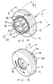
- a punching element 10 is shown with a hollow head portion 12 of larger transverse dimension D1, with a hollow shank portion 14 of smaller transverse dimension D2, which protrudes away from a side 16 of the head part 12, wherein an annular sheet metal bearing surface 18 is formed on said side 16 of the head part 12 and surrounding the shaft part 14.
- the stamping element 10 is provided with a plurality of ribs 20 on the outer circumference of the shaft portion 14, which extend in the axial direction (central longitudinal axis 22) along the shaft portion 14 of the sheet metal bearing surface 18 to close to the free end 24 of the shaft portion 14.
- D1 is - without limitation - about twice the size of D2.
- the ribs extend from the said side over the full length of the shaft part 14. However, this is not absolutely necessary, they could extend over at least 80% of the total length L of the shaft part, and they could, for example and without limitation, by an amount 0.1L from the front end 24 of the shaft part 14 to end and stop by an amount of 0.1L in front of the sheet metal bearing surface 18.
- the preferred construction is but out Fig. 1A can be seen, in which the longitudinal ribs in an axial annular groove 26 radially within the sheet metal bearing surface 18 come to an end, with material accumulations 28 are located between the longitudinal ribs and are also included in the axial annular groove 26.
- This design has the advantage that there are no features, except for the shaft part with the longitudinal ribs 20, in front of the sheet metal bearing surface 18, so that the sheet metal bearing surface can fit snugly on one side of a first sheet metal part.
- the ribs 20 are here distributed uniformly around the outer circumference of the shaft part 14. However, this is not mandatory.
- the head part 12 and the shaft part 14 are here hollow and a threaded cylinder 30 is formed both in the head part 12 and in the shaft part 14.
- the threaded cylinder 30 is provided with a threaded inlet 32 and with a threaded outlet 34.
- the stamping element could be formed such that on the other side of the head part, a stud shaft with external thread is formed (not shown).
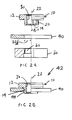
- the stamping element 10 is, as in the FIGS. 2A to 2E shown attached to a first sheet metal part 40 for forming a pre-assembly 42.
- the previously described stamping element with the free end is in accordance with Fig. 2A coming from above so far pressed into the pre-punched sheet metal part 40 that an end portion 44 of the shaft portion 14 protrudes from the sheet metal part 40.
- a die 50 which will be described in more detail later, some but not all of the longitudinal ribs 20 from the end portion 44 of the shaft portion 14 fully scraped away or partially and converted into material projections 52, ie sheared and compressed, the in FIGS. 2D and 2E can be seen.
- the material tabs 52 engage radially in the material of the sheet metal part 40 fully or partially, in such a way that the sheet metal part 40 is clamped between the lugs and the sheet metal bearing surface 18.
- the remaining non-scraped longitudinal ribs 20 are, as also from the FIGS. 2D and 2E visible, still available at the end part.
- the method for producing the pre-assembly component thus proceeds as follows:
- the first sheet-metal part 40 for example a ship as explained above, is first pre-punched with a hole diameter which essentially corresponds to the diameter D2 of the shaft part, ie with a radius D2 / 2, but may also be slightly smaller or larger.
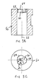
- the sheet metal part 40 is then supported on the passage 60 having a die 50 which in the Figs. 3A to 3C is shown.
- the passage 60 has at least first and second alternating portions 62 and 64, respectively, about its circumference, the first portions 62 having a radius D2 / 2 from the central longitudinal axis 22 of the piercing element 10 corresponding to the radius D2 / 2 of the shaft portion 14 ,
- the second regions 64 have a radius of the central longitudinal axis 22 of the stamping element 10, which corresponds to the radius Rr of the outer sides of the longitudinal ribs 20 from the central longitudinal axis 22 of the stamping element 10.
- the total number of the smaller regions 62 and the larger regions 34 is about half the total number of longitudinal ribs 20, so that the longitudinal ribs 20 are scraped away in pairs around the regions 62, while further alternate pairs of longitudinal ribs are aligned with the larger regions 64 and are not peeled off , A special orientation of the die or the stamping element is not required. Even if - due to an unfavorable orientation - an area 62 smaller radius with three longitudinal ribs, for example, it will scrape the middle longitudinal rib and the two adjacent longitudinal ribs 20 half scraping, which is not further catastrophic, since here too enough material tabs 52 and enough Longitudinal rib rests (full or partial) are present to ensure the required anti-twist protection.
- two adjacent longitudinal ribs 20 are thus transformed by means of the die 50 and, as in the next ribs in Circumferentially the die 50 has a recess (area 64), so that the longitudinal ribs 20 are not deformed here.
- the die 50 has a recess (area 64), so that the longitudinal ribs 20 are not deformed here.
- area 64 area 64
- no orientation in the direction of rotation is required, since only half of all ribs are affected.
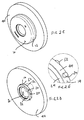
- FIGS. 4A and 4B The method for producing an assembly part 70 comprising the pre-assembly component 42 described above and a second sheet metal part 70 will now be described with reference to FIGS FIGS. 4A and 4B described.
- Fig. 4A the second non-pre-punched sheet metal part 70 supported on a second die 80.
- This has a central passage 82 with a diameter D2 corresponding to the basic diameter D2 of the end portion 44 of the shaft portion 14 of the stamping element 10 and an annular lug 84 arranged around the central passage 82.
- the end portion 44 By pressing the pre-assembly unit 42 with the front end 24 of the end portion 44 ahead against the side facing away from the die 80 side 86 of the second sheet metal part 70, the end portion 44 generates by means of the die 80 a hole 88 in the second sheet metal part and a punched slug 90, by the extended area 87 of the die 80 falls through and is disposed of.
- the annular nose 84 generates an annular recess 92 in the side facing away from the head part 12 94 of the second sheet metal part 70th around the end part 44 around.
- the annular recess 92 which is provided in the side facing away from the first sheet metal part 40 of the second sheet metal part 70, thus surrounds the end portion 44th
- the remaining longitudinal ribs 20 on the end portion 44 of the shaft portion 14 form furrows (not visible) in the side wall of the hole 88, which provide by the corresponding positive engagement with the longitudinal ribs for a good anti-rotation.
- This is increased or supplemented by the hole reveal, and the hole reveal also provides for a significant Auspresswiderstand.
- the annular recess 92 increases the hole reveal and can also lead to a small but highly effective further positive connection with the shank portion 14 in the region of its end portion 44, which further increases the Auspresswiderstand.
- the shaft part 14 is at least substantially not deformed at least in the region of the thread 30.
- the assembly part 100 is the assembly part 100 according to the Fig. 4B
- the first sheet metal part 40 could have a thickness in the range of 2.0 to 4 mm or larger, while the second sheet metal part may have a thickness of 0.6 to 1.8 mm These values should not be construed as limiting.
- stamping element As material for the stamping element come - without limitation - all materials in question, which are able to meet a fastener of strength class 8.8 or higher according to DIN standard.
Description
Die vorliegende Anmeldung betrifft ein Einstanzelement mit einem hohlen Kopfteil größerer Querabmessung, mit einem hohlen Schaftteil kleinerer Querabmessung, der von einer Seite des Kopfteils weg ragt, wobei eine ringförmige Blechanlagefläche auf der genannten Seite des Kopfteils ausgebildet ist und den Schaftteil umgibt, ein Vormontagebauteil bestehend aus dem Einstanzelement und zumindest einem Blechteil, ein Zusammenbauteil bestehend aus dem Vormontagebauteil und einem weiteren Blechteil sowie ein Verfahren zum Herstellen des Zusammenbauteils.The present application relates to a stamping element having a hollow head part of larger transverse dimension, with a hollow shank part of smaller transverse dimension, which protrudes away from a side of the head part, wherein an annular sheet metal bearing surface is formed on said side of the head part and surrounds the shaft part, consisting of a pre-assembly the stamping element and at least one sheet metal part, an assembly part consisting of the pre-assembly and a further sheet metal part and a method for producing the assembly part.
Ein Einstanzelement dieser Art ist aus der
Darüber hinaus ist ein Nietelement aus der
Ein weiteres Nietelement ist aus der
Keine der oben beschriebenen Elemente ist für die Anbringung an ein erstes und ein zweites Blechteil gedacht oder dafür ausgelegt. In der Praxis, vor allem auf dem Gebiet des Karosseriebaus, kommen immer wieder Anwendungen vor, bei denen ein Funktionselement an ein erstes und an ein zweites Blechteil angebracht werden muss, wobei die Anbringung an das erste Blechteil an einer Stelle in einer Fabrik erfolgen kann, während die Anbringung an das zweite Blechteil an einer anderen Stelle in der gleichen Fabrik oder in einer anderen Fabrik erfolgt. Häufig werden die ersten Blechteile mit angebrachten Funktionselementen lose in Kisten von einer Stelle zur anderen transportiert und sind deshalb Erschütterungen und gegebenenfalls rauer Handhabung ausgesetzt, die zu einer Lockerung des Funktionselements im ersten Blechteil oder gar zu einem Auseinanderfallen der beiden Teilen führen kann, so dass sie für die Anbringung am zweiten Blechteil nicht mehr tauglich sind oder nur mit größerem Aufwand verwendbar sind. Gerade bei der Serienfertigung stellt dies ein erhebliches Problem dar.None of the elements described above is intended or intended for attachment to a first and a second sheet metal part. In practice, especially in the field of bodywork, there are always applications in which a functional element must be attached to a first and a second sheet metal part, wherein the attachment to the first sheet metal part can take place at a location in a factory, while the attachment to the second sheet metal part takes place at another location in the same factory or in another factory. Frequently, the first sheet metal parts with attached functional elements are transported loosely in boxes from one place to another and are therefore exposed to vibration and possibly rough handling, which can lead to a loosening of the functional element in the first sheet metal part or even a falling apart of the two parts, so that they are no longer suitable for attachment to the second sheet metal part or can be used only with great effort. Especially in mass production, this represents a significant problem.
Ein Beispiel für ein solches Zusammenbauteil ist die Anbringung von Scharnieren an Türholmen von Fahrzeugkarosserien. Die Türholme sind üblicherweise aus einem relativ dünnen Blech gefertigt, insbesondere dann, wenn sie ein Teil der Außenhaut des Fahrzeugs sind. Es ist dann bekannt, Mutterelemente an einem sogenannten Schiff anzubringen, das durch ein weiteres im Querschnitt häufig eine flache gebogene U-Form aufweisendes dickeres Blechteil gebildet ist, das zur Versteifung an den Türholm von der Innenseite angeschweißt wird. Bei der Auslegung der Türscharniere und der Anbringung an einen Türholm muss stets bedacht werden, dass eine relativ schwere Person mit beispielsweise 150 Kg Körpergewicht sich an den Türrahmen beim Ein- und Aussteigen abstützen kann, wodurch erhebliche Hebelkräfte vom Türholm aufgenommen werden müssen, ohne dass sich dieser verformt.An example of such an assembly member is the attachment of hinges to door beams of vehicle bodies. The door beams are usually made of a relatively thin sheet metal, especially if they are part of the outer skin of the vehicle. It is then known to mount nut elements on a so-called ship, which is formed by another in cross-section often a flat curved U-shape exhibiting thicker sheet metal part, which is welded to the stiffening of the door spar from the inside. When designing the door hinges and attaching to a door spar, it must always be borne in mind that a relatively heavy person, for example, 150 kg body weight can be supported on the door frame when boarding and disembarking, so that considerable leverage must be absorbed by the door spar without this deformed.
Die
Es wird ein Einstanzelement bereitgestellet, das besonders für die Anbringung an erste und zweite Blechteile gedacht ist, wobei die Anbindung an das erste Blechteil einerseits sicher ist, so dass eine Lockerung des Elements des ersten Blechteils nicht zu befürchten ist, und die Anbringung an ein zweites Blechteil problemlos erreicht werden kann, ohne auf eine besondere Orientierung des Elements achten zu müssen.It is provided a stamping element, which is particularly intended for attachment to first and second sheet metal parts, the connection to the first sheet metal part on the one hand is safe, so that a loosening of the element of the first sheet metal part is not to be feared, and attachment to a second Sheet metal part can be easily achieved without having to pay attention to a special orientation of the element.
Die der vorliegenden Erfindung zugrundeliegende Aufgabe ist es, eine Vormontagebaueinheit bestehend aus dem Element und dem ersten Blechteil und ein fertiges Zusammenbauteil bestehend aus der Vormontagebaueinheit und einem zweiten Blechteil zu schaffen, die stabil und preisgünstig herstellbar sind, wie auch ein entsprechendes Herstellungsverfahren für das Zusammenbauteil. Zur Lösung dieser Aufgabe wird erfindungsgemäß ein Vormontagebauteil mit den in Anspruch 1 offenbarten Merkmalen vorgesehen.The object underlying the present invention is to provide a Vormontagebaueinheit consisting of the element and the first sheet metal part and a finished assembly part consisting of the Vormontagebaueinheit and a second sheet metal part, which are stable and inexpensive to produce, as well as a corresponding manufacturing method for the component assembly. To achieve this object, a pre-assembly with the features disclosed in claim 1 is provided according to the invention.
An dieser Stelle soll betont werden, dass, wenn hier von einem ersten Blechteil und einem zweiten Blechteil die Rede ist, ein solches Blechteil mehrlagig ausgebildet werden kann, wobei die mehreren Lagen eines Blechteils beispielsweise aneinander geschweißt oder verklebt sein können. Zum Beispiel kann das erste Blechteil aus zwei oder mehreren aneinander geschweißten Blechteilen bestehen und das zweite Blechteil ebenso.At this point, it should be emphasized that, if here of a first sheet metal part and a second sheet metal part is mentioned, such a sheet metal part can be formed multi-layer, wherein the plurality of layers of a sheet metal part, for example, welded to each other or can be glued. For example, the first sheet metal part may consist of two or more welded sheet metal parts and the second sheet metal part as well.
Insbesondere zeichnet sich das Einstanzelement dadurch aus, dass die Rippen sich von der ringförmigen Blechanlagefläche bis nahe an das freie Ende des Schaftteils erstrecken.In particular, the stamping element is characterized in that the ribs extend from the annular sheet metal bearing surface to close to the free end of the shaft part.
Wenn gesagt wird, dass sich die Rippen von der ringförmigen Blechanlagefläche bis nahe an das freie Ende des Schaftteils erstrecken, bedeutet dies, dass sie von der ringförmigen Blechanlagefläche oder nahe an der ringförmigen Blechanlagefläche sich über mindestens 80 % der gesamten Länge des Schaftteils erstrecken.When it is said that the ribs extend from the annular sheet bearing surface to near the free end of the shank portion, this means that they extend from the annular sheet bearing surface or close to the annular sheet bearing surface over at least 80% of the entire length of the shank portion.
Dabei werden die Rippen vorzugsweise gleichmäßig verteilt um den Außenumfang des Schaftteils angeordnet.The ribs are preferably arranged evenly distributed around the outer circumference of the shaft part.
Sowohl der Kopfteil als auch der Schaftteil sind vorzugsweise hohl ausgebildet, wobei ein Gewindezylinder im Kopfteil und im Schaftteil ausgebildet ist.Both the head part and the shaft part are preferably hollow, wherein a threaded cylinder is formed in the head part and in the shaft part.
Eine alternative Ausbildung des Einstanzelements ist dem Unteranspruch 5 zu entnehmen.An alternative embodiment of the stamping element can be found in the dependent claim 5.
Die erfindungsgemäße Vormontagebaueinheit umfasst zumindest ein erstes vorgelochtes Blechteil, in das zumindest ein Einstanzelement gemäß zumindest einer der vorstehenden Ausführungsformen mit seinem freien Ende voraus so weit im vorgelochten Blechteil eingepresst ist, dass ein Endteil des Schaftteils aus dem Blechteil herausragt und dass einige aber nicht alle der Längsrippen vom Endteil des Schaftteils voll oder teilweise weggeschabt und zu Materialnasen umgeformt sind, d.h. abgeschert und gestaucht wurden, wobei die Materialnasen radial in das Material des Blechteils voll oder teilweise eingreifen oder an dem Blechteil anliegen, wodurch das Blechteil zwischen den Nasen und der Blechanlagefläche eingeklemmt ist und die restlichen nicht weggeschabten Längsrippen noch am Endteil vorhanden sind.The pre-assembly according to the invention comprises at least a first pre-punched sheet metal part, in which at least one stamping element according to at least one of the preceding embodiments with its free end is pressed so far ahead in the pre-punched sheet metal part that an end portion of the shaft portion protrudes from the sheet metal part and that some but not all of Longitudinal ribs are scraped away from the end part of the shaft part fully or partially and formed into material noses, ie sheared and compressed, wherein the material lugs radially engage in the material of the sheet metal part fully or partially or bear against the sheet metal part, whereby the sheet metal part is clamped between the lugs and the sheet metal bearing surface and the remaining non-scraped longitudinal ribs are still present at the end part.
Durch die Materialnasen wird somit das Einstanzelement formschlüssig und verdrehsicher am ersten Blechteil angebracht, und zwar derart, dass eine Verbindung entsteht, bei der eine Lockerung des Elements im ersten Blechteil oder gar eine unerwünschte Trennung der beiden Bauteile nicht zu befürchten ist. Wie später näher erläutert wird, muss bei der Herstellung der Vormontagebaueinheit weder auf eine besondere Drehposition des Elements noch auf eine entsprechende Drehposition der verwendeten Matrize geachtet werden.By the material lugs thus the stamping element is positively and rotationally secured to the first sheet metal part, in such a way that a connection is formed in which a loosening of the element in the first sheet metal part or even an unwanted separation of the two components is not to be feared. As will be explained later, care must be taken in the preparation of Vormontagebaueinheit neither to a particular rotational position of the element nor to a corresponding rotational position of the die used.
Diese Vormontagebaueinheit kann dann mit einem zweiten nicht vorgelochten Blechteil zu einem erfindungsgemäßen Zusammenbauteil komplementiert werden, in dem das Endteil selbststanzend in das zweite Blechteil mit Ausbildung eines Loches im zweiten Blechteil eingebracht wird, wodurch die restlichen nicht weggeschabten Längsrippen, die noch am Endteil vorhanden sind, formschlüssig in Furchen des Lochrandes eingreifen, die durch das Einpressen der Vormontagebaueinheit entstehen.This Vormontagebaueinheit can then be complemented with a second non-pre-punched sheet metal part to a component assembly according to the invention, in which the end part is self-piercing introduced into the second sheet metal part with formation of a hole in the second sheet metal part, whereby the remaining non-scraped longitudinal ribs, which are still present at the end part, interlock positively in furrows of the hole edge, resulting from the pressing of the Vormontagebaueinheit.
Somit wird auch die Vormontagebaueinheit verdrehsicher und - bedingt durch die hohe Lochlaibung - auch auspresssicher am zweiten Blechteil angebracht.Thus, the pre-assembly unit is secured against rotation and - due to the high hole reveal - also auspresssicher attached to the second sheet metal part.
Besonders günstig ist es, wenn eine Ringvertiefung in der dem ersten Blechteil abgewandten Seite des zweiten Blechteils vorgesehen ist, die das Endteil umgibt.It is particularly favorable if an annular recess is provided in the side of the second sheet metal part facing away from the first sheet metal part, which surrounds the end part.
Hierdurch wird die Lochlaibung erhöht, wodurch auch der Auspresswiderstand erhöht wird.As a result, the hole reveal is increased, whereby the Auspresswiderstand is increased.
Bei der Herstellung des Zusammenbauteils wird das Schaftteil mindestens im Bereich des Gewindes zumindest im Wesentlichen nicht verformt.In the production of the assembly part, the shaft part is at least substantially not deformed at least in the region of the thread.
Das erfindungsgemäße Verfahren zum Herstellen eines Vormontagebauteils bestehend aus einem Blechteil und einem Einstanzelement der oben beschriebenen und im Anspruch 1 beanspruchten Art wird so durchgeführt, dass das Blechteil vorgelocht wird mit einem Lochdurchmesser, der dem Durchmesser des Schaftteils entspricht, dass das Blechteil auf einer eine Passage aufweisende Matrize abgestützt wird, die mindestens erste und zweite abwechselnde Bereiche um die Passage herum aufweist, wobei die ersten Bereiche einen Radius von der mittleren Längsachse des Einstanzelements aufweisen, der dem Radius des Schaftteils entspricht, und die zweiten Bereiche einen Radius von der mittleren Längsachse des Einstanzelements aufweisen, der dem Radius der Außenseiten der Längsrippen von der mittleren Längsachse des Einstanzelements entspricht.The inventive method for producing a pre-assembly consisting of a sheet metal part and a stamping element of the type described above and claimed in claim 1 is carried out so that the sheet metal part is pre-perforated with a hole diameter corresponding to the diameter of the shaft portion that the sheet metal part on a a passage supporting the die having at least first and second alternating regions around the passage, the first regions having a radius from the central longitudinal axis of the piercing element corresponding to the radius of the shaft part, and the second regions being radiused from the central longitudinal axis of the stem Stamping element, which corresponds to the radius of the outer sides of the longitudinal ribs of the central longitudinal axis of the stamping element.
Hierdurch werden einige, aber nicht alle der Längsrippen zu Materialnasen der oben beschriebenen Art umgeformt. Dabei spielt es keine Rolle, ob die ersten Bereiche eine oder zwei Längsrippen voll oder teilwiese treffen, da die verbleibenden Längsrippen am Endteil, sei es voll oder teilweise abgeschabte Längsrippen, für die verdrehsichere Anbringung an das zweite Blechteil ausreichen. Es soll nur eine unterschiedliche Zahl von Längsrippen und erste Bereiche und/oder eine unterschiedliche Winkelerstreckung der Längsrippen und der ersten Bereiche geben, damit nur einige der Längsrippen oder Teile davon von den ersten Bereichen weggeschabt werden. Üblicherweise werden weniger erste Bereiche als Längsrippen vorgesehen.As a result, some, but not all of the longitudinal ribs are formed into material noses of the type described above. It does not matter if the first regions meet one or two longitudinal ribs fully or partially, since the remaining longitudinal ribs on the end part, be it full or partially scraped longitudinal ribs, suffice for the rotationally secure attachment to the second sheet metal part. There should only be a different number of longitudinal ribs and first regions and / or a different angular extent of the longitudinal ribs and the first regions, so that only some of the longitudinal ribs or parts thereof are scraped away from the first regions. Usually less first areas are provided as longitudinal ribs.
Ferner umfasst die vorliegende Erfindung ein Verfahren zum Herstellen eines Zusammenbauteils bestehend aus dem oben beschriebenen Vormontagebauteil und einem zweiten Blechteil, wobei das zweite nicht vorgelochte Blechteil auf einer Matrize abgestützt wird mit einer mittleren Passage mit einem Durchmesser entsprechend dem Grunddurchmesser des Endteils des Schaftteils des Einstanzelements und mit einer um die mittlere Passage herum angeordneten Ringnase, wobei durch Drücken der Vormontageeinheit mit dem Stirnende des Endteils voran gegen die der Matrize abgewandten Seite des zweiten Blechteils das Endteil mit Hilfe der Matrize ein Loch im zweiten Blechteil und einen Stanzbutzen erzeugt, und die Ringnase eine Ringvertiefung in der dem Kopfteil abgewandten Seite des zweiten Blechteils um das Endteil herum erzeugt.Furthermore, the present invention comprises a method for producing an assembly part consisting of the above-described pre-assembly and a second sheet metal part, wherein the second non-pre-punched sheet metal part is supported on a die with a central passage having a diameter corresponding to the base diameter of the end part of the shank part of the stamping element and with an arranged around the central passage around ring nose, wherein by pressing the pre-assembly with the front end of the end portion against the side facing away from the female side of the second sheet metal part, the end part using the die creates a hole in the second sheet metal part and a punched neck, and the ring nose a Ring depression in the side facing away from the head part of the second sheet metal part generated around the end part.
Auch hier muss nicht auf eine besondere Orientierung der Vormontagebaueinheit oder der zweiten Matrize geachtet werden, da die verbleibenden Längsrippen oder Längsrippenteile am Endteil des Schaftteils nicht in Berührung mit der zweiten Matrize gelangen, zumal im installierten Zustand das freie Stirnende des Schaftteils nicht über die dem Kopfteil abgewandten Seite des zweiten Blechteils hinausragt, sondern vorzugsweise gegenüber dieser geringfügig zurückversetzt ist, beispielsweise um 0,02 mm. Die Erfindung wird nachfolgend anhand eines Ausführungsbeispiels und unter Bezugnahme auf die Zeichnungen näher erläutert, in denen zeigen:
- Fig. 1A - 1B
- perspektivische Darstellungen eines Einstanzelements, aus denen die Formgebung des Elements von beiden Stirnseiten ersichtlich ist,
- Fig. 2A - 2E
- Darstellungen, wie das Einstanzelement in ein erstes Blechteil eingebracht wird und wie die hierdurch gefertigte erfindungsgemäße Vormontageeinheit aussieht, wobei
Fig. 2A das Einstanzelement oberhalb des vorgelochten ersten Blechteils mit darunterliegender Matrize zeigt, dieFig. 2B die fertige Vormontagebaueinheit in teilweise in Längsrichtung geschnittenem Zustand zeigt, dieFig. 2C und 2D perspektivischer Darstellungen der fertigen Vormontagebaueinheit gemäßFig. 2B von beiden Seiten zeigen und dieFig. 2E eine vergrößerte Darstellung des eingekreisten Bereichs derFig. 2D zeigt, - Fig. 3A -3C
- die in der
Fig. 2A verwendete Matrize in einer perspektivischen Darstellung (Fig. 3A ), in einer in Längsrichtung geschnittenen Ansicht (Fig. 3B ) und in einer Stimansicht (Fig. 3C ), - Fig. 4A -4B
- die Anbringung der erfindungsgemäßen Vormontagebaueinheit gemäß
Fig. 2B bis 2E an ein zweites Bauteil mit Hilfe einer zweiten Matrize (Fig. 4A ) zur Bildung eines erfindungsgemäßen Zusammenbauteils (Fig. 4B ).
- Fig. 1A - 1B
- perspective views of a stamping element showing the shape of the element from both end faces,
- Fig. 2A - 2E
- Representations of how the stamping element is introduced into a first sheet metal part and how the pre-assembly according to the invention produced thereby looks, wherein
Fig. 2A shows the stamping element above the pre-punched first sheet metal part with underlying die, theFig. 2B shows the finished pre-assembly in partially cut in the longitudinal direction state, theFig. 2C and 2D perspective views of the finished preassembly according toFig. 2B show from both sides and theFig. 2E an enlarged view of the circled area ofFig. 2D shows, - Fig. 3A-3C
- the in the
Fig. 2A used template in a perspective view (Fig. 3A ), in a longitudinal sectional view (Fig. 3B ) and in an end view (Fig. 3C ) - Fig. 4A-4B
- the attachment of the pre-assembly according to the invention according to
Fig. 2B to 2E to a second component by means of a second die (Fig. 4A ) for forming a component according to the invention (Fig. 4B ).
Bezug nehmend auf die
Hier erstrecken sich die Rippen ausgehend von der genannten Seite über die volle Länge des Schaftteils 14. Dies ist allerdings nicht zwingend erforderlich, sie könnten sich über mindestens 80 % der gesamten Länge L des Schaftteils erstrecken, und sie könnten beispielsweise und ohne Einschränkung um einen Betrag 0,1L vom Stirnende 24 des Schaftteils 14 zu Ende gehen und um einen Betrag von 0,1L vor der Blechanlagefläche 18 aufhören. Die bevorzugte Konstruktion ist aber aus
Die Rippen 20 sind hier gleichmäßig um den Außenumfang des Schaftteils 14 verteilt angeordnet. Dies ist allerdings nicht zwingend erforderlich.The
Der Kopfteil 12 und der Schaftteil 14 sind hier hohl ausgebildet und ein Gewindezylinder 30 ist sowohl im Kopfteil 12 als auch und im Schaftteil 14 ausgebildet. Der Gewindezylinder 30 ist mit einem Gewindeeinlauf 32 und mit einem Gewindeauslauf 34 versehen.The
Alternativ hierzu könnte das Einstanzelement derart ausgebildet werden, dass auf der anderen Seite des Kopfteils ein Bolzenschaft mit Außengewinde ausgebildet ist (nicht gezeigt).Alternatively, the stamping element could be formed such that on the other side of the head part, a stud shaft with external thread is formed (not shown).
Das Einstanzelement 10 wird, wie in den
Das Verfahren zum Herstellen des Vormontagebauteils läuft somit wie folgt ab: Das erste Blechteil 40, beispielsweise ein Schiff wie oben erläutert, wird zunächst vorgelocht mit einem Lochdurchmesser der im Wesentlichen dem Durchmesser D2 des Schaftteils entspricht, d.h. mit einem Radius D2/2, der aber auch geringfügig kleiner oder größer sein kann. Das Blechteil 40 wird anschließend auf der eine Passage 60 aufweisende Matrize 50 abgestützt, die in den
Die Gesamtanzahl der kleineren Bereiche 62 und der größeren Bereiche 34 entspricht etwa der Hälfte der Gesamtzahl von Längsrippen 20, so dass die Längsrippen 20 paarweise um die Bereiche 62 weggeschabt werden, während weitere abwechselnde Paare von Längsrippen mit den größeren Bereichen 64 fluchten und nicht abgeschält werden. Eine besondere Orientierung der Matrize oder des Einstanzelements ist nicht erforderlich. Selbst wenn - aufgrund einer ungünstigen Orientierung - ein Bereich 62 kleineren Radius mit beispielsweise drei Längsrippen fluchten soll, wird sie die mittlere Längsrippe voll und die zwei benachbarten Längsrippen 20 zur Hälfte wegschaben, was nicht weiter tragisch ist, da auch hier genügend Materialnasen 52 und genügend Längsrippenreste (voll oder teilweise) vorliegen, um die erforderliche Verdrehsicherung sicherzustellen.The total number of the
Bei dieser Ausführung werden somit mittels der Matrize 50 jeweils zwei benachbarte Längsrippen 20 umformt und, da bei den nächsten Rippen in Umfangsrichtung die Matrize 50 eine Aussparung (Bereich 64) aufweist, so dass die Längsrippen 20 hier nicht umgeformt werden. Für diese Anordnung ist keine Orientierung in Drehrichtung erforderlich, da nur jeweils die Hälfte aller Rippen betroffen ist. Selbst wenn die Matrize zufällig so orientiert ist, dass der Übergang von Umformen auf Nicht-Umformen im Bereich einer Rippe zu liegen kommt, entstehen halt zwei halb umgeformte und eine voll umgeformte Rippe.In this embodiment, two adjacent
Es ist allerdings keinesfalls erforderlich, ein bestimmtes Verhältnis zwischen Gesamtzahl der Bereiche 62 oder 64 zu der Gesamtzahl der Längsrippen einzuhalten, oder gleiche Winkelerstreckungen der Bereiche 62, 64 zu wählen. Es muss nur darauf geachtet werden, dass eine ausreichende Zahl von Materialnasen 52 und eine ausreichende Zahl von verbleibenden Längsrippen oder Längsrippenteile am Endteil 44 verbleiben, um die erwünschte Verdrehsicherung zu gewährleisten.However, it is by no means necessary to maintain a certain ratio between the total number of
Das Verfahren zum Herstellen eines Zusammenbauteils 70 bestehend aus dem oben beschriebenen Vormontagebauteil 42 und einem zweiten Blechteil 70 wird nunmehr anhand der
Die noch verbleibenden Längsrippen 20 am Endteil 44 des Schaftteils 14 bilden Furchen (nicht ersichtlich) in der Seitenwand des Loches 88, die durch den entsprechenden Formschluss mit den Längsrippen für eine gute Verdrehsicherung sorgen. Dies wird durch die Lochlaibung erhöht bzw. ergänzt, und die Lochlaibung sorgt auch für einen erheblichen Auspresswiderstand. Die Ringvertiefung 92 erhöht die Lochlaibung und kann auch zu einem kleinen, aber hochwirksamen weiteren Formschluss mit dem Schaftteil 14 im Bereich seines Endteils 44 führen, der den Auspresswiderstand weiter erhöht. Das Schaftteil 14 ist aber mindestens im Bereich des Gewindes 30 zumindest im Wesentlichen nicht verformt.The remaining
Das Ergebnis dieses Verfahrens ist das Zusammenbauteil 100 gemäß der
Als Material für das Einstanzelement kommen - ohne Einschränkung - alle Materialien in Frage, die imstande sind, ein Verbindungselement der Festigkeitsklasse 8.8 oder hoher gemäß DIN-Norm zu erfüllen.As material for the stamping element come - without limitation - all materials in question, which are able to meet a fastener of strength class 8.8 or higher according to DIN standard.
Claims (10)
- A pre-installation component which includes at least one sheet metal part (40) into which at least one punch-in element (10) has been pressed, the punch-in element having a hollow head part (12) of larger transverse dimension (D1) with a hollow shaft part (14) of smaller transverse dimension (D2) which projects away from one side (16) of the head part (12), wherein a ring-like sheet metal contact surface (18) is formed at the said side (16) of the head part (12) and surrounds the shaft part (14), and with a plurality of ribs (20) at the outer periphery of the shaft part (14) which extend in the axial direction (22) along the shaft part (14) from the sheet metal contact surface (18) to close to the free end (24) of the shaft part (14), the punch-in element having been pressed with its front end (24) to the fore into the pre-pierced sheet metal part (40), to such an extent that an end part (44) of the shaft part (14) projects out of the sheet metal part, characterized in that some but not all of the longitudinal ribs (20) are fully or partly displaced from the end part (44) of the shaft part (14) and reshaped into material noses (52), i.e. are sheared and compressed, with the material noses (52) engaging radially into the material of the sheet metal part (40) fully or partly or contacting the sheet metal part and the sheet metal part (40) being clamped between the noses (52) and the sheet metal contact surface (18) and wherein the remaining non-displaced longitudinal ribs (20) are still present at the end part (44).
- A pre-installation component in accordance with claim 1,
characterized in that
the non-displaced ribs (20) of the punch-in element extend, starting from the said side (16), over at least 80 % of the total length of the shaft part. - A pre-installation component in accordance with claim 1 or claim 2,
characterized in that
the ribs (20) are uniformly distributed around the outer periphery of the shaft part (14). - A pre-installation component in accordance with at least one of the preceding claims,
characterized in that
both the head part (12) and also the shaft part (14) of the punch-in element are of hollow design and in that a thread cylinder (30) is formed in the head part and in the shaft part. - A pre-installation component in accordance with any one of the claims 1 to 3,
characterized in that
a bolt shaft with an external thread is formed at the other side of the head part of the punch-in element. - A component assembly comprising the pre-installation component (42) in accordance with at least one of the claims 1 to 5 and a second sheet metal part (70),
characterized in that
the end part (44) is introduced in a self-piercing manner into the second sheet metal part (70) with the formation of a hole (88) in the second sheet metal part, whereby the remaining non-displaced longitudinal ribs (20) which are still present at the end part (44) engage in form-fitted manner in grooves of the hole rim. - A component assembly in accordance with claim 6,
characterized in that
a ring recess (92) is provided in the side (86) of the second sheet metal part (70) remote from the first sheet metal part (40) and surrounds the end part (44). - A component assembly in accordance with one of the claims 6 or 7,
characterized in that
the shaft part (14) is at least substantially not deformed in the area of the thread (30). - A method for the manufacture of a pre-installation component (42) consisting of a sheet metal part (40) and a punch-in element (10) having a hollow head part (12) of larger transverse dimension (D1) and a hollow shaft part (14) of smaller transverse dimension (D2) which projects away from one side (16) of the head part, wherein a ring-like sheet metal contact surface (18) is formed at the said side of the head part (12) and surrounds the shaft part, with a plurality of ribs (20) at the outer periphery of the shaft part (14) which extend in an axial direction (22) along the shaft part from the sheet metal contact surface (18) up to close to the free end (24) of the shaft part (14), wherein the sheet metal part is pre-pierced with a hole diameter D2 which corresponds to the diameter D2 of the shaft part; in that the sheet metal part is supported on a die button (50) having a passage (60), the die button having at least first and second alternating regions (62, 64) around the passage (60), with the first regions (62) having a radius (R) from the central longitudinal axis (22) of the punch-in element (10) which corresponds to the radius (D2/2) of the shaft part (14) and the second regions having a radius (Rr) from the central longitudinal axis (22) of the punch-in element (10) which corresponds to the radius (Rr) of the outer sides of the longitudinal ribs (20) from the central longitudinal axis (22) of the punch-in element (10).
- A method for the manufacture of a component assembly (100) consisting of the pre-installation component (42) manufactured in accordance with claim 9 and a second sheet metal part (70), wherein the second not pre-pierced sheet metal part is supported on a die button (80) having a central passage (82) with a diameter (D2) corresponding to a base diameter (D2) of the end part (44) of the shaft part (14) of the punch-in element (10) and with a ring nose (84) arranged around the central passage, wherein, by pressing the pre-installation unit (42) with the free end (24) of the end part (44) to the fore against the side of the second sheet metal part (70) remote from the die button (80), the end part (44) generates a hole in the second sheet metal part and a piercing slug (90) with the aid of the die button (80) and the ring nose (84) forms a ring recess (92) in the side (86) of the second sheet metal part (70) remote from the head part (12) around the end part (44).
Applications Claiming Priority (1)
| Application Number | Priority Date | Filing Date | Title |
|---|---|---|---|
| DE102012003972A DE102012003972A1 (en) | 2012-02-29 | 2012-02-29 | Stamping element, pre-assembly, assembly part and method |
Publications (2)
| Publication Number | Publication Date |
|---|---|
| EP2634437A1 EP2634437A1 (en) | 2013-09-04 |
| EP2634437B1 true EP2634437B1 (en) | 2015-11-25 |
Family
ID=47748507
Family Applications (1)
| Application Number | Title | Priority Date | Filing Date |
|---|---|---|---|
| EP13156240.7A Active EP2634437B1 (en) | 2012-02-29 | 2013-02-21 | Punching element, preassembly component, assembly component and method |
Country Status (6)
| Country | Link |
|---|---|
| US (1) | US8839486B2 (en) |
| EP (1) | EP2634437B1 (en) |
| CN (1) | CN103291718B (en) |
| DE (1) | DE102012003972A1 (en) |
| ES (1) | ES2556836T3 (en) |
| RU (1) | RU2013108889A (en) |
Families Citing this family (10)
| Publication number | Priority date | Publication date | Assignee | Title |
|---|---|---|---|---|
| HUE043176T2 (en) * | 2006-12-28 | 2019-08-28 | Woodwelding Ag | Method for anchoring a joining element in an object and joining element to be used in the method |
| DE102013217633A1 (en) * | 2013-09-04 | 2015-03-05 | Profil Verbindungstechnik Gmbh & Co. Kg | Punch rivet and method of attaching individual components to each other, of which at least one component is formed by a workpiece made of composite material |
| DE102013217632A1 (en) | 2013-09-04 | 2015-03-05 | Profil Verbindungstechnik Gmbh & Co. Kg | Punch rivet and methods and apparatus for attaching individual components to each other, of which at least one component is formed by a workpiece made of composite material |
| DE102013218548A1 (en) | 2013-09-16 | 2015-03-19 | Profil Verbindungstechnik Gmbh & Co. Kg | Punch and method for punching a workpiece, which is present as a foam material and / or as a sandwich material, and method for producing the punch |
| DE102014104571A1 (en) * | 2014-04-01 | 2015-10-01 | Profil Verbindungstechnik Gmbh & Co. Kg | Self-piercing functional element and an assembly part consisting of the functional element and a sheet metal part |
| CN105986712A (en) * | 2015-02-28 | 2016-10-05 | 福特环球技术公司 | Vehicle hinge assembly and operating method thereof |
| DE102016104187A1 (en) * | 2016-03-08 | 2017-09-14 | Profil Verbindungstechnik Gmbh & Co. Kg | functional element |
| US10969037B2 (en) * | 2016-12-08 | 2021-04-06 | Hellermanntyton Corporation | Protective bundle routing grommet for wide range panel thickness |
| CN108311627A (en) * | 2017-01-16 | 2018-07-24 | 泛亚汽车技术中心有限公司 | Puncture steel nail and its installation mold certainly for connecting metallic plate |
| USD1005823S1 (en) * | 2020-11-09 | 2023-11-28 | Matthew WELLS | Grommet |
Family Cites Families (18)
| Publication number | Priority date | Publication date | Assignee | Title |
|---|---|---|---|---|
| GB1004562A (en) * | 1962-03-02 | 1965-09-15 | Walsh John & Co Inserts Ltd | Improvements in fasteners or bushes for anchoring in sheet material or the like |
| US5309618A (en) * | 1980-02-02 | 1994-05-10 | Profil Verbindungstechnik Gmbh & Co., Kg | Method of attaching a female fastener assembly to a panel |
| US5564873A (en) * | 1980-02-02 | 1996-10-15 | Multifastener Corporation | Self-attaching fastening element and method of attachment |
| US4525912A (en) * | 1983-05-09 | 1985-07-02 | Kabushiki Kaisha Aoyama Seisakusho | Pierce nut and a back-up die used in combination therewith |
| JPH01158206A (en) * | 1987-12-15 | 1989-06-21 | Jidosha Kiki Co Ltd | Connecting structure of mounting plate and bolt |
| DE4410475A1 (en) * | 1994-03-25 | 1995-09-28 | Profil Verbindungstechnik Gmbh | Rivetable element, assembly part with a rivetable element as well as rivet die and method for producing the assembly part |
| US5528812A (en) * | 1991-10-31 | 1996-06-25 | Profil-Verbindungstechnik Gmbh & Co. Kg | Method of attaching a fastener to a plurality of panels |
| US5445483A (en) * | 1993-08-23 | 1995-08-29 | Emhart Inc. | Female clinch fastener with cold-formed locking flange and associated installation method |
| DE19710246A1 (en) * | 1997-03-12 | 1998-09-17 | Profil Verbindungstechnik Gmbh | Element and method for inserting the element into a plate-shaped component |
| DE10119505A1 (en) * | 2001-04-20 | 2002-10-24 | Profil Verbindungstechnik Gmbh | Functional part has main body with annular flange leading into cylindrical rivet part and in-between conical surface, sheet metal part and locking part |
| JP2005226788A (en) * | 2004-02-16 | 2005-08-25 | Shinjo Mfg Co Ltd | Pierce nut |
| WO2006119401A2 (en) * | 2005-05-03 | 2006-11-09 | Whitesell International Corporation | Splined fastener |
| DE102006062073A1 (en) * | 2006-01-05 | 2007-07-12 | Profil Verbindungstechnik Gmbh & Co. Kg | Functional element e.g. bolt element for component assembly, has features of shape provided at rivet portion for co-movement of sheet metal portion during formation of rivet bead |
| RU2418206C2 (en) * | 2006-01-05 | 2011-05-10 | Профиль-Фербиндунгстехник Гмбх Унд Ко. Кг | Fastening element, subassembly, made of fastening element and sheet metal parts, and also method to fix fastening element onto sheet metal parts |
| DE102006002559A1 (en) | 2006-01-10 | 2007-07-12 | Swg Schraubenwerk Gaisbach Gmbh | countersunk |
| DE102007034987A1 (en) * | 2007-07-26 | 2009-01-29 | Profil Verbindungstechnik Gmbh & Co. Kg | Press-in element for pressing into a non-perforated or perforated component and method for producing the press-in element |
| DE102008052383A1 (en) | 2008-10-20 | 2010-04-22 | Profil Verbindungstechnik Gmbh & Co. Kg | Assembly part consisting of a fastener and a sheet metal part and a method for producing such a component assembly |
| DE102009042336A1 (en) | 2009-09-21 | 2011-03-24 | Profil Verbindungstechnik Gmbh & Co. Kg | Self-piercing hollow press-fit, assembly part consisting of a press-in element and a sheet metal part and a method for producing a self-piercing press-in nut and for attaching a self-piercing press-in nut |
-
2012
- 2012-02-29 DE DE102012003972A patent/DE102012003972A1/en not_active Withdrawn
-
2013
- 2013-02-21 EP EP13156240.7A patent/EP2634437B1/en active Active
- 2013-02-21 ES ES13156240.7T patent/ES2556836T3/en active Active
- 2013-02-27 US US13/779,726 patent/US8839486B2/en active Active
- 2013-02-27 RU RU2013108889/12A patent/RU2013108889A/en not_active Application Discontinuation
- 2013-02-28 CN CN201310062816.2A patent/CN103291718B/en active Active
Also Published As
| Publication number | Publication date |
|---|---|
| US20130223923A1 (en) | 2013-08-29 |
| CN103291718A (en) | 2013-09-11 |
| EP2634437A1 (en) | 2013-09-04 |
| US8839486B2 (en) | 2014-09-23 |
| CN103291718B (en) | 2016-12-28 |
| ES2556836T3 (en) | 2016-01-20 |
| DE102012003972A1 (en) | 2013-08-29 |
| RU2013108889A (en) | 2014-09-10 |
Similar Documents
| Publication | Publication Date | Title |
|---|---|---|
| EP2634437B1 (en) | Punching element, preassembly component, assembly component and method | |
| EP1806509B1 (en) | Functional element, assembly consisting of the functional element and a plate as well as procedure for the attachment of a functional element | |
| EP1674741B1 (en) | Element mountable in a piece of sheet metal by means of riveting, assembly and method for the manufacture of the assembly | |
| EP2292940B1 (en) | Self-stamping nut element and assembly component comprising the nut element and a sheet metal section | |
| EP1419319B2 (en) | Self-piercing fixing element that can be press-fitted to sheet metal in a torsion and expulsion-proof manner | |
| EP2177776B1 (en) | Assembly composed of an attachment element and a piece of sheet metal and a method for producing such an assembly | |
| DE3247555C2 (en) | Self-piercing mother | |
| EP2479442B1 (en) | Function element in the form of a press element | |
| EP2302234B1 (en) | Self-stamping hollow force fitting element, assembly component comprising a force fitting element and a sheet metal section and method for producing self-stamping force fitting nut and attaching same | |
| EP0667936A1 (en) | Insert for use as a connection element for joints designed to be secure against rotation and insert ejection. | |
| EP2412991B1 (en) | Self-stamping nut element and assembly component comprising the nut element and a sheet metal section | |
| EP1690013B1 (en) | Functional element, assembling component consisting of the functional element combined with a metal sheet, method for producing the assembling component and method for producing the functional element | |
| EP3158208B1 (en) | Component connection | |
| EP0957273B1 (en) | Fastening element and method for manufacturing the same | |
| EP0807025B1 (en) | Vehicle wheel and method of producing the same | |
| EP1101957B1 (en) | Assembly washer for a vehicle component | |
| EP1003243B1 (en) | Process for manufacturing an electrical connection to a metal sheet and mounting assembly | |
| EP2141370A1 (en) | Fastening element | |
| EP3877105B1 (en) | Fastening unit | |
| EP3705740B1 (en) | Screw connection and method for preventing the loosening of the screw connection | |
| EP3564545B1 (en) | Assembly composed of a component and an element with a head and a collar mounted on one side of the head and method of manufacture | |
| EP3936730A1 (en) | Function element | |
| DE19950719B4 (en) | Working method for producing a riveted joint and rivet, riveting tool and application thereof | |
| DE102019110635A1 (en) | Assembly part consisting of a component and an element with a head part and a collar arranged on one side of the head part and production method | |
| EP1529970B1 (en) | Washer and fastener |
Legal Events
| Date | Code | Title | Description |
|---|---|---|---|
| PUAI | Public reference made under article 153(3) epc to a published international application that has entered the european phase |
Free format text: ORIGINAL CODE: 0009012 |
|
| AK | Designated contracting states |
Kind code of ref document: A1 Designated state(s): AL AT BE BG CH CY CZ DE DK EE ES FI FR GB GR HR HU IE IS IT LI LT LU LV MC MK MT NL NO PL PT RO RS SE SI SK SM TR |
|
| AX | Request for extension of the european patent |
Extension state: BA ME |
|
| 17P | Request for examination filed |
Effective date: 20131129 |
|
| RBV | Designated contracting states (corrected) |
Designated state(s): AL AT BE BG CH CY CZ DE DK EE ES FI FR GB GR HR HU IE IS IT LI LT LU LV MC MK MT NL NO PL PT RO RS SE SI SK SM TR |
|
| GRAP | Despatch of communication of intention to grant a patent |
Free format text: ORIGINAL CODE: EPIDOSNIGR1 |
|
| INTG | Intention to grant announced |
Effective date: 20150526 |
|
| GRAS | Grant fee paid |
Free format text: ORIGINAL CODE: EPIDOSNIGR3 |
|
| GRAA | (expected) grant |
Free format text: ORIGINAL CODE: 0009210 |
|
| AK | Designated contracting states |
Kind code of ref document: B1 Designated state(s): AL AT BE BG CH CY CZ DE DK EE ES FI FR GB GR HR HU IE IS IT LI LT LU LV MC MK MT NL NO PL PT RO RS SE SI SK SM TR |
|
| REG | Reference to a national code |
Ref country code: GB Ref legal event code: FG4D Free format text: NOT ENGLISH |
|
| REG | Reference to a national code |
Ref country code: CH Ref legal event code: EP |
|
| REG | Reference to a national code |
Ref country code: AT Ref legal event code: REF Ref document number: 762779 Country of ref document: AT Kind code of ref document: T Effective date: 20151215 |
|
| REG | Reference to a national code |
Ref country code: IE Ref legal event code: FG4D Free format text: LANGUAGE OF EP DOCUMENT: GERMAN |
|
| REG | Reference to a national code |
Ref country code: DE Ref legal event code: R096 Ref document number: 502013001531 Country of ref document: DE |
|
| REG | Reference to a national code |
Ref country code: ES Ref legal event code: FG2A Ref document number: 2556836 Country of ref document: ES Kind code of ref document: T3 Effective date: 20160120 |
|
| REG | Reference to a national code |
Ref country code: FR Ref legal event code: PLFP Year of fee payment: 4 |
|
| REG | Reference to a national code |
Ref country code: LT Ref legal event code: MG4D |
|
| PG25 | Lapsed in a contracting state [announced via postgrant information from national office to epo] |
Ref country code: NO Free format text: LAPSE BECAUSE OF FAILURE TO SUBMIT A TRANSLATION OF THE DESCRIPTION OR TO PAY THE FEE WITHIN THE PRESCRIBED TIME-LIMIT Effective date: 20160225 Ref country code: IS Free format text: LAPSE BECAUSE OF FAILURE TO SUBMIT A TRANSLATION OF THE DESCRIPTION OR TO PAY THE FEE WITHIN THE PRESCRIBED TIME-LIMIT Effective date: 20160325 Ref country code: LT Free format text: LAPSE BECAUSE OF FAILURE TO SUBMIT A TRANSLATION OF THE DESCRIPTION OR TO PAY THE FEE WITHIN THE PRESCRIBED TIME-LIMIT Effective date: 20151125 Ref country code: NL Free format text: LAPSE BECAUSE OF FAILURE TO SUBMIT A TRANSLATION OF THE DESCRIPTION OR TO PAY THE FEE WITHIN THE PRESCRIBED TIME-LIMIT Effective date: 20151125 Ref country code: HR Free format text: LAPSE BECAUSE OF FAILURE TO SUBMIT A TRANSLATION OF THE DESCRIPTION OR TO PAY THE FEE WITHIN THE PRESCRIBED TIME-LIMIT Effective date: 20151125 |
|
| PG25 | Lapsed in a contracting state [announced via postgrant information from national office to epo] |
Ref country code: RS Free format text: LAPSE BECAUSE OF FAILURE TO SUBMIT A TRANSLATION OF THE DESCRIPTION OR TO PAY THE FEE WITHIN THE PRESCRIBED TIME-LIMIT Effective date: 20151125 Ref country code: LV Free format text: LAPSE BECAUSE OF FAILURE TO SUBMIT A TRANSLATION OF THE DESCRIPTION OR TO PAY THE FEE WITHIN THE PRESCRIBED TIME-LIMIT Effective date: 20151125 Ref country code: PL Free format text: LAPSE BECAUSE OF FAILURE TO SUBMIT A TRANSLATION OF THE DESCRIPTION OR TO PAY THE FEE WITHIN THE PRESCRIBED TIME-LIMIT Effective date: 20151125 Ref country code: FI Free format text: LAPSE BECAUSE OF FAILURE TO SUBMIT A TRANSLATION OF THE DESCRIPTION OR TO PAY THE FEE WITHIN THE PRESCRIBED TIME-LIMIT Effective date: 20151125 Ref country code: GR Free format text: LAPSE BECAUSE OF FAILURE TO SUBMIT A TRANSLATION OF THE DESCRIPTION OR TO PAY THE FEE WITHIN THE PRESCRIBED TIME-LIMIT Effective date: 20160226 Ref country code: PT Free format text: LAPSE BECAUSE OF FAILURE TO SUBMIT A TRANSLATION OF THE DESCRIPTION OR TO PAY THE FEE WITHIN THE PRESCRIBED TIME-LIMIT Effective date: 20160325 Ref country code: BE Free format text: LAPSE BECAUSE OF NON-PAYMENT OF DUE FEES Effective date: 20160229 Ref country code: SE Free format text: LAPSE BECAUSE OF FAILURE TO SUBMIT A TRANSLATION OF THE DESCRIPTION OR TO PAY THE FEE WITHIN THE PRESCRIBED TIME-LIMIT Effective date: 20151125 |
|
| PG25 | Lapsed in a contracting state [announced via postgrant information from national office to epo] |
Ref country code: CZ Free format text: LAPSE BECAUSE OF FAILURE TO SUBMIT A TRANSLATION OF THE DESCRIPTION OR TO PAY THE FEE WITHIN THE PRESCRIBED TIME-LIMIT Effective date: 20151125 |
|
| REG | Reference to a national code |
Ref country code: DE Ref legal event code: R097 Ref document number: 502013001531 Country of ref document: DE |
|
| PG25 | Lapsed in a contracting state [announced via postgrant information from national office to epo] |
Ref country code: EE Free format text: LAPSE BECAUSE OF FAILURE TO SUBMIT A TRANSLATION OF THE DESCRIPTION OR TO PAY THE FEE WITHIN THE PRESCRIBED TIME-LIMIT Effective date: 20151125 Ref country code: SM Free format text: LAPSE BECAUSE OF FAILURE TO SUBMIT A TRANSLATION OF THE DESCRIPTION OR TO PAY THE FEE WITHIN THE PRESCRIBED TIME-LIMIT Effective date: 20151125 Ref country code: DK Free format text: LAPSE BECAUSE OF FAILURE TO SUBMIT A TRANSLATION OF THE DESCRIPTION OR TO PAY THE FEE WITHIN THE PRESCRIBED TIME-LIMIT Effective date: 20151125 Ref country code: RO Free format text: LAPSE BECAUSE OF FAILURE TO SUBMIT A TRANSLATION OF THE DESCRIPTION OR TO PAY THE FEE WITHIN THE PRESCRIBED TIME-LIMIT Effective date: 20151125 Ref country code: SK Free format text: LAPSE BECAUSE OF FAILURE TO SUBMIT A TRANSLATION OF THE DESCRIPTION OR TO PAY THE FEE WITHIN THE PRESCRIBED TIME-LIMIT Effective date: 20151125 |
|
| PG25 | Lapsed in a contracting state [announced via postgrant information from national office to epo] |
Ref country code: MC Free format text: LAPSE BECAUSE OF FAILURE TO SUBMIT A TRANSLATION OF THE DESCRIPTION OR TO PAY THE FEE WITHIN THE PRESCRIBED TIME-LIMIT Effective date: 20151125 Ref country code: LU Free format text: LAPSE BECAUSE OF FAILURE TO SUBMIT A TRANSLATION OF THE DESCRIPTION OR TO PAY THE FEE WITHIN THE PRESCRIBED TIME-LIMIT Effective date: 20160221 |
|
| PLBE | No opposition filed within time limit |
Free format text: ORIGINAL CODE: 0009261 |
|
| REG | Reference to a national code |
Ref country code: CH Ref legal event code: PL |
|
| STAA | Information on the status of an ep patent application or granted ep patent |
Free format text: STATUS: NO OPPOSITION FILED WITHIN TIME LIMIT |
|
| PG25 | Lapsed in a contracting state [announced via postgrant information from national office to epo] |
Ref country code: LI Free format text: LAPSE BECAUSE OF NON-PAYMENT OF DUE FEES Effective date: 20160229 Ref country code: CH Free format text: LAPSE BECAUSE OF NON-PAYMENT OF DUE FEES Effective date: 20160229 |
|
| 26N | No opposition filed |
Effective date: 20160826 |
|
| PG25 | Lapsed in a contracting state [announced via postgrant information from national office to epo] |
Ref country code: SI Free format text: LAPSE BECAUSE OF FAILURE TO SUBMIT A TRANSLATION OF THE DESCRIPTION OR TO PAY THE FEE WITHIN THE PRESCRIBED TIME-LIMIT Effective date: 20151125 |
|
| REG | Reference to a national code |
Ref country code: IE Ref legal event code: MM4A |
|
| PG25 | Lapsed in a contracting state [announced via postgrant information from national office to epo] |
Ref country code: IE Free format text: LAPSE BECAUSE OF NON-PAYMENT OF DUE FEES Effective date: 20160221 |
|
| REG | Reference to a national code |
Ref country code: FR Ref legal event code: PLFP Year of fee payment: 5 |
|
| PG25 | Lapsed in a contracting state [announced via postgrant information from national office to epo] |
Ref country code: MT Free format text: LAPSE BECAUSE OF FAILURE TO SUBMIT A TRANSLATION OF THE DESCRIPTION OR TO PAY THE FEE WITHIN THE PRESCRIBED TIME-LIMIT Effective date: 20151125 |
|
| REG | Reference to a national code |
Ref country code: FR Ref legal event code: PLFP Year of fee payment: 6 |
|
| PG25 | Lapsed in a contracting state [announced via postgrant information from national office to epo] |
Ref country code: HU Free format text: LAPSE BECAUSE OF FAILURE TO SUBMIT A TRANSLATION OF THE DESCRIPTION OR TO PAY THE FEE WITHIN THE PRESCRIBED TIME-LIMIT; INVALID AB INITIO Effective date: 20130221 Ref country code: CY Free format text: LAPSE BECAUSE OF FAILURE TO SUBMIT A TRANSLATION OF THE DESCRIPTION OR TO PAY THE FEE WITHIN THE PRESCRIBED TIME-LIMIT Effective date: 20151125 |
|
| PG25 | Lapsed in a contracting state [announced via postgrant information from national office to epo] |
Ref country code: MK Free format text: LAPSE BECAUSE OF FAILURE TO SUBMIT A TRANSLATION OF THE DESCRIPTION OR TO PAY THE FEE WITHIN THE PRESCRIBED TIME-LIMIT Effective date: 20151125 |
|
| PG25 | Lapsed in a contracting state [announced via postgrant information from national office to epo] |
Ref country code: BG Free format text: LAPSE BECAUSE OF FAILURE TO SUBMIT A TRANSLATION OF THE DESCRIPTION OR TO PAY THE FEE WITHIN THE PRESCRIBED TIME-LIMIT Effective date: 20151125 |
|
| PG25 | Lapsed in a contracting state [announced via postgrant information from national office to epo] |
Ref country code: AL Free format text: LAPSE BECAUSE OF FAILURE TO SUBMIT A TRANSLATION OF THE DESCRIPTION OR TO PAY THE FEE WITHIN THE PRESCRIBED TIME-LIMIT Effective date: 20151125 |
|
| REG | Reference to a national code |
Ref country code: AT Ref legal event code: MM01 Ref document number: 762779 Country of ref document: AT Kind code of ref document: T Effective date: 20180221 |
|
| PG25 | Lapsed in a contracting state [announced via postgrant information from national office to epo] |
Ref country code: AT Free format text: LAPSE BECAUSE OF NON-PAYMENT OF DUE FEES Effective date: 20180221 |
|
| PGFP | Annual fee paid to national office [announced via postgrant information from national office to epo] |
Ref country code: GB Payment date: 20221230 Year of fee payment: 11 |
|
| PGFP | Annual fee paid to national office [announced via postgrant information from national office to epo] |
Ref country code: FR Payment date: 20230110 Year of fee payment: 11 Ref country code: ES Payment date: 20230310 Year of fee payment: 11 |
|
| PGFP | Annual fee paid to national office [announced via postgrant information from national office to epo] |
Ref country code: TR Payment date: 20230220 Year of fee payment: 11 Ref country code: IT Payment date: 20230110 Year of fee payment: 11 Ref country code: DE Payment date: 20221229 Year of fee payment: 11 |
|
| PGFP | Annual fee paid to national office [announced via postgrant information from national office to epo] |
Ref country code: ES Payment date: 20240305 Year of fee payment: 12 |