EP2633811B1 - Verfahren für gesteuerte Perspektivenführung - Google Patents
Verfahren für gesteuerte Perspektivenführung Download PDFInfo
- Publication number
- EP2633811B1 EP2633811B1 EP13168297.3A EP13168297A EP2633811B1 EP 2633811 B1 EP2633811 B1 EP 2633811B1 EP 13168297 A EP13168297 A EP 13168297A EP 2633811 B1 EP2633811 B1 EP 2633811B1
- Authority
- EP
- European Patent Office
- Prior art keywords
- probe
- branch
- waypoint
- landmark
- physician
- Prior art date
- Legal status (The legal status is an assumption and is not a legal conclusion. Google has not performed a legal analysis and makes no representation as to the accuracy of the status listed.)
- Active
Links
- 238000000034 method Methods 0.000 title claims description 15
- 239000000523 sample Substances 0.000 claims description 49
- 230000003902 lesion Effects 0.000 description 9
- 210000004072 lung Anatomy 0.000 description 8
- 230000000747 cardiac effect Effects 0.000 description 3
- 230000029058 respiratory gaseous exchange Effects 0.000 description 3
- 230000001020 rhythmical effect Effects 0.000 description 3
- 206010028980 Neoplasm Diseases 0.000 description 2
- 238000002679 ablation Methods 0.000 description 2
- 238000001574 biopsy Methods 0.000 description 2
- 238000010586 diagram Methods 0.000 description 2
- 230000033764 rhythmic process Effects 0.000 description 2
- 210000000779 thoracic wall Anatomy 0.000 description 2
- 230000000007 visual effect Effects 0.000 description 2
- 238000012800 visualization Methods 0.000 description 2
- 206010045178 Tunnel vision Diseases 0.000 description 1
- 230000005856 abnormality Effects 0.000 description 1
- 238000013276 bronchoscopy Methods 0.000 description 1
- 230000000739 chaotic effect Effects 0.000 description 1
- 238000002591 computed tomography Methods 0.000 description 1
- 230000001419 dependent effect Effects 0.000 description 1
- 230000005672 electromagnetic field Effects 0.000 description 1
- 230000005670 electromagnetic radiation Effects 0.000 description 1
- 238000002674 endoscopic surgery Methods 0.000 description 1
- 230000003450 growing effect Effects 0.000 description 1
- 238000003384 imaging method Methods 0.000 description 1
- 208000015181 infectious disease Diseases 0.000 description 1
- 208000014674 injury Diseases 0.000 description 1
- 238000012986 modification Methods 0.000 description 1
- 230000004048 modification Effects 0.000 description 1
- 230000003287 optical effect Effects 0.000 description 1
- 230000008447 perception Effects 0.000 description 1
- 230000005043 peripheral vision Effects 0.000 description 1
- 238000011084 recovery Methods 0.000 description 1
- 238000001356 surgical procedure Methods 0.000 description 1
- 230000008733 trauma Effects 0.000 description 1
Images


Classifications
-
- G—PHYSICS
- G06—COMPUTING; CALCULATING OR COUNTING
- G06T—IMAGE DATA PROCESSING OR GENERATION, IN GENERAL
- G06T19/00—Manipulating 3D models or images for computer graphics
- G06T19/003—Navigation within 3D models or images
-
- A—HUMAN NECESSITIES
- A61—MEDICAL OR VETERINARY SCIENCE; HYGIENE
- A61B—DIAGNOSIS; SURGERY; IDENTIFICATION
- A61B1/00—Instruments for performing medical examinations of the interior of cavities or tubes of the body by visual or photographical inspection, e.g. endoscopes; Illuminating arrangements therefor
- A61B1/00002—Operational features of endoscopes
- A61B1/00004—Operational features of endoscopes characterised by electronic signal processing
- A61B1/00009—Operational features of endoscopes characterised by electronic signal processing of image signals during a use of endoscope
- A61B1/000094—Operational features of endoscopes characterised by electronic signal processing of image signals during a use of endoscope extracting biological structures
-
- A—HUMAN NECESSITIES
- A61—MEDICAL OR VETERINARY SCIENCE; HYGIENE
- A61B—DIAGNOSIS; SURGERY; IDENTIFICATION
- A61B34/00—Computer-aided surgery; Manipulators or robots specially adapted for use in surgery
- A61B34/20—Surgical navigation systems; Devices for tracking or guiding surgical instruments, e.g. for frameless stereotaxis
-
- A—HUMAN NECESSITIES
- A61—MEDICAL OR VETERINARY SCIENCE; HYGIENE
- A61B—DIAGNOSIS; SURGERY; IDENTIFICATION
- A61B5/00—Measuring for diagnostic purposes; Identification of persons
- A61B5/06—Devices, other than using radiation, for detecting or locating foreign bodies ; determining position of probes within or on the body of the patient
- A61B5/065—Determining position of the probe employing exclusively positioning means located on or in the probe, e.g. using position sensors arranged on the probe
- A61B5/066—Superposing sensor position on an image of the patient, e.g. obtained by ultrasound or x-ray imaging
-
- A—HUMAN NECESSITIES
- A61—MEDICAL OR VETERINARY SCIENCE; HYGIENE
- A61B—DIAGNOSIS; SURGERY; IDENTIFICATION
- A61B34/00—Computer-aided surgery; Manipulators or robots specially adapted for use in surgery
- A61B34/20—Surgical navigation systems; Devices for tracking or guiding surgical instruments, e.g. for frameless stereotaxis
- A61B2034/2046—Tracking techniques
- A61B2034/2051—Electromagnetic tracking systems
-
- A—HUMAN NECESSITIES
- A61—MEDICAL OR VETERINARY SCIENCE; HYGIENE
- A61B—DIAGNOSIS; SURGERY; IDENTIFICATION
- A61B5/00—Measuring for diagnostic purposes; Identification of persons
- A61B5/06—Devices, other than using radiation, for detecting or locating foreign bodies ; determining position of probes within or on the body of the patient
- A61B5/065—Determining position of the probe employing exclusively positioning means located on or in the probe, e.g. using position sensors arranged on the probe
Definitions
- Identifying and treating lung tissue abnormalities presents challenges that are somewhat unique to the lungs. If a tissue lesion or tumor is to be identified and excised surgically, the chest wall must be opened to provide access to the lungs. Opening the chest wall is a common procedure but one that presents risks of infection and lengthy recovery time, nonetheless.
- Endoscopic surgery in terms of reducing patient trauma, is to identify and excise the tumor endoscopically.
- Endoscopic surgery in the lungs means that the complicated bronchial maze must be navigated.
- Endoscopes have cameras at their distal tips that provide a physician a real-time image through the end of the endoscope while the endoscope is being advanced through the bronchial system.
- typical endoscopes are too wide to be advanced deep into the lungs as the diameters of the airways decrease toward the alveoli.
- the location data has been presented to the physician as though the sensor is actually an endoscope.
- the virtual bronchial tree image is presented from the perspective of the tip of the sensor and as the sensor is advanced, the image of the virtual bronchial tree moves past the sides of the sensor and disappears.
- the difficulty when viewing navigation progress in this manner is that the physician has tunnel vision. No peripheral vision is available. Thus, if the end of the sensor is adjacent a branch, the branch may not appear on the screen. The physician wanting to see to the sides of the endoscope or, in the virtual sense, the sensor, must either retract the probe or turn it in the direction of the branch.
- WO2006/121974 discloses method of controlling a remote navigation system that remotely orients the distal end of the medical device in order to navigate a medical device through a body lumen including displaying an endoluminal image of the portion of the body lumen through which the device is being navigated.
- US2005/182295 discloses a visual-assisted guidance of a flexible endoscope to a predetermined region of interest within a lung during a bronchoscopy procedure.
- the method of the present invention which is defined in independent claim 1 and the dependent claims 2-5, provides more useable visual presentation to a physician using an intra-body navigation system.
- the method of the present invention uses a system of planned waypoints along a planned route through the bronchial tree in order to incrementally advance the image presented to the physician.
- a physician using the method of the present invention will see an image of the bronchial tree and an image of the sensor being advanced through the airways to a subsequent waypoint. Once the sensor has reached the next waypoint and has been turned down an appropriate branch, the image perspective will be advanced to that next waypoint. Rather than the images being presented as though there were a camera mounted on the sensor, which may be moving in a chaotic, erratic fashion, the images of the virtual bronchial tree are presented in a controlled manner, for example as though cameras are mounted on each of the waypoints.
- rhythmic movement movement caused by the breathing cycle, cardiac cycle, or patient movement
- rhythmic movement is visualized by tying the perspective of the video image to the visible portion of the bronchial tree such that there is no viewable relative movement between the "camera” and the bronchial tree. Rather, all rhythmic movement is visualized by showing movement of the probe.
- the bronchial tree moves in such a manner that it affects the relative position of the probe within the airways, the probe is seen as moving. This provides the physician with a more accurate perception of the location of the probe.
- calculations and visualization are simplified by incorporating the reality that while the probe is being advanced through a section of the airways that contains no branches, the probe will be automatically guided by the sidewalls of the airway. Hence, no particularly useful information is gleaned from an image that is showing rhythmic movement.
- a simplified view of the sensor being advanced through the center of the airway is provided until the sensor reaches a fork. Once the fork is reached, the probe will be shown as veering down one of the available branches. In this way, the physician knows which branch the probe has entered.
- a preferred aspect of this embodiment provides a highlighted representation of the target branch, as determined in a pre-operative planning stage.
- the airway is represented by a simple tunnel with the next waypoint or branch highlighted somehow.
- the highlighted waypoint increases in size to simulate getting closer.
- the view switches, either manually or automatically, to a new airway with the next waypoint highlighted in the distance.
- an overlay or second window is displayed giving a schematic diagram of the bronchial tree and the entire path to the target shown.
- an indication of the present sensor location is shown, thereby providing the physician with an indication of the probe's progress towards the target.
- a location system 10 Although the navigation display system and method of the present invention may be used with any location system having virtual capabilities, a description of a location system 10 is provided by way of example.
- the location system 10 generally includes a locatable guide 20, a location board 40, and a control system 80.
- the locatable guide 20 is a probe having a receiver that generally includes a plurality of (preferably three) field component sensors 22a-b, 24a-b and 26a-b. Each of the field sensor components is arranged for sensing a different component of an electromagnetic field generated by the location board 40.
- the location system 10 also includes the location board 40.
- the location board 40 is a transmitter of electromagnetic radiation.
- the location board 40 includes a stack of three substantially planar rectangular loop antennas 42, 44 and 46 connected to drive circuitry 48.
- Drive circuitry 48 includes appropriate signal generators and amplifiers for driving each of the loop antennas 42, 44 and 46 at their corresponding frequencies.
- the electromagnetic waves generated by the location board 40 are received by the locatable guide 20 and converted into electrical signals that are then sent to the control system 80.
- the control system 80 generally includes reception circuitry 82 and a display 86.
- the reception circuitry has appropriate amplifiers and A/D converters.
- the reception circuitry 82 and the driving circuitry 48 which may be considered part of the control system 80, are controlled by a controller/processor 84 that typically is an appropriately programmed computer.
- the controller/processor 84 directs the generation of transmitted signals by driving circuitry 48.
- the controller/processor 84 also generates video signals, which are sent to the display 86.
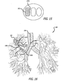
- all of the embodiments of the present invention have the ability to display an overview of the bronchial tree.
- This overview may be obtained from subjective sources such as CT images or objective sources such as medical atlases, etc.
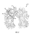
- An example of such an overview 100 is provided in Figure 2 .
- the overview 100 may be displayed on a split screen or on a separate monitor.
- the overview may also be presented in a separate window on the display 86 but it is likely that a physician would benefit from being able to constantly monitor the overview 100.
- the overview 100 includes an indication of a targeted lesion 102 and a path 104 to the lesion 102.
- the path 104 is determined in a pre-operative planning stage, either manually or automatically, or a combination thereof (semi-automatically, for example).
- the path 104 includes a plurality of waypoints or turning points 106a-d enroute to the lesion 102. Navigation to these waypoints 106a-d is supplemented by identifiable anatomical landmarks 107a-e, typically bifurcations, trifurcations, or forks.
- an virtual interior view of the airway will be displayed along with the overview 100.
- This interior view may be realistic, constructed from CT scans, for example, or may be very basic (schematic). Additionally, this may be presented as a perspective or parallel geometric view (i.e. with or without a vanishing point).
- Figures 3, 5 , 7 , 9 , 11 , 13 , 15 , and 17-22 show an interior display which will be presented with the overview 100.
- Various embodiments of the present invention will be demonstrated using the same path 104 and target lesion 102 from Figure 2 .
- FIG. 3-16 A first example is shown in Figures 3-16 .
- the display is shown from a viewpoint just over or beyond the distal tip of the locatable guide. The display remains centered in the airway and does not twist or otherwise move with the movement of the locatable guide except in an axial direction.
- Figure 3 shows the first landmark 107a and the first waypoint 106a. Because the waypoints are turning points and not (necessarily) physical landmarks, the waypoints may be displayed as suspended points that indicate to the physician that upon reaching the waypoint, the physician needs to steer the probe in the next direction. Alternatively, the waypoints need not be displayed. In order to ease navigation, the correct airway will be highlighted somehow, as shown.
- the highlighted airway could change color or blink when the probe reaches the waypoint to indicate a direction change is needed.
- the position of the locatable guide is shown as an arrowhead 108, or some other indication, on the overview 100 as shown in Figure 4 .
- Figure 5 shows that as the locatable guide is advanced the features of the bifurcation marked as landmark 107a grow larger, indicating that the locatable guide is nearing the waypoint 106a.
- the airway along the path remains highlighted to assist the physician in navigating to the lesion 102.
- the arrowhead 108 continues to advance along the path. It is envisioned that the arrowhead 108 may always be depicted along the desired path, thereby providing only an indication of how far along the path the locatable guide has been advance, or more preferably, the arrowhead may float independent of the path, thereby providing indication of the location of the locatable guide in the event that the physician has advanced the tip of the probe down an incorrect airway.
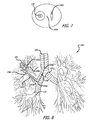
- the view changes to that shown in Figure 7 , with the next waypoint 106b highlighted and an adjacent landmark 107b in the distant field view.
- a more distant bifurcation 110 is depicted, giving depth to the perspective view of the airway.
- This bifurcation labeled for reference purposes in Figure 8 which corresponds to the view in Figure 7 .
- the arrowhead 108 is still visible in Figure 8 but has not advanced considerably past its position in Figure 6 , because crossing the threshold of a waypoint to a different view may be accomplished with a minute actual advancement of the locatable guide.
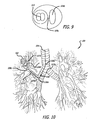
- Figure 9 shows the steady growth of the features 110, 107b and 106b as the locatable guide is advanced.
- Figure 10 shows that the arrowhead 108 is close to approaching the waypoint 106b.
- Figure 12 is the corresponding overview 100 with arrowhead 108 located just past waypoint 106b and pointing in the direction of the next waypoint 106c.
- Landmark 107d is visible with the correct airway highlighted.
- waypoint 106c has not yet been reached and still appears in the distance. This illustrates that landmarks may be used as trigger points to update the views. This is useful for long straight passages that result in passing several anatomical features. Alternatively, only waypoints may be used as trigger points.
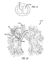
- Figure 14 shows that the arrowhead has advanced past waypoint 106c.
- Figure 15 provides the view after passing landmark 107d and corresponds with the overview 100 shown in Figure 16 .
- the target 102 which is now visible, is highlighted in a different color or pattern than the various waypoints. It is also preferable to provide an indication when the tip of the probe is within an operational proximity to the target 102, such that the physician knows that the appropriate task (biopsy, ablation, excision, etc.) may be performed without further advancing or orienting the probe.
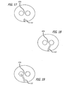
- FIG. 17-22 An embodiment is shown in Figures 17-22 .
- a virtual image of the probe itself is provided and the viewpoint remains fixed just beyond each waypoint.
- the physician may be given the option to advance the waypoint manually, in the event that two waypoints are spaced apart such that the image of the next waypoint is difficult to see.
- Figure 17 shows the first landmark 107a and the tip of the locatable guide or probe 112. In order to ease navigation, the correct airway will be highlighted somehow, as shown. To further assist with navigation, the position of the locatable guide is shown as an arrowhead 108, or some other indication, on the overview 100 as shown in Figure 4 .
- Figure 18 shows that as the locatable guide is advanced the features of the bifurcation marked as landmark 107a remain the same size, but more of the probe 112 becomes visible, as though the probe 112 is advancing past and away from the viewpoint. The probe 112 is approaching the waypoint 106a and the physician can see that the probe 112 is turned toward the correct airway. Also, as seen in Figure 6 , the arrowhead 108 continues to advance along the path.
- the arrowhead 108 may always be depicted along the desired path, thereby providing only an indication of how far along the path the locatable guide has been advance, or more preferably, the arrowhead may float independent of the path, thereby providing indication of the location of the locatable guide in the event that the physician has advanced the tip of the probe down an incorrect airway.
- the viewpoint will not change to the next viewpoint. Rather, the probe 112 remains visible and is shown as advancing down the incorrect airway.
- the virtual probe 112 is constantly representative of the position and orientation of the actual probe.
- the view changes to that shown in Figure 20 , with the next waypoint 106b highlighted in the distant field view.
- a more distant bifurcation 110 is depicted, giving depth to the perspective view of the airway.
- This bifurcation labeled for reference purposes in Figure 8 which corresponds to the view in Figure 20 .
- the arrowhead 108 is still visible in Figure 8 but has not advanced considerably past its position in Figure 19 , because crossing the threshold of a waypoint to a different view may be accomplished with a minute actual advancement of the locatable guide.
- Figure 21 shows the advancement of the probe 112 to a point where the probe may be steered toward the highlighted airway.
- the virtual probe 112 is depicted as deflecting in the direction that the actual probe is deflected.
- Figure 10 shows that the arrowhead 108 is close to approaching the waypoint 106b.
- Figure 22 provides the view after passing waypoint 106c and corresponds with the overview 100 shown in Figure 16 .
- the target 102 which is now visible, is highlighted in a different color or pattern than the various waypoints. It is also preferable to provide an indication when the tip of the probe is within an operational proximity to the target 102, such that the physician knows that the appropriate task (biopsy, ablation, excision, etc.) may be performed without further advancing or orienting the probe.
- the probe 112 itself is highlighted to show that the probe is in operational proximity to the target lesion 102.
- the controlled perspective imaging method of the present invention could be used with a system that uses a navigation device other than a locatable guide, such as an optical navigation system.
- a navigation device other than a locatable guide
- Using inputs such as identifiable landmarks and bronchoscope depth, through image processing the display method of the present invention could be utilized to provide a more user-friendly navigational interface. Accordingly, it is to be understood that the drawings and descriptions herein are proffered by way of example to facilitate comprehension of the invention and should not be construed to limit the scope thereof.
Landscapes
- Health & Medical Sciences (AREA)
- Engineering & Computer Science (AREA)
- Life Sciences & Earth Sciences (AREA)
- Surgery (AREA)
- Medical Informatics (AREA)
- Nuclear Medicine, Radiotherapy & Molecular Imaging (AREA)
- Biomedical Technology (AREA)
- Heart & Thoracic Surgery (AREA)
- Molecular Biology (AREA)
- Animal Behavior & Ethology (AREA)
- General Health & Medical Sciences (AREA)
- Public Health (AREA)
- Veterinary Medicine (AREA)
- Physics & Mathematics (AREA)
- Software Systems (AREA)
- Biophysics (AREA)
- Radiology & Medical Imaging (AREA)
- Pathology (AREA)
- Human Computer Interaction (AREA)
- Gynecology & Obstetrics (AREA)
- Radar, Positioning & Navigation (AREA)
- Remote Sensing (AREA)
- Robotics (AREA)
- Computer Graphics (AREA)
- Computer Hardware Design (AREA)
- General Engineering & Computer Science (AREA)
- General Physics & Mathematics (AREA)
- Theoretical Computer Science (AREA)
- Signal Processing (AREA)
- Optics & Photonics (AREA)
- Apparatus For Radiation Diagnosis (AREA)
- Endoscopes (AREA)
- Magnetic Resonance Imaging Apparatus (AREA)
- Instruments For Viewing The Inside Of Hollow Bodies (AREA)
Claims (5)
- Verfahren zum Anzeigen eines virtuellen Bildes einer Sonde, welche durch ein verzweigtes Netzwerk von Körperlumina navigiert wird, die Generierung eines dynamischen virtuellen Bildes einer sich durch das verzweigte Netzwerk bewegenden Sonde von einem Blickpunkt aus umfassend, welcher sich innerhalb eines Lumens des verzweigten Netzwerkes befindet und in Relation zu einem Punkt auf einem distalen Abschnitt der Sonde fixiert ist, welcher proximal zu einer distalen Spitze der Sonde ist, wobei das dynamische virtuelle Bild einen ersten Zweig des verzweigten Netzwerkes anzeigt, welcher eine erste Orientierungsstelle umfasst, dadurch gekennzeichnet, dass das Verfahren umfasst:Aktualisierung des dynamischen virtuellen Bildes, so dass es von dem Anzeigen des ersten Zweiges zu dem Anzeigen eines zweiten Zweiges des verzweigten Netzwerkes übergeht, welcher eine zweite Orientierungsstelle umfasst, wenn der Blickpunkt einen zuvor bestimmten Wegpunkt der ersten Orientierungsstelle passiert.
- Verfahren gemäß Anspruch 1, ferner das Anzeigen einer Position und einer Ausrichtung einer distalen Spitze der Sonde umfassend, wodurch eine tatsächliche Position und Ausrichtung der Sonde in dem verzweigten Netzwerk angegeben wird.
- Verfahren gemäß Anspruch 1, wobei der zuvor festgelegte Wegpunkt einen Eingang von dem ersten Zweig in den zweiten Zweig angibt.
- Verfahren gemäß Anspruch 1, wobei die erste Orientierungsstelle eine Öffnung in dem verzweigten Netzwerk umfasst, welche von dem ersten Zweig in den zweiten Zweig führt.
- Verfahren gemäß Anspruch 1, wobei der zuvor festgelegte Wegpunkt an die zweite Orientierungsstelle angrenzt.
Priority Applications (1)
| Application Number | Priority Date | Filing Date | Title |
|---|---|---|---|
| EP15185151.6A EP3023055B1 (de) | 2008-02-12 | 2009-02-11 | Verfahren für gesteuerte perspektivenführung |
Applications Claiming Priority (2)
| Application Number | Priority Date | Filing Date | Title |
|---|---|---|---|
| US2809808P | 2008-02-12 | 2008-02-12 | |
| EP09709594.7A EP2247236B1 (de) | 2008-02-12 | 2009-02-11 | Vorrichtung für gesteuerte perspektivenführung |
Related Parent Applications (3)
| Application Number | Title | Priority Date | Filing Date |
|---|---|---|---|
| EP09709594.7A Division EP2247236B1 (de) | 2008-02-12 | 2009-02-11 | Vorrichtung für gesteuerte perspektivenführung |
| EP09709594.7A Division-Into EP2247236B1 (de) | 2008-02-12 | 2009-02-11 | Vorrichtung für gesteuerte perspektivenführung |
| EP09709594.7 Division | 2009-02-11 |
Related Child Applications (1)
| Application Number | Title | Priority Date | Filing Date |
|---|---|---|---|
| EP15185151.6A Division EP3023055B1 (de) | 2008-02-12 | 2009-02-11 | Verfahren für gesteuerte perspektivenführung |
Publications (2)
| Publication Number | Publication Date |
|---|---|
| EP2633811A1 EP2633811A1 (de) | 2013-09-04 |
| EP2633811B1 true EP2633811B1 (de) | 2015-09-16 |
Family
ID=40955747
Family Applications (4)
| Application Number | Title | Priority Date | Filing Date |
|---|---|---|---|
| EP13168297.3A Active EP2633811B1 (de) | 2008-02-12 | 2009-02-11 | Verfahren für gesteuerte Perspektivenführung |
| EP09709594.7A Active EP2247236B1 (de) | 2008-02-12 | 2009-02-11 | Vorrichtung für gesteuerte perspektivenführung |
| EP13168288.2A Active EP2633810B1 (de) | 2008-02-12 | 2009-02-11 | Verfahren für gesteuerte Perspektivenführung |
| EP15185151.6A Active EP3023055B1 (de) | 2008-02-12 | 2009-02-11 | Verfahren für gesteuerte perspektivenführung |
Family Applications After (3)
| Application Number | Title | Priority Date | Filing Date |
|---|---|---|---|
| EP09709594.7A Active EP2247236B1 (de) | 2008-02-12 | 2009-02-11 | Vorrichtung für gesteuerte perspektivenführung |
| EP13168288.2A Active EP2633810B1 (de) | 2008-02-12 | 2009-02-11 | Verfahren für gesteuerte Perspektivenführung |
| EP15185151.6A Active EP3023055B1 (de) | 2008-02-12 | 2009-02-11 | Verfahren für gesteuerte perspektivenführung |
Country Status (4)
| Country | Link |
|---|---|
| US (2) | US10388066B2 (de) |
| EP (4) | EP2633811B1 (de) |
| ES (1) | ES2511033T3 (de) |
| WO (1) | WO2009101504A2 (de) |
Families Citing this family (34)
| Publication number | Priority date | Publication date | Assignee | Title |
|---|---|---|---|---|
| WO2007033206A2 (en) | 2005-09-13 | 2007-03-22 | Veran Medical Technologies, Inc. | Apparatus and method for image guided accuracy verification |
| US20070066881A1 (en) | 2005-09-13 | 2007-03-22 | Edwards Jerome R | Apparatus and method for image guided accuracy verification |
| EP2633811B1 (de) | 2008-02-12 | 2015-09-16 | Covidien LP | Verfahren für gesteuerte Perspektivenführung |
| JP2013517909A (ja) * | 2010-01-28 | 2013-05-20 | ザ ペン ステイト リサーチ ファンデーション | 気管支鏡検査法ガイダンスに適用される画像ベースのグローバル登録 |
| US8672837B2 (en) | 2010-06-24 | 2014-03-18 | Hansen Medical, Inc. | Methods and devices for controlling a shapeable medical device |
| WO2012024686A2 (en) | 2010-08-20 | 2012-02-23 | Veran Medical Technologies, Inc. | Apparatus and method for four dimensional soft tissue navigation |
| US20120197086A1 (en) * | 2011-01-31 | 2012-08-02 | Nellcor Puritan Bennett Llc | Medical visualization technique and apparatus |
| US9138165B2 (en) | 2012-02-22 | 2015-09-22 | Veran Medical Technologies, Inc. | Systems, methods and devices for forming respiratory-gated point cloud for four dimensional soft tissue navigation |
| JP5826082B2 (ja) * | 2012-03-21 | 2015-12-02 | 富士フイルム株式会社 | 医用画像診断支援装置および方法並びにプログラム |
| US10039473B2 (en) | 2012-05-14 | 2018-08-07 | Intuitive Surgical Operations, Inc. | Systems and methods for navigation based on ordered sensor records |
| US10376178B2 (en) | 2012-05-14 | 2019-08-13 | Intuitive Surgical Operations, Inc. | Systems and methods for registration of a medical device using rapid pose search |
| WO2013173227A1 (en) | 2012-05-14 | 2013-11-21 | Intuitive Surgical Operations | Systems and methods for registration of a medical device using a reduced search space |
| JP6128792B2 (ja) * | 2012-10-16 | 2017-05-17 | オリンパス株式会社 | 観察装置、観察支援装置、観察装置の作動方法及びプログラム |
| JP6128796B2 (ja) * | 2012-10-25 | 2017-05-17 | オリンパス株式会社 | 挿入システム、挿入支援装置、挿入支援装置の作動方法及びプログラム |
| US9057600B2 (en) | 2013-03-13 | 2015-06-16 | Hansen Medical, Inc. | Reducing incremental measurement sensor error |
| US9014851B2 (en) | 2013-03-15 | 2015-04-21 | Hansen Medical, Inc. | Systems and methods for tracking robotically controlled medical instruments |
| US9639666B2 (en) * | 2013-03-15 | 2017-05-02 | Covidien Lp | Pathway planning system and method |
| US11020016B2 (en) | 2013-05-30 | 2021-06-01 | Auris Health, Inc. | System and method for displaying anatomy and devices on a movable display |
| US10448861B2 (en) * | 2013-09-06 | 2019-10-22 | Covidien Lp | System and method for light based lung visualization |
| US20150305612A1 (en) | 2014-04-23 | 2015-10-29 | Mark Hunter | Apparatuses and methods for registering a real-time image feed from an imaging device to a steerable catheter |
| US20150305650A1 (en) | 2014-04-23 | 2015-10-29 | Mark Hunter | Apparatuses and methods for endobronchial navigation to and confirmation of the location of a target tissue and percutaneous interception of the target tissue |
| JP6600690B2 (ja) * | 2015-10-20 | 2019-10-30 | オリンパス株式会社 | 挿入体支援システム |
| JP7170631B2 (ja) | 2016-10-05 | 2022-11-14 | ニューヴェイジヴ,インコーポレイテッド | 外科ナビゲーションシステム及び関連する方法 |
| JP6828465B2 (ja) * | 2017-01-30 | 2021-02-10 | セイコーエプソン株式会社 | 内視鏡操作支援システム |
| US11490782B2 (en) | 2017-03-31 | 2022-11-08 | Auris Health, Inc. | Robotic systems for navigation of luminal networks that compensate for physiological noise |
| US10022192B1 (en) | 2017-06-23 | 2018-07-17 | Auris Health, Inc. | Automatically-initialized robotic systems for navigation of luminal networks |
| WO2019125964A1 (en) | 2017-12-18 | 2019-06-27 | Auris Health, Inc. | Methods and systems for instrument tracking and navigation within luminal networks |
| JP7225259B2 (ja) | 2018-03-28 | 2023-02-20 | オーリス ヘルス インコーポレイテッド | 器具の推定位置を示すためのシステム及び方法 |
| EP3801190A4 (de) * | 2018-05-30 | 2022-03-02 | Auris Health, Inc. | Systeme und verfahren zur ortssensorbasierten verzweigungsvorhersage |
| CN112236083A (zh) | 2018-05-31 | 2021-01-15 | 奥瑞斯健康公司 | 用于导航检测生理噪声的管腔网络的机器人系统和方法 |
| CN110831538B (zh) | 2018-05-31 | 2023-01-24 | 奥瑞斯健康公司 | 基于图像的气道分析和映射 |
| CN114340540B (zh) | 2019-08-30 | 2023-07-04 | 奥瑞斯健康公司 | 器械图像可靠性系统和方法 |
| KR20220058569A (ko) | 2019-08-30 | 2022-05-09 | 아우리스 헬스, 인코포레이티드 | 위치 센서의 가중치-기반 정합을 위한 시스템 및 방법 |
| US11612440B2 (en) | 2019-09-05 | 2023-03-28 | Nuvasive, Inc. | Surgical instrument tracking devices and related methods |
Family Cites Families (15)
| Publication number | Priority date | Publication date | Assignee | Title |
|---|---|---|---|---|
| US6346940B1 (en) * | 1997-02-27 | 2002-02-12 | Kabushiki Kaisha Toshiba | Virtualized endoscope system |
| US7343195B2 (en) * | 1999-05-18 | 2008-03-11 | Mediguide Ltd. | Method and apparatus for real time quantitative three-dimensional image reconstruction of a moving organ and intra-body navigation |
| EP2380487B1 (de) | 2002-04-17 | 2021-03-31 | Covidien LP | Endoskopstrukturen zur Suche eines Targets in einer verzweigten Struktur |
| EP1466552B1 (de) | 2002-07-31 | 2007-01-03 | Olympus Corporation | Endoskop |
| US6892090B2 (en) * | 2002-08-19 | 2005-05-10 | Surgical Navigation Technologies, Inc. | Method and apparatus for virtual endoscopy |
| US7881769B2 (en) * | 2002-11-18 | 2011-02-01 | Mediguide Ltd. | Method and system for mounting an MPS sensor on a catheter |
| US6991605B2 (en) * | 2002-12-18 | 2006-01-31 | Siemens Medical Solutions Usa, Inc. | Three-dimensional pictograms for use with medical images |
| US7901348B2 (en) * | 2003-12-12 | 2011-03-08 | University Of Washington | Catheterscope 3D guidance and interface system |
| WO2005067563A2 (en) * | 2004-01-12 | 2005-07-28 | Calypso Medical Technologies, Inc. | Instruments with location markers and methods for tracking instruments through anatomical passageways |
| US7983733B2 (en) * | 2004-10-26 | 2011-07-19 | Stereotaxis, Inc. | Surgical navigation using a three-dimensional user interface |
| CA2605360C (en) * | 2005-04-21 | 2017-03-28 | Asthmatx, Inc. | Control methods and devices for energy delivery |
| US20060281990A1 (en) * | 2005-05-06 | 2006-12-14 | Viswanathan Raju R | User interfaces and navigation methods for vascular navigation |
| US7623900B2 (en) * | 2005-09-02 | 2009-11-24 | Toshiba Medical Visualization Systems Europe, Ltd. | Method for navigating a virtual camera along a biological object with a lumen |
| JP4450786B2 (ja) * | 2005-11-15 | 2010-04-14 | ザイオソフト株式会社 | 画像処理方法および画像処理プログラム |
| EP2633811B1 (de) | 2008-02-12 | 2015-09-16 | Covidien LP | Verfahren für gesteuerte Perspektivenführung |
-
2009
- 2009-02-11 EP EP13168297.3A patent/EP2633811B1/de active Active
- 2009-02-11 EP EP09709594.7A patent/EP2247236B1/de active Active
- 2009-02-11 US US12/369,466 patent/US10388066B2/en active Active
- 2009-02-11 EP EP13168288.2A patent/EP2633810B1/de active Active
- 2009-02-11 EP EP15185151.6A patent/EP3023055B1/de active Active
- 2009-02-11 WO PCT/IB2009/000238 patent/WO2009101504A2/en active Application Filing
- 2009-02-11 ES ES09709594.7T patent/ES2511033T3/es active Active
-
2019
- 2019-08-12 US US16/538,299 patent/US11315323B2/en active Active
Also Published As
| Publication number | Publication date |
|---|---|
| WO2009101504A2 (en) | 2009-08-20 |
| US20190362552A1 (en) | 2019-11-28 |
| EP2633810B1 (de) | 2017-08-30 |
| WO2009101504A3 (en) | 2009-12-23 |
| EP3023055A1 (de) | 2016-05-25 |
| ES2511033T3 (es) | 2014-10-22 |
| EP2247236B1 (de) | 2014-07-30 |
| EP2247236A2 (de) | 2010-11-10 |
| EP2247236A4 (de) | 2012-08-08 |
| US10388066B2 (en) | 2019-08-20 |
| EP3023055B1 (de) | 2017-12-13 |
| US20090209817A1 (en) | 2009-08-20 |
| US11315323B2 (en) | 2022-04-26 |
| EP2633811A1 (de) | 2013-09-04 |
| EP2633810A1 (de) | 2013-09-04 |
Similar Documents
| Publication | Publication Date | Title |
|---|---|---|
| US11315323B2 (en) | Controlled perspective guidance method | |
| US20230346487A1 (en) | Graphical user interface for monitoring an image-guided procedure | |
| US11744445B2 (en) | Method and system for assisting an operator in endoscopic navigation | |
| US20210177299A1 (en) | Method And System For Providing Visual Guidance To An Operator For Steering A Tip Of An Endoscopic Device Towards One Or More Landmarks In A Patient | |
| US20240008762A1 (en) | Graphical user interface for catheter positioning and insertion | |
| EP2411966B1 (de) | System zum bereitstellen von visueller führung zum lenken einer spitze einer endoskopischen einrichtung zu einer oder mehreren landmarken und zum helfen eines bedieners bei endoskopischer navigation | |
| EP2842487B1 (de) | Lokalisierbarer Katheter | |
| US11737663B2 (en) | Target anatomical feature localization | |
| US20220354380A1 (en) | Endoscope navigation system with updating anatomy model | |
| EP4333682A1 (de) | Endoskopnavigationssystem mit aktualisierungsanatomiemodell |
Legal Events
| Date | Code | Title | Description |
|---|---|---|---|
| PUAI | Public reference made under article 153(3) epc to a published international application that has entered the european phase |
Free format text: ORIGINAL CODE: 0009012 |
|
| AC | Divisional application: reference to earlier application |
Ref document number: 2247236 Country of ref document: EP Kind code of ref document: P |
|
| AK | Designated contracting states |
Kind code of ref document: A1 Designated state(s): AT BE BG CH CY CZ DE DK EE ES FI FR GB GR HR HU IE IS IT LI LT LU LV MC MK MT NL NO PL PT RO SE SI SK TR |
|
| 17P | Request for examination filed |
Effective date: 20140304 |
|
| RBV | Designated contracting states (corrected) |
Designated state(s): AT BE BG CH CY CZ DE DK EE ES FI FR GB GR HR HU IE IS IT LI LT LU LV MC MK MT NL NO PL PT RO SE SI SK TR |
|
| GRAP | Despatch of communication of intention to grant a patent |
Free format text: ORIGINAL CODE: EPIDOSNIGR1 |
|
| INTG | Intention to grant announced |
Effective date: 20150327 |
|
| GRAS | Grant fee paid |
Free format text: ORIGINAL CODE: EPIDOSNIGR3 |
|
| GRAA | (expected) grant |
Free format text: ORIGINAL CODE: 0009210 |
|
| RAP1 | Party data changed (applicant data changed or rights of an application transferred) |
Owner name: COVIDIEN LP |
|
| AC | Divisional application: reference to earlier application |
Ref document number: 2247236 Country of ref document: EP Kind code of ref document: P |
|
| AK | Designated contracting states |
Kind code of ref document: B1 Designated state(s): AT BE BG CH CY CZ DE DK EE ES FI FR GB GR HR HU IE IS IT LI LT LU LV MC MK MT NL NO PL PT RO SE SI SK TR |
|
| REG | Reference to a national code |
Ref country code: GB Ref legal event code: FG4D |
|
| REG | Reference to a national code |
Ref country code: CH Ref legal event code: EP |
|
| REG | Reference to a national code |
Ref country code: IE Ref legal event code: FG4D |
|
| REG | Reference to a national code |
Ref country code: AT Ref legal event code: REF Ref document number: 749116 Country of ref document: AT Kind code of ref document: T Effective date: 20151015 |
|
| REG | Reference to a national code |
Ref country code: DE Ref legal event code: R096 Ref document number: 602009033756 Country of ref document: DE |
|
| REG | Reference to a national code |
Ref country code: NL Ref legal event code: MP Effective date: 20150916 |
|
| REG | Reference to a national code |
Ref country code: FR Ref legal event code: PLFP Year of fee payment: 8 |
|
| PG25 | Lapsed in a contracting state [announced via postgrant information from national office to epo] |
Ref country code: FI Free format text: LAPSE BECAUSE OF FAILURE TO SUBMIT A TRANSLATION OF THE DESCRIPTION OR TO PAY THE FEE WITHIN THE PRESCRIBED TIME-LIMIT Effective date: 20150916 Ref country code: LT Free format text: LAPSE BECAUSE OF FAILURE TO SUBMIT A TRANSLATION OF THE DESCRIPTION OR TO PAY THE FEE WITHIN THE PRESCRIBED TIME-LIMIT Effective date: 20150916 Ref country code: GR Free format text: LAPSE BECAUSE OF FAILURE TO SUBMIT A TRANSLATION OF THE DESCRIPTION OR TO PAY THE FEE WITHIN THE PRESCRIBED TIME-LIMIT Effective date: 20151217 Ref country code: NO Free format text: LAPSE BECAUSE OF FAILURE TO SUBMIT A TRANSLATION OF THE DESCRIPTION OR TO PAY THE FEE WITHIN THE PRESCRIBED TIME-LIMIT Effective date: 20151216 Ref country code: LV Free format text: LAPSE BECAUSE OF FAILURE TO SUBMIT A TRANSLATION OF THE DESCRIPTION OR TO PAY THE FEE WITHIN THE PRESCRIBED TIME-LIMIT Effective date: 20150916 |
|
| REG | Reference to a national code |
Ref country code: LT Ref legal event code: MG4D |
|
| REG | Reference to a national code |
Ref country code: AT Ref legal event code: MK05 Ref document number: 749116 Country of ref document: AT Kind code of ref document: T Effective date: 20150916 |
|
| PG25 | Lapsed in a contracting state [announced via postgrant information from national office to epo] |
Ref country code: SE Free format text: LAPSE BECAUSE OF FAILURE TO SUBMIT A TRANSLATION OF THE DESCRIPTION OR TO PAY THE FEE WITHIN THE PRESCRIBED TIME-LIMIT Effective date: 20150916 Ref country code: HR Free format text: LAPSE BECAUSE OF FAILURE TO SUBMIT A TRANSLATION OF THE DESCRIPTION OR TO PAY THE FEE WITHIN THE PRESCRIBED TIME-LIMIT Effective date: 20150916 |
|
| PG25 | Lapsed in a contracting state [announced via postgrant information from national office to epo] |
Ref country code: NL Free format text: LAPSE BECAUSE OF FAILURE TO SUBMIT A TRANSLATION OF THE DESCRIPTION OR TO PAY THE FEE WITHIN THE PRESCRIBED TIME-LIMIT Effective date: 20150916 |
|
| PG25 | Lapsed in a contracting state [announced via postgrant information from national office to epo] |
Ref country code: SK Free format text: LAPSE BECAUSE OF FAILURE TO SUBMIT A TRANSLATION OF THE DESCRIPTION OR TO PAY THE FEE WITHIN THE PRESCRIBED TIME-LIMIT Effective date: 20150916 Ref country code: ES Free format text: LAPSE BECAUSE OF FAILURE TO SUBMIT A TRANSLATION OF THE DESCRIPTION OR TO PAY THE FEE WITHIN THE PRESCRIBED TIME-LIMIT Effective date: 20150916 Ref country code: EE Free format text: LAPSE BECAUSE OF FAILURE TO SUBMIT A TRANSLATION OF THE DESCRIPTION OR TO PAY THE FEE WITHIN THE PRESCRIBED TIME-LIMIT Effective date: 20150916 Ref country code: IS Free format text: LAPSE BECAUSE OF FAILURE TO SUBMIT A TRANSLATION OF THE DESCRIPTION OR TO PAY THE FEE WITHIN THE PRESCRIBED TIME-LIMIT Effective date: 20160116 Ref country code: IT Free format text: LAPSE BECAUSE OF FAILURE TO SUBMIT A TRANSLATION OF THE DESCRIPTION OR TO PAY THE FEE WITHIN THE PRESCRIBED TIME-LIMIT Effective date: 20150916 Ref country code: CZ Free format text: LAPSE BECAUSE OF FAILURE TO SUBMIT A TRANSLATION OF THE DESCRIPTION OR TO PAY THE FEE WITHIN THE PRESCRIBED TIME-LIMIT Effective date: 20150916 |
|
| PG25 | Lapsed in a contracting state [announced via postgrant information from national office to epo] |
Ref country code: PL Free format text: LAPSE BECAUSE OF FAILURE TO SUBMIT A TRANSLATION OF THE DESCRIPTION OR TO PAY THE FEE WITHIN THE PRESCRIBED TIME-LIMIT Effective date: 20150916 Ref country code: BE Free format text: LAPSE BECAUSE OF NON-PAYMENT OF DUE FEES Effective date: 20160229 Ref country code: PT Free format text: LAPSE BECAUSE OF FAILURE TO SUBMIT A TRANSLATION OF THE DESCRIPTION OR TO PAY THE FEE WITHIN THE PRESCRIBED TIME-LIMIT Effective date: 20160118 Ref country code: AT Free format text: LAPSE BECAUSE OF FAILURE TO SUBMIT A TRANSLATION OF THE DESCRIPTION OR TO PAY THE FEE WITHIN THE PRESCRIBED TIME-LIMIT Effective date: 20150916 Ref country code: RO Free format text: LAPSE BECAUSE OF FAILURE TO SUBMIT A TRANSLATION OF THE DESCRIPTION OR TO PAY THE FEE WITHIN THE PRESCRIBED TIME-LIMIT Effective date: 20150916 |
|
| REG | Reference to a national code |
Ref country code: DE Ref legal event code: R097 Ref document number: 602009033756 Country of ref document: DE |
|
| PLBE | No opposition filed within time limit |
Free format text: ORIGINAL CODE: 0009261 |
|
| STAA | Information on the status of an ep patent application or granted ep patent |
Free format text: STATUS: NO OPPOSITION FILED WITHIN TIME LIMIT |
|
| 26N | No opposition filed |
Effective date: 20160617 |
|
| PG25 | Lapsed in a contracting state [announced via postgrant information from national office to epo] |
Ref country code: DK Free format text: LAPSE BECAUSE OF FAILURE TO SUBMIT A TRANSLATION OF THE DESCRIPTION OR TO PAY THE FEE WITHIN THE PRESCRIBED TIME-LIMIT Effective date: 20150916 |
|
| PG25 | Lapsed in a contracting state [announced via postgrant information from national office to epo] |
Ref country code: LU Free format text: LAPSE BECAUSE OF FAILURE TO SUBMIT A TRANSLATION OF THE DESCRIPTION OR TO PAY THE FEE WITHIN THE PRESCRIBED TIME-LIMIT Effective date: 20160211 Ref country code: MC Free format text: LAPSE BECAUSE OF FAILURE TO SUBMIT A TRANSLATION OF THE DESCRIPTION OR TO PAY THE FEE WITHIN THE PRESCRIBED TIME-LIMIT Effective date: 20150916 |
|
| REG | Reference to a national code |
Ref country code: CH Ref legal event code: PL |
|
| PG25 | Lapsed in a contracting state [announced via postgrant information from national office to epo] |
Ref country code: LI Free format text: LAPSE BECAUSE OF NON-PAYMENT OF DUE FEES Effective date: 20160229 Ref country code: CH Free format text: LAPSE BECAUSE OF NON-PAYMENT OF DUE FEES Effective date: 20160229 |
|
| PG25 | Lapsed in a contracting state [announced via postgrant information from national office to epo] |
Ref country code: SI Free format text: LAPSE BECAUSE OF FAILURE TO SUBMIT A TRANSLATION OF THE DESCRIPTION OR TO PAY THE FEE WITHIN THE PRESCRIBED TIME-LIMIT Effective date: 20150916 |
|
| REG | Reference to a national code |
Ref country code: IE Ref legal event code: MM4A |
|
| PG25 | Lapsed in a contracting state [announced via postgrant information from national office to epo] |
Ref country code: BE Free format text: LAPSE BECAUSE OF FAILURE TO SUBMIT A TRANSLATION OF THE DESCRIPTION OR TO PAY THE FEE WITHIN THE PRESCRIBED TIME-LIMIT Effective date: 20150916 |
|
| REG | Reference to a national code |
Ref country code: FR Ref legal event code: PLFP Year of fee payment: 9 |
|
| PG25 | Lapsed in a contracting state [announced via postgrant information from national office to epo] |
Ref country code: IE Free format text: LAPSE BECAUSE OF NON-PAYMENT OF DUE FEES Effective date: 20160211 |
|
| PG25 | Lapsed in a contracting state [announced via postgrant information from national office to epo] |
Ref country code: MT Free format text: LAPSE BECAUSE OF FAILURE TO SUBMIT A TRANSLATION OF THE DESCRIPTION OR TO PAY THE FEE WITHIN THE PRESCRIBED TIME-LIMIT Effective date: 20150916 |
|
| REG | Reference to a national code |
Ref country code: FR Ref legal event code: PLFP Year of fee payment: 10 |
|
| PG25 | Lapsed in a contracting state [announced via postgrant information from national office to epo] |
Ref country code: HU Free format text: LAPSE BECAUSE OF FAILURE TO SUBMIT A TRANSLATION OF THE DESCRIPTION OR TO PAY THE FEE WITHIN THE PRESCRIBED TIME-LIMIT; INVALID AB INITIO Effective date: 20090211 Ref country code: CY Free format text: LAPSE BECAUSE OF FAILURE TO SUBMIT A TRANSLATION OF THE DESCRIPTION OR TO PAY THE FEE WITHIN THE PRESCRIBED TIME-LIMIT Effective date: 20150916 |
|
| PG25 | Lapsed in a contracting state [announced via postgrant information from national office to epo] |
Ref country code: MK Free format text: LAPSE BECAUSE OF FAILURE TO SUBMIT A TRANSLATION OF THE DESCRIPTION OR TO PAY THE FEE WITHIN THE PRESCRIBED TIME-LIMIT Effective date: 20150916 Ref country code: TR Free format text: LAPSE BECAUSE OF FAILURE TO SUBMIT A TRANSLATION OF THE DESCRIPTION OR TO PAY THE FEE WITHIN THE PRESCRIBED TIME-LIMIT Effective date: 20150916 Ref country code: MT Free format text: LAPSE BECAUSE OF FAILURE TO SUBMIT A TRANSLATION OF THE DESCRIPTION OR TO PAY THE FEE WITHIN THE PRESCRIBED TIME-LIMIT Effective date: 20160229 |
|
| PG25 | Lapsed in a contracting state [announced via postgrant information from national office to epo] |
Ref country code: BG Free format text: LAPSE BECAUSE OF FAILURE TO SUBMIT A TRANSLATION OF THE DESCRIPTION OR TO PAY THE FEE WITHIN THE PRESCRIBED TIME-LIMIT Effective date: 20150916 |
|
| PGFP | Annual fee paid to national office [announced via postgrant information from national office to epo] |
Ref country code: FR Payment date: 20230119 Year of fee payment: 15 |
|
| PGFP | Annual fee paid to national office [announced via postgrant information from national office to epo] |
Ref country code: DE Payment date: 20240123 Year of fee payment: 16 Ref country code: GB Payment date: 20240123 Year of fee payment: 16 |