EP2633248B1 - Dachanker zur fixierung von rahmenstrukturen auf einem dach - Google Patents
Dachanker zur fixierung von rahmenstrukturen auf einem dach Download PDFInfo
- Publication number
- EP2633248B1 EP2633248B1 EP11776159.3A EP11776159A EP2633248B1 EP 2633248 B1 EP2633248 B1 EP 2633248B1 EP 11776159 A EP11776159 A EP 11776159A EP 2633248 B1 EP2633248 B1 EP 2633248B1
- Authority
- EP
- European Patent Office
- Prior art keywords
- roof
- protrusion
- anchor
- fitting
- fixing frame
- Prior art date
- Legal status (The legal status is an assumption and is not a legal conclusion. Google has not performed a legal analysis and makes no representation as to the accuracy of the status listed.)
- Active
Links
Images
Classifications
-
- F—MECHANICAL ENGINEERING; LIGHTING; HEATING; WEAPONS; BLASTING
- F24—HEATING; RANGES; VENTILATING
- F24S—SOLAR HEAT COLLECTORS; SOLAR HEAT SYSTEMS
- F24S25/00—Arrangement of stationary mountings or supports for solar heat collector modules
- F24S25/60—Fixation means, e.g. fasteners, specially adapted for supporting solar heat collector modules
- F24S25/61—Fixation means, e.g. fasteners, specially adapted for supporting solar heat collector modules for fixing to the ground or to building structures
-
- F—MECHANICAL ENGINEERING; LIGHTING; HEATING; WEAPONS; BLASTING
- F24—HEATING; RANGES; VENTILATING
- F24S—SOLAR HEAT COLLECTORS; SOLAR HEAT SYSTEMS
- F24S25/00—Arrangement of stationary mountings or supports for solar heat collector modules
- F24S25/30—Arrangement of stationary mountings or supports for solar heat collector modules using elongate rigid mounting elements extending substantially along the supporting surface, e.g. for covering buildings with solar heat collectors
- F24S25/33—Arrangement of stationary mountings or supports for solar heat collector modules using elongate rigid mounting elements extending substantially along the supporting surface, e.g. for covering buildings with solar heat collectors forming substantially planar assemblies, e.g. of coplanar or stacked profiles
-
- Y—GENERAL TAGGING OF NEW TECHNOLOGICAL DEVELOPMENTS; GENERAL TAGGING OF CROSS-SECTIONAL TECHNOLOGIES SPANNING OVER SEVERAL SECTIONS OF THE IPC; TECHNICAL SUBJECTS COVERED BY FORMER USPC CROSS-REFERENCE ART COLLECTIONS [XRACs] AND DIGESTS
- Y02—TECHNOLOGIES OR APPLICATIONS FOR MITIGATION OR ADAPTATION AGAINST CLIMATE CHANGE
- Y02B—CLIMATE CHANGE MITIGATION TECHNOLOGIES RELATED TO BUILDINGS, e.g. HOUSING, HOUSE APPLIANCES OR RELATED END-USER APPLICATIONS
- Y02B10/00—Integration of renewable energy sources in buildings
- Y02B10/20—Solar thermal
-
- Y—GENERAL TAGGING OF NEW TECHNOLOGICAL DEVELOPMENTS; GENERAL TAGGING OF CROSS-SECTIONAL TECHNOLOGIES SPANNING OVER SEVERAL SECTIONS OF THE IPC; TECHNICAL SUBJECTS COVERED BY FORMER USPC CROSS-REFERENCE ART COLLECTIONS [XRACs] AND DIGESTS
- Y02—TECHNOLOGIES OR APPLICATIONS FOR MITIGATION OR ADAPTATION AGAINST CLIMATE CHANGE
- Y02E—REDUCTION OF GREENHOUSE GAS [GHG] EMISSIONS, RELATED TO ENERGY GENERATION, TRANSMISSION OR DISTRIBUTION
- Y02E10/00—Energy generation through renewable energy sources
- Y02E10/40—Solar thermal energy, e.g. solar towers
- Y02E10/47—Mountings or tracking
Definitions
- the present invention relates to a roof anchor and system for fixing frame structures to a roof
- the roof anchor comprising of: a base structure configured to be mounted on a roofing surface, the base structure comprising of a base and a substantially circular protrusion with a top part having a substantially planar top surface, the protrusion further having a reduced circumference at its lower end defining a gap encircling the protrusion, the roof anchor further comprising a top fitting comprising a guide.
- Solar panels have become increasingly popular due to, among others, focus on reduction of emission of CO2 and reductions in production and acquisition costs.
- Solar panels both photovoltaic and solar thermal, are mounted as integrated parts of new buildings and also retrofitted to existing building stock.
- Adjusting non-aligned mountings on a roof may be difficult and time consuming, especially due to requirements regarding waterproof properties.
- roof structures it is therefore desirable to keep requirements in relation to tolerances and precision to a minimum.
- WO 0128811 A1 discloses an anchorage including two members; one fixed to one end of a strap or other element to be secured. The members hook interlock ably together upon pull on the strap.
- One member usually the fixed one, may be a stud of mushroom form while the other may be a D-shaped plate with a curved periphery extending out of the plane of the plate to form a U-shaped channel that can hook onto the head of the stud.
- DE 10 2008 012 717 A1 discloses a roof mounting device having a base plate arranged at a lower end of a support unit, and a fixing geometry part, such as flange disk, arranged at an upper end of the unit.
- the unit has upper and lower support segments adjusted relative to each other.
- the plate is arranged at the lower segment, and the geometry part is arranged at the upper segment.
- a flange is arranged at an outer circumference of the upper segment.
- the segments are designed as a thread sleeve and a threaded spindle.
- a polyamide disk is arranged between the geometry part and the flange.
- AU 2003 231 587 A discloses a foot assembly comprising a pair of base elements.
- Each base element includes a horizontal leg, a vertical leg and a first pivotal attachment point for each vertical leg.
- the assembly further includes complementary elements associated with the pair of base elements and each complementary element includes a securing member, and an attachment member.
- Each complementary element being pivotally joined to a respective base element through a connection between one of the first pivotal attachment points and one of the attachment members.
- the present invention seeks to provide an improved device and system for mounting frame structures on a roof top.
- a roof anchor to be mounted directly on a roof , top and for fixing frame structures to a roof
- said roof anchor comprising; a base structure configured to be mounted directly on a roof top on a roofing surface and a substantially circular protrusion with a top part having a substantially planar top surface, the protrusion further having a reduced circumference at its lower end defining a gap encircling the protrusion
- the roof anchor further comprises a top fitting comprising a guide which is constituted by a substantially planar sheet and folds defining a second set of gaps, the planar sheet spans the length and width of the top fitting and defines a top face
- the guide constitutes a bracket for receiving equipment or construction elements, the bracket comprising two opposite faces extending perpendicularly from said top face of said sheet
- the top fitting further is configured for engagement with said top part of said protrusion and wherein the top fitting is able to rotate in relation to the base structure when the gaps of the guide of the top fitting are in engagement with the top part of the pro
- the base structure can be mounted on e.g. a roof top without particular regard to the angular orientation of the base structure as the base structure is not directional.
- the angular orientation of the roof anchor is determined by the top fitting. As the top fitting may be rotated after having been connected to the base structure, the angular orientation of the roof anchor can be adjusted after the base structure has been mounted on a roof.
- a non directional roof anchor that may improve the construction process, is achieved.
- the top part of the protrusion is able to move or slide in a longitudinal direction in the guide of said top fitting when the guide is in engagement with the top part of the protrusion.
- a system for fixing solar panels to a roof by the system constituting a frame structure on which solar panels can be mounted, the system comprising; four or more roof anchors as described above, a first set of beams adapted for being mounted on said top fittings of said roof anchors, a second set of beams adapted for being mounted on first set of beams, wherein the base structures of the roof anchors are configured for being mounted without particular regard to their angular orientation and the top fittings are able to rotate in relation to the base structures when the guides of the top fittings are in engagement with the top parts of the protrusions.
- the disclosed invention can be used for mounting many different kinds of equipment such as photovoltaic solar panels, thermal solar panels or solar collectors but not limited hereto. It is obvious to the person skilled that the present invention can be used for mounting many different kinds of equipment such as e.g. billboards, cooling panels, terraces, air duct channels or the like.
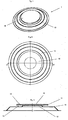
- a roof anchor according an embodiment of the invention comprises a base structure and a top fitting.
- the base structure 1 comprises a base 13 and protrusion 10 extending from the centre of the base 13.
- the protrusion is substantially circular and has a substantially planar top surface 15.
- the protrusion 10 has a lower end 12 adjacent the base 13 and a top part 11 opposite the lower end 12.
- the lower end 12 of the protrusion 10 has a reduced circumference compared to the top part 11.
- the top part thereby constitutes a projecting rim or flange on the protrusion 10.
- a first gap 14 encircling the lower end of protrusion is defined.
- the base structure may be mounted directly on a roof top.
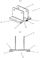
- the top fitting 2 comprises a guide 20 constituted by substantially planar sheet 22 and folds 21 defining a second set of gaps 24.
- the sheet 22 spans the length and the width of the top fitting 2 and defines a top face.
- the folds 21 are arranged along two opposite edges of the sheet 22 and may run along the entire length of the sheet 22.
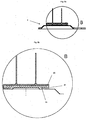
- the folds 21 are adapted to engage with the protrusion 10 of the base structure 1 by receiving the top part 11 in the second set of gaps 24.
- the top fitting 2 further comprises two opposite faces 23 extending perpendicular from the top face of the sheet 22.
- the faces 23 constitutes a bracket e.g. for mounting equipment or construction elements and may comprise one or more through going holes.
- two bendable holding flaps 25 are arranged at the two edges not comprising the folds.
- the bendable holding flaps 25 extend parallel to the sheet 22 prior to bending.
- the bendable holding flaps 25 may be bent to a position substantially perpendicular to the sheet 22.
- the bend holding flaps 25 keeps the top fitting 2 from being accidentally removed from the base structure 1. After having bent the holding flaps 25, the top fitting 2 may still be rotated and/or moved on top of the base structure.
- the base structure 1 and the top fitting 2 constitutes a non directional roof anchor 4.
- This roof anchor 4 may be used in building structures or foundations for mounting solar panels.
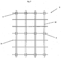
- such structure 3 may comprise a number roof anchors 4 mounted on e.g. a roof top.
- a first set of beams 30 such as but not limited to extruded profiles, bars, girders or rafters are mounted on to of the top fittings 2.
- a second set of beams 31 may be arranged.
- Solar panels may be mounted either directly on top of the first or second set of beams (30, 31).
- the top part 11 of the protrusion may have a substantially spherical or conical shape and/or inclining top surfaces 15.
- the guide 20 and, accordingly, the sheet 22 of the top fitting 2 may also have a substantially spherical or conical shape and/or inclining surfaces for engagement with the protrusion 10.
- the sheet 22 of the top fitting 2 may have an additional fold along a central portion parallel to the folds 21. By incorporating an additional fold the sheet 22 have a top surface inclining downwards from a central portion towards the edges of the sheet 22. Having inclining surfaces on the top part 11 and the top fitting 2 may be beneficial in regard to water flow-off or for other reasons.
Landscapes
- Engineering & Computer Science (AREA)
- Physics & Mathematics (AREA)
- Life Sciences & Earth Sciences (AREA)
- Sustainable Development (AREA)
- Sustainable Energy (AREA)
- Thermal Sciences (AREA)
- Chemical & Material Sciences (AREA)
- Combustion & Propulsion (AREA)
- Mechanical Engineering (AREA)
- General Engineering & Computer Science (AREA)
- Roof Covering Using Slabs Or Stiff Sheets (AREA)
Claims (7)
- Dachanker (4), welcher zur unmittelbaren Montage auf einem Aufdach und zur Fixierung von Rahmenstrukturen auf einem Dach ausgebildet ist, welcher Dachanker (4) folgendes umfasst;• eine Basiskonstruktion (1) zur unmittelbaren Montage auf einem Aufdach auf einer Dachfläche, wobei die Basiskonstruktion eine Basis (13) und einen im Wesentlichen kreisförmigen Vorsprung (10) mit einem oberen Teil (11) mit einer im Wesentlichen ebenen oberen Oberfläche (15) umfasst, wobei der Vorsprung (10) ferner an seinem unteren Ende (12) einen reduzierten Umfang aufweist, welcher einen den Vorsprung umgebenden Spalt (14) definiert,• ein oberer Verbindungsstück (2) umfassend eine Führung (20), welche durch eine im Wesentlichen ebene Platte (22) und Falte (21), die einen zweiten Satz von Spalten (24) definieren, gebildet ist, wobei die ebene Platte (22) die Länge und Breite des oberen Verbindungsstücks überspannt und eine obere Fläche definiert,wobei die Führung (20) einen Halter (23) zur Aufnahme von Ausrüstung oder Bauelementen bildet, welcher Halter (23) zwei entgegengesetzte Flächen (23) umfasst, die sich senkrecht von der oberen Fläche der Platte (22) erstrecken, wobei das obere Verbindungsstück (2) ferner dazu ausgebildet ist, mit dem oberen Teil (11) des Vorsprungs (10) in Eingriff zu gelangen,
und dass das obere Verbindungsstück (2) dazu im Stande ist, relativ zur Basiskonstruktion (1) zu rotieren, wenn sich die Spalte (24) der Führung (20) des oberen Verbindungsstücks (2) mit dem oberen Teil (11) des Vorsprungs (10) im Eingriff befinden. - Dachanker (4) zur Fixierung von Rahmenstrukturen an einem Dach nach Anspruch 1, wobei der obere Teil (11) des Vorsprungs (10) dazu im Stande ist, sich in einer Längsrichtung in der Führung (20) des oberen Verbindungsstücks (2) zu bewegen oder zu gleiten, wenn sich die Führung (20) mit dem oberen Teil (11) des Vorsprungs (10) im Eingriff befindet.
- Dachanker (4) zur Fixierung von Rahmenstrukturen an einem Dach nach einem der vorgehenden Ansprüche, wobei der im Wesentlichen kreisförmige Vorsprung (10) der Basiskonstruktion (1) von einer Mitte der Basis (13) vorspringt.
- Dachanker (4) zur Fixierung von Rahmenstrukturen an einem Dach nach einem der vorgehenden Ansprüche, wobei die obere Oberfläche (15) des Vorsprungs (10) zumindest teilweise geneigt ist.
- Dachanker (4) zur Fixierung von Rahmenstrukturen an einem Dach nach einem der vorgehenden Ansprüche, wobei eine obere Fläche des oberen Verbindungsstücks (2) zumindest teilweise geneigt ist.
- Dachanker (4) zur Fixierung von Rahmenstrukturen an einem Dach nach einem der vorgehenden Ansprüche, wobei der Dachanker eine Sonnenenergieinstallationsvorrichtung ist.
- System zur Fixierung von Solarpanelen auf einem Dach durch das System, welches eine Rahmenstruktur bildet, an welcher Solarpanele montiert werden können, welches System umfasst;• vier oder mehrere Dachanker (4) nach einem der Ansprüche 1-6,• einen ersten Satz von Trägern (30), die für das Montieren auf den oberen Verbindungsstücken (2) der Dachanker (4) ausgebildet sind,• einen zweiten Satz von Trägern (31), die für das Montieren auf dem ersten Satz von Trägern (30) ausgebildet sind,wobei die Basiskonstruktionen (1) der Dachanker (4) für das Montieren ohne Rücksicht auf ihre Winkelausrichtung ausgebildet sind, und die oberen Verbindungsstücke (2) dazu im Stande sind, relativ zu den Basiskonstruktionen (1) zu rotieren, wenn sich die Führungen (20) der oberen Verbindungsstücke (2) mit den oberen Teilen (11) der Vorsprünge (10) im Eingriff befinden.
Applications Claiming Priority (2)
| Application Number | Priority Date | Filing Date | Title |
|---|---|---|---|
| DKPA201070452 | 2010-10-27 | ||
| PCT/EP2011/068785 WO2012055927A2 (en) | 2010-10-27 | 2011-10-26 | Roof anchor for fixing frame structures to a roof |
Publications (2)
| Publication Number | Publication Date |
|---|---|
| EP2633248A2 EP2633248A2 (de) | 2013-09-04 |
| EP2633248B1 true EP2633248B1 (de) | 2016-02-24 |
Family
ID=44883242
Family Applications (1)
| Application Number | Title | Priority Date | Filing Date |
|---|---|---|---|
| EP11776159.3A Active EP2633248B1 (de) | 2010-10-27 | 2011-10-26 | Dachanker zur fixierung von rahmenstrukturen auf einem dach |
Country Status (4)
| Country | Link |
|---|---|
| EP (1) | EP2633248B1 (de) |
| DK (1) | DK2633248T3 (de) |
| ES (1) | ES2571528T3 (de) |
| WO (1) | WO2012055927A2 (de) |
Family Cites Families (8)
| Publication number | Priority date | Publication date | Assignee | Title |
|---|---|---|---|---|
| DE8418908U1 (de) * | 1984-06-21 | 1984-09-27 | Helbling, Albert, 7831 Sasbach | Haltevorrichtung mit halterung fuer sonnenkollektoren |
| CA2387866A1 (en) | 1999-10-21 | 2001-04-26 | C.N. Unwin Limited | Improvements relating to anchorages |
| AU2003231587B2 (en) * | 2002-08-08 | 2009-01-08 | Neil Frederick Edney | Support Assembly and Components Therefor |
| DE202007005995U1 (de) * | 2007-04-24 | 2007-06-28 | Ideematic Deutschland Gmbh | Stützsystem |
| US8609977B2 (en) * | 2008-01-29 | 2013-12-17 | Sunpower Corporation | Self ballasted celestial tracking apparatus |
| DE102008012717A1 (de) * | 2008-03-05 | 2009-09-10 | Wilhelm Flender Gmbh & Co. Kg | Aufnahmeelement |
| DE202009015787U1 (de) * | 2009-11-18 | 2010-03-04 | Harald Zahn Gmbh | Montagevorrichtung für Solaranlagen auf Flachdächern |
| DE202010001933U1 (de) * | 2010-02-05 | 2010-05-20 | Frohberg, Frank | Montagefuß für auf Flachdächern montierte Solaranlagen |
-
2011
- 2011-10-26 EP EP11776159.3A patent/EP2633248B1/de active Active
- 2011-10-26 WO PCT/EP2011/068785 patent/WO2012055927A2/en not_active Ceased
- 2011-10-26 DK DK11776159.3T patent/DK2633248T3/en active
- 2011-10-26 ES ES11776159T patent/ES2571528T3/es active Active
Also Published As
| Publication number | Publication date |
|---|---|
| EP2633248A2 (de) | 2013-09-04 |
| WO2012055927A2 (en) | 2012-05-03 |
| WO2012055927A3 (en) | 2012-08-02 |
| ES2571528T3 (es) | 2016-05-25 |
| DK2633248T3 (en) | 2016-05-17 |
Similar Documents
| Publication | Publication Date | Title |
|---|---|---|
| JP5901615B2 (ja) | カーテンウォール固定用可変型ファスナー | |
| US7658356B1 (en) | Mounting bracket for solar panel applications | |
| US11939781B2 (en) | Fall protection system | |
| ES2924093T3 (es) | Sistema de fijación para montar en techos y uso de dicho sistema de fijación | |
| US9252310B2 (en) | Wear reduction system for rooftop mounts | |
| US9595911B2 (en) | Tile roof mounting systems | |
| JP2011243983A (ja) | ソーラーモジュール用の架設脚及び架設システム | |
| KR101903727B1 (ko) | 지붕일체형 패널시스템 | |
| CN102209826A (zh) | 用于导入负荷力如绳索力或面结构的张力的负荷接收装置 | |
| KR20110113652A (ko) | 장착 클립 | |
| JP5721015B2 (ja) | 支持材の取付構造、及びその施工方法 | |
| CN112726909A (zh) | 曲形屋面幕墙系统 | |
| EP2404126B1 (de) | Montageabschnitt für sonnenpaneele | |
| JP5527290B2 (ja) | 支持金具 | |
| CN113309301B (zh) | 一种金属屋面板固定座 | |
| DK2633248T3 (en) | Taganker for attaching the frame structures for a roof | |
| JP4589178B2 (ja) | 風力発電装置およびその設置方法 | |
| AU2015100513A4 (en) | Flexible Roof Mounting System for Small Wind Turbine Generators | |
| JP2012209892A (ja) | 支持柱及びその設置方法 | |
| JP2013142273A (ja) | 支持装置 | |
| KR100575429B1 (ko) | 골조고정구 | |
| KR101319842B1 (ko) | 어닝용 고정 브라켓 | |
| JP2020180465A (ja) | 庇 | |
| EP4673693A1 (de) | Vorrichtung zur befestigung eines solarpaneels an einer tragschiene und anordnung mit einer tragschiene und einer solchen vorrichtung | |
| JP4507897B2 (ja) | 勾配屋根の軒先構造 |
Legal Events
| Date | Code | Title | Description |
|---|---|---|---|
| PUAI | Public reference made under article 153(3) epc to a published international application that has entered the european phase |
Free format text: ORIGINAL CODE: 0009012 |
|
| 17P | Request for examination filed |
Effective date: 20130523 |
|
| AK | Designated contracting states |
Kind code of ref document: A2 Designated state(s): AL AT BE BG CH CY CZ DE DK EE ES FI FR GB GR HR HU IE IS IT LI LT LU LV MC MK MT NL NO PL PT RO RS SE SI SK SM TR |
|
| DAX | Request for extension of the european patent (deleted) | ||
| GRAP | Despatch of communication of intention to grant a patent |
Free format text: ORIGINAL CODE: EPIDOSNIGR1 |
|
| INTG | Intention to grant announced |
Effective date: 20150731 |
|
| GRAS | Grant fee paid |
Free format text: ORIGINAL CODE: EPIDOSNIGR3 |
|
| GRAA | (expected) grant |
Free format text: ORIGINAL CODE: 0009210 |
|
| AK | Designated contracting states |
Kind code of ref document: B1 Designated state(s): AL AT BE BG CH CY CZ DE DK EE ES FI FR GB GR HR HU IE IS IT LI LT LU LV MC MK MT NL NO PL PT RO RS SE SI SK SM TR |
|
| REG | Reference to a national code |
Ref country code: GB Ref legal event code: FG4D Ref country code: NL Ref legal event code: FP |
|
| REG | Reference to a national code |
Ref country code: CH Ref legal event code: EP |
|
| REG | Reference to a national code |
Ref country code: AT Ref legal event code: REF Ref document number: 776935 Country of ref document: AT Kind code of ref document: T Effective date: 20160315 |
|
| REG | Reference to a national code |
Ref country code: IE Ref legal event code: FG4D |
|
| REG | Reference to a national code |
Ref country code: DE Ref legal event code: R096 Ref document number: 602011023450 Country of ref document: DE |
|
| REG | Reference to a national code |
Ref country code: DK Ref legal event code: T3 Effective date: 20160510 |
|
| REG | Reference to a national code |
Ref country code: SE Ref legal event code: TRGR |
|
| REG | Reference to a national code |
Ref country code: ES Ref legal event code: FG2A Ref document number: 2571528 Country of ref document: ES Kind code of ref document: T3 Effective date: 20160525 |
|
| REG | Reference to a national code |
Ref country code: LT Ref legal event code: MG4D |
|
| REG | Reference to a national code |
Ref country code: NO Ref legal event code: T2 Effective date: 20160224 |
|
| REG | Reference to a national code |
Ref country code: AT Ref legal event code: MK05 Ref document number: 776935 Country of ref document: AT Kind code of ref document: T Effective date: 20160224 |
|
| PG25 | Lapsed in a contracting state [announced via postgrant information from national office to epo] |
Ref country code: GR Free format text: LAPSE BECAUSE OF FAILURE TO SUBMIT A TRANSLATION OF THE DESCRIPTION OR TO PAY THE FEE WITHIN THE PRESCRIBED TIME-LIMIT Effective date: 20160525 Ref country code: FI Free format text: LAPSE BECAUSE OF FAILURE TO SUBMIT A TRANSLATION OF THE DESCRIPTION OR TO PAY THE FEE WITHIN THE PRESCRIBED TIME-LIMIT Effective date: 20160224 Ref country code: HR Free format text: LAPSE BECAUSE OF FAILURE TO SUBMIT A TRANSLATION OF THE DESCRIPTION OR TO PAY THE FEE WITHIN THE PRESCRIBED TIME-LIMIT Effective date: 20160224 |
|
| PG25 | Lapsed in a contracting state [announced via postgrant information from national office to epo] |
Ref country code: LT Free format text: LAPSE BECAUSE OF FAILURE TO SUBMIT A TRANSLATION OF THE DESCRIPTION OR TO PAY THE FEE WITHIN THE PRESCRIBED TIME-LIMIT Effective date: 20160224 Ref country code: PL Free format text: LAPSE BECAUSE OF FAILURE TO SUBMIT A TRANSLATION OF THE DESCRIPTION OR TO PAY THE FEE WITHIN THE PRESCRIBED TIME-LIMIT Effective date: 20160224 Ref country code: AT Free format text: LAPSE BECAUSE OF FAILURE TO SUBMIT A TRANSLATION OF THE DESCRIPTION OR TO PAY THE FEE WITHIN THE PRESCRIBED TIME-LIMIT Effective date: 20160224 Ref country code: RS Free format text: LAPSE BECAUSE OF FAILURE TO SUBMIT A TRANSLATION OF THE DESCRIPTION OR TO PAY THE FEE WITHIN THE PRESCRIBED TIME-LIMIT Effective date: 20160224 Ref country code: PT Free format text: LAPSE BECAUSE OF FAILURE TO SUBMIT A TRANSLATION OF THE DESCRIPTION OR TO PAY THE FEE WITHIN THE PRESCRIBED TIME-LIMIT Effective date: 20160624 Ref country code: LV Free format text: LAPSE BECAUSE OF FAILURE TO SUBMIT A TRANSLATION OF THE DESCRIPTION OR TO PAY THE FEE WITHIN THE PRESCRIBED TIME-LIMIT Effective date: 20160224 |
|
| REG | Reference to a national code |
Ref country code: FR Ref legal event code: PLFP Year of fee payment: 6 |
|
| PG25 | Lapsed in a contracting state [announced via postgrant information from national office to epo] |
Ref country code: EE Free format text: LAPSE BECAUSE OF FAILURE TO SUBMIT A TRANSLATION OF THE DESCRIPTION OR TO PAY THE FEE WITHIN THE PRESCRIBED TIME-LIMIT Effective date: 20160224 |
|
| REG | Reference to a national code |
Ref country code: DE Ref legal event code: R097 Ref document number: 602011023450 Country of ref document: DE |
|
| PG25 | Lapsed in a contracting state [announced via postgrant information from national office to epo] |
Ref country code: RO Free format text: LAPSE BECAUSE OF FAILURE TO SUBMIT A TRANSLATION OF THE DESCRIPTION OR TO PAY THE FEE WITHIN THE PRESCRIBED TIME-LIMIT Effective date: 20160224 Ref country code: SK Free format text: LAPSE BECAUSE OF FAILURE TO SUBMIT A TRANSLATION OF THE DESCRIPTION OR TO PAY THE FEE WITHIN THE PRESCRIBED TIME-LIMIT Effective date: 20160224 Ref country code: CZ Free format text: LAPSE BECAUSE OF FAILURE TO SUBMIT A TRANSLATION OF THE DESCRIPTION OR TO PAY THE FEE WITHIN THE PRESCRIBED TIME-LIMIT Effective date: 20160224 Ref country code: SM Free format text: LAPSE BECAUSE OF FAILURE TO SUBMIT A TRANSLATION OF THE DESCRIPTION OR TO PAY THE FEE WITHIN THE PRESCRIBED TIME-LIMIT Effective date: 20160224 |
|
| PG25 | Lapsed in a contracting state [announced via postgrant information from national office to epo] |
Ref country code: BE Free format text: LAPSE BECAUSE OF FAILURE TO SUBMIT A TRANSLATION OF THE DESCRIPTION OR TO PAY THE FEE WITHIN THE PRESCRIBED TIME-LIMIT Effective date: 20160224 |
|
| PLBE | No opposition filed within time limit |
Free format text: ORIGINAL CODE: 0009261 |
|
| STAA | Information on the status of an ep patent application or granted ep patent |
Free format text: STATUS: NO OPPOSITION FILED WITHIN TIME LIMIT |
|
| 26N | No opposition filed |
Effective date: 20161125 |
|
| PG25 | Lapsed in a contracting state [announced via postgrant information from national office to epo] |
Ref country code: SI Free format text: LAPSE BECAUSE OF FAILURE TO SUBMIT A TRANSLATION OF THE DESCRIPTION OR TO PAY THE FEE WITHIN THE PRESCRIBED TIME-LIMIT Effective date: 20160224 Ref country code: BG Free format text: LAPSE BECAUSE OF FAILURE TO SUBMIT A TRANSLATION OF THE DESCRIPTION OR TO PAY THE FEE WITHIN THE PRESCRIBED TIME-LIMIT Effective date: 20160524 |
|
| REG | Reference to a national code |
Ref country code: DE Ref legal event code: R119 Ref document number: 602011023450 Country of ref document: DE |
|
| REG | Reference to a national code |
Ref country code: CH Ref legal event code: PL |
|
| REG | Reference to a national code |
Ref country code: IE Ref legal event code: MM4A |
|
| PG25 | Lapsed in a contracting state [announced via postgrant information from national office to epo] |
Ref country code: CH Free format text: LAPSE BECAUSE OF NON-PAYMENT OF DUE FEES Effective date: 20161031 Ref country code: DE Free format text: LAPSE BECAUSE OF NON-PAYMENT OF DUE FEES Effective date: 20170503 Ref country code: LI Free format text: LAPSE BECAUSE OF NON-PAYMENT OF DUE FEES Effective date: 20161031 |
|
| PG25 | Lapsed in a contracting state [announced via postgrant information from national office to epo] |
Ref country code: LU Free format text: LAPSE BECAUSE OF NON-PAYMENT OF DUE FEES Effective date: 20161026 |
|
| REG | Reference to a national code |
Ref country code: FR Ref legal event code: PLFP Year of fee payment: 7 |
|
| PG25 | Lapsed in a contracting state [announced via postgrant information from national office to epo] |
Ref country code: IE Free format text: LAPSE BECAUSE OF NON-PAYMENT OF DUE FEES Effective date: 20161026 |
|
| PG25 | Lapsed in a contracting state [announced via postgrant information from national office to epo] |
Ref country code: HU Free format text: LAPSE BECAUSE OF FAILURE TO SUBMIT A TRANSLATION OF THE DESCRIPTION OR TO PAY THE FEE WITHIN THE PRESCRIBED TIME-LIMIT; INVALID AB INITIO Effective date: 20111026 Ref country code: CY Free format text: LAPSE BECAUSE OF FAILURE TO SUBMIT A TRANSLATION OF THE DESCRIPTION OR TO PAY THE FEE WITHIN THE PRESCRIBED TIME-LIMIT Effective date: 20160224 |
|
| PG25 | Lapsed in a contracting state [announced via postgrant information from national office to epo] |
Ref country code: MK Free format text: LAPSE BECAUSE OF FAILURE TO SUBMIT A TRANSLATION OF THE DESCRIPTION OR TO PAY THE FEE WITHIN THE PRESCRIBED TIME-LIMIT Effective date: 20160224 Ref country code: MT Free format text: LAPSE BECAUSE OF NON-PAYMENT OF DUE FEES Effective date: 20161031 Ref country code: MC Free format text: LAPSE BECAUSE OF FAILURE TO SUBMIT A TRANSLATION OF THE DESCRIPTION OR TO PAY THE FEE WITHIN THE PRESCRIBED TIME-LIMIT Effective date: 20160224 Ref country code: IS Free format text: LAPSE BECAUSE OF FAILURE TO SUBMIT A TRANSLATION OF THE DESCRIPTION OR TO PAY THE FEE WITHIN THE PRESCRIBED TIME-LIMIT Effective date: 20160224 |
|
| REG | Reference to a national code |
Ref country code: FR Ref legal event code: PLFP Year of fee payment: 8 |
|
| PG25 | Lapsed in a contracting state [announced via postgrant information from national office to epo] |
Ref country code: AL Free format text: LAPSE BECAUSE OF FAILURE TO SUBMIT A TRANSLATION OF THE DESCRIPTION OR TO PAY THE FEE WITHIN THE PRESCRIBED TIME-LIMIT Effective date: 20160224 Ref country code: TR Free format text: LAPSE BECAUSE OF FAILURE TO SUBMIT A TRANSLATION OF THE DESCRIPTION OR TO PAY THE FEE WITHIN THE PRESCRIBED TIME-LIMIT Effective date: 20160224 |
|
| PGFP | Annual fee paid to national office [announced via postgrant information from national office to epo] |
Ref country code: NL Payment date: 20251023 Year of fee payment: 15 |
|
| PGFP | Annual fee paid to national office [announced via postgrant information from national office to epo] |
Ref country code: GB Payment date: 20251024 Year of fee payment: 15 |
|
| PGFP | Annual fee paid to national office [announced via postgrant information from national office to epo] |
Ref country code: NO Payment date: 20251022 Year of fee payment: 15 |
|
| PGFP | Annual fee paid to national office [announced via postgrant information from national office to epo] |
Ref country code: DK Payment date: 20251023 Year of fee payment: 15 Ref country code: IT Payment date: 20251031 Year of fee payment: 15 |
|
| PGFP | Annual fee paid to national office [announced via postgrant information from national office to epo] |
Ref country code: FR Payment date: 20251027 Year of fee payment: 15 |
|
| PGFP | Annual fee paid to national office [announced via postgrant information from national office to epo] |
Ref country code: SE Payment date: 20251023 Year of fee payment: 15 |
|
| PGFP | Annual fee paid to national office [announced via postgrant information from national office to epo] |
Ref country code: ES Payment date: 20251114 Year of fee payment: 15 |