EP2632001A1 - Electrical appliance with lid attached in the mounting member - Google Patents
Electrical appliance with lid attached in the mounting member Download PDFInfo
- Publication number
- EP2632001A1 EP2632001A1 EP12305203.7A EP12305203A EP2632001A1 EP 2632001 A1 EP2632001 A1 EP 2632001A1 EP 12305203 A EP12305203 A EP 12305203A EP 2632001 A1 EP2632001 A1 EP 2632001A1
- Authority
- EP
- European Patent Office
- Prior art keywords
- plate
- mounting element
- mounting
- cover
- trim
- Prior art date
- Legal status (The legal status is an assumption and is not a legal conclusion. Google has not performed a legal analysis and makes no representation as to the accuracy of the status listed.)
- Granted
Links
- 239000012528 membrane Substances 0.000 claims description 7
- 238000007789 sealing Methods 0.000 description 3
- 239000000470 constituent Substances 0.000 description 2
- 238000004519 manufacturing process Methods 0.000 description 2
- 239000000463 material Substances 0.000 description 2
- 230000032683 aging Effects 0.000 description 1
- 230000005540 biological transmission Effects 0.000 description 1
- 230000006835 compression Effects 0.000 description 1
- 238000007906 compression Methods 0.000 description 1
- 230000001627 detrimental effect Effects 0.000 description 1
- 230000000694 effects Effects 0.000 description 1
- 238000010616 electrical installation Methods 0.000 description 1
- 238000009434 installation Methods 0.000 description 1
- 230000014759 maintenance of location Effects 0.000 description 1
- 230000004048 modification Effects 0.000 description 1
- 238000012986 modification Methods 0.000 description 1
- 230000000284 resting effect Effects 0.000 description 1
- 239000007787 solid Substances 0.000 description 1
- 238000006467 substitution reaction Methods 0.000 description 1
Images


Classifications
-
- H—ELECTRICITY
- H02—GENERATION; CONVERSION OR DISTRIBUTION OF ELECTRIC POWER
- H02G—INSTALLATION OF ELECTRIC CABLES OR LINES, OR OF COMBINED OPTICAL AND ELECTRIC CABLES OR LINES
- H02G3/00—Installations of electric cables or lines or protective tubing therefor in or on buildings, equivalent structures or vehicles
- H02G3/02—Details
- H02G3/08—Distribution boxes; Connection or junction boxes
- H02G3/088—Dustproof, splashproof, drip-proof, waterproof, or flameproof casings or inlets
-
- H—ELECTRICITY
- H02—GENERATION; CONVERSION OR DISTRIBUTION OF ELECTRIC POWER
- H02G—INSTALLATION OF ELECTRIC CABLES OR LINES, OR OF COMBINED OPTICAL AND ELECTRIC CABLES OR LINES
- H02G3/00—Installations of electric cables or lines or protective tubing therefor in or on buildings, equivalent structures or vehicles
- H02G3/02—Details
- H02G3/08—Distribution boxes; Connection or junction boxes
- H02G3/10—Distribution boxes; Connection or junction boxes for surface mounting on a wall
-
- H—ELECTRICITY
- H02—GENERATION; CONVERSION OR DISTRIBUTION OF ELECTRIC POWER
- H02G—INSTALLATION OF ELECTRIC CABLES OR LINES, OR OF COMBINED OPTICAL AND ELECTRIC CABLES OR LINES
- H02G3/00—Installations of electric cables or lines or protective tubing therefor in or on buildings, equivalent structures or vehicles
- H02G3/02—Details
- H02G3/08—Distribution boxes; Connection or junction boxes
- H02G3/14—Fastening of cover or lid to box
Landscapes
- Engineering & Computer Science (AREA)
- Architecture (AREA)
- Civil Engineering (AREA)
- Structural Engineering (AREA)
- Switch Cases, Indication, And Locking (AREA)
- Casings For Electric Apparatus (AREA)
Abstract
Description
La présente invention relève du domaine des installations électriques pour le bâtiment, et a plus particulièrement pour objet un appareil électrique particulier, notamment un dispositif d'interrupteur électrique étanche.The present invention relates to the field of electrical installations for the building, and more particularly to a particular electrical device, including a sealed electrical switch device.
Un des inconvénients de cette solution est toutefois que la fixation du couvercle à l'élément de montage, reposant essentiellement sur l'encliquetage de la plaque sur l'élément de montage, peut ne pas être suffisamment résistante, par exemple si un choc latéral survient sur le couvercle, et surtout si le mur n'est pas complètement plat.One of the drawbacks of this solution is however that the fixing of the cover to the mounting element, essentially resting on the latching of the plate on the mounting element, may not be sufficiently strong, for example if a lateral impact occurs. on the lid, and especially if the wall is not completely flat.
La présente invention a pour but de pallier au moins cet inconvénient et vise notamment à proposer un appareil électrique, du type interrupteur mural, dont la fixation du couvercle est solide, permettant notamment aussi une bonne étanchéité, et un montage ergonomique.The present invention aims to overcome at least this disadvantage and aims in particular to provide an electrical device of the wall switch type, the attachment of the lid is solid, allowing in particular a good seal, and ergonomic mounting.
A cet effet, l'invention a pour objet un appareil électrique destiné à être monté en saillie contre ou encastré dans une paroi, comprenant au moins un bloc fonctionnel électrique, du type bloc de commutation, un élément de montage pour le montage à la paroi et la fixation dudit au moins un bloc fonctionnel, tel qu'une boîte pour un montage en saillie ou un support plat pour un montage encastré, et un couvercle, placé sur l'élément de montage,
le couvercle comprenant, d'une part, une plaque présentant au moins une ouverture, et, d'autre part, un enjoliveur, compatible avec le au moins un bloc fonctionnel, placé dans ladite au moins une ouverture, et comprenant une base et une manette,
la base présentant un passage pour des plots que porte la manette et qui sont destinés à agir sur le au moins un bloc fonctionnel, ledit passage étant clos par une membrane élastique portée par ladite base et traversée par lesdits plots.For this purpose, the subject of the invention is an electrical apparatus intended to be mounted projecting against or embedded in a wall, comprising at least one electrical function block, of the switching block type, a mounting element for mounting on the wall. and attaching said at least one functional block, such as a box for a surface mounting or a flat support for a flush mounting, and a cover, placed on the mounting member,
the cover comprising, on the one hand, a plate having at least one opening, and, on the other hand, a hubcap, compatible with the at least one functional block, placed in said at least one opening, and comprising a base and a handle,
the base having a passage for pads that carry the handle and which are intended to act on the at least one functional block, said passage being closed by an elastic membrane carried by said base and traversed by said pads.
Cet appareil électrique est caractérisé en ce qu'il présente au moins un moyen de fixation de l'enjoliveur à l'élément de montage, la plaque étant maintenue entre le au moins un enjoliveur et l'élément de montage.This electrical apparatus is characterized in that it has at least one fastening means of the hubcap to the mounting element, the plate being held between the at least one trim and the mounting element.
L'invention sera mieux comprise, grâce à la description ci-après, qui se rapporte à un mode de réalisation préféré, donné à titre d'exemple non limitatif, et expliqué avec référence aux dessins schématiques annexés, dans lesquels :
- la
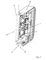
figure 1 est une vue en coupe d'un appareil électrique selon l'invention, la manette d'actionnement ayant été ôtée ; - la
figure 2 est une vue partielle en coupe d'un couvercle d'appareil électrique selon l'invention, avec manette et un moyen de fixation ; - la
figure 3 est une vue arrière d'un enjoliveur d'un appareil selon l'invention, avec une manette ; - la
figure 4 montre un élément d'enjoliveur, sous la forme d'une base pour manette d'interrupteur ; - la
figure 5 est une coupe d'un appareil selon l'invention, destiné à être monté encastré, et - la
figure 6 montre une plaque.
- the
figure 1 is a sectional view of an electrical apparatus according to the invention, the actuating lever having been removed; - the
figure 2 is a partial sectional view of an electric device cover according to the invention, with handle and a fixing means; - the
figure 3 is a rear view of a hubcap of an apparatus according to the invention, with a joystick; - the
figure 4 shows a hubcap element, in the form of a base for a switch handle; - the
figure 5 is a section of an apparatus according to the invention, intended to be mounted flush, and - the
figure 6 shows a plaque.
L'invention a donc pour objet un appareil électrique 1 destiné à être monté en saillie contre ou encastré dans une paroi, comprenant au moins un bloc fonctionnel électrique, du type bloc de commutation, un élément de montage 4 pour le montage à la paroi et la fixation dudit au moins un bloc fonctionnel, tel qu'une boîte pour un montage en saillie ou un support plat pour un montage encastré, et un couvercle 5, placé sur l'élément de montage 4,
le couvercle 5 comprenant, d'une part, une plaque 20 présentant au moins une ouverture 31, et, d'autre part, un enjoliveur 21, compatible avec le au moins un bloc fonctionnel, placé dans ladite au moins une ouverture 31, et comprenant une base 30 et une manette 28,
la base 30 présentant un passage 2 pour des plots 3 que porte la manette 28 et qui sont destinés à agir sur le au moins un bloc fonctionnel, ledit passage 2 étant clos par une membrane 8 élastique portée par ladite base 30 et traversée par lesdits plots 3. L'invention est particulièrement avantageuse dans le cas où le bloc fonctionnel est un bloc de commutation, pour interrupteur, mais elle peut aussi s'appliquer à des blocs fonctionnels de transmission, comme pour un socle électrique ou à d'autres types d'appareils électriques comme une radio, un élément de commande domotique, une signalisation lumineuse, etc.The invention therefore relates to an electrical apparatus 1 intended to be mounted projecting against or embedded in a wall, comprising at least one electrical function block, of the switching block type, a
the
the
Dans des modes de réalisation particuliers, dans lesquels l'appareil électrique 1 doit répondre à des normes d'étanchéité particulières, ce dernier comprend un joint d'interface 26, entre l'élément de montage 4 et le couvercle 5, au moins un joint interne 27, entre la plaque 20 et le au moins un enjoliveur 21, et notamment aussi un joint arrière 25, au niveau de la face de l'élément de montage destinée à être en contact avec la paroi. Un joint interne 27 est prévu pour chaque enjoliveur 21, le cas échéant. Selon une caractéristique additionnelle possible, permettant notamment de réduire le nombre de pièces, mais contribuant aussi à améliorer l'étanchéité, le joint d'interface 26 et le au moins un joint interne 27 forment une seule pièce, notamment surmoulée sur la plaque 20. L'avantage de recourir à du surmoulage est, le cas échéant, une bien meilleure étanchéité ainsi qu'une simplification de la fabrication. Dans le cas où l'appareil électrique 1 comprend plusieurs enjoliveurs 21, et donc autant de joints internes 27, ils sont donc tous d'une seule pièce avec le joint d'interface 26. Le recours à une seule pièce pour les différents joints présente aussi l'avantage, si elle n'est pas surmoulée mais simplement posée, de simplifier la fabrication.In particular embodiments, in which the electrical apparatus 1 must meet particular sealing standards, the latter comprises an
Selon l'invention, l'appareil électrique 1 présente au moins un moyen de fixation 6 de l'enjoliveur 21 à l'élément de montage 4, la plaque 20 étant maintenue entre le au moins un enjoliveur 21 et l'élément de montage 4. Le au moins un moyen de fixation 6 fixe donc la plaque 20 directement à l'élément de montage 4. Il peut consister essentiellement, par exemple, en une vis, un moyen d'encliquetage, un insert à interposer entre le couvercle et une vis y débouchant, ancrée dans l'élément de montage 4, ou un verrou, sous la forme d'une tige pivotante autour de son axe principal, perpendiculaire au mur de montage, entre une position libre et une position verrouillée. Le moyen de fixation 6 maintient mécaniquement le couvercle 5 à l'élément de montage 4, et est préférentiellement déverrouillable, afin de pouvoir démonter le couvercle 5 et accéder au bloc fonctionnel.According to the invention, the electrical apparatus 1 has at least one fastening means 6 of the
L'appareil électrique 1 est donc formé, dans le cas d'un interrupteur, d'une superposition d'un élément de montage 4, d'une plaque 20, d'une base 30 et d'une manette 28, ces trois derniers formant le couvercle 5. Ces éléments sont successivement en appui l'un contre l'autre, et l'enjoliveur 21, essentiellement formé d'une base 30 et d'une manette 28, est directement fixé à l'élément de montage 4 par au moins un moyen de fixation 6. La plaque 20 est donc prise entre, d'une part, l'élément de montage 4, et, d'autre part, l'enjoliveur 21 qui est ancré audit élément de montage 4 grâce à l'au moins un moyen de fixation 6.The electrical apparatus 1 is thus formed, in the case of a switch, of a superposition of a
La manette 28 est, quant à elle, fixée directement à la base 30, en tant qu'élément de l'enjoliveur 21. Elle est généralement encliquetée sur la base 30 au niveau des plots de la base 30 servant à son pivotement.The
Le fait que la plaque 20 soit prise entre, d'une part, l'élément de montage 4, et, d'autre part, l'enjoliveur 21 fixé à l'élément de montage 4 par au moins un moyen de fixation 6, permet de garantir un bon maintien de tout le couvercle 5 à l'élément de montage 4, mais aussi d'assurer la compression des joints entre la plaque 20, aisément commune à différents appareils d'une même gamme, et, d'une part, l'élément de montage 4, à savoir un joint d'interface 26, ou, d'autre part, l'enjoliveur 21, à savoir au moins un joint interne 27.The fact that the
La manette 28 présente, au niveau de sa face arrière, des plots 3, sous forme de nervure allongée, qui agissent sur le bloc fonctionnel de commutation de sorte à en faire commuter les contacts. La base 30, sous forme d'une pièce plastique rigide, présente donc un passage 2 de dimensions suffisamment grandes pour que le mouvement des plots 3 ne soit pas gêné par la matière constitutive rigide de la base 30. Les plots 3, lors de l'actionnement de la manette 28, se déplacent donc dans le passage 2 de la base 30, ce dernier formant une découpe prévue dans un capot rigide que forme la base 30.The
Le passage 2 est ainsi suffisamment grand pour que les plots 3 ne soient jamais gênés par la matière constitutive rigide de la base 30. Afin d'étanchéifier le passage 2, ce dernier est recouvert d'une membrane 8 élastique. Cette dernière est traversée par les plots 3 au niveau d'orifices suffisamment petits pour ne pas créer d'espace nuisant à l'étanchéité autour du plot 3, et suffisamment élastique pour se déformer en suivant le mouvement desdits plots 3 lors du mouvement de la manette 28. La membrane 8, recouvrant le passage 2 porte donc des orifices au niveau desquels elle est traversée par les plots 3. Compte tenu de l'élasticité de la membrane 8, ces orifices pour plot 3 peuvent aisément suivre le mouvement des plots 3, et la membrane 8 garantit donc l'étanchéité du passage 2, malgré la présence des plots 3 sous forme d'éléments déplaçables.The
Selon une caractéristique additionnelle possible, permettant de masquer le au moins un moyen de fixation 6 sous la manette 30, le au moins un moyen de fixation 6 fixe la base 30 à l'élément de montage 4, la plaque 20 étant maintenue entre ladite base 30 et ledit élément de montage 4. Le moyen de fixation 6 peut en effet être une vis, ancrée par son filetage dans l'élément de montage 4 et dont la tête maintient le couvercle 5, et plus précisément la base 30 ou une autre partie de l'enjoliveur 21. La tête de la vis est alors sous la manette 28, et n'est donc plus visible. Le moyen de fixation 6 peut alternativement comprendre un insert, une clé quart de tour, qui alors placé ou placée sous la manette 28. Comme la manette 28 recouvre une grande partie de la base 30, le moyen de fixation 6 est invisible dès lors qu'il se trouve sous ladite manette 28.According to an additional possible feature, making it possible to mask the at least one fastening means 6 under the
Selon une caractéristique additionnelle possible, permettant une installation avec des outils classiques, le au moins un moyen de fixation 6 est actionnable à l'aide d'un outil plat du type tournevis et comprend donc, à cette effet, une rainure adaptée. Le moyen de fixation 6 est préférentiellement actionnable depuis la face avant de l'appareil électrique 1, au niveau du couvercle 5. Il présente donc une rainure ou un jeu de rainure qui permet de créer, à l'aide d'un tournevis ou d'un autre outil plat, le mouvement permettant au moyen de fixation 6 de passer de la position verrouillée, dans laquelle il maintient le couvercle 5 contre l'élément de montage 4, à la position déverrouillée, et inversement.According to an additional possible feature, allowing installation with conventional tools, the at least one fastening means 6 is operable using a flat tool of the screwdriver type and therefore comprises, for this purpose, a suitable groove. The
Selon une caractéristique additionnelle possible, permettant de différencier la fixation du couvercle 5 à l'élément de montage 4 d'autres fixations, par exemple la fixation de l'élément de montage 4 dans un mur, ou encore la fixation du bloc fonctionnel dans l'élément de montage 4, le au moins un moyen de fixation 6 passe d'une position de verrouillage, dans laquelle il fixe le au moins un enjoliveur 21 à l'élément de montage 4, à une position libre, dans laquelle il ne fixe pas le au moins un enjoliveur 21 à l'élément de montage 4, avec une rotation d'une portion de tour, c'est-à-dire une rotation de moins d'un tour. Comme la fixation du couvercle 5, et, plus particulièrement de l'enjoliveur 21, notamment de la base 30, à l'élément de montage 4 dépend directement de la tenue obtenue par le moyen de fixation 6, il est important de différencier cette fixation des autres fixations de l'appareil électrique 1, notamment la fixation mécanique de l'élément de montage 4 au mur, car cette dernière fixation doit être la plus rigide possible. Concernant la fixation du couvercle 5, comme elle pour effet de comprimer des joints d'étanchéité, il pourrait être préjudiciable de la serrer de trop, par exemple en allant jusqu'à écraser complètement les joints et en accélérant ainsi leur vieillissement.According to an additional possible feature, to differentiate the fixing of the
Dans le cas d'un moyen de fixation 6 du type visserie, en particulier dès lors que le moyen de fixation 6 présente des rainures qui en permettent l'actionnement avec un outil plat du type tournevis, une confusion peut donc naître. Le recours à un moyen de fixation 6 passant de sa position verrouillée à sa position libre, et inversement, avec un mouvement de rotation d'une amplitude inférieure à un tour, préférentiellement un quart de tour, permet de faire cette distinction, puisque la fixation de l'élément de montage 4 à la paroi est généralement effectué à l'aide de vis qui créent une tenue mécanique augmentant avec l'amplitude de la rotation.In the case of a fixing means 6 of the fastener type, in particular since the fastening means 6 has grooves that allow actuation with a flat tool of the screwdriver type, confusion can arise. The use of a fixing means 6 passing from its locked position to its free position, and vice versa, with a rotational movement of an amplitude less than one turn, preferably a quarter turn, makes it possible to make this distinction, since the fixing from the
Le moyen de fixation 6 est donc préférentiellement verrouillé ou déverrouillée en réalisant un mouvement d'un quart de tour. Des principes tels que les verrous à quart de tour ou à demi tour sont donc particulièrement pertinents.The fastening means 6 is therefore preferably locked or unlocked by making a movement of a quarter turn. Principles such as quarter-turn or half-turn locks are therefore particularly relevant.
Dans des modes de réalisation particuliers, le mouvement de rotation se fait autour d'un axe perpendiculaire au plan du couvercle 5, ce qui correspond à un mouvement de rotation du même type que celui classiquement utilisé pour la fixation de l'élément de montage 4 au mur.In particular embodiments, the rotational movement is around an axis perpendicular to the plane of the
Dans des modes de réalisation particuliers, le mouvement de rotation se fait autour d'un axe parallèle au plan du couvercle 5, ce qui permet d'éviter toute confusion entre la fixation du couvercle 5 à l'élément de montage 4 de toute autre fixation. Il est en effet important de ne pas confondre la fixation du couvercle 5, qui a un impact sur l'étanchéité et doit donc être traitée de façon particulière, des autres fixations. Cela peut particulièrement correspondre à un insert, qui, afin de verrouiller le moyen de fixation 6, viendrait être glissé entre, d'une part, le couvercle 5, et, plus précisément, l'enjoliveur 21, au niveau d'une surface d'appui, et, d'autre part, la tête d'une vis ancrée dans l'élément de montage 4 et débouchant au-delà de ladite surface d'appui de l'insert dans le couvercle 5.In particular embodiments, the rotational movement is around an axis parallel to the plane of the
Selon une caractéristique additionnelle possible, permettant de réduire les coûts tout en conservant un bon maintien du couvercle 5 sur l'élément de montage 4 ainsi qu'une bonne étanchéité, le au moins un enjoliveur 21 est maintenu par deux moyens de fixation 6, disposés à proximité de deux bords opposés dudit au moins un enjoliveur 21 et décalés l'un par rapport à l'autre, l'appareil électrique 1 comprenant, en outre, deux moyens d'accrochage 22 dudit au moins un enjoliveur 21 à la plaque 20, disposés symétriquement aux deux moyens de fixation 6, et consistant essentiellement chacun en une patte munie de crochets, qui s'étend à partir dudit enjoliveur 21, destinée à venir s'accrocher dans un trou prévu dans la plaque 20.According to an additional feature possible, to reduce costs while maintaining a good retention of the
Bien entendu, l'invention n'est pas limitée au mode de réalisation décrit et représenté aux dessins annexés. Des modifications restent possibles, notamment du point de vue de la constitution des divers éléments, par combinaison des caractéristiques décrites ci-dessus, ou par substitution d'équivalents techniques, sans sortir pour autant du domaine de protection de l'invention.Of course, the invention is not limited to the embodiment described and shown in the accompanying drawings. Modifications are possible, particularly from the point of view of the constitution of the various elements, by combining the features described above, or by substitution of technical equivalents, without departing from the scope of the invention.
Claims (9)
le couvercle (5) comprenant, d'une part, une plaque (20) présentant au moins une ouverture (31), et, d'autre part, un enjoliveur (21), compatible avec le au moins un bloc fonctionnel, placé dans ladite au moins une ouverture (31), et comprenant une base (30) et une manette (28),
la base (30) présentant un passage (2) pour des plots (3) que porte la manette (28) et qui sont destinés à agir sur le au moins un bloc fonctionnel, ledit passage (2) étant clos par une membrane (8) élastique portée par ladite base (30) et traversée par lesdits plots (3)
appareil électrique (1) caractérisé en ce qu'
il présente au moins un moyen de fixation (6) de l'enjoliveur (21) à l'élément de montage (4), la plaque (20) étant maintenue entre le au moins un enjoliveur (21) et l'élément de montage (4).Electrical apparatus (1) intended to be surface-mounted against or recessed into a wall, comprising at least one electrical function block, of the switching block type, a mounting element (4) for mounting to the wall and fixing of said minus a functional block, such as a box for surface mounting or a flat support for flush mounting, and a cover (5), placed on the mounting element (4),
the cover (5) comprising, on the one hand, a plate (20) having at least one opening (31), and, on the other hand, a hubcap (21), compatible with the at least one functional block, placed in said at least one opening (31), and comprising a base (30) and a handle (28),
the base (30) having a passage (2) for studs (3) which the handle (28) carries and which are intended to act on the at least one functional block, said passage (2) being closed by a membrane (8) ) elastic carried by said base (30) and traversed by said pads (3)
electrical apparatus (1) characterized in that
it has at least one means (6) for attaching the trim (21) to the mounting element (4), the plate (20) being held between the at least one trim (21) and the mounting element (4).
Priority Applications (3)
| Application Number | Priority Date | Filing Date | Title |
|---|---|---|---|
| EP12305203.7A EP2632001B1 (en) | 2012-02-22 | 2012-02-22 | Electrical appliance with lid attached in the mounting member |
| ES12305203.7T ES2501092T3 (en) | 2012-02-22 | 2012-02-22 | Electric appliance with cover fixed on the mounting element |
| PT123052037T PT2632001E (en) | 2012-02-22 | 2012-02-22 | Electrical appliance with lid attached in the mounting member |
Applications Claiming Priority (1)
| Application Number | Priority Date | Filing Date | Title |
|---|---|---|---|
| EP12305203.7A EP2632001B1 (en) | 2012-02-22 | 2012-02-22 | Electrical appliance with lid attached in the mounting member |
Publications (2)
| Publication Number | Publication Date |
|---|---|
| EP2632001A1 true EP2632001A1 (en) | 2013-08-28 |
| EP2632001B1 EP2632001B1 (en) | 2014-06-18 |
Family
ID=45999734
Family Applications (1)
| Application Number | Title | Priority Date | Filing Date |
|---|---|---|---|
| EP12305203.7A Active EP2632001B1 (en) | 2012-02-22 | 2012-02-22 | Electrical appliance with lid attached in the mounting member |
Country Status (3)
| Country | Link |
|---|---|
| EP (1) | EP2632001B1 (en) |
| ES (1) | ES2501092T3 (en) |
| PT (1) | PT2632001E (en) |
Cited By (2)
| Publication number | Priority date | Publication date | Assignee | Title |
|---|---|---|---|---|
| EP3767764A1 (en) * | 2019-07-16 | 2021-01-20 | Niko NV | Mounting system for electric or electronic device |
| CN113015361A (en) * | 2019-12-20 | 2021-06-22 | 勒格朗法国公司 | Electrical box and associated electrical equipment |
Citations (2)
| Publication number | Priority date | Publication date | Assignee | Title |
|---|---|---|---|---|
| EP1860748A1 (en) | 2006-05-22 | 2007-11-28 | Legrand France | Watertight electrical equipment to be disposed projecting or embedded in a wall |
| CH696899A5 (en) * | 2004-04-05 | 2008-01-15 | Abb Schweiz Ag | Front plate fastener for detachable and tool less fastening of front plate on fastening plate of electrical switch or tactile sensor, has front plate that has locking spring with locking unit, which are distributed over locking length |
-
2012
- 2012-02-22 ES ES12305203.7T patent/ES2501092T3/en active Active
- 2012-02-22 PT PT123052037T patent/PT2632001E/en unknown
- 2012-02-22 EP EP12305203.7A patent/EP2632001B1/en active Active
Patent Citations (2)
| Publication number | Priority date | Publication date | Assignee | Title |
|---|---|---|---|---|
| CH696899A5 (en) * | 2004-04-05 | 2008-01-15 | Abb Schweiz Ag | Front plate fastener for detachable and tool less fastening of front plate on fastening plate of electrical switch or tactile sensor, has front plate that has locking spring with locking unit, which are distributed over locking length |
| EP1860748A1 (en) | 2006-05-22 | 2007-11-28 | Legrand France | Watertight electrical equipment to be disposed projecting or embedded in a wall |
Cited By (6)
| Publication number | Priority date | Publication date | Assignee | Title |
|---|---|---|---|---|
| EP3767764A1 (en) * | 2019-07-16 | 2021-01-20 | Niko NV | Mounting system for electric or electronic device |
| BE1027430B1 (en) * | 2019-07-16 | 2021-02-15 | Niko Nv | MOUNTING SYSTEM FOR AN ELECTRICAL OR ELECTRONIC DEVICE |
| CN113015361A (en) * | 2019-12-20 | 2021-06-22 | 勒格朗法国公司 | Electrical box and associated electrical equipment |
| EP3840151A1 (en) * | 2019-12-20 | 2021-06-23 | Legrand France | Electrical box and associated electrical switchgear |
| FR3105559A1 (en) * | 2019-12-20 | 2021-06-25 | Legrand France | Electrical box and associated electrical equipment |
| CN113015361B (en) * | 2019-12-20 | 2022-08-02 | 勒格朗法国公司 | Electrical box and associated electrical equipment |
Also Published As
| Publication number | Publication date |
|---|---|
| ES2501092T3 (en) | 2014-10-01 |
| PT2632001E (en) | 2014-09-22 |
| EP2632001B1 (en) | 2014-06-18 |
Similar Documents
| Publication | Publication Date | Title |
|---|---|---|
| FR3042918A1 (en) | ELECTRICAL BOX INSERTED IN PARTITIONS OF DIFFERENT THICKNESSES | |
| EP1675236A1 (en) | Electrical apparatus support | |
| EP2632001B1 (en) | Electrical appliance with lid attached in the mounting member | |
| EP3172750B1 (en) | Trim for electric switch and electric switch with such trim | |
| EP1675235B1 (en) | Cluster electrical apparatus holder for horizontal and vertical mounting | |
| EP1149447B1 (en) | Apparatus support, in particular for electrical apparatus, and box comprising such an apparatus support | |
| EP2097960B1 (en) | Electric equipment carrier | |
| EP1087075A1 (en) | Permanent anchoring device | |
| EP2795023A1 (en) | Strike plate for the closing lock of a movable panel for a vehicle, in particular for a motor vehicle | |
| FR2999024A1 (en) | Electrical apparatus e.g. plug, has side extension including lower edge fixed to support, and mechanism attached to side extension and partially accommodated in inner space delimited by contour of side extension | |
| EP1675233A1 (en) | Electrical apparatus holder with all directions connecting means to a similar type holder | |
| FR2709614A1 (en) | Fixing device for electrical apparatus | |
| EP2661379B1 (en) | Device for positioning the window of a side door of a vehicle relative to an external control for opening said door | |
| CH712040A2 (en) | Clasp folding for bracelet. | |
| EP2632002B1 (en) | Sealed electrical appliance with buffer element | |
| FR2930685A1 (en) | ELECTRICAL EQUIPMENT TO BE REPORTED ON A RECESS BOX. | |
| FR2956259A1 (en) | Scorching accessory for fixing of support of fixing equipment of switchgear to alveolar wall, has upper nut screwed on threaded body of fixing screw between operating head of fixing screw and main wall of fixing claw | |
| FR2799805A1 (en) | Wall anchor for safety fitment such as ladder or platform has spacer bush under head to receive coupling member on fitment | |
| EP2824785B1 (en) | Hinged assembly of a housing for electrical equipment and floor box including such an assembly | |
| CA2914127A1 (en) | Device for coupling two half-cylinders | |
| EP1744426B1 (en) | Electrical box comprising two elements fixed together by means of a toothed strap | |
| EP0225222B1 (en) | Electrical apparatus with improved assembly | |
| FR3064011A1 (en) | PAVEMENT LOOK COMPRISING A LATCH | |
| FR2769124A1 (en) | HOUSING FOR ELECTRICAL EQUIPMENT | |
| FR2774821A1 (en) | LOCK FOR MOBILE PANEL, PARTICULARLY FOR ELECTRICAL ENCLOSURE PLASTRON, AND CORRESPONDING MOBILE PANEL |
Legal Events
| Date | Code | Title | Description |
|---|---|---|---|
| PUAI | Public reference made under article 153(3) epc to a published international application that has entered the european phase |
Free format text: ORIGINAL CODE: 0009012 |
|
| AK | Designated contracting states |
Kind code of ref document: A1 Designated state(s): AL AT BE BG CH CY CZ DE DK EE ES FI FR GB GR HR HU IE IS IT LI LT LU LV MC MK MT NL NO PL PT RO RS SE SI SK SM TR |
|
| AX | Request for extension of the european patent |
Extension state: BA ME |
|
| 17P | Request for examination filed |
Effective date: 20131030 |
|
| RBV | Designated contracting states (corrected) |
Designated state(s): AL AT BE BG CH CY CZ DE DK EE ES FI FR GB GR HR HU IE IS IT LI LT LU LV MC MK MT NL NO PL PT RO RS SE SI SK SM TR |
|
| GRAP | Despatch of communication of intention to grant a patent |
Free format text: ORIGINAL CODE: EPIDOSNIGR1 |
|
| RIC1 | Information provided on ipc code assigned before grant |
Ipc: H02G 3/08 20060101AFI20131209BHEP Ipc: H02G 3/14 20060101ALI20131209BHEP |
|
| INTG | Intention to grant announced |
Effective date: 20140109 |
|
| GRAS | Grant fee paid |
Free format text: ORIGINAL CODE: EPIDOSNIGR3 |
|
| GRAA | (expected) grant |
Free format text: ORIGINAL CODE: 0009210 |
|
| AK | Designated contracting states |
Kind code of ref document: B1 Designated state(s): AL AT BE BG CH CY CZ DE DK EE ES FI FR GB GR HR HU IE IS IT LI LT LU LV MC MK MT NL NO PL PT RO RS SE SI SK SM TR |
|
| REG | Reference to a national code |
Ref country code: GB Ref legal event code: FG4D Free format text: NOT ENGLISH |
|
| REG | Reference to a national code |
Ref country code: CH Ref legal event code: EP |
|
| REG | Reference to a national code |
Ref country code: AT Ref legal event code: REF Ref document number: 673838 Country of ref document: AT Kind code of ref document: T Effective date: 20140715 |
|
| REG | Reference to a national code |
Ref country code: IE Ref legal event code: FG4D Free format text: LANGUAGE OF EP DOCUMENT: FRENCH |
|
| REG | Reference to a national code |
Ref country code: DE Ref legal event code: R096 Ref document number: 602012002154 Country of ref document: DE Effective date: 20140731 |
|
| REG | Reference to a national code |
Ref country code: CH Ref legal event code: NV Representative=s name: DR. GRAF AND PARTNER AG INTELLECTUAL PROPERTY, CH |
|
| REG | Reference to a national code |
Ref country code: PT Ref legal event code: SC4A Free format text: AVAILABILITY OF NATIONAL TRANSLATION Effective date: 20140915 |
|
| REG | Reference to a national code |
Ref country code: ES Ref legal event code: FG2A Ref document number: 2501092 Country of ref document: ES Kind code of ref document: T3 Effective date: 20141001 |
|
| PG25 | Lapsed in a contracting state [announced via postgrant information from national office to epo] |
Ref country code: LT Free format text: LAPSE BECAUSE OF FAILURE TO SUBMIT A TRANSLATION OF THE DESCRIPTION OR TO PAY THE FEE WITHIN THE PRESCRIBED TIME-LIMIT Effective date: 20140618 Ref country code: CY Free format text: LAPSE BECAUSE OF FAILURE TO SUBMIT A TRANSLATION OF THE DESCRIPTION OR TO PAY THE FEE WITHIN THE PRESCRIBED TIME-LIMIT Effective date: 20140618 Ref country code: NO Free format text: LAPSE BECAUSE OF FAILURE TO SUBMIT A TRANSLATION OF THE DESCRIPTION OR TO PAY THE FEE WITHIN THE PRESCRIBED TIME-LIMIT Effective date: 20140918 Ref country code: GR Free format text: LAPSE BECAUSE OF FAILURE TO SUBMIT A TRANSLATION OF THE DESCRIPTION OR TO PAY THE FEE WITHIN THE PRESCRIBED TIME-LIMIT Effective date: 20140919 Ref country code: FI Free format text: LAPSE BECAUSE OF FAILURE TO SUBMIT A TRANSLATION OF THE DESCRIPTION OR TO PAY THE FEE WITHIN THE PRESCRIBED TIME-LIMIT Effective date: 20140618 |
|
| REG | Reference to a national code |
Ref country code: NL Ref legal event code: VDEP Effective date: 20140618 |
|
| REG | Reference to a national code |
Ref country code: AT Ref legal event code: MK05 Ref document number: 673838 Country of ref document: AT Kind code of ref document: T Effective date: 20140618 |
|
| REG | Reference to a national code |
Ref country code: LT Ref legal event code: MG4D |
|
| PG25 | Lapsed in a contracting state [announced via postgrant information from national office to epo] |
Ref country code: LV Free format text: LAPSE BECAUSE OF FAILURE TO SUBMIT A TRANSLATION OF THE DESCRIPTION OR TO PAY THE FEE WITHIN THE PRESCRIBED TIME-LIMIT Effective date: 20140618 Ref country code: RS Free format text: LAPSE BECAUSE OF FAILURE TO SUBMIT A TRANSLATION OF THE DESCRIPTION OR TO PAY THE FEE WITHIN THE PRESCRIBED TIME-LIMIT Effective date: 20140618 Ref country code: SE Free format text: LAPSE BECAUSE OF FAILURE TO SUBMIT A TRANSLATION OF THE DESCRIPTION OR TO PAY THE FEE WITHIN THE PRESCRIBED TIME-LIMIT Effective date: 20140618 Ref country code: HR Free format text: LAPSE BECAUSE OF FAILURE TO SUBMIT A TRANSLATION OF THE DESCRIPTION OR TO PAY THE FEE WITHIN THE PRESCRIBED TIME-LIMIT Effective date: 20140618 |
|
| PG25 | Lapsed in a contracting state [announced via postgrant information from national office to epo] |
Ref country code: CZ Free format text: LAPSE BECAUSE OF FAILURE TO SUBMIT A TRANSLATION OF THE DESCRIPTION OR TO PAY THE FEE WITHIN THE PRESCRIBED TIME-LIMIT Effective date: 20140618 Ref country code: EE Free format text: LAPSE BECAUSE OF FAILURE TO SUBMIT A TRANSLATION OF THE DESCRIPTION OR TO PAY THE FEE WITHIN THE PRESCRIBED TIME-LIMIT Effective date: 20140618 Ref country code: RO Free format text: LAPSE BECAUSE OF FAILURE TO SUBMIT A TRANSLATION OF THE DESCRIPTION OR TO PAY THE FEE WITHIN THE PRESCRIBED TIME-LIMIT Effective date: 20140618 Ref country code: SK Free format text: LAPSE BECAUSE OF FAILURE TO SUBMIT A TRANSLATION OF THE DESCRIPTION OR TO PAY THE FEE WITHIN THE PRESCRIBED TIME-LIMIT Effective date: 20140618 |
|
| PG25 | Lapsed in a contracting state [announced via postgrant information from national office to epo] |
Ref country code: IS Free format text: LAPSE BECAUSE OF FAILURE TO SUBMIT A TRANSLATION OF THE DESCRIPTION OR TO PAY THE FEE WITHIN THE PRESCRIBED TIME-LIMIT Effective date: 20141018 Ref country code: PL Free format text: LAPSE BECAUSE OF FAILURE TO SUBMIT A TRANSLATION OF THE DESCRIPTION OR TO PAY THE FEE WITHIN THE PRESCRIBED TIME-LIMIT Effective date: 20140618 Ref country code: AT Free format text: LAPSE BECAUSE OF FAILURE TO SUBMIT A TRANSLATION OF THE DESCRIPTION OR TO PAY THE FEE WITHIN THE PRESCRIBED TIME-LIMIT Effective date: 20140618 Ref country code: NL Free format text: LAPSE BECAUSE OF FAILURE TO SUBMIT A TRANSLATION OF THE DESCRIPTION OR TO PAY THE FEE WITHIN THE PRESCRIBED TIME-LIMIT Effective date: 20140618 |
|
| REG | Reference to a national code |
Ref country code: DE Ref legal event code: R097 Ref document number: 602012002154 Country of ref document: DE |
|
| PLBE | No opposition filed within time limit |
Free format text: ORIGINAL CODE: 0009261 |
|
| STAA | Information on the status of an ep patent application or granted ep patent |
Free format text: STATUS: NO OPPOSITION FILED WITHIN TIME LIMIT |
|
| PG25 | Lapsed in a contracting state [announced via postgrant information from national office to epo] |
Ref country code: DK Free format text: LAPSE BECAUSE OF FAILURE TO SUBMIT A TRANSLATION OF THE DESCRIPTION OR TO PAY THE FEE WITHIN THE PRESCRIBED TIME-LIMIT Effective date: 20140618 |
|
| 26N | No opposition filed |
Effective date: 20150319 |
|
| PG25 | Lapsed in a contracting state [announced via postgrant information from national office to epo] |
Ref country code: SI Free format text: LAPSE BECAUSE OF FAILURE TO SUBMIT A TRANSLATION OF THE DESCRIPTION OR TO PAY THE FEE WITHIN THE PRESCRIBED TIME-LIMIT Effective date: 20140618 |
|
| REG | Reference to a national code |
Ref country code: FR Ref legal event code: PLFP Year of fee payment: 5 |
|
| PG25 | Lapsed in a contracting state [announced via postgrant information from national office to epo] |
Ref country code: MT Free format text: LAPSE BECAUSE OF FAILURE TO SUBMIT A TRANSLATION OF THE DESCRIPTION OR TO PAY THE FEE WITHIN THE PRESCRIBED TIME-LIMIT Effective date: 20140618 |
|
| REG | Reference to a national code |
Ref country code: FR Ref legal event code: PLFP Year of fee payment: 6 |
|
| PG25 | Lapsed in a contracting state [announced via postgrant information from national office to epo] |
Ref country code: BG Free format text: LAPSE BECAUSE OF FAILURE TO SUBMIT A TRANSLATION OF THE DESCRIPTION OR TO PAY THE FEE WITHIN THE PRESCRIBED TIME-LIMIT Effective date: 20140618 Ref country code: SM Free format text: LAPSE BECAUSE OF FAILURE TO SUBMIT A TRANSLATION OF THE DESCRIPTION OR TO PAY THE FEE WITHIN THE PRESCRIBED TIME-LIMIT Effective date: 20140618 Ref country code: HU Free format text: LAPSE BECAUSE OF FAILURE TO SUBMIT A TRANSLATION OF THE DESCRIPTION OR TO PAY THE FEE WITHIN THE PRESCRIBED TIME-LIMIT; INVALID AB INITIO Effective date: 20120222 |
|
| REG | Reference to a national code |
Ref country code: FR Ref legal event code: PLFP Year of fee payment: 7 |
|
| PG25 | Lapsed in a contracting state [announced via postgrant information from national office to epo] |
Ref country code: MK Free format text: LAPSE BECAUSE OF FAILURE TO SUBMIT A TRANSLATION OF THE DESCRIPTION OR TO PAY THE FEE WITHIN THE PRESCRIBED TIME-LIMIT Effective date: 20140618 |
|
| PG25 | Lapsed in a contracting state [announced via postgrant information from national office to epo] |
Ref country code: AL Free format text: LAPSE BECAUSE OF FAILURE TO SUBMIT A TRANSLATION OF THE DESCRIPTION OR TO PAY THE FEE WITHIN THE PRESCRIBED TIME-LIMIT Effective date: 20140618 |
|
| PGFP | Annual fee paid to national office [announced via postgrant information from national office to epo] |
Ref country code: MC Payment date: 20230202 Year of fee payment: 12 Ref country code: LU Payment date: 20230227 Year of fee payment: 12 Ref country code: IE Payment date: 20230227 Year of fee payment: 12 Ref country code: FR Payment date: 20230223 Year of fee payment: 12 Ref country code: ES Payment date: 20230301 Year of fee payment: 12 Ref country code: CH Payment date: 20230307 Year of fee payment: 12 |
|
| PGFP | Annual fee paid to national office [announced via postgrant information from national office to epo] |
Ref country code: TR Payment date: 20230214 Year of fee payment: 12 Ref country code: IT Payment date: 20230221 Year of fee payment: 12 Ref country code: BE Payment date: 20230227 Year of fee payment: 12 |
|
| P01 | Opt-out of the competence of the unified patent court (upc) registered |
Effective date: 20230606 |
|
| PGFP | Annual fee paid to national office [announced via postgrant information from national office to epo] |
Ref country code: LU Payment date: 20240227 Year of fee payment: 13 |
|
| PGFP | Annual fee paid to national office [announced via postgrant information from national office to epo] |
Ref country code: IE Payment date: 20240227 Year of fee payment: 13 Ref country code: ES Payment date: 20240301 Year of fee payment: 13 |
|
| PGFP | Annual fee paid to national office [announced via postgrant information from national office to epo] |
Ref country code: MC Payment date: 20240202 Year of fee payment: 13 |
|
| PGFP | Annual fee paid to national office [announced via postgrant information from national office to epo] |
Ref country code: DE Payment date: 20240228 Year of fee payment: 13 Ref country code: CH Payment date: 20240301 Year of fee payment: 13 Ref country code: PT Payment date: 20240214 Year of fee payment: 13 Ref country code: GB Payment date: 20240227 Year of fee payment: 13 |