EP2631918A2 - Method of manufacturing magnet and magnet - Google Patents
Method of manufacturing magnet and magnet Download PDFInfo
- Publication number
- EP2631918A2 EP2631918A2 EP13156391.8A EP13156391A EP2631918A2 EP 2631918 A2 EP2631918 A2 EP 2631918A2 EP 13156391 A EP13156391 A EP 13156391A EP 2631918 A2 EP2631918 A2 EP 2631918A2
- Authority
- EP
- European Patent Office
- Prior art keywords
- material powders
- magnet
- compound
- compact
- oxidation
- Prior art date
- Legal status (The legal status is an assumption and is not a legal conclusion. Google has not performed a legal analysis and makes no representation as to the accuracy of the status listed.)
- Withdrawn
Links
- 238000004519 manufacturing process Methods 0.000 title claims description 19
- 239000000843 powder Substances 0.000 claims abstract description 60
- 239000000463 material Substances 0.000 claims abstract description 58
- 150000001875 compounds Chemical class 0.000 claims abstract description 29
- 230000001590 oxidative effect Effects 0.000 claims abstract description 12
- 229910052761 rare earth metal Inorganic materials 0.000 claims abstract description 8
- 230000006835 compression Effects 0.000 claims abstract description 7
- 238000007906 compression Methods 0.000 claims abstract description 7
- 238000010304 firing Methods 0.000 claims description 19
- 238000010438 heat treatment Methods 0.000 claims description 17
- 238000000354 decomposition reaction Methods 0.000 claims description 9
- 230000004907 flux Effects 0.000 description 9
- 230000007423 decrease Effects 0.000 description 6
- 229910052692 Dysprosium Inorganic materials 0.000 description 5
- QVGXLLKOCUKJST-UHFFFAOYSA-N atomic oxygen Chemical compound [O] QVGXLLKOCUKJST-UHFFFAOYSA-N 0.000 description 5
- KBQHZAAAGSGFKK-UHFFFAOYSA-N dysprosium atom Chemical compound [Dy] KBQHZAAAGSGFKK-UHFFFAOYSA-N 0.000 description 5
- 239000001301 oxygen Substances 0.000 description 5
- 229910052760 oxygen Inorganic materials 0.000 description 5
- 229910000920 Fe16N2 Inorganic materials 0.000 description 4
- 239000007767 bonding agent Substances 0.000 description 4
- 239000007789 gas Substances 0.000 description 4
- 238000000034 method Methods 0.000 description 3
- 229910001172 neodymium magnet Inorganic materials 0.000 description 3
- 238000001000 micrograph Methods 0.000 description 2
- 239000002245 particle Substances 0.000 description 2
- 238000005245 sintering Methods 0.000 description 2
- 239000000853 adhesive Substances 0.000 description 1
- 238000005452 bending Methods 0.000 description 1
- 230000015572 biosynthetic process Effects 0.000 description 1
- 150000002910 rare earth metals Chemical class 0.000 description 1
Images
Classifications
-
- H—ELECTRICITY
- H01—ELECTRIC ELEMENTS
- H01F—MAGNETS; INDUCTANCES; TRANSFORMERS; SELECTION OF MATERIALS FOR THEIR MAGNETIC PROPERTIES
- H01F41/00—Apparatus or processes specially adapted for manufacturing or assembling magnets, inductances or transformers; Apparatus or processes specially adapted for manufacturing materials characterised by their magnetic properties
- H01F41/02—Apparatus or processes specially adapted for manufacturing or assembling magnets, inductances or transformers; Apparatus or processes specially adapted for manufacturing materials characterised by their magnetic properties for manufacturing cores, coils, or magnets
- H01F41/0253—Apparatus or processes specially adapted for manufacturing or assembling magnets, inductances or transformers; Apparatus or processes specially adapted for manufacturing materials characterised by their magnetic properties for manufacturing cores, coils, or magnets for manufacturing permanent magnets
- H01F41/0266—Moulding; Pressing
-
- H—ELECTRICITY
- H01—ELECTRIC ELEMENTS
- H01F—MAGNETS; INDUCTANCES; TRANSFORMERS; SELECTION OF MATERIALS FOR THEIR MAGNETIC PROPERTIES
- H01F1/00—Magnets or magnetic bodies characterised by the magnetic materials therefor; Selection of materials for their magnetic properties
- H01F1/01—Magnets or magnetic bodies characterised by the magnetic materials therefor; Selection of materials for their magnetic properties of inorganic materials
- H01F1/03—Magnets or magnetic bodies characterised by the magnetic materials therefor; Selection of materials for their magnetic properties of inorganic materials characterised by their coercivity
- H01F1/032—Magnets or magnetic bodies characterised by the magnetic materials therefor; Selection of materials for their magnetic properties of inorganic materials characterised by their coercivity of hard-magnetic materials
- H01F1/04—Magnets or magnetic bodies characterised by the magnetic materials therefor; Selection of materials for their magnetic properties of inorganic materials characterised by their coercivity of hard-magnetic materials metals or alloys
- H01F1/047—Alloys characterised by their composition
- H01F1/053—Alloys characterised by their composition containing rare earth metals
- H01F1/055—Alloys characterised by their composition containing rare earth metals and magnetic transition metals, e.g. SmCo5
- H01F1/059—Alloys characterised by their composition containing rare earth metals and magnetic transition metals, e.g. SmCo5 and Va elements, e.g. Sm2Fe17N2
- H01F1/0596—Alloys characterised by their composition containing rare earth metals and magnetic transition metals, e.g. SmCo5 and Va elements, e.g. Sm2Fe17N2 of rhombic or rhombohedral Th2Zn17 structure or hexagonal Th2Ni17 structure
-
- C—CHEMISTRY; METALLURGY
- C22—METALLURGY; FERROUS OR NON-FERROUS ALLOYS; TREATMENT OF ALLOYS OR NON-FERROUS METALS
- C22C—ALLOYS
- C22C38/00—Ferrous alloys, e.g. steel alloys
- C22C38/001—Ferrous alloys, e.g. steel alloys containing N
-
- C—CHEMISTRY; METALLURGY
- C22—METALLURGY; FERROUS OR NON-FERROUS ALLOYS; TREATMENT OF ALLOYS OR NON-FERROUS METALS
- C22C—ALLOYS
- C22C38/00—Ferrous alloys, e.g. steel alloys
- C22C38/005—Ferrous alloys, e.g. steel alloys containing rare earths, i.e. Sc, Y, Lanthanides
-
- H—ELECTRICITY
- H01—ELECTRIC ELEMENTS
- H01F—MAGNETS; INDUCTANCES; TRANSFORMERS; SELECTION OF MATERIALS FOR THEIR MAGNETIC PROPERTIES
- H01F1/00—Magnets or magnetic bodies characterised by the magnetic materials therefor; Selection of materials for their magnetic properties
- H01F1/01—Magnets or magnetic bodies characterised by the magnetic materials therefor; Selection of materials for their magnetic properties of inorganic materials
-
- H—ELECTRICITY
- H01—ELECTRIC ELEMENTS
- H01F—MAGNETS; INDUCTANCES; TRANSFORMERS; SELECTION OF MATERIALS FOR THEIR MAGNETIC PROPERTIES
- H01F1/00—Magnets or magnetic bodies characterised by the magnetic materials therefor; Selection of materials for their magnetic properties
- H01F1/01—Magnets or magnetic bodies characterised by the magnetic materials therefor; Selection of materials for their magnetic properties of inorganic materials
- H01F1/03—Magnets or magnetic bodies characterised by the magnetic materials therefor; Selection of materials for their magnetic properties of inorganic materials characterised by their coercivity
- H01F1/032—Magnets or magnetic bodies characterised by the magnetic materials therefor; Selection of materials for their magnetic properties of inorganic materials characterised by their coercivity of hard-magnetic materials
- H01F1/04—Magnets or magnetic bodies characterised by the magnetic materials therefor; Selection of materials for their magnetic properties of inorganic materials characterised by their coercivity of hard-magnetic materials metals or alloys
- H01F1/06—Magnets or magnetic bodies characterised by the magnetic materials therefor; Selection of materials for their magnetic properties of inorganic materials characterised by their coercivity of hard-magnetic materials metals or alloys in the form of particles, e.g. powder
- H01F1/065—Magnets or magnetic bodies characterised by the magnetic materials therefor; Selection of materials for their magnetic properties of inorganic materials characterised by their coercivity of hard-magnetic materials metals or alloys in the form of particles, e.g. powder obtained by a reduction
-
- H—ELECTRICITY
- H01—ELECTRIC ELEMENTS
- H01F—MAGNETS; INDUCTANCES; TRANSFORMERS; SELECTION OF MATERIALS FOR THEIR MAGNETIC PROPERTIES
- H01F1/00—Magnets or magnetic bodies characterised by the magnetic materials therefor; Selection of materials for their magnetic properties
- H01F1/01—Magnets or magnetic bodies characterised by the magnetic materials therefor; Selection of materials for their magnetic properties of inorganic materials
- H01F1/03—Magnets or magnetic bodies characterised by the magnetic materials therefor; Selection of materials for their magnetic properties of inorganic materials characterised by their coercivity
- H01F1/032—Magnets or magnetic bodies characterised by the magnetic materials therefor; Selection of materials for their magnetic properties of inorganic materials characterised by their coercivity of hard-magnetic materials
- H01F1/04—Magnets or magnetic bodies characterised by the magnetic materials therefor; Selection of materials for their magnetic properties of inorganic materials characterised by their coercivity of hard-magnetic materials metals or alloys
- H01F1/06—Magnets or magnetic bodies characterised by the magnetic materials therefor; Selection of materials for their magnetic properties of inorganic materials characterised by their coercivity of hard-magnetic materials metals or alloys in the form of particles, e.g. powder
- H01F1/08—Magnets or magnetic bodies characterised by the magnetic materials therefor; Selection of materials for their magnetic properties of inorganic materials characterised by their coercivity of hard-magnetic materials metals or alloys in the form of particles, e.g. powder pressed, sintered, or bound together
-
- B—PERFORMING OPERATIONS; TRANSPORTING
- B22—CASTING; POWDER METALLURGY
- B22F—WORKING METALLIC POWDER; MANUFACTURE OF ARTICLES FROM METALLIC POWDER; MAKING METALLIC POWDER; APPARATUS OR DEVICES SPECIALLY ADAPTED FOR METALLIC POWDER
- B22F3/00—Manufacture of workpieces or articles from metallic powder characterised by the manner of compacting or sintering; Apparatus specially adapted therefor ; Presses and furnaces
- B22F3/02—Compacting only
-
- B—PERFORMING OPERATIONS; TRANSPORTING
- B22—CASTING; POWDER METALLURGY
- B22F—WORKING METALLIC POWDER; MANUFACTURE OF ARTICLES FROM METALLIC POWDER; MAKING METALLIC POWDER; APPARATUS OR DEVICES SPECIALLY ADAPTED FOR METALLIC POWDER
- B22F3/00—Manufacture of workpieces or articles from metallic powder characterised by the manner of compacting or sintering; Apparatus specially adapted therefor ; Presses and furnaces
- B22F3/10—Sintering only
- B22F3/1003—Use of special medium during sintering, e.g. sintering aid
- B22F3/1007—Atmosphere
Definitions
- the invention relates to a method of manufacturing a magnet, and a magnet.
- Neodymium magnets (Nd-Fe-B magnets) have been used as high performance magnets.
- Dy dysprosium
- Dy which is expensive and rare, is used to manufacture high performance neodymium magnets. Therefore, development of magnets that are manufactured without using dysprosium has been promoted recently.
- Sm-Fe-N magnets that are manufactured without using dysprosium are known.
- the decomposition temperature of a Sm-Fe-N compound is low, it is difficult to subject the Sm-Fe-N compound to high temperature sintering. If the Sm-Fe-N compound is sintered at a temperature equal to or higher than the decomposition temperature, the compound is decomposed. This may cause a possibility that the magnet will not be able to exhibit its performance as a magnet.
- material powders of the compound are bonded by a bonding agent.
- using the bonding agent causes a decrease in the density of the material powders of the magnet, which may be a factor of a decrease in the residual magnetic flux density.
- Japanese Patent Application Publication No. 2005-223263 describes manufacturing a rare earth permanent magnet by forming oxide films on Sm-Fe-N compound powders, forming the compound powders into a compact having predetermined shape through compression preforming performed in a non-oxidative atmosphere, and then consolidating the compact at a temperature of 350°C to 500°C in a non-oxidative atmosphere. In this way, it is possible to manufacture a Sm-Fe-N magnet at a temperature lower than the decomposition temperature.
- oxide films may cause a decrease of the residual magnetic flux density. Accordingly, if an oxide film is formed on the entirety of the outer face of each of the compound powders, the residual magnetic flux density decreases.
- An aspect of the invention relates to a method of manufacturing a magnet, including: a forming step of forming material powders made of a R-Fe-N compound that contains a light rare earth element as R or material powders made of a Fe-N compound into a compact having a predetermined shape through compression forming; and an oxidation-firing step of heating the compact formed of the material powders in an oxidative atmosphere to bond the material powders to each other by oxide films formed on the material powders.
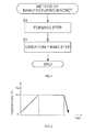
- step S1 forming step
- a R-Fe-N compound that contains a light rare earth element as R, or a Fe-N compound is used as the material powders 10 used to manufacture the magnet.
- Sm is preferably used as the light rare earth element R. That is, Sm 2 Fe 17 N 3 or Fe 16 N 2 is preferably used as the material powders 10 used to manufacture the magnet.
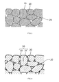
- FIG. 3 is a schematic sectional view showing the microscopic structure of the compact.
- the material powders 10 are not deformed at all or deformed just slightly due to compression. Accordingly, although the material powders 10 are partially contact each other, clearances 20 are formed between the material powders 10.
- the compact is formed in an oxidative atmosphere in order to allow oxidizing gas to enter the clearances 20. Note that, adhesive agents such as a bonding agent are not used in the forming step. Therefore, the bonding strength of the material powders 10 is low.
- the average particle diameter of the material powders 10 is approximately 3 ⁇ m and the compact has a minimum thickness of approximately 2 mm, and a pressure applied to form the compact is approximately 50 MPa. Further, when the material powders 10 made of Fe 16 N 2 are used, manufacturing parameters substantially equal to those for the material powders 10 made of Sm 2 Fe 17 N 3 may be used.
- step S2 oxidation-firing step
- the oxidation-firing step is carried out with the compact placed in a heating furnace in which heating is performed using microwaves, an electric furnace, a plasma furnace, a high-frequency heating furnace, a heating furnace in which heating is performed using an infrared heater or the like.
- the heat treatment process in the oxidation-firing step is as shown in FIG. 2 .
- a heating temperature Tel is set lower than a decomposition temperature Te2 of compound material powders.
- the heating temperature Tel is set lower than 500°C because the decomposition temperature Te2 of the compound is approximately 500°C.
- the heating temperature Tel is set to approximately 200°C. The same applies to the case where the material powders of Fe 16 N 2 are used.
- the oxygen density and the gas pressure of the oxidative atmosphere are not particularly limited as long as the material powders are oxidized.
- the oxygen density and the gas pressure of the oxidative atmosphere may be substantially equal to the oxygen density in the atmospheric air and the atmospheric pressure, respectively.
- the material powders may be heated in an atmosphere of the atmospheric air. Further, by setting the heating temperature Tel to approximately 200°C, oxide films are formed regardless of whether the material powders of Sm 2 Fe 17 N 3 are used or the material powders of Fe 16 N 2 are used.
- FIG. 4 is a schematic sectional view showing the microscopic structure of the compact after the oxidation-firing step.
- exposed faces of the material powders 30 chemically react with oxygen, and as a result, oxide films 32 (as indicated by the bold lines in FIG. 4 ) are formed.
- the oxide films 32 bond adjacent material powders 30 to each other, and accordingly, a sufficient strength of the compact is ensured.
- the material powders 10 are partially contact each other, and the clearances 20 are formed between the material powders 10.
- the oxide films 32 are formed on the material powders at their outer face sides exposed to the clearances 20, and the oxide films 32 bond adjacent material powders 30 to each other. That is, the oxide films 32 are formed on the parts of the material powders 30, which are exposed to the clearances 20, while the parts of the material powders 30, which are not exposed to the clearances 20, are used as a base material 31. Thus, the oxide film 32 is not formed on the entirety of the outer face of each material powder 30.
- the amount of the oxide films 32 is set to the smallest possible amount at which a sufficient bonding strength of the material powders 30 is ensured, it is possible to suppress a decrease in the residual magnetic flux density of the magnet due to formation of the oxide films 32. Therefore, it is possible to manufacture a magnet which is inexpensive and which exhibits a high performance.
- the R-Fe-N compound or the Fe-N compound is used, and accordingly, it is possible to avoid using dysprosium.
- a magnet is manufactured at low cost.
- the R-Fe-N compound and the Fe-N compound each have a low decomposition temperature, it is difficult to apply high temperature sintering.
- the compound is heated at a temperature lower than its decomposition temperature Te2 in the oxidation-firing step, it is possible to prevent the compound from being decomposed.
- Te2 decomposition temperature
- Sm 2 Fe 17 N 3 manufactured by Nichia Corporation and described in Japanese Patent Application Publication No. 2000-104104 was used as the material powders. Specifically, Sm 2 Fe 17 N 3 having an average particle diameter of 3 ⁇ m was used as the material powders.
- the material powders were then pressed in a cold-forming step by a magnetic field orientation press under a pressure of 50 MPa to form a compact having a shape of a rectangular parallelepiped of 10 mm x 30 mm x 2mm. Then, in the oxidation-firing step, the thus formed compact was heated in an atmosphere of the atmospheric air within an electric furnace. In the heat treatment process, the heating temperature Tel was 200°C and the temperature increase rate was 2.25°C / min.
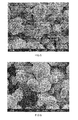
- FIG. 5 a photograph of the outer face of the compact before the oxidation-firing step is as shown in FIG. 5
- a photograph of the outer face of the compact or the magnet after the oxidation-firing step is as shown in FIG. 6 .
- a comparison between FIG. 5 and FIG. 6 indicates that each of the material powders shown in FIG. 5 has an outer face with less unevenness, whereas each of the material powders shown in FIG. 6 has an outer face on which netlike ridges are developed. It is considered that the netlike ridges constitute the oxide films 32. Further, it is understood that the netlike ridges shown in FIG. 6 bond the adjacent material powders to each other. Thus, the material powders 10 are integrally bonded to each other by the oxide films 32.
- the strength of the compact after the oxidation-firing step was evaluated by a bending strength test, and it was found that the strength was 2.0 MPa. Further, the residual magnetic density of the magnet was evaluated with the use of a vibrating sample magnetometer (VSM), and it was found that the residual magnetic flux density was 1.0T. Thus, it was found that it is possible to obtain the magnet having a sufficient strength and a sufficient residual magnetic flux density.
- VSM vibrating sample magnetometer
Landscapes
- Engineering & Computer Science (AREA)
- Chemical & Material Sciences (AREA)
- Power Engineering (AREA)
- Mechanical Engineering (AREA)
- Materials Engineering (AREA)
- Metallurgy (AREA)
- Organic Chemistry (AREA)
- Inorganic Chemistry (AREA)
- Crystallography & Structural Chemistry (AREA)
- Manufacturing & Machinery (AREA)
- Powder Metallurgy (AREA)
- Hard Magnetic Materials (AREA)
- Manufacturing Cores, Coils, And Magnets (AREA)
Abstract
Description
- The invention relates to a method of manufacturing a magnet, and a magnet.
- Neodymium magnets (Nd-Fe-B magnets) have been used as high performance magnets. However, dysprosium (Dy), which is expensive and rare, is used to manufacture high performance neodymium magnets. Therefore, development of magnets that are manufactured without using dysprosium has been promoted recently.
- Sm-Fe-N magnets that are manufactured without using dysprosium are known. However, because the decomposition temperature of a Sm-Fe-N compound is low, it is difficult to subject the Sm-Fe-N compound to high temperature sintering. If the Sm-Fe-N compound is sintered at a temperature equal to or higher than the decomposition temperature, the compound is decomposed. This may cause a possibility that the magnet will not be able to exhibit its performance as a magnet. Thus, material powders of the compound are bonded by a bonding agent. However, using the bonding agent causes a decrease in the density of the material powders of the magnet, which may be a factor of a decrease in the residual magnetic flux density.
- Japanese Patent Application Publication No.
2005-223263 - However, oxide films may cause a decrease of the residual magnetic flux density. Accordingly, if an oxide film is formed on the entirety of the outer face of each of the compound powders, the residual magnetic flux density decreases.
- It is an object of the invention to provide a method of manufacturing a magnet with which a high residual magnetic flux density is obtained, without using dysprosium and without using a bonding agent, and a magnet.
- An aspect of the invention relates to a method of manufacturing a magnet, including: a forming step of forming material powders made of a R-Fe-N compound that contains a light rare earth element as R or material powders made of a Fe-N compound into a compact having a predetermined shape through compression forming; and an oxidation-firing step of heating the compact formed of the material powders in an oxidative atmosphere to bond the material powders to each other by oxide films formed on the material powders.
- The foregoing and further features and advantages of the invention will become apparent from the following description of example embodiments with reference to the accompanying drawings, wherein like numerals are used to represent like elements, and wherein:
-
FIG. 1 is a flowchart for describing a method of manufacturing a magnet according to an embodiment of the invention; -
FIG. 2 is a graph showing a heat treatment process in an oxidation-firing step shown inFIG. 1 ; -
FIG. 3 is a schematic sectional view illustrating the microscopic structure before the oxidation-firing step shown inFIG. 1 ; -
FIG. 4 is a schematic sectional view illustrating the microscopic structure after the oxidation-firing step shown inFIG. 1 ; -
FIG. 5 is a microphotograph (x8000) illustrating an outer face before the oxidation-firing step in the embodiment; and -
FIG. 6 is a microphotograph (x8000) illustrating the outer face after the oxidation-firing step in the embodiment. - Hereinafter, a method of manufacturing a magnet according to an embodiment of the invention will be described with reference to
FIG. 1 to FIG. 4 . As shown inFIG. 1 ,material powders 10 used to manufacture the magnet are formed into a compact having a predetermined shape through compression forming (step S1: forming step). A R-Fe-N compound that contains a light rare earth element as R, or a Fe-N compound is used as thematerial powders 10 used to manufacture the magnet. Sm is preferably used as the light rare earth element R. That is, Sm2Fe17N3 or Fe16N2 is preferably used as thematerial powders 10 used to manufacture the magnet. -
FIG. 3 is a schematic sectional view showing the microscopic structure of the compact. In the compact formed in the forming step, thematerial powders 10 are not deformed at all or deformed just slightly due to compression. Accordingly, although thematerial powders 10 are partially contact each other,clearances 20 are formed between thematerial powders 10. Preferably, the compact is formed in an oxidative atmosphere in order to allow oxidizing gas to enter theclearances 20. Note that, adhesive agents such as a bonding agent are not used in the forming step. Therefore, the bonding strength of thematerial powders 10 is low. - When the
material powders 10 made of, for example, Sm2Fe17N3 are used, the average particle diameter of thematerial powders 10 is approximately 3 µm and the compact has a minimum thickness of approximately 2 mm, and a pressure applied to form the compact is approximately 50 MPa. Further, when thematerial powders 10 made of Fe16N2 are used, manufacturing parameters substantially equal to those for thematerial powders 10 made of Sm2Fe17N3 may be used. - Next, the compact formed in the forming step is heated in an oxidative atmosphere (step S2: oxidation-firing step). The oxidation-firing step is carried out with the compact placed in a heating furnace in which heating is performed using microwaves, an electric furnace, a plasma furnace, a high-frequency heating furnace, a heating furnace in which heating is performed using an infrared heater or the like. The heat treatment process in the oxidation-firing step is as shown in
FIG. 2 . - A heating temperature Tel is set lower than a decomposition temperature Te2 of compound material powders. For example, when the
material powders 10 of Sm2Fe17N3 are used, the heating temperature Tel is set lower than 500°C because the decomposition temperature Te2 of the compound is approximately 500°C. For example, the heating temperature Tel is set to approximately 200°C. The same applies to the case where the material powders of Fe16N2 are used. - Further, the oxygen density and the gas pressure of the oxidative atmosphere are not particularly limited as long as the material powders are oxidized. The oxygen density and the gas pressure of the oxidative atmosphere may be substantially equal to the oxygen density in the atmospheric air and the atmospheric pressure, respectively. Thus, it is not necessary to particularly control the oxygen density and the gas pressure. Accordingly, the material powders may be heated in an atmosphere of the atmospheric air. Further, by setting the heating temperature Tel to approximately 200°C, oxide films are formed regardless of whether the material powders of Sm2Fe17N3 are used or the material powders of Fe16N2 are used.
-
FIG. 4 is a schematic sectional view showing the microscopic structure of the compact after the oxidation-firing step. By heating the compact in the oxidative atmosphere, exposed faces of thematerial powders 30 chemically react with oxygen, and as a result, oxide films 32 (as indicated by the bold lines inFIG. 4 ) are formed. Theoxide films 32 bondadjacent material powders 30 to each other, and accordingly, a sufficient strength of the compact is ensured. - As shown in
FIG 3 , in the compact before the oxidation-firing step, thematerial powders 10 are partially contact each other, and theclearances 20 are formed between thematerial powders 10. In the oxidation-firing step, theoxide films 32 are formed on the material powders at their outer face sides exposed to theclearances 20, and theoxide films 32 bondadjacent material powders 30 to each other. That is, theoxide films 32 are formed on the parts of thematerial powders 30, which are exposed to theclearances 20, while the parts of thematerial powders 30, which are not exposed to theclearances 20, are used as abase material 31. Thus, theoxide film 32 is not formed on the entirety of the outer face of eachmaterial powder 30. Because the amount of theoxide films 32 is set to the smallest possible amount at which a sufficient bonding strength of thematerial powders 30 is ensured, it is possible to suppress a decrease in the residual magnetic flux density of the magnet due to formation of theoxide films 32. Therefore, it is possible to manufacture a magnet which is inexpensive and which exhibits a high performance. - Further, according to the manufacturing method described above, the R-Fe-N compound or the Fe-N compound is used, and accordingly, it is possible to avoid using dysprosium. Thus, a magnet is manufactured at low cost. Further, because the R-Fe-N compound and the Fe-N compound each have a low decomposition temperature, it is difficult to apply high temperature sintering. However, because the compound is heated at a temperature lower than its decomposition temperature Te2 in the oxidation-firing step, it is possible to prevent the compound from being decomposed. Thus, it is possible to prevent a decrease in the residual magnetic flux density of the magnet due to decomposition of the compound. As a result, it is possible to reliably manufacture a magnet having a high residual magnetic flux density.
- Sm2Fe17N3 manufactured by Nichia Corporation and described in Japanese Patent Application Publication No.
2000-104104 - When the magnet is manufactured as described above, a photograph of the outer face of the compact before the oxidation-firing step is as shown in
FIG. 5 , and a photograph of the outer face of the compact or the magnet after the oxidation-firing step is as shown inFIG. 6 . A comparison betweenFIG. 5 and FIG. 6 indicates that each of the material powders shown inFIG. 5 has an outer face with less unevenness, whereas each of the material powders shown inFIG. 6 has an outer face on which netlike ridges are developed. It is considered that the netlike ridges constitute theoxide films 32. Further, it is understood that the netlike ridges shown inFIG. 6 bond the adjacent material powders to each other. Thus, the material powders 10 are integrally bonded to each other by theoxide films 32. - The strength of the compact after the oxidation-firing step was evaluated by a bending strength test, and it was found that the strength was 2.0 MPa. Further, the residual magnetic density of the magnet was evaluated with the use of a vibrating sample magnetometer (VSM), and it was found that the residual magnetic flux density was 1.0T. Thus, it was found that it is possible to obtain the magnet having a sufficient strength and a sufficient residual magnetic flux density.
Claims (4)
- A method of manufacturing a magnet, comprising:a forming step of forming material powders made of a R-Fe-N compound that contains a light rare earth element as R or material powders made of a Fe-N compound into a compact having a predetermined shape through compression forming; andan oxidation-firing step of heating the compact formed of the material powders in an oxidative atmosphere to bond the material powders to each other by oxide films formed on the material powders.
- The method of manufacturing a magnet according to claim 1, wherein, in the oxidation-firing step, the compact is heated at a temperature lower than a decomposition temperature of the R-Fe-N compound or the Fe-N compound.
- The method of manufacturing a magnet according to claim 1 or 2, wherein the light rare earth element R is Sm.
- A magnet that is formed by forming material powders made of a R-Fe-N compound that contains a light rare earth element as R or material powders made of a Fe-N compound into a compact having a predetermined shape through compression forming; and heating the compact formed of the material powders in an oxidative atmosphere to bond the material powders to each other by oxide films formed on the material powders
Applications Claiming Priority (1)
| Application Number | Priority Date | Filing Date | Title |
|---|---|---|---|
| JP2012040136A JP2013175650A (en) | 2012-02-27 | 2012-02-27 | Magnet manufacturing method and magnet |
Publications (2)
| Publication Number | Publication Date |
|---|---|
| EP2631918A2 true EP2631918A2 (en) | 2013-08-28 |
| EP2631918A3 EP2631918A3 (en) | 2013-12-04 |
Family
ID=47739163
Family Applications (1)
| Application Number | Title | Priority Date | Filing Date |
|---|---|---|---|
| EP13156391.8A Withdrawn EP2631918A3 (en) | 2012-02-27 | 2013-02-22 | Method of manufacturing magnet and magnet |
Country Status (4)
| Country | Link |
|---|---|
| US (1) | US20130222094A1 (en) |
| EP (1) | EP2631918A3 (en) |
| JP (1) | JP2013175650A (en) |
| CN (1) | CN103295761A (en) |
Cited By (2)
| Publication number | Priority date | Publication date | Assignee | Title |
|---|---|---|---|---|
| EP2822003A1 (en) * | 2013-06-25 | 2015-01-07 | Jtekt Corporation | Magnet manufacturing method and magnet |
| US9601246B2 (en) | 2012-02-27 | 2017-03-21 | Jtekt Corporation | Method of manufacturing magnet, and magnet |
Families Citing this family (4)
| Publication number | Priority date | Publication date | Assignee | Title |
|---|---|---|---|---|
| JP6345146B2 (en) * | 2015-03-31 | 2018-06-20 | 太陽誘電株式会社 | Coil parts |
| JP2017159475A (en) * | 2016-03-07 | 2017-09-14 | セイコーエプソン株式会社 | Three-dimensional structure manufacturing method, three-dimensional structure manufacturing apparatus, and three-dimensional structure |
| JP6894521B2 (en) | 2017-09-25 | 2021-06-30 | 株式会社Kokusai Electric | Substrate processing equipment, quartz reaction tube, cleaning method and program |
| WO2020208721A1 (en) * | 2019-04-09 | 2020-10-15 | 日立化成株式会社 | Method for manufacturing rare earth non-sintered magnet and rare earth non-sintered magnet |
Citations (2)
| Publication number | Priority date | Publication date | Assignee | Title |
|---|---|---|---|---|
| JP2000104104A (en) | 1998-09-29 | 2000-04-11 | Nichia Chem Ind Ltd | Manufacture of samarium-iron-nitrogen alloy powder |
| JP2005223263A (en) | 2004-02-09 | 2005-08-18 | Sumitomo Metal Mining Co Ltd | Rare earth permanent magnet manufacturing method and obtained rare earth permanent magnet |
Family Cites Families (12)
| Publication number | Priority date | Publication date | Assignee | Title |
|---|---|---|---|---|
| US4942098A (en) * | 1987-03-26 | 1990-07-17 | Sumitomo Special Metals, Co., Ltd. | Corrosion resistant permanent magnet |
| JPH04127405A (en) * | 1990-09-18 | 1992-04-28 | Kanegafuchi Chem Ind Co Ltd | Highly corrosion-resistant permanent magnet and its manufacture; manufacture of highly corrosion-resistant bonded magnet |
| JP2000034503A (en) * | 1998-07-17 | 2000-02-02 | Sumitomo Metal Mining Co Ltd | Alloy powder for Sm-Fe-N bonded magnet |
| JP2000208321A (en) * | 1999-01-19 | 2000-07-28 | Seiko Precision Inc | Molded plastic magnet molding |
| JP3278647B2 (en) * | 1999-01-27 | 2002-04-30 | 住友特殊金属株式会社 | Rare earth bonded magnet |
| JP4709340B2 (en) * | 1999-05-19 | 2011-06-22 | 株式会社東芝 | Bond magnet manufacturing method and actuator |
| US20100261038A1 (en) * | 2007-11-02 | 2010-10-14 | Nobuyoshi Imaoka | Composite magnetic material for magnet and method for manufacturing such material |
| JP4961454B2 (en) * | 2009-05-12 | 2012-06-27 | 株式会社日立製作所 | Rare earth magnet and motor using the same |
| JP5494056B2 (en) * | 2010-03-16 | 2014-05-14 | Tdk株式会社 | Rare earth sintered magnet, rotating machine and reciprocating motor |
| JP6003085B2 (en) * | 2012-02-27 | 2016-10-05 | 株式会社ジェイテクト | Magnet manufacturing method |
| JP2014007278A (en) * | 2012-06-25 | 2014-01-16 | Jtekt Corp | Method for producing magnet, and magnet |
| US20140374643A1 (en) * | 2013-06-25 | 2014-12-25 | Jtekt Corporation | Magnet manufacturing method and magnet |
-
2012
- 2012-02-27 JP JP2012040136A patent/JP2013175650A/en active Pending
-
2013
- 2013-02-22 EP EP13156391.8A patent/EP2631918A3/en not_active Withdrawn
- 2013-02-25 CN CN2013100583369A patent/CN103295761A/en active Pending
- 2013-02-27 US US13/778,608 patent/US20130222094A1/en not_active Abandoned
Patent Citations (2)
| Publication number | Priority date | Publication date | Assignee | Title |
|---|---|---|---|---|
| JP2000104104A (en) | 1998-09-29 | 2000-04-11 | Nichia Chem Ind Ltd | Manufacture of samarium-iron-nitrogen alloy powder |
| JP2005223263A (en) | 2004-02-09 | 2005-08-18 | Sumitomo Metal Mining Co Ltd | Rare earth permanent magnet manufacturing method and obtained rare earth permanent magnet |
Cited By (2)
| Publication number | Priority date | Publication date | Assignee | Title |
|---|---|---|---|---|
| US9601246B2 (en) | 2012-02-27 | 2017-03-21 | Jtekt Corporation | Method of manufacturing magnet, and magnet |
| EP2822003A1 (en) * | 2013-06-25 | 2015-01-07 | Jtekt Corporation | Magnet manufacturing method and magnet |
Also Published As
| Publication number | Publication date |
|---|---|
| US20130222094A1 (en) | 2013-08-29 |
| EP2631918A3 (en) | 2013-12-04 |
| JP2013175650A (en) | 2013-09-05 |
| CN103295761A (en) | 2013-09-11 |
Similar Documents
| Publication | Publication Date | Title |
|---|---|---|
| US20130222094A1 (en) | Method of manufacturing magnet and magnet | |
| JP5227756B2 (en) | Method for producing soft magnetic material | |
| US10049798B2 (en) | High resistivity magnetic materials | |
| JP4136936B2 (en) | Method for producing composite magnetic material | |
| CN103003900A (en) | Permanent magnet and method of producing permanent magnet | |
| JP2009185312A (en) | COMPOSITE SOFT MAGNETIC MATERIAL, DUST CORE USING THE SAME, AND METHOD FOR PRODUCING THEM | |
| WO2007004727A1 (en) | Method for manufacturing of insulated soft magnetic metal powder formed body | |
| JP4358743B2 (en) | Method for manufacturing bonded magnet and method for manufacturing magnetic device including bonded magnet | |
| US20200143963A1 (en) | Permanent magnet with inter-grain heavy-rare-earth element, and method of producing same | |
| JPWO2005083725A1 (en) | Soft magnetic material, dust core and method for producing the same | |
| JP4315436B2 (en) | Dust core manufacturing method and dust core | |
| US20130342298A1 (en) | Method of manufacturing magnet and magnet | |
| CN104252966A (en) | Magnet manufacturing method and magnet | |
| CN100513017C (en) | Method for producing dust core green compact and the dust core green compact | |
| KR101492449B1 (en) | Method for manufacturing rare earth sintered magnet using pre-sintering process | |
| KR20160024799A (en) | Manufacturing method of rare-earth magnet | |
| CN102084438B (en) | Corrosion-resistant magnet and manufacturing method thereof | |
| JP2001355006A (en) | Composite structure, method of manufacturing the same, and motor | |
| TW201537595A (en) | Modified neodymium-iron-boron magnet and fabrication method thereof | |
| EP2631919B1 (en) | Method of manufacturing magnet | |
| CN110073452B (en) | Sintered magnet, motor, use of sintered magnet for motor, and method for producing sintered magnet | |
| WO2014123078A1 (en) | Sintered magnet production device and sintered magnet production method | |
| JPWO2002080202A1 (en) | Composite magnetic material | |
| JP2015122391A (en) | MANUFACTURING METHOD OF SmFeN MAGNET AND SmFeN MAGNET | |
| JP2005213619A (en) | Soft magnetic material and manufacturing method thereof |
Legal Events
| Date | Code | Title | Description |
|---|---|---|---|
| PUAI | Public reference made under article 153(3) epc to a published international application that has entered the european phase |
Free format text: ORIGINAL CODE: 0009012 |
|
| AK | Designated contracting states |
Kind code of ref document: A2 Designated state(s): AL AT BE BG CH CY CZ DE DK EE ES FI FR GB GR HR HU IE IS IT LI LT LU LV MC MK MT NL NO PL PT RO RS SE SI SK SM TR |
|
| AX | Request for extension of the european patent |
Extension state: BA ME |
|
| PUAL | Search report despatched |
Free format text: ORIGINAL CODE: 0009013 |
|
| AK | Designated contracting states |
Kind code of ref document: A3 Designated state(s): AL AT BE BG CH CY CZ DE DK EE ES FI FR GB GR HR HU IE IS IT LI LT LU LV MC MK MT NL NO PL PT RO RS SE SI SK SM TR |
|
| AX | Request for extension of the european patent |
Extension state: BA ME |
|
| RIC1 | Information provided on ipc code assigned before grant |
Ipc: H01F 1/059 20060101AFI20131031BHEP Ipc: H01F 1/06 20060101ALI20131031BHEP Ipc: H01F 1/08 20060101ALI20131031BHEP |
|
| 17P | Request for examination filed |
Effective date: 20140521 |
|
| RBV | Designated contracting states (corrected) |
Designated state(s): AL AT BE BG CH CY CZ DE DK EE ES FI FR GB GR HR HU IE IS IT LI LT LU LV MC MK MT NL NO PL PT RO RS SE SI SK SM TR |
|
| STAA | Information on the status of an ep patent application or granted ep patent |
Free format text: STATUS: THE APPLICATION HAS BEEN WITHDRAWN |
|
| 18W | Application withdrawn |
Effective date: 20160118 |