EP2631882A1 - Security system for holding banknotes and till system with multiple security systems - Google Patents
Security system for holding banknotes and till system with multiple security systems Download PDFInfo
- Publication number
- EP2631882A1 EP2631882A1 EP12156868.7A EP12156868A EP2631882A1 EP 2631882 A1 EP2631882 A1 EP 2631882A1 EP 12156868 A EP12156868 A EP 12156868A EP 2631882 A1 EP2631882 A1 EP 2631882A1
- Authority
- EP
- European Patent Office
- Prior art keywords
- master controller
- security system
- banknotes
- outer door
- input unit
- Prior art date
- Legal status (The legal status is an assumption and is not a legal conclusion. Google has not performed a legal analysis and makes no representation as to the accuracy of the status listed.)
- Withdrawn
Links
Images


Classifications
-
- E—FIXED CONSTRUCTIONS
- E05—LOCKS; KEYS; WINDOW OR DOOR FITTINGS; SAFES
- E05G—SAFES OR STRONG-ROOMS FOR VALUABLES; BANK PROTECTION DEVICES; SAFETY TRANSACTION PARTITIONS
- E05G1/00—Safes or strong-rooms for valuables
- E05G1/005—Portable strong boxes, e.g. which may be fixed to a wall or the like
-
- E—FIXED CONSTRUCTIONS
- E05—LOCKS; KEYS; WINDOW OR DOOR FITTINGS; SAFES
- E05G—SAFES OR STRONG-ROOMS FOR VALUABLES; BANK PROTECTION DEVICES; SAFETY TRANSACTION PARTITIONS
- E05G1/00—Safes or strong-rooms for valuables
- E05G1/02—Details
- E05G1/04—Closure fasteners
-
- E—FIXED CONSTRUCTIONS
- E05—LOCKS; KEYS; WINDOW OR DOOR FITTINGS; SAFES
- E05G—SAFES OR STRONG-ROOMS FOR VALUABLES; BANK PROTECTION DEVICES; SAFETY TRANSACTION PARTITIONS
- E05G7/00—Safety transaction partitions, e.g. movable pay-plates; Bank drive-up windows
- E05G7/001—Bank depositories
-
- G—PHYSICS
- G07—CHECKING-DEVICES
- G07C—TIME OR ATTENDANCE REGISTERS; REGISTERING OR INDICATING THE WORKING OF MACHINES; GENERATING RANDOM NUMBERS; VOTING OR LOTTERY APPARATUS; ARRANGEMENTS, SYSTEMS OR APPARATUS FOR CHECKING NOT PROVIDED FOR ELSEWHERE
- G07C9/00—Individual registration on entry or exit
- G07C9/00174—Electronically operated locks; Circuits therefor; Nonmechanical keys therefor, e.g. passive or active electrical keys or other data carriers without mechanical keys
- G07C9/00896—Electronically operated locks; Circuits therefor; Nonmechanical keys therefor, e.g. passive or active electrical keys or other data carriers without mechanical keys specially adapted for particular uses
- G07C9/00912—Electronically operated locks; Circuits therefor; Nonmechanical keys therefor, e.g. passive or active electrical keys or other data carriers without mechanical keys specially adapted for particular uses for safes, strong-rooms, vaults or the like
-
- G—PHYSICS
- G07—CHECKING-DEVICES
- G07C—TIME OR ATTENDANCE REGISTERS; REGISTERING OR INDICATING THE WORKING OF MACHINES; GENERATING RANDOM NUMBERS; VOTING OR LOTTERY APPARATUS; ARRANGEMENTS, SYSTEMS OR APPARATUS FOR CHECKING NOT PROVIDED FOR ELSEWHERE
- G07C9/00—Individual registration on entry or exit
- G07C9/20—Individual registration on entry or exit involving the use of a pass
- G07C9/27—Individual registration on entry or exit involving the use of a pass with central registration
-
- G—PHYSICS
- G07—CHECKING-DEVICES
- G07C—TIME OR ATTENDANCE REGISTERS; REGISTERING OR INDICATING THE WORKING OF MACHINES; GENERATING RANDOM NUMBERS; VOTING OR LOTTERY APPARATUS; ARRANGEMENTS, SYSTEMS OR APPARATUS FOR CHECKING NOT PROVIDED FOR ELSEWHERE
- G07C9/00—Individual registration on entry or exit
- G07C9/20—Individual registration on entry or exit involving the use of a pass
- G07C9/28—Individual registration on entry or exit involving the use of a pass the pass enabling tracking or indicating presence
-
- G—PHYSICS
- G07—CHECKING-DEVICES
- G07D—HANDLING OF COINS OR VALUABLE PAPERS, e.g. TESTING, SORTING BY DENOMINATIONS, COUNTING, DISPENSING, CHANGING OR DEPOSITING
- G07D11/00—Devices accepting coins; Devices accepting, dispensing, sorting or counting valuable papers
-
- G—PHYSICS
- G07—CHECKING-DEVICES
- G07D—HANDLING OF COINS OR VALUABLE PAPERS, e.g. TESTING, SORTING BY DENOMINATIONS, COUNTING, DISPENSING, CHANGING OR DEPOSITING
- G07D11/00—Devices accepting coins; Devices accepting, dispensing, sorting or counting valuable papers
- G07D11/009—Depositing devices
-
- G—PHYSICS
- G07—CHECKING-DEVICES
- G07D—HANDLING OF COINS OR VALUABLE PAPERS, e.g. TESTING, SORTING BY DENOMINATIONS, COUNTING, DISPENSING, CHANGING OR DEPOSITING
- G07D11/00—Devices accepting coins; Devices accepting, dispensing, sorting or counting valuable papers
- G07D11/10—Mechanical details
- G07D11/12—Containers for valuable papers
- G07D11/125—Secure containers
-
- G—PHYSICS
- G07—CHECKING-DEVICES
- G07D—HANDLING OF COINS OR VALUABLE PAPERS, e.g. TESTING, SORTING BY DENOMINATIONS, COUNTING, DISPENSING, CHANGING OR DEPOSITING
- G07D11/00—Devices accepting coins; Devices accepting, dispensing, sorting or counting valuable papers
- G07D11/10—Mechanical details
- G07D11/12—Containers for valuable papers
- G07D11/13—Containers for valuable papers with internal means for handling valuable papers
-
- G—PHYSICS
- G07—CHECKING-DEVICES
- G07D—HANDLING OF COINS OR VALUABLE PAPERS, e.g. TESTING, SORTING BY DENOMINATIONS, COUNTING, DISPENSING, CHANGING OR DEPOSITING
- G07D11/00—Devices accepting coins; Devices accepting, dispensing, sorting or counting valuable papers
- G07D11/20—Controlling or monitoring the operation of devices; Data handling
- G07D11/22—Means for sensing or detection
-
- G—PHYSICS
- G07—CHECKING-DEVICES
- G07D—HANDLING OF COINS OR VALUABLE PAPERS, e.g. TESTING, SORTING BY DENOMINATIONS, COUNTING, DISPENSING, CHANGING OR DEPOSITING
- G07D11/00—Devices accepting coins; Devices accepting, dispensing, sorting or counting valuable papers
- G07D11/20—Controlling or monitoring the operation of devices; Data handling
- G07D11/24—Managing the stock of valuable papers
-
- G—PHYSICS
- G07—CHECKING-DEVICES
- G07D—HANDLING OF COINS OR VALUABLE PAPERS, e.g. TESTING, SORTING BY DENOMINATIONS, COUNTING, DISPENSING, CHANGING OR DEPOSITING
- G07D11/00—Devices accepting coins; Devices accepting, dispensing, sorting or counting valuable papers
- G07D11/20—Controlling or monitoring the operation of devices; Data handling
- G07D11/32—Record keeping
-
- G—PHYSICS
- G07—CHECKING-DEVICES
- G07D—HANDLING OF COINS OR VALUABLE PAPERS, e.g. TESTING, SORTING BY DENOMINATIONS, COUNTING, DISPENSING, CHANGING OR DEPOSITING
- G07D11/00—Devices accepting coins; Devices accepting, dispensing, sorting or counting valuable papers
- G07D11/60—User-interface arrangements
-
- E—FIXED CONSTRUCTIONS
- E05—LOCKS; KEYS; WINDOW OR DOOR FITTINGS; SAFES
- E05G—SAFES OR STRONG-ROOMS FOR VALUABLES; BANK PROTECTION DEVICES; SAFETY TRANSACTION PARTITIONS
- E05G1/00—Safes or strong-rooms for valuables
- E05G1/14—Safes or strong-rooms for valuables with means for masking or destroying the valuables, e.g. in case of theft
-
- E—FIXED CONSTRUCTIONS
- E05—LOCKS; KEYS; WINDOW OR DOOR FITTINGS; SAFES
- E05Y—INDEXING SCHEME RELATING TO HINGES OR OTHER SUSPENSION DEVICES FOR DOORS, WINDOWS OR WINGS AND DEVICES FOR MOVING WINGS INTO OPEN OR CLOSED POSITION, CHECKS FOR WINGS AND WING FITTINGS NOT OTHERWISE PROVIDED FOR, CONCERNED WITH THE FUNCTIONING OF THE WING
- E05Y2400/00—Electronic control; Power supply; Power or signal transmission; User interfaces
- E05Y2400/60—Power supply; Power or signal transmission
- E05Y2400/65—Power or signal transmission
- E05Y2400/66—Wireless transmission
- E05Y2400/664—Wireless transmission by radio waves
Definitions
- the invention relates to a security system that is designed to receive banknotes and a corresponding POS system.
- the corresponding systems have an interior area, a protection system and an access opening in order to open the system and make it accessible to the interior.
- the purpose of the protection system is to protect the banknotes if they are lost in the event of a theft against being placed on the market or being exchangeable at banks. This is done by automatically neutralizing or coloring the banknotes in such a case.
- the corresponding protection systems are expensive and expensive.
- the security system is based on the following principle.
- a housing is provided which surrounds a safe area for receiving banknotes.
- An outer door serves to close the housing and a locking mechanism is provided for closing and securing the outer door with respect to the housing.
- the security system comprises a protection system for protecting banknotes in the vault area, the protection system comprising means for neutralizing the banknotes.
- the safety system includes a main control and control system (called master controller) and an electro-mechanical locking mechanism.
- the locking mechanism forms together with the master controller a construction, control and control group (assembly called), which is mounted inside the outer door so that they can act electromechanically closing and securing at least one closure element to the outside door Secure against the housing.
- the module also includes an input unit that can be operated externally when the outside door is closed.
- the locking mechanism is an electro-mechanical locking mechanism which, together with the Master controller forms an assembly.
- the module additionally includes the input unit.
- the assembly is mounted on the outer door so that it can act electromechanically on the closure element for closing and securing, in order to secure the outer door with respect to the housing.
- the input unit is preferably designed for manually entering a code and comprises an interface for contactless communication (preferably in the form of an IR communication) with a portable user device.
- This interface is preferably arranged hidden behind a surface of the input unit and protected by this.
- the security system preferably comprises a recording module for recording transactions, e.g. Operator actions.
- the master controller is preferably designed as a closed, proprietary (embedded) system, and control software is stored in memory to perform actions and reaction of the assembly.
- the control software interacts with a processor of the master controller to realize an intrinsic and self-sufficient security function of the security system.
- the electro-mechanical locking mechanism is preferably located behind a user interface of the input unit and protects the electro-mechanical locking mechanism against manipulation from the outside.
- the vault area is preferably designed to receive banknotes that are located in a (cash) cassette that includes its own protection circuit that is internally connected to the master controller via a communication link after insertion into the vault area, and the means for Neutralizing the banknotes in the cassette o includes.
- the master controller can act on the protection circuit of a (cash) cassette via an internal wireless communication link to trigger the means for neutralizing the banknotes.
- the security system is a banknote deposit or pick-up device comprising a feeder module for withdrawing the bills, the bills being transferred to the interior of the interior, and the feeder module preferably having a (cash) cassette in the vault area connected, that the bills can be automatically funded by the feeder module in the cashbox.
- the security system preferably has a communication link that is adapted to be able to transmit transaction data to a remote computer and / or a console, wherein the transmission of this transaction data is carried out to enable cash management.
- the security system preferably has one or more sensors that are circuitry connected to the master controller such that they are monitorable or interrogatable by the master controller to enhance the security of the security system as a whole.
- the security system of the invention is also referred to as a "smart system" to account for the flexibility of the corresponding solution.
- the security system of the invention reduces the risk of internal theft and cases of abuse, since a complete and secure handling of the banknotes is made possible.
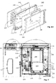
- Fig. 1A and 1B show a schematic view of a first embodiment of the invention.
- a security system 100 here a deposit device
- a five-sided closed, stable and secure housing 101 which surrounds a vault area 102 for receiving at least one (cash) cassette 10 with banknotes 1.
- It has a one- or two-part outer door 103 for closing the housing 101.
- a shutter mechanism 110 eg, an electromechanical lock
- a shutter mechanism 110 is provided for closing and securing the outer door 103 to the housing 101, as in FIG Fig. 4 indicated by an actuator 108 which locks or releases a bolt mechanism 113 of the shutter mechanism 110 via a latch 109 to secure the outer door 103 to the housing 101 or to allow the outer door 103 to be opened.
- the security system 100 includes an in-house protection system 150 (see Fig. 4 ) for protecting the banknotes 1 located in the vault area 102 in the (cash) cassette 10.
- the protection system 150 has a master controller 151 (see FIG Fig. 4 ) Means 152 for neutralizing the banknotes 1 (see Fig. 5 ) and an input unit 140 (see, eg Fig. 4 ) on.
- the shutter mechanism 110 is an electromechanical shutter mechanism 110 that forms an assembly 90 together with the master controller 151.
- the assembly 90 additionally comprises the input unit 140 and it is mounted inside the outer door 103 so that it closes and secures electro-mechanically via a closure member (here a latch 109) on the bolt mechanism 113 of the shutter mechanism 110 to the outer door 103 against the housing 101 to secure or release for opening.
- the input unit 140 is arranged so that it can be operated externally when the outer door 103 is closed, ie at least part of the input unit 140 is accessible from the outside of the outer door 103.
- FIG. 2 shows a schematic perspective view of the safe body 160 of the first security system 100 Fig. 1A and 1B ,
- a safe body 160 preferably serves as the housing 101.
- a safe body 160 in the sense of the invention is a single-walled or multi-walled one executed housing, which is preferably made of steel and here only on one side (here called front) is open.
- the safe body 160 includes walls that serve as right and left side walls 161, 162, bottom 163, back wall 165, and top 164. These walls are assembled into a unit or made as a unit that has no joints or the like to the outside. In the finished state, the safe body 160 acts as if it had been made of one piece or cast.
- an electrical safety net 118 is inserted in the walls to detect the attempt of penetration by means of drilling or other tools.
- Fig. 2 1 a small portion of an example electrical safety net 118 is shown in a highly schematic representation.
- the electrical safety net 118 is connected to the master controller 151 or to a second controller (slave controller 180 in FIG Fig. 4 ) so conductively connected that a manipulation or intrusion attempt detected and neutralizing the banknotes 1 can be triggered.
- the walls are preferably multi-layered, with the electrical safety net 118 lying between two metal layers.
- an outer door 103 is attached, such as in the Figures 1A and 1B can be seen.
- Particularly preferred embodiments are those in which the outer door 103 is mounted and guided on the safe body 160 in such a way that, when opening, it pivots at least partially into the interior of the safe body 160, as in FIG Fig. 3 can be seen.
- a metal strip eg in shape an external door rebate
- a tool eg a crowbar
- Fig. 3 shows a schematic perspective view of a second security system 100, in which the safe body 160 and the outer door 103 are designed so that the outer door 103 during opening at least partially pivots into the interior of the safe body 160.
- a (cash) cassette 10 which is arranged below a feeder module 130, is seated in the safe area 102.
- the electromechanical locking mechanism 110, the master controller 151 and the input unit 140 form an assembly 90, allows this assembly 90 as a whole in a protected area of the outer door 103 to install.
- This assembly 90 moves in solidarity when opening and closing together with the outer door 103rd
- a protected region is a region which, according to the invention, is protected from the outside by the surface 142 of the input unit 140 and from the inside by a stable (preferably closed) structure 104.
- a metal housing serves as a closed enclosure 104
- Fig. 3 is a part of the closed enclosure 104 can be seen on the inside of the outer door 103.
- the structure comprises the element 104 and a lateral protection plate 116 (also called inner covering). It may also include an additional lateral guard plate 115 (also called a bracket angle) that covers, in whole or in part, a portion comprising a (reed) sensor of the upper door 131 and / or an IR checkpoint 107 (see FIG Fig. 8 ).
- the protection system 150 serves as an electrical, intelligent part of the security system 100.
- the protection system 150 comprises in all embodiments the master controller 151, which includes both the input unit 140 and a processor 153, the shutter mechanism 110, at least one communication interface 154 and / or 155 and at least one sensor 156 includes.
- the master controller 151 together with the closure mechanism 110, forms a construction, control and control group, ie a functional unit results which interacts mechanically and electrically.
- the master controller 151 does not only take control of the shutter mechanism 110, but also outputs visual information on a display 144, receives inputs by controls 143 of the input unit 140, receives signals from at least the at least one sensor 156 and the communication with an external user device 200 (eg a PDA or mobile phone) via a communication interface 154 and / or 155.
- the control of the shutter mechanism 110 is done by the master controller 151, respectively the processor 153, signals via a (mechanically and / or electrically) protected connection S1 transmitted to the shutter mechanism 110.
- the master controller 151 can bring the actuator 108 of the locking mechanism 110 back to pull the latch 109 out of a recess 111 of a bolt mechanism 113 and thus make it possible to open the outer door 103.
- the latch 109 is automatically (automatically) reset and locks the bolt mechanism 113, as the case 109 penetrates into the recess 111 of the bolt mechanism 113.
- the reset and locking happens when the outer door 103 has not been opened in the meantime. If the outer door 103, however, was opened, the bolt mechanism 113 including recess 111 has moved slightly and the case 109 can not penetrate into the recess 111 when resetting. Only when the outer door 103 is closed, the bolt mechanism 113 including recess 111 into the starting position and the case 109 penetrates into the recess 111 so as to lock the bolt mechanism 113 and thus also the outer door 103.
- the master controller 151 In addition to the pure control function, the master controller 151 also supplies the shutter mechanism 110 with power. That The closure mechanism 110 is connected to the master controller 151 both in terms of supply technology and communication technology.
- the master controller 151 preferably also controls an IR checkpoint 107 which is seated on the outside door 103 inside the housing 101.
- the IR control point 107 is preferably connected to the master controller 151 via a cable or fiber-based bus system 30, as in FIG Fig. 4 shown schematically.
- the IR checkpoint 107 is configured to establish an IR communication link (IR1) with a (cash) cassette 10 located in the vault area 102. Via this IR communication link IR1, which is preferably bidirectionally interpreted in all embodiments, the master controller 151 can trigger the neutralization of banknotes 1 by triggering the means for neutralizing 152 the (cash) cassette 10.
- IR1 IR communication link
- IR communication link IR1 represented by the block arrow 12, which transmits IR signals to the IR checkpoint 13 of the (cash) cassette 10 and transmits signals from the IR checkpoint 13 back to the IR checkpoint 107 in a bidirectional connection.
- a window or opening 15 (see Fig. 1B ), behind which the IR checkpoint 13 is seated.
- the master controller 151 in all embodiments includes a processor 153 that is controlled with control software that is proprietary.
- the processor 153 forms with the control software a kind of "embedded system", which is secured against manipulation.
- the master controller 151 includes in all embodiments an intrinsic and self-sufficient safety function that detects unauthorized manipulations and triggers reactions depending on the situation. If e.g. If incorrect inputs are made to the operating elements 143, the safety system can be used e.g. be completely disabled for a period of time and / or an increased alarm level may be set, e.g. to prepare the (cash) cassette 10 for triggering the neutralization.
- This intrinsic safety function is preferably supported by a plurality of sensors 156 and / or the safety net 117 and / or 118 attached to the outer door 103 and / or to and / or in the housing 101.
- the (cash) cassette 10 is preferably connected to the Notenprüfer 170 in all embodiments so that bills 1 pass through a feeder module 130 inside the security system 100 and there in the receiving area (interior 2) of the (money) cassette 10 transferred be, similar to this example also with ATM machines is the case.
- the (cash) cassette 10 in all embodiments has its own buffer in the form of a rechargeable battery 14, which is designed and dimensioned such that the (Cash) cassette 10 over several years self-sufficient power can be supplied to trigger the neutralization of the banknotes 1 in an emergency.
- the security system 100 preferably includes a slave controller 180 in all embodiments (see Fig. 4 ), which is connected via the aforementioned bus 30 to the master controller 151.
- the slave controller 180 is seated in the housing 101 and is typically not attached to the exterior door 103.
- the safety system 100 can be supplied externally via a mains voltage connection 20 with mains voltage (for example, 220 V).
- the slave controller 180 if present, preferably includes a power manager and communication control elements in all embodiments.
- the slave controller 180 if present, preferably includes in all embodiments its own buffer in the form of a rechargeable battery 23, which is designed and dimensioned so that the slave controller 180 can independently self-power for several days.
- a very loud siren (not shown) may be disposed in or on the housing 101.
- the slave controller 180 if present, preferably includes in all embodiments a communication interface 181 for connection to an operator console 190 and / or at least one other security system 100.
- a communication interface 181 for connection to an operator console 190 and / or at least one other security system 100.
- Fig. 4 is the communication connection between the slave controller 180 and the control panel 190 is designated K1.
- a cash register system 300 of the invention comprising at least two security systems 100, a bus or communication link K1, and a control console 190.
- the cash register system 300 includes at least one cash register or point-of-sales (POS) terminal.
- POS point-of-sales
- the communication interface 181 preferably provides a Hypertext Transfer Protocol Secure (https) connection that enables browser-based control or retrieval of certain information over a network.
- https connection can be made with the control panel 190 and / or e.g. be set up with another computer.
- the communication interface 181 also preferably provides an Ethernet connection that facilitates connection e.g. with a cash register or a point-of-sales (POS) terminal.
- POS point-of-sales
- the control console 190 if present, preferably includes in all embodiments controls 191 and a display 192.
- the controls 191 may be the same or different from the controls 143.
- the control panel 190 may in all embodiments from the outside via a mains voltage connection 22 with mains voltage (eg 220V).
- the input unit 140 of the security system 100 makes it possible to "recognize” the user by performing an authentication, for example with a portable device 200 (eg a PDA or mobile telephone), for example via the IR communication connection IR2.
- a portable device 200 eg a PDA or mobile telephone
- a "recognition" of the user is performed by the user brings the portable device 200 in the vicinity of the input unit 140, so that an RFID sensor of the input unit 140 an RFID chip of the device 200 can read.
- an input code may be communicated to the user's portable device 200 by another system via message (e.g., via SMS).
- the same input code is also transmitted to the master controller 151. If the user now enters the correct code via the controls 143, the master controller 151 may be e.g. the opening of the outer door 103 release by the master controller 151 controls the actuator 108 to pull the case 109 from the recess 111 of the locking mechanism 113 back.
- the outer door 103 can be unlocked and opened by moving the bolt mechanism 113.
- the bolt mechanism 113 comprises the door traps 135.
- the door traps 135 are moved back, thus freeing the outer door 103.
- the (cash) cassette 10 is switched over the IR communication interfaces 154 and 13 and the IR communication link IR1 (from the saved (armed) mode to a non-armored or transport mode) for the (cash) cassette 10 to be removed can be without neutralizing the banknotes 1.
- the IR communication connection IR2 is preferably encrypted in all embodiments, whereas the IR communication connection IR1 does not necessarily have to be encrypted, since it is only used when the outside door 103 is closed and the system 100 is secure and since it is not receivable or manipulatable from outside.
- the (cash) cassette 10 has a cassette-shaped housing enclosing an interior space 2 (referred to here as a receiving area).
- This receiving area is for receiving schematically illustrated banknotes 1 designed (see Fig. 5 ).
- the receiving area is accessible via an access opening, which is not shown here.
- the receiving area is securable by one or more security means (here called neutralizing means 152).
- the means for neutralizing 152 comprise an igniter 3 with a bolt, which can be triggered by the application of an electrical signal.
- the bolt penetrates a membrane of a print cartridge 6, thus pressurizing an ink module 4.
- the ink module 4 containing a liquid for neutralizing the banknotes 1 communicates with the print cartridge 6 and a distributor plate 5.
- ink module 4 is also understood to mean a module having another liquid (e.g., a DNA liquid) as ink or other flowable medium. Accordingly, the term liquid should also be understood to mean another fluid medium, and the term inking of the banknotes 1 should also be understood to mean another change which can be caused by a flowable medium, for example etching or marking. It is also possible to provide a plurality of ink modules 4; in particular, it may be provided to configure and arrange a plurality of ink modules 4 such that liquid can be dispensed onto the bank notes 1 from several directions.
- a DNA liquid e.g., a DNA liquid
- the ink module 4 has a port for establishing pressure communication with the gas pressure cartridge 6 and an exit region for discharging the fluid.
- the distributor plate 5 has at least one liquid channel and a number of outlet openings for the liquid.
- the distributor plate 5 can be connected to the outlet region of the ink module 4.
- the ink module 4 forms with the distributor plate 5 an assembly, wherein the distributor plate 5 when attaching to the ink module 4 pressure-tight with the outlet region of the ink module 5 is connectable.
- the gas pressure cartridge 6 is connected to the igniter 3, that the igniter 3 is triggered upon application of the electrical signal and with the aforementioned bolt, the membrane of the gas pressure cartridge 6 is severed. This will be gas discharged from the gas pressure cartridge 6 and passed over the pressure connection in the ink module 4. Under this pressure, the liquid passes from the ink module into the liquid channel of the distributor plate 5 and through the outlet openings of the distributor plate 5 in the direction of the banknotes 1 Fig. 5 is shown by arrows 7, the coloring of the banknotes 1.
- Fig. 5 shows a circuit 11 with an IR safety interface 12, via which the circuit 11 can be controlled by an external control element, such as the master controller 151, as shown schematically.
- the external control element essentially serves to bring the protection system of the (cash) cassette 10 from a non-armed or passive state into an armed or active state. Only when the protection system is armed or activated, the detonator 3 is triggered in an unauthorized handling of the security system 100 and the neutralization or coloring of the banknotes 1 initiated.
- the circuit 11 for this purpose comprises a processor (not shown), which makes the (cash) cassette 10 self-sufficient, so that it can trigger a reaction.
- the triggering of responses may also be caused by the master controller 151. This is done via the IR communication link IR1.
- the master controller 151 may preferably initiate a reaction of the (cash) cassette 10 in all embodiments via the IR communication link IR1, even if the (cash) cassette 10 or its own protection system of the (cash) cassette 10 (still ) has detected no threat.
- the communication interface 155 can be designed as an RFID interface.
- the RF / ID interface may in all embodiments comprise an RFID chip located below the surface 142 of the input unit 140 so as not to be manipulated.
- the user may hold a portable device 200 to the input unit 140 for the RFID chip to read data from the portable device 200 and for the master controller 151 to examine that data.
- the use of the RFID interface can be part of the complete Authentication of the user, as already described by way of example.
- a partial step of the complete authentication of the user must be carried out via the input unit 140.
- it may be required to enter a PIN code via the input unit 140 prior to depositing, or to be required to authenticate the depositor by an RFID code of its portable device 200.
- the security system 100 in all embodiments comprises means for recording (called recording module 80) of all events in order to be able to evaluate the records after an incident.
- the records can be transmitted to a memory of the (cash) cassette 10, for example.
- the records can also be transmitted to a memory of a purse in the (cash) cassette 10, for example.
- a storage medium is shown as a recording module 80, which is connected to the master controller 151 via the bus 30.
- FIGS. 6A, 6B, 6C and 6D Details of a preferred embodiment of such input unit 140 are shown.
- surface 142 of input unit 140 is shown.
- controls 143 eg in the form of a keypad
- a display 144 is provided in the surface 142.
- the input unit 140 is designed for the manual entry of a (PIN and / or via SMS transmitted access) codes. To enter the code, the aforementioned controls 143 can be used.
- the input unit 140 has an interface 141 (preferably in the form of the mentioned IR communication connection IR2), which is designed for contactless communication with a portable user device 200. It can For example, the IR interface 154 of the protection system 150 serve as an interface 141.
- Fig. 1A an embodiment is shown in which the interface 141 sits below the surface 142 of the input unit 140.
- FIGS. 6A, 6B and 6D an embodiment is shown in which the interface 141 is seated in the surface 142 of the input unit 140, that is integrated directly into the multiply mentioned assembly 90.
- the interface 141 is designed as an optically transparent window, behind which sits an optical transmitter / receiver of the communications interface 154. If it is an RF interface 141 (e.g., communication interface 155), then no optically transparent window needs to be specified. In this case, a portion of the surface 142 or outer door 103 which is "transparent" to electromagnetic waves, i. in this case, the interface 141 is designed as an RF port (e.g., in the form of an integrated antenna).
- FIG. 15 shows a view of the surface 142 of the input unit 140 Fig. 6A after assembly and Fig. 6C shows a sectional view of the input unit 140 along the line AA in Fig. 6B , In Figs. 6B and 6C It can be seen that the surface 142 is preferably inserted into a circumferential, stable frame 145.
- Fig. 6D shows an exploded view of the essential elements of the input unit 140 after Fig. 6B ,
- the input unit 140 comprises the surface 142, the stable frame 145, a circuit board 146, which here carries a second board 148 on spacers, and a mounting frame 149.
- the connecting elements 147 which are designed here in the form of pins, here have a purely mechanical function and have threads, so that the input unit 140 can be connected to the outer door 103.
- the second board 148 preferably serves to provide an electrical connection with other elements.
- a foil or (glass) plate may serve as the surface 142 of the input unit 140.
- Either the controls 143 are integrated into the foil or (glass) plate, or they sit below the foil or (glass) plate.
- the surface 142 is configured as a touch screen, touch screen, touch screen, or touch screen.
- the surface 142 may be designed to be impact resistant in all embodiments.
- the input unit 140 comprises an outer plastic layer (e.g., a polyester layer) as the surface 142 and an inner circuit board 146 with circuitry (preferably in IC form) that implements all functions important to controlling the input and output functions.
- the printed circuit board preferably carries, among other things, the processor 153 and other elements of the master controller 151.
- the input unit 140 serves as a combined input and output device (for input of commands or codes and for displaying information on the display 144) in which functions of the security system 100 can be directly controlled by touching portions of the surface 142. wherein the actual control sovereignty lies with the processor 153 designed as an "embedded system".
- the input unit 140 includes electrical connection (s) in the form of protected (flexible flat) cables or wiring harnesses, not shown in the figures.
- Fig. 7 shows an interior view of an embodiment of an outer door 103.
- the front of the security system 100 is, as in the FIGS. 1A, 1B to recognize, preferably designed in two parts.
- a front plate 131 may be provided with an opening 132, behind which the feeder module 130 of the Notenprüfers 170 sits.
- the front of the security system 100 can also, as in Fig. 3 can be seen to be made in one piece.
- a two-part door is preferred, however, because the pull-in module 130 can be accessed via the upper door 131 without allowing removal or manipulation of the (cash) cassette 10, since it sits behind the outer door 103.
- a mechanical (cylinder) lock 133 may be provided to unlock the front panel 131 by inserting and turning a key.
- this lock 133 can be seen from behind.
- the mechanical lock 133 may be configured to actuate a latch 136 that engages the front panel 131.
- a mechanical bolt 134 can be provided on the inside of the outer door 103 in order to be able to unlock the outer door 103 by manual actuation. In Fig. 7 and Fig. 8 this bar 134 can be seen from behind.
- Such a mechanical latch 134 is preferably provided in all embodiments. Through manual actuation, the mechanical latch 134 acts via the bolt mechanism 113 on one or more door traps 135, which lock the outer door 103 with respect to the safe body 160 (ie, with respect to the housing 101).
- the mechanical latch 134 may be provided on the outside of the outer door 103 with a ball handle member 106.
- the master controller 151 After successfully identifying a user via the shutter mechanism 110, retracts the latch 109, the latch 113 is released (unlocked) and the user can actuate the latch Ball handle member 106 move the mechanical latch 134 to pull the bolt mechanism 113 including door traps 135 back. Then the outer door 103 can be opened.
- Fig. 8 1 shows an exploded view of the essential elements of an assembly 90 according to the invention.
- the assembly 90 according to the invention comprises at least the master controller 151 with attached or attached closure mechanism 110 and with an input unit 140 installed or attached thereto.
- the outer door 103 in all embodiments inside is occupied by an electrical safety network 117, which is connected directly or indirectly (eg via an intermediate circuit) to the master controller 151.
- Fig. 7 schematically a small portion of the safety net 117 is shown. By this measure, the violent penetration (eg with a drill) can be detected early.
- the safety net 117 serves as the sensor 156 in FIG Fig. 4 ,
- jacks 137 may be arranged coaxially with each other to receive a pivot axis 138.
- the outer door 103 and / or the front plate 131 are pivoted when opening about the pivot axis 138.
- the position of the pivot axis 138 is indicated by its axis of rotation DA.
- a voltage connection printed circuit 112 may be provided on the inside of the outer door 103 to enable the power supply of the assembly 90 (eg, as a connection to the AC / DC converter 21).
- the power supply of the assembly 90 can in all embodiments but also on in Fig. 4 Bus 30 shown done.
- the assembly 90 is designed so that a reaction is triggered in the event of a power interruption.
- interruption of the power supply in response may trigger the neutralization of the banknotes 1, which are in the (cash) cassette 10 in the vault area 102. This response is triggered by the master controller 151 via the internal IR communication link IR1 to the (cash) cassette 10 and the neutralization means 152 located therein.
- an electro-mechanical shutter mechanism 110 acts on a closure element 109 (also called trap or nose), which indirectly secures the outer door 103 with respect to the safe body 160 and the housing 101.
- a closure element 109 also called trap or nose
- FIG. 8 An embodiment is shown in which the locking mechanism 110 moves the closure element 109 in the form of a trap or nose.
- the trap or nose engages in a recess 111 (not in Fig. 8 to recognize) a locking mechanism 113, which is movably guided connected to the door traps 135.
- the trap or nose of the closure element 109 sits in the cutout 111 of the bolt mechanism 113 (see Fig. 7 ) and the bolt mechanism 113 can not be moved.
- the bolt mechanism 113 can move. If the bolt mechanism 113 can be moved, the door traps 135 can be moved back with the bolt mechanism 113 so as to unlock the outer door 103. The moving back of the door traps 135 happens here by manually moving the ball grip member 106 of the bolt 134th
- the outer door 103 preferably comprises at least one door sensor (preferably in the form of a reed sensor 114) in order to be able to determine the position (open or closed) of the outer door 103 and to additionally secure the assembly 90 against tampering.
- the reed sensor 114 may be connected as a sensor 156 to the master controller 151.
- the assembly 90 is configured such that the input unit 140 is fixed mechanically to the closure mechanism 110 connected (eg by screws) is.
- the input unit 140 and the shutter mechanism 110 may also be housed in a common housing (enclosure 104) so as to form the assembly 90.
- the security system 100 is configured such that the critical mechanical elements, such as the lock 133 and the latch 134, and / or the protection system 150 are covered at the rear by a protective plate 116.
- the protection plate 116 includes a small window 121 to allow IR communication IR1 with the (cash) cassette 10.
- the security system 100 is designed such that the walls of the housing 101 and at least the outer door 103 are covered with a safety net 118 and / or 117, as in FIG Fig. 2 and Fig. 7 indicated.
- the safety net (s) 117 and / or 118 are connected directly or indirectly (eg via an intermediate circuit) to the master controller 151.
- the violent penetration eg with a drill
- the violent penetration can be detected early.
Abstract
Description
Die Erfindung betrifft ein Sicherheitssystem, das zur Aufnahme von Banknoten ausgelegt ist und ein entsprechendes Kassensystem.The invention relates to a security system that is designed to receive banknotes and a corresponding POS system.
Es gibt verschiedenste Sicherheitssysteme zur Aufnahme und zum Lagern von solchen Banknoten und Sicherheitskoffer oder -kassetten zum Transport von schutzbedürftigen Banknoten.There are a variety of security systems for receiving and storing such banknotes and security cases or cassettes for transporting vulnerable banknotes.
Die entsprechenden Systeme weisen einen Innenbereich, ein Schutzsystem und eine Zugriffsöffnung auf, um das System öffnen und den Innenbereich zugänglich machen zu können.The corresponding systems have an interior area, a protection system and an access opening in order to open the system and make it accessible to the interior.
Das Schutzsystem dient dazu, die Banknoten, wenn diese bei einem Diebstahl abhanden kommen sollten, dagegen zu schützen, dass sie in den Handel gelangen oder bei Banken eingetauscht werden können. Dies geschieht, indem die Banknoten in einem solchen Fall automatisch neutralisiert bzw. eingefärbt werden. Die entsprechenden Schutzsysteme sind teuer und aufwendig.The purpose of the protection system is to protect the banknotes if they are lost in the event of a theft against being placed on the market or being exchangeable at banks. This is done by automatically neutralizing or coloring the banknotes in such a case. The corresponding protection systems are expensive and expensive.
Es gibt, wie schon erwähnt, verschiedene Volumen von Banknoten zu transportieren. Je nach Anzahl der Banknoten müssen die System unterschiedliche Größen und Sicherheitsmerkmale haben. Ausserdem können unterschiedlichste Sicherheitsvorschriften gelten. Dienstleister, die im Bereich der Werttransporte tätig sind, haben häufig mindestens drei verschiedene Lösungen zur Auswahl und zwar eine zum Beschicken von Geldautomaten mit Geld, eine zum Abholen von Geld bei Handelsgeschäften und eine zum Anliefern von Geld an Banken. Jede diese Lösungen hat seine eigenen Spezifikationen. In der Praxis sind daher eine grosse Zahl von verschiedensten Systeme im Einsatz, die oft nicht kompatibel sind.There are, as already mentioned, different volumes of banknotes to transport. Depending on the number of banknotes, the systems must have different sizes and security features. In addition, various safety regulations can apply. Service providers involved in the transportation of valuables often have at least three different solutions to choose from, including one to load cash machines with money, one to pick up money in trading transactions, and one to deliver money to banks. Each of these solutions has its own specifications. In practice, therefore, a large number of different systems are in use, which are often incompatible.
Die heutigen Systeme sind relativ teuer und klobig. Ausserdem ist bisher der sicherheitstechnische Aufwand groß, der erforderlich ist, um mit den beschriebenen Mitteln eine sichere Aufbewahrung und einen sicheren Transport von einem Ort zu einem anderen Ort gewährleisten zu können.Today's systems are relatively expensive and clunky. In addition, so far, the safety effort is large, which is necessary to ensure the means described safe storage and safe transport from one place to another place.
Besonders groß ist der Bedarf für ein Sicherheitssystem, das es ermöglicht Geldscheine aufzunehmen und sicher zu verwahren, bis diese abgeholt und z.B. zu einer Bank gebracht werden. Gerade in Handelsgeschäften könnte durch den Einsatz eines durchdachten Sicherheitssystems das Risiko vermindert werden, das mit der Handhabung grosser Mengen von Geldscheinen verbunden ist. Ausserdem kann das Entwenden von Geldscheinen im Handelsgeschäft verunmöglicht werden.Particularly large is the need for a security system that allows you to take notes and safekeep until they are picked up and, for example. be brought to a bank. Especially in commercial transactions, the use of a sophisticated security system could reduce the risk associated with handling large amounts of bills. In addition, the stealing of banknotes in the trading business can be made impossible.
Daraus ergibt sich seit längerem der Bedarf für eine Vereinheitlichung der Systeme und für deren Vereinfachung, wobei es das Ziel ist ein Maximum an Sicherheit bei einem Minimum and Aufwand und Kosten bieten zu können.This has long led to the need for standardization and simplification of systems, with the aim of providing maximum security at a minimum of effort and cost.
Es ist daher Aufgabe der Erfindung,
- eine Sicherheitslösung der eingangs genannten Art zu schaffen, die eine hohe Sicherheit gewährleistet und einfach zu handhaben ist,
- eine Sicherheitslösung der eingangs genannten Art zu schaffen, die möglichst universell einsetzbar und autark ist,
- eine Sicherheitslösung der eingangs genannten Art zu schaffen, die eine hohe Flexibilität in der Handhabbarkeit ermöglicht, und
- eine Sicherheitslösung der eingangs genannten Art zu schaffen, die kostengünstig ist.
- to provide a security solution of the type mentioned above, which ensures a high level of security and is easy to handle,
- to provide a security solution of the type mentioned, which is as universally applicable and self-sufficient,
- to provide a security solution of the type mentioned, which allows a high flexibility in the handling, and
- to provide a security solution of the type mentioned, which is inexpensive.
Zusätzlich wäre es erstrebenswert, wenn die Sicherheitslösung eine lückenlose Überwachung der Geldströme ermöglichen würde.In addition, it would be desirable if the security solution would allow complete monitoring of the cash flows.
Die Lösung dieser Aufgabe erfolgt für Sicherheitssystem, vorzugsweise in Form eines Tresors, durch die kennzeichnenden Merkmale des Anspruchs 1.The solution to this problem is for security system, preferably in the form of a vault, by the characterizing features of
Bevorzugte Weiterbildungen des Sicherheitssystems sind durch die abhängigen Ansprüche definiert.Preferred developments of the safety system are defined by the dependent claims.
Das Sicherheitssystem baut auf dem folgenden Prinzip auf. Es wird ein Gehäuse bereit gestellt, das einen Tresorbereich zur Aufnahme von Banknoten umgibt. Eine Aussentüre dient zum Verschliessen des Gehäuses und ein Verschlussmechanismus ist zum Schliessen und Sichern der Aussentüre gegenüber dem Gehäuse vorgesehen. Das Sicherheitssystem umfasst ein Schutzsystem zum Schützen der im Tresorbereich befindlichen Banknoten, wobei das Schutzsystem Mittel zum Neutralisieren der Banknoten umfasst. Das Sicherheitssystem umfasst ein Hauptkontroll- und Steuersystem (Master-Controller genannt) und einen elektro-mechanischen Verschlussmechanismus. Der Verschlussmechanismus bildet zusammen mit dem Master-Controller eine Bau-, Steuer- und Kontrollgruppe (Baugruppe genannt), die innenliegend an der Aussentüre so angebracht ist, dass sie zum Schliessen und Sichern elektro-mechanisch auf mindestens ein Verschlusselement einwirken kann, um die Aussentüre gegenüber dem Gehäuse zu sichern. Die Baugruppe umfasst zusätzlich eine Eingabeeinheit, die bei geschlossener Aussentüre von Aussen bedienbar ist.The security system is based on the following principle. A housing is provided which surrounds a safe area for receiving banknotes. An outer door serves to close the housing and a locking mechanism is provided for closing and securing the outer door with respect to the housing. The security system comprises a protection system for protecting banknotes in the vault area, the protection system comprising means for neutralizing the banknotes. The safety system includes a main control and control system (called master controller) and an electro-mechanical locking mechanism. The locking mechanism forms together with the master controller a construction, control and control group (assembly called), which is mounted inside the outer door so that they can act electromechanically closing and securing at least one closure element to the outside door Secure against the housing. The module also includes an input unit that can be operated externally when the outside door is closed.
Gemäss Erfindung handelt es sich bei dem Verschlussmechanismus um einen elektro-mechanischen Verschlussmechanismus, der zusammen mit dem Master-Controller eine Baugruppe bildet. Die Baugruppe umfasst zusätzlich die Eingabeeinheit. Die Baugruppe ist so an der Aussentüre angebracht, dass sie zum Schliessen und Sichern elektro-mechanisch auf das Verschlusselement einwirken kann, um die Aussentüre gegenüber dem Gehäuse zu sichern.According to the invention, the locking mechanism is an electro-mechanical locking mechanism which, together with the Master controller forms an assembly. The module additionally includes the input unit. The assembly is mounted on the outer door so that it can act electromechanically on the closure element for closing and securing, in order to secure the outer door with respect to the housing.
Die Eingabeeinheit ist vorzugsweise zur manuellen Eingabe eines Codes ausgelegt und umfasst eine Schnittstelle zur berührungslosen Kommunikation (vorzugsweise in Form einer IR-Kommunikation) mit einem tragbaren Benutzergerät. Diese Schnittstelle ist vorzugsweise verdeckt hinter einer Oberfläche der Eingabeeinheit angeordnet und durch diese geschützt.The input unit is preferably designed for manually entering a code and comprises an interface for contactless communication (preferably in the form of an IR communication) with a portable user device. This interface is preferably arranged hidden behind a surface of the input unit and protected by this.
Das Sicherheitssystem umfasst vorzugsweise ein Aufzeichnungsmodul zum Aufzeichnen von Transaktionen, wie z.B. Bedienaktionen.The security system preferably comprises a recording module for recording transactions, e.g. Operator actions.
Der Master-Controller ist vorzugsweise als geschlossenes, proprietäres (embedded) System ausgelegt und eine Steuersoftware ist in einem Speicher gespeichert, um Aktionen und Reaktion der Baugruppe auszuführen. Die Steuersoftware wirkt mit einem Prozessor des Master-Controllers zusammen, um eine intrinsische und autarke Sicherheitsfunktion des Sicherheitssystems zu realisieren.The master controller is preferably designed as a closed, proprietary (embedded) system, and control software is stored in memory to perform actions and reaction of the assembly. The control software interacts with a processor of the master controller to realize an intrinsic and self-sufficient security function of the security system.
Der elektro-mechanische Verschlussmechanismus sitzt vorzugsweise hinter einer Bedienoberfläche der Eingabeeinheit und schützt den elektro-mechanische Verschlussmechanismus gegen Manipulation von Aussen.The electro-mechanical locking mechanism is preferably located behind a user interface of the input unit and protects the electro-mechanical locking mechanism against manipulation from the outside.
Der Tresorbereich ist vorzugsweise zur Aufnahme von Banknoten ausgelegt, die sich in einer (Geld)Kassette befinden, die eine eigene Schutzschaltung umfasst, die nach dem Einbringen in den Tresorbereich intern über eine Kommunikationsverbindung mit dem Master-Controller in Verbindung steht, und die Mittel zum Neutralisieren der Banknoten in der Kassette o umfasst.The vault area is preferably designed to receive banknotes that are located in a (cash) cassette that includes its own protection circuit that is internally connected to the master controller via a communication link after insertion into the vault area, and the means for Neutralizing the banknotes in the cassette o includes.
Vorzugsweise kann der Master-Controller über eine interne kabellose Kommunikationsverbindung auf die Schutzschaltung einer (Geld)Kassette einwirken, um die Mittel zum Neutralisieren der Banknoten auszulösen.Preferably, the master controller can act on the protection circuit of a (cash) cassette via an internal wireless communication link to trigger the means for neutralizing the banknotes.
Vorzugsweise handelt es sich bei dem Sicherheitssystem um ein Einzahl- oder Aufnahmegerät für Geldscheine, das einen Einzugmodul zum Einziehen der Geldscheine umfasst, wobei die Geldscheine in das Innere des Innenbereichs überführt werden, und wobei das Einzugmodul vorzugsweise mit einer (Geld)Kassette im Tresorbereich so verbunden ist, dass die Geldscheine automatisch von dem Einzugmodul in die Geldkassette gefördert werden können.Preferably, the security system is a banknote deposit or pick-up device comprising a feeder module for withdrawing the bills, the bills being transferred to the interior of the interior, and the feeder module preferably having a (cash) cassette in the vault area connected, that the bills can be automatically funded by the feeder module in the cashbox.
Das Sicherheitssystem verfügt vorzugsweise über eine Kommunikationsverbindung, die dazu ausgelegt ist Transaktionsdaten an einen räumlich entfernten Rechner und/oder eine Konsole übertragen zu können, wobei die Übertragung dieser Transaktionsdaten erfolgt, um ein Cash-Management zu ermöglichen.The security system preferably has a communication link that is adapted to be able to transmit transaction data to a remote computer and / or a console, wherein the transmission of this transaction data is carried out to enable cash management.
Das Sicherheitssystem verfügt vorzugsweise über einen oder mehrere Sensoren, die schaltungstechnisch so mit dem Master-Controller verbunden sind, dass sie durch den Master-Controller überwachbar oder abfragbar sind, um die Sicherheit des Sicherheitssystems als Ganzes zu verbessern.The security system preferably has one or more sensors that are circuitry connected to the master controller such that they are monitorable or interrogatable by the master controller to enhance the security of the security system as a whole.
Das Sicherheitssystem der Erfindung wird auch als "smart system" bezeichnet, um der Flexibilität der entsprechenden Lösung Rechnung zu tragen.The security system of the invention is also referred to as a "smart system" to account for the flexibility of the corresponding solution.
Durch das Sicherheitssystem der Erfindung wird vor allem das Risiko interner Diebstähle und Missbrauchsfälle reduziert, da ein lückenloses und sicheres Handhaben der Banknoten ermöglicht wird.The security system of the invention, above all, reduces the risk of internal theft and cases of abuse, since a complete and secure handling of the banknotes is made possible.
Weitere Merkmale und Einzelheiten der Erfindung werden im Folgenden an Hand von Ausführungsbeispielen und mit Bezug auf die Zeichnung ausführlich erläutert.
- Fig. 1A
- zeigt ein erstes Sicherheitssystem in Form eines Einzahlgeräts in einer schematischen Perspektivansicht mit geschlossener und gesicherter Aussentüre;
- Fig. 1B
- zeigt das erste Sicherheitssystem nach
Fig. 1A mit geöffneter Aussentüre; - Fig. 2
- zeigt eine schematische Perspektivansicht des Gehäuses des ersten Sicherheitssystems nach
Fig. 1A , das hier als Tresorkorpus bezeichnet wird; - Fig. 3
- zeigt eine schematische Perspektivansicht des Tresorkorpus eines zweiten Sicherheitssystems mit geöffneter Aussentüre;
- Fig. 4
- zeigt eine schematische Blockdarstellung des elektrischen Teils des Sicherheitssystems (innenliegendes Schutzsystem genannt) der Erfindung;
- Fig. 5
- zeigt eine schematischen Draufsicht auf eine geöffnete, beispielhaft gezeigte Geldkassette;
- Fig. 6A
- zeigt ein Ansicht der Oberfläche einer möglichen Eingabeeinheit;
- Fig. 6B
- zeigt ein Ansicht der Oberfläche der Eingabeeinheit nach
Fig. 6A nach der Montage; - Fig. 6C
- zeigt ein Schnittansicht der Eingabeeinheit nach
Fig. 6B ; - Fig. 6D
- zeigt ein Explosionszeichnung der wesentlichen Elemente der Eingabeeinheit nach
Fig. 6B ; - Fig. 7
- zeigt eine Innenansicht einer Ausführungsform einer zweiteiligen Aussentüre;
- Fig. 8
- zeigt eine Explosionszeichnung der wesentlichen Elemente einer Aussentüre samt erfindungsgemässer Baugruppe;
- Fig. 9
- zeigt eine schematische Ansicht eines tragbaren Geräts, das im Zusammenhang mit der Erfindung zum Einsatz kommen kann,
- Fig. 10
- zeigt eine schematische Ansicht eines Kassensystems der Erfindung.
- Fig. 1A
- shows a first security system in the form of a Einzahlgeräts in a schematic perspective view with closed and secured outer door;
- Fig. 1B
- shows the first security system
Fig. 1A with opened outside door; - Fig. 2
- shows a schematic perspective view of the housing of the first security system after
Fig. 1A , which is referred to here as Vault Corpus; - Fig. 3
- shows a schematic perspective view of the safe corpus of a second security system with open outside door;
- Fig. 4
- shows a schematic block diagram of the electrical part of the safety system (called internal protection system) of the invention;
- Fig. 5
- shows a schematic plan view of an opened cashbox example shown;
- Fig. 6A
- shows a view of the surface of a possible input unit;
- Fig. 6B
- shows a view of the surface of the input unit
Fig. 6A after assembly; - Fig. 6C
- shows a sectional view of the input unit after
Fig. 6B ; - Fig. 6D
- shows an exploded view of the essential elements of the input unit
Fig. 6B ; - Fig. 7
- shows an interior view of an embodiment of a two-part outer door;
- Fig. 8
- shows an exploded view of the essential elements of an outer door including assembly according to the invention;
- Fig. 9
- shows a schematic view of a portable device that can be used in connection with the invention,
- Fig. 10
- shows a schematic view of a POS system of the invention.
Grundsätzlich gleiche bzw. gleich wirkende konstruktive Elemente sind in den Figuren mit gleichen Bezugszeichen versehen, auch wenn sie sich teilweise voneinander unterscheiden.Basically identical or identically acting structural elements are provided in the figures with the same reference numerals, even if they differ from each other in part.
Vorzugsweise ist bei allen Ausführungsformen in die Wandungen ein elektrisches Sicherheitsnetz 118 eingefügt, um den Versuch des Eindringens mittels Bohr- oder anderen Werkzeugen detektieren zu können. In
Vorzugsweise sind die Wandungen bei allen Ausführungsformen mehrschichtig aufgebaut, wobei das elektrische Sicherheitsnetz 118 zwischen zwei Metallschichten liegt.In all embodiments, the walls are preferably multi-layered, with the
An dem Tresorkorpus 160 ist eine Aussentüre 103 angebracht, wie z.B. in den
Besonders bevorzugt sind Ausführungsformen, bei denen der Bereich der Drehachse DA der Aussentüre 103 durch einen Metallstreifen (z.B. in Form einer aussenliegenden Türfalz) gegen Manipulation mit einem Werkzeug (z.B. einem Brecheisen) geschützt ist.Particularly preferred are embodiments in which the region of the axis of rotation DA of the
Die Tatsache, dass gemäss Erfindung der elektro-mechanische Verschlussmechanismus 110, der Master-Controller 151 und die Eingabeeinheit 140 eine Baugruppe 90 bilden, ermöglicht es diese Baugruppe 90 als Ganzes in einen geschützten Bereich der Aussentüre 103 einzubauen. Diese Baugruppe 90 bewegt sich solidarisch beim Öffnen und Schliessen zusammen mit der Aussentüre 103.The fact that according to the invention, the
Als geschützter Bereich wird ein Bereich bezeichnet, der gemäss Erfindung nach Aussen hin durch die Oberfläche 142 der Eingabeeinheit 140 und nach Innen hin durch eine stabile, (vorzugsweise geschlossene) Umbauung 104 geschützt ist.A protected region is a region which, according to the invention, is protected from the outside by the
Vorzugsweise dient bei allen Ausführungsformen ein Metallgehäuse als geschlossene Umbauung 104. In
Anhand von
Das Sicherheitssystems 100 umfasst vorzugsweise bei allen Ausführungsformen einen oder mehrere der folgenden Sensoren 156, die schaltungstechnisch so direkt oder indirekt (z.B. über einen Slave-Controller 180) mit dem Master-Controller 151 verbunden sind, dass sie durch die Master-Controller 151 überwachbar oder abfragbar sind:
- Schlagsensor,
- Bewegungssensor,
- Drucksensor,
- Feuchtigkeitssensor,
- Temperatursensor,
- Zeitgeber oder Zähler,
Sicherheitsnetz 117 und/oder 118.
- Rain sensor,
- Motion sensor,
- Pressure sensor,
- Humidity sensor,
- Temperature sensor,
- Timer or counter,
-
Safety net 117 and / or 118.
Der Master-Controller 151 bildet zusammen mit dem Verschlussmechanismus 110 eine Bau-, Steuer- und Kontrollgruppe, d.h. es ergibt sich eine Funktionseinheit, die mechanisch und elektrisch zusammenwirkt. Der Master-Controller 151 übernimmt dabei nicht nur die Kontrolle (Steuerung) des Verschlussmechanismus 110, sondern auch die Ausgabe von visuellen Informationen auf einer Anzeige 144, das Entgegennehmen von Eingaben durch Bedienelemente 143 der Eingabeeinheit 140, das Entgegennehmen von Signalen mindestens des mindestens einen Sensors 156 und die Kommunikation mit einem externen Benutzergerät 200 (z.B. ein PDA oder Mobiltelefon) über eine Kommunikationsschnittstelle 154 und/oder 155. Die Kontrolle (Steuerung) des Verschlussmechanismus 110 geschieht, indem der Master-Controller 151, respektive der Prozessor 153, Signale über eine (mechanisch und/oder elektrisch) geschützte Verbindung S1 an den Verschlussmechanismus 110 übermittelt. Über die geschützte Verbindung S1 kann der Master-Controller 151 den Aktuator 108 des Verschlussmechanismus 110 dazu bringen die Falle 109 aus einer Ausnehmung 111 eines Riegelwerks 113 zurück zu ziehen und so das Öffnen der Aussentüre 103 zu ermöglichen. Nach einer kurzen Zeit wird die Falle 109 automatisch (selbsttätig) zurückgestellt und verriegelt das Riegelwerk 113, da die Falle 109 in die Ausnehmung 111 des Riegelwerks 113 eindringt. Das Zurückstellen und Verriegeln geschieht dann, wenn die Aussentüre 103 in der Zwischenzeit nicht geöffnet wurde. Falls die Aussentüre 103 hingegen geöffnet wurde, hat sich das Riegelwerk 113 samt Ausnehmung 111 etwas verschoben und die Falle 109 kann beim Rückstellen nicht in die Ausnehmung 111 eindringen. Erst wenn die Aussentüre 103 geschlossen wird, gerät das Riegelwerk 113 samt Ausnehmung 111 in die Ausgangsstellung und die Falle 109 dringt in die Ausnehmung 111, um so das Riegelwerk 113 und damit auch die Aussentüre 103 zu verriegeln.The
Neben der reinen Steuerungsfunktion versorgt der Master-Controller 151 den Verschlussmechanismus 110 auch mit Strom. D.h. der Verschlussmechanismus 110 ist sowohl versorgungstechnisch als auch kommunikationstechnisch mit dem Master-Controller 151 verbunden.In addition to the pure control function, the
Vorzugsweise kontrolliert der Master-Controller 151 bei allen Ausführungsformen auch einen IR-Kontrollpunkt 107, der im Inneren des Gehäuses 101 an der Aussentüre 103 sitzt. Der IR-Kontrollpunkt 107 ist vorzugsweise über ein kabel- oder fiberbasiertes Bussystem 30 mit dem Master-Controller 151 verbunden, wie in
Der Master-Controller 151 umfasst bei allen Ausführungsformen einen Prozessor 153, der mit Steuerungssoftware gesteuert wird, die proprietär ist. Der Prozessor 153 bildet mit der Steuerungssoftware eine Art "embedded system", das gegen Manipulation gesichert ist.The
Der Master-Controller 151 umfasst bei allen Ausführungsformen eine intrinsische und autark funktionierende Sicherheitsfunktion, die unerlaubte Manipulationen erkennt und je nach Situation Reaktionen auslöst. Wenn z.B. falsche Eingaben an den Bedienelementen 143 erfolgen, kann das Sicherheitssystem z.B. für eine gewisse Zeit komplett gesperrt werden und/oder es kann eine erhöhte Alarmstufe vorgegeben werden, um so z.B. die (Geld-)Kassette 10 auf ein Auslösen der Neutralisierung vorzubereiten.The
Diese intrinsische Sicherheitsfunktion wird vorzugsweise durch mehrere Sensoren 156 und/oder das Sicherheitsnetz 117 und/oder 118 unterstützt, die an der Aussentüre 103 und/oder an und/oder im Gehäuse 101 angebracht sind.This intrinsic safety function is preferably supported by a plurality of
Die (Geld-)Kassette 10 ist vorzugsweise bei allen Ausführungsformen mit dem Notenprüfer 170 so verbunden, dass Geldscheine 1 durch ein Einzugmodul 130 hindurch ins Innere des Sicherheitssystems 100 gelangen und dort in den Aufnahmebereich (Innenraum 2) der (Geld-)Kassette 10 überführt werden, ähnlich wie dies z.B. auch bei ATM-Maschinen der Fall ist.The (cash)
Die (Geld-)Kassette 10 hat bei allen Ausführungsformen einen eigenen Buffer in Form eines Akkus 14, der so ausgelegt und dimensioniert ist, dass die (Geld-)Kassette 10 über mehrere Jahre sich selbst autark mit Strom versorgen kann, um im Notfall die Neutralisierung der Banknoten 1 auszulösen.The (cash)
Das Sicherheitssystem 100 umfasst vorzugsweise bei allen Ausführungsformen einen Slave-Controller 180 (siehe
Das Sicherheitssystem 100 kann bei allen Ausführungsformen von aussen über einen Netzspannungsanschluss 20 mit Netzspannung (z.B. 220V) versorgt werden. Ein Wechselspannungs/Gleichspannungs-Wandler 21 kann die für die Systeme/Komponenten des Schutzsystems 150 erforderliche Gleichspannung (V=) erzeugen. Die Gleichspannung (V=) kann über den Bus 30 oder über separate Spannungsleitungen (in
Der Slave-Controller 180, falls vorhanden, umfasst vorzugsweise bei allen Ausführungsformen einen Power Manager und Elemente zur Kommunikations-Kontrolle.The
Der Slave-Controller 180, falls vorhanden, umfasst vorzugsweise bei allen Ausführungsformen einen eigenen Buffer in Form eines Akkus 23, der so ausgelegt und dimensioniert ist, dass sich der Slave-Controller 180 über mehrere Tage selbst autark mit Strom versorgen kann.The
Bei allen Ausführungsformen kann eine sehr laute Sirene (nicht gezeigt) im oder am Gehäuse 101 angeordnet sein.In all embodiments, a very loud siren (not shown) may be disposed in or on the
Der Slave-Controller 180, falls vorhanden, umfasst vorzugsweise bei allen Ausführungsformen eine Kommunikationsschnittstelle 181, um mit einer Bedienkonsole 190 und/oder mindestens einem weiteren Sicherheitssystem 100 verbunden zu werden. In
In
Die Kommunikationsschnittstelle 181 bietet vorzugsweise eine https (Hypertext Transfer Protocol Secure) Verbindung, die ein browser-basiertes Kontrollieren oder Abfragen gewisser Informationen über ein Netzwerk ermöglicht. Die https Verbindung kann mit der Bedienkonsole 190 und/oder z.B. mit einem anderen Computer aufgebaut werden.The
Die Kommunikationsschnittstelle 181 bietet vorzugsweise auch eine Ethernet-Verbindung, die ein Verbinden z.B. mit einer Kasse oder einem Point-Of-Sales (POS) Terminal ermöglicht.The
Die Bedienkonsole 190, falls vorhanden, umfasst vorzugsweise bei allen Ausführungsformen Bedienelemente 191 und eine Anzeige 192. Die Bedienelemente 191 können gleich oder anders ausgeführt sein wie die Bedienelemente 143. Die Bedienkonsole 190 kann bei allen Ausführungsformen von aussen über einen Netzspannungsanschluss 22 mit Netzspannung (z.B. 220V) versorgt werden. Ein Wechselspannungs/Gleichspannungs-Wandler 24 kann die für die Systeme/Komponenten der Bedienkonsole 190 erforderliche Gleichspannung (V=) erzeugen.The
Die Eingabeeinheit 140 des Sicherheitssystems 100 ermöglicht ein "Erkennen" des Benutzers, indem dieser z.B. mit einem tragbaren Gerät 200 (z.B. einem PDA oder Mobiltelefon) z.B. über die IR Kommunikationsverbindung IR2 eine Authentifizierung durchführt.The
Besonders bevorzugt ist eine Ausführungsform, bei der in einem ersten Schritt ein "Erkennen" des Benutzers durchgeführt wird, indem der Benutzer das tragbaren Gerät 200 in die Nähe der Eingabeeinheit 140 bringt, damit ein RFID-Sensor der Eingabeeinheit 140 einen RFID-Chip des Geräts 200 auslesen kann. Dann kann, um die Sicherheit zu erhöhen, von einem anderen System per Nachricht (z.B. per SMS) ein Eingabe-Code an das tragbare Gerät 200 des Benutzers übermittelt werden. Der selbe Eingabe-Code wird auch an den Master-Controller 151 übermittelt. Wenn der Benutzer nun den richtigen Code über die Bedienelemente 143 eingibt, kann der Master-Controller 151 z.B. das Öffnen der Aussentüre 103 frei geben, indem der Master-Controller 151 den Aktuator 108 ansteuert, um die Falle 109 aus der Ausnehmung 111 des Riegelwerks 113 zurück zu ziehen. Durch ein Betätigen des Kugelgriffelements 106 des Riegels 134 kann die Aussentüre 103 durch das Bewegen des Riegelwerks 113 entriegelt und geöffnet werden. Das Riegelwerk 113 umfasst die Türfallen 135. Wenn das Riegelwerk 113 zurück bewegt wird, werden auch die Türfallen 135 zurück bewegt und geben so die Aussentüre 103 frei. Gleichzeitig wird die (Geld-)Kassette 10 über die IR-Kommunikationsschnittstellen 154 und 13 und die IR Kommunikationsverbindung IR1 umgeschaltet (vom gesicherten (armierten) Modus in einen nicht-armierten oder Transport-Modus), damit die (Geld-) Kassette 10 entnommen werden kann, ohne die Banknoten 1 zu neutralisieren.Particularly preferred is an embodiment in which in a first step a "recognition" of the user is performed by the user brings the
Die IR Kommunikationsverbindung IR2 ist vorzugsweise bei allen Ausführungsformen verschlüsselt, wohingegen die IR Kommunikationsverbindung IR1 nicht unbedingt verschlüsselt sein muss, da sie nur bei geschlossener Aussentüre 103 und bei gesichertem System 100 zum Einsatz kommt und da sie von Aussen nicht empfang- oder gar manipulierbar ist.The IR communication connection IR2 is preferably encrypted in all embodiments, whereas the IR communication connection IR1 does not necessarily have to be encrypted, since it is only used when the
Die (Geld-)Kassette 10 weist ein kassettenförmiges Gehäuse auf, das einen Innenraum 2 (hier als Aufnahmebereich bezeichnet) umschliesst. Dieser Aufnahmebereich ist zur Aufnahme von schematisch dargestellten Banknoten 1 ausgelegt (siehe
Unter dem Begriff des Tintenmoduls 4 soll auch ein Modul mit einer anderen Flüssigkeit (z.B. einer DNA-Flüssigkeit) als Tinte oder mit einem anderen fliessfähigen Medium verstanden werden. Entsprechend soll unter dem Begriff einer Flüssigkeit auch ein anderes fliessfähiges Medium verstanden werden, und unter dem Begriff des Einfärbens der Banknoten 1 soll auch eine andere durch fliessfähiges Medium hervorrufbare Veränderung, zum Beispiel das Ätzen oder Markieren, verstanden werden. Es können auch mehrere Tintenmodule 4 vorgesehen sein, insbesondere kann vorgesehen sein, mehrere Tintenmodule 4 so auszubilden und anzuordnen, dass Flüssigkeit aus mehreren Richtungen auf die Banknoten 1 abgegeben werden kann.The
Das Tintenmodul 4 weist einen Anschluss zum Herstellen einer Druckverbindung mit der Gasdruckpatrone 6 und einen Austrittsbereich zum Abgeben der Flüssigkeit auf. Die Verteilerplatte 5 weist mindestens einen Flüssigkeitskanal sowie eine Anzahl von Austrittsöffnungen für die Flüssigkeit auf. Die Verteilerplatte 5 ist mit dem Austrittsbereich des Tintenmoduls 4 verbindbar. Das Tintenmodul 4 bildet mit der Verteilerplatte 5 eine Baugruppe, wobei die Verteilerplatte 5 beim Befestigen an dem Tintenmodul 4 druckdicht mit dem Austrittsbereich des Tintenmoduls 5 verbindbar ist.The
Die Gasdruckpatrone 6 ist so mit dem Zünder 3 verbunden, dass der Zünder 3 beim Anlegen des elektrischen Signals ausgelöst wird und mit dem erwähnten Bolzen die Membrane der Gasdruckpatrone 6 durchtrennt. Dadurch wird Gas aus der Gasdruckpatrone 6 abgegeben und über die Druckverbindung in das Tintenmodul 4 geleitet. Unter diesem Druck gelangt die Flüssigkeit aus dem Tintenmodul in den Flüssigkeitskanal der Verteilerplatte 5 und durch die Austrittsöffnungen der Verteilerplatte 5 in Richtung der Banknoten 1. In
Der Master-Controller 151 kann vorzugsweise bei allen Ausführungsformen über die IR-Kommunikationsverbindung IR1 eine Reaktion der (Geld-)Kassette 10 auslösen, auch wenn die (Geld-)Kassette 10 bzw. das eigene Schutzsystem der (Geld-)Kassette 10 (noch) keine Bedrohung erkannt hat.The
Die Kommunikationsschnittstelle 155 kann als RFID-Schnittstelle ausgelegt sein. Die RF-/ID Schnittstelle kann bei allen Ausführungsformen ein RFID Chip umfassen, der unter der Oberfläche 142 der Eingabeeinheit 140 angeordnet ist, um nicht manipuliert werden zu können. Der Benutzer kann ein tragbares Gerät 200 an die Eingabeeinheit 140 halten, damit der RFID Chip Daten aus dem tragbaren Gerät 200 lesen und der Master-Controller 151 diese Daten prüfen kann. Der Einsatz der RFID-Schnittstelle kann Teil der vollständigen Authentifizierung des Benutzers sein, wie bereits anhand eines Beispiels beschrieben.The
Um Geldscheine 1 in das Sicherheitssystem 100 einzahlen zu können, kann vorgegeben werden, dass über die Eingabeeinheit 140 ein Teilschritt der vollständigen Authentifizierung des Benutzers ausgeführt werden muss. So kann zum Beispiel verlangt werden, dass vor dem Einzahlen ein PIN-Code über die Eingabeeinheit 140 eingegeben werden muss, oder es kann verlangt werden, dass sich der Einzahler durch einen RFID-Code seines tragbaren Geräts 200 authentifiziert.In order to be able to deposit
Vorzugsweise umfasst das Sicherheitssystem 100 in allen Ausführungsformen Mittel zum Aufzeichnen (Aufzeichnungsmodul 80 genannt) aller Ereignisse, um nach einem Vorfall die Aufzeichnungen auswerten zu können. Die Aufzeichnungen können z.B. auf einen Speicher der (Geld-)Kassette 10 übermittelt werden. Die Aufzeichnungen können z.B. auch auf einen Speicher eines Geldtasche in der (Geld-)Kassette 10 übermittelt werden. In
Ein wesentliches Element der Erfindung ist die Eingabeeinheit 140. Daher sind in den
Die Eingabeeinheit 140 ist zur manuellen Eingabe eines (PIN und/oder per SMS übermittelten Zutritts-)Codes ausgelegt. Zum Eingeben des Codes können die erwähnten Bedienelemente 143 verwendet werden. Ausserdem weist die Eingabeeinheit 140 eine Schnittstelle 141 (vorzugsweise in Form der erwähnten IR-Kommunikationsverbindung IR2) auf, die zur berührungslosen Kommunikation mit einem tragbaren Benutzergerät 200 ausgelegt ist. Es kann z.B. die IR-Schnittstelle 154 des Schutzsystems 150 als Schnittstelle 141 dienen. In
Wenn es sich um eine Schnittstelle 141 für optische Kommunikationszwecken (z.B. via Infrarot-Kommunikationsschnittstelle 154) handelt, ist die Schnittstelle 141 als optisch transparentes Fenster ausgelegt, hinter dem ein optischer Sender/Empfänger der Kommunikationsschnittstelle 154 sitzt. Wenn es sich um eine RF-Schnittstelle 141 (z.B. die Kommunikationsschnittstelle 155) handelt, braucht kein optisch transparentes Fenster vorgegeben werden. In diesem Fall reicht ein Bereich der Oberfläche 142 oder der Aussentüre 103, der für elektro-magnetische Wellen "transparent" ist, d.h. die Schnittstelle 141 ist in diesem Fall als RF-Port (z.B., in Form einer integrierten Antenne) ausgelegt.If it is an
Die zweite Platine 148 dient vorzugsweise dazu mit anderen Elemente eine elektrische Verbindung bereit zu stellen.The
Je nach Ausführungsform kann eine Folie oder (Glas-)Platte als Oberfläche 142 der Eingabeeinheit 140 dienen. Entweder sind die Bedienelemente 143 in die Folie oder (Glas-)Platte integriert, oder sie sitzen unterhalb der Folie oder (Glas-)Platte.Depending on the embodiment, a foil or (glass) plate may serve as the
Vorzugsweise ist die Oberfläche 142 bei allen Ausführungsformen als Touchscreen, Tastschirm, Berührungsbildschirm bzw. Sensorbildschirm ausgelegt.Preferably, in all embodiments, the
Die Oberfläche 142 kann bei allen Ausführungsformen schlagfest ausgelegt sein.The
Vorzugsweise umfasst die Eingabeeinheit 140 eine äußeren Kunststoffschicht (z.B. eine Polyesterschicht) als Oberfläche 142 und eine innere Leiterplatte 146 mit Schaltkreisen (vorzugsweise in IC Form), die alle für die Steuerung der Ein- und Ausgabefunktion wichtigen Funktionen umsetzt. Die Leiterplatte trägt vorzugsweise unter anderem der Prozessor 153 und andere Elemente des Master-Controllers 151.Preferably, the
Vorzugsweise dient die Eingabeeinheit 140 bei allen Ausführungsformen als kombiniertes Ein- und Ausgabegerät (zur Eingabe von Befehlen oder Codes und zum Anzeigen von Information auf der Anzeige 144), bei dem durch Berührung von Teilen der Oberfläche 142 Funktionen des Sicherheitssystems 100 direkt gesteuert werden können, wobei die eigentliche Steuerungshoheit bei dem als "embedded system" ausgelegten Prozessor 153 liegt.Preferably, in all embodiments, the
Vorzugsweise umfasst die Eingabeeinheit 140 elektrische Verbindung(en) in Form von geschützten (flexiblen Flach-)Kabeln oder Kabelbäumen, die in den Abbildungen nicht gezeigt sind.Preferably, the
Die Vorderseite des Sicherheitssystems 100 kann aber auch, wie in
An der Innenseite der Aussentüre 103 kann ein mechanisches (Zylinder-) Schloss 133 vorgesehen sein, um durch das Einstecken und Drehen eines Schlüssels die Frontplatte 131 entriegeln zu können. In
An der Innenseite der Aussentüre 103 können Elemente eines mechanischen Riegels 134 vorgesehen sein, um durch ein manuelles Betätigen die Aussentüre 103 entriegeln zu können. In
Der mechanische Riegel 134 kann auf der Aussenseite der Aussentüre 103 mit einem Kugelgriffelement 106 versehen sein. Wenn der Master-Controller 151 nach erfolgreicher Identifizierung eines Benutzers über den Verschlussmechanismus 110 die Falle 109 zurück zieht, ist das Riegelwerk 113 freigegeben (entriegelt) und der Benutzer kann durch das Betätigen des Kugelgriffelements 106 den mechanischen Riegel 134 bewegen, um das Riegelwerk 113 samt Türfallen 135 zurück zu ziehen. Dann kann die Aussentüre 103 geöffnet werden.The
Vorzugsweise ist die Aussentüre 103 bei allen Ausführungsformen inwendig (d.h. auf der Innenwand 105) mit einem elektrischen Sicherheitsnetz 117 belegt, das direkt oder indirekt (z.B. über einen Zwischenschaltkreis) mit dem Master-Controller 151 verbunden ist. In
An der Innenseite der Aussentüre 103 und/oder der Frontplatte 131 können Buchsen 137 koaxial zueinander angeordnet sein, um eine Schwenkachse 138 aufzunehmen. Die Aussentüre 103 und/oder die Frontplatte 131 werden beim Öffnen um die Schwenkachse 138 geschwenkt. In
An der Innenseite der Aussentüre 103 kann optional ein Spannungsanschlussprint 112 vorgesehen sein, um die Stromversorgung der Baugruppe 90 (z.B. als Verbindung mit dem Wechselspannungs/Gleichspannungs-Wandler 21) zu ermöglichen. Die Stromversorgung der Baugruppe 90 kann bei allen Ausführungsformen aber auch über den in
Bei allen Ausführungsformen kommt ein elektro-mechanischer Verschlussmechanismus 110 zum Einsatz, der auf ein Verschlusselement 109 (auch Falle oder Nase genannt) einwirkt, das indirekt die Aussentüre 103 gegenüber dem Tresorkorpus 160 bzw. dem Gehäuse 101 sichert. In
Vorzugsweise umfasst die Aussentüre 103 bei allen Ausführungsformen mindestens einen Türsensor (vorzugsweise in Form eines Reed-Sensors 114), um die Position (offen oder geschlossen) der Aussentüre 103 bestimmen zu können und um die Baugruppe 90 zusätzlich gegen Manipulationen absichern zu können. Der Reedsensor 114 kann als Sensor 156 mit dem Master-Controller 151 verbunden sein.In all embodiments, the
Vorzugsweise ist die Baugruppe 90 bei allen Ausführungsformen so ausgelegt, dass die Eingabeeinheit 140 fest mechanisch mit dem Verschlussmechanismus 110 verbunden (z.B. durch Schrauben) ist. Die Eingabeeinheit 140 und der Verschlussmechanismus 110 können auch in einem gemeinsamen Gehäuse (Umbauung 104) untergebracht sein, um so die Baugruppe 90 zu bilden.Preferably, in all embodiments, the
Vorzugsweise ist das Sicherheitssystem 100 bei allen Ausführungsformen so ausgelegt, dass die kritischen mechanischen Elemente, wie zum Beispiel das Schloss 133 und der Riegel 134 und/oder das Schutzsystem 150 rückwärtig durch eine Schutzplatte 116 abgedeckt sind. Die Schutzplatte 116 umfasst ein kleines Fenster 121, um eine IR-Kommunikation IR1 mit der (Geld-)Kassette 10 zu ermöglichen.Preferably, in all embodiments, the
Vorzugsweise ist das Sicherheitssystem 100 bei allen Ausführungsformen so ausgelegt, dass die Wandungen des Gehäuses 101 und mindestens auch die Aussentüre 103 mit einem Sicherheitsnetz 118 und/oder 117 belegt sind, wie in
- Wertgegenständevaluables
- 11
- Innenrauminner space
- 22
- Zünderfuze
- 33
- Tintenmodulink module
- 44
- Verteilerplattedistribution plate
- 55
- GasdruckpatroneGas cartridge
- 66
- Pfeilearrows
- 77
- Geldkassette, KassetteCashbox, cassette
- 1010
- Schaltungcircuit
- 1111
- SicherheitsschnittstelleSecurity interface
- 1212
- IR KontrollpunktIR checkpoint
- 1313
- Akkubattery pack
- 1414
- Fenster/ÖffnungWindow / opening
- 1515
- NetzspannungsanschlussMains Power
- 2020
- Wechselspannungs/Gleichspannungs-WandlerAC / DC converter
- 2121
- NetzspannungsanschlussMains Power
- 2222
- Akkubattery pack
- 2323
- Wechselspannungs/Gleichspannungs-WandlerAC / DC converter
- 2424
- Busbus
- 3030
- Aufzeichnungsmodulrecording module
- 8080
- Baugruppemodule
- 9090
- Sicherheitssystemsecurity system
- 100100
- Gehäuse / TresorkorpusHousing / safe corpus
- 101101
- TresorbereichSafe area
- 102102
- AussentüreOutside door
- 103103
- Umbauung/SchlosskastenUmbauung / lock box
- 104104
- Innenwandinner wall
- 105105
- KugelgriffelementBall handle element
- 106106
- IR KontrollpunktIR checkpoint
- 107107
- Aktuatoractuator
- 108108
- Falle/Nase/VerschlusselementTrap / nose / closure element
- 109109
- Verschlussmechanismuslocking mechanism
- 110110
- Ausnehmungrecess
- 111111
- SpannungsanschlussprintVoltage installation board
- 112112
- Riegelwerkboltwork
- 113113
- (Reed-) Sensor(Reed) sensor
- 114114
- Schutzplatte/ HalterungswinkelGuard plate / bracket angle
- 115115
- Schutzplatte / InnenabdeckungProtective plate / inner cover
- 116116
- (Tür-)Sicherheitsnetz(Door) security network
- 117117
- (Gehäuse-)Sicherheitsnetz(Housing) safety net
- 118118
- (Reed-) Sensor(Reed) sensor
- 119119
- Infrarot-CheckpointInfrared Checkpoint
- 120120
- Fensterwindow
- 121121
- Einzugmodulfeed module
- 130130
- Frontplatte/obere TüreFront panel / upper door
- 131131
- Öffnung / Ausschnitt für NotenleserOpening / cutout for score reader
- 132132
- (Zylinder-)Schloss(Cylinder) Castle
- 133133
- Riegelbars
- 134134
- Türfallendoor latches
- 135135
- Riegel zu (Zylinder-)SchlossLatch to (cylinder) lock
- 136136
- Buchsensockets
- 137137
- Schwenkachseswivel axis
- 138138
- Eingabeeinheitinput unit
- 140140
- Schnittstelleinterface
- 141141
- Oberflächesurface
- 142142
- Bedienelementecontrols
- 143143
- Anzeigedisplay
- 144144
- Rahmenframe
- 145145
- Platine / LeiterplatteBoard / circuit board
- 146146
- Verbindungselementefasteners
- 147147
- zweite Platinesecond board
- 148148
- Montagerahmenmounting frame
- 149149
- Schutzsystemprotection system
- 150150
- Master-Controller /Master controller /
- Hauptkontroll- und SteuersystemMain control and control system
- 151151
- Mittel zum NeutralisierenNeutralizing agent
- 152152
- Prozessorprocessor
- 153153
- 1. Kommunikationsschnittstelle1. Communication interface
- 154154
- 2. Kommunikationsschnittstelle2. Communication interface
- 155155
- Sensor(en)Sensor (s)
- 156156
- Tresorkorpussafe body
- 160160
- rechte und linke Seitenwänderight and left side walls
- 161, 162161, 162
- Bodenground
- 163163
- Oberseitetop
- 164164
- Rückwandrear wall
- 165165
- Notenprüfervalidator
- 170170
- Slave-ControllerSlave controller
- 180180
- KommunikationsschnittstelleCommunication Interface
- 181181
- Konsoleconsole
- 190190
- Bedienelementecontrols
- 191191
- Anzeigedisplay
- 192192
- Benutzergerätuser equipment
- 200200
- KassensystemPOS system
- 300300
- Schnittlinieintersection
- A-AA-A
- Drehachseaxis of rotation
- DATHERE
- IR-KommunikationsverbindungIR communication link
- IR1IR1
- IR-KommunikationsverbindungIR communication link
- IR2IR2
- Kommunikationsverbindungcommunication link
- K1K1
- Steuersoftwarecontrol software
- SWSW
- GleichspannungDC
- V=V =
Claims (13)
dadurch gekennzeichnet, dass
characterized in that
Priority Applications (2)
| Application Number | Priority Date | Filing Date | Title |
|---|---|---|---|
| EP12156868.7A EP2631882A1 (en) | 2012-02-24 | 2012-02-24 | Security system for holding banknotes and till system with multiple security systems |
| EP12159417.0A EP2631879A1 (en) | 2012-02-24 | 2012-03-14 | Method for handling bank notes in a security system |
Applications Claiming Priority (1)
| Application Number | Priority Date | Filing Date | Title |
|---|---|---|---|
| EP12156868.7A EP2631882A1 (en) | 2012-02-24 | 2012-02-24 | Security system for holding banknotes and till system with multiple security systems |
Publications (1)
| Publication Number | Publication Date |
|---|---|
| EP2631882A1 true EP2631882A1 (en) | 2013-08-28 |
Family
ID=45851411
Family Applications (2)
| Application Number | Title | Priority Date | Filing Date |
|---|---|---|---|
| EP12156868.7A Withdrawn EP2631882A1 (en) | 2012-02-24 | 2012-02-24 | Security system for holding banknotes and till system with multiple security systems |
| EP12159417.0A Withdrawn EP2631879A1 (en) | 2012-02-24 | 2012-03-14 | Method for handling bank notes in a security system |
Family Applications After (1)
| Application Number | Title | Priority Date | Filing Date |
|---|---|---|---|
| EP12159417.0A Withdrawn EP2631879A1 (en) | 2012-02-24 | 2012-03-14 | Method for handling bank notes in a security system |
Country Status (1)
| Country | Link |
|---|---|
| EP (2) | EP2631882A1 (en) |
Cited By (1)
| Publication number | Priority date | Publication date | Assignee | Title |
|---|---|---|---|---|
| CN112381969A (en) * | 2020-11-02 | 2021-02-19 | 龚小钧 | A secret storage device of report form for engineering cost |
Families Citing this family (2)
| Publication number | Priority date | Publication date | Assignee | Title |
|---|---|---|---|---|
| DE102013014563A1 (en) * | 2013-07-02 | 2015-01-08 | Mitteldeutsche Tresorbau Gmbh | Storage device for safes |
| PT107384A (en) * | 2013-12-30 | 2015-06-30 | Pnp Tech S A | METHOD AND PROTECTIVE DEVICE FOR ATM DISPENSER CONTAINERS |
Citations (3)
| Publication number | Priority date | Publication date | Assignee | Title |
|---|---|---|---|---|
| FR2922577A1 (en) * | 2007-10-19 | 2009-04-24 | Idips Imp Ation Distrib Instal | Miniaturized detection system for use in electronic locking and unlocking system of e.g. safety cabinet, in bank, has supply unit arranged in chamber of furniture and supplying internal clock in case of failure of external supply units |
| EP2164052A2 (en) * | 2008-09-03 | 2010-03-17 | Wincor Nixdorf International GmbH | Assembly and method for storing at least one voucher |
| WO2011086158A1 (en) * | 2010-01-14 | 2011-07-21 | Wincor Nixdorf International Gmbh | System for feeding banknotes to a banknote transporting unit with the aid of a docking station |
Family Cites Families (4)
| Publication number | Priority date | Publication date | Assignee | Title |
|---|---|---|---|---|
| US6989732B2 (en) * | 2002-06-14 | 2006-01-24 | Sentrilock, Inc. | Electronic lock system and method for its use with card only mode |
| US7471199B2 (en) * | 2004-01-09 | 2008-12-30 | Intermec Ip Corp. | Mobile key using read/write RFID tag |
| DE102004016953B4 (en) * | 2004-04-06 | 2006-12-07 | Bernhard Eggerbauer | Method and locker for sending an item by means of a means of transport |
| CH704737B1 (en) * | 2005-05-27 | 2012-10-15 | Peter Villiger | A safety case, safety and containment system. |
-
2012
- 2012-02-24 EP EP12156868.7A patent/EP2631882A1/en not_active Withdrawn
- 2012-03-14 EP EP12159417.0A patent/EP2631879A1/en not_active Withdrawn
Patent Citations (3)
| Publication number | Priority date | Publication date | Assignee | Title |
|---|---|---|---|---|
| FR2922577A1 (en) * | 2007-10-19 | 2009-04-24 | Idips Imp Ation Distrib Instal | Miniaturized detection system for use in electronic locking and unlocking system of e.g. safety cabinet, in bank, has supply unit arranged in chamber of furniture and supplying internal clock in case of failure of external supply units |
| EP2164052A2 (en) * | 2008-09-03 | 2010-03-17 | Wincor Nixdorf International GmbH | Assembly and method for storing at least one voucher |
| WO2011086158A1 (en) * | 2010-01-14 | 2011-07-21 | Wincor Nixdorf International Gmbh | System for feeding banknotes to a banknote transporting unit with the aid of a docking station |
Cited By (1)
| Publication number | Priority date | Publication date | Assignee | Title |
|---|---|---|---|---|
| CN112381969A (en) * | 2020-11-02 | 2021-02-19 | 龚小钧 | A secret storage device of report form for engineering cost |
Also Published As
| Publication number | Publication date |
|---|---|
| EP2631879A1 (en) | 2013-08-28 |
Similar Documents
| Publication | Publication Date | Title |
|---|---|---|
| EP1891610B1 (en) | Security box, security container and security system | |
| DE10044723C1 (en) | Locking device for a door | |
| EP1843000B1 (en) | Safety system with ad-hoc networking of individual components | |
| EP0709534B1 (en) | Lock activated by an identity carrier | |
| EP1801328B1 (en) | Window with a monitored locking device and the like, and method of using such a window | |
| EP1856363B1 (en) | Process and overall system for the secure transportation of valuable objects | |
| EP0600194B1 (en) | Access control system | |
| WO2014048412A2 (en) | Cabinet system | |
| DE102004013369A1 (en) | Electronic access control system has an electronic or electromagnetic identification device and identification devices for use with either such device together with central access checking equipment and means for lock control | |
| EP2631882A1 (en) | Security system for holding banknotes and till system with multiple security systems | |
| DE19527801C2 (en) | Locking system | |
| EP2211314B1 (en) | ATM with restricted maintenance access to money containing compartments | |
| EP2385504B1 (en) | Device for transporting and/or storing vouchers | |
| EP1338735B1 (en) | System, arrangement and method to control access | |
| EP3467245B1 (en) | Safety cassette, assembly with a safety cassette and method for handling paper money | |
| WO2012028178A1 (en) | Novel multi-functional, portable security system in the form of a case cassette and method | |
| EP3131068B1 (en) | Cabinet door lock communicating wirelessly with a central unit | |
| WO2003071060A1 (en) | Access control system, installation and method | |
| DE10123382A1 (en) | Security system for cassettes | |
| EP4093934B1 (en) | Actuating handle and device for securing against break-ins | |
| DE102007038362A1 (en) | Method for securing direct alarm release during destruction and damage of e.g. protective plate in home, involves releasing path for lock or lock cylinder by plate during authorization, where door is openable by lock or access card | |
| WO2021001553A1 (en) | Cash drawer for an electronic checkout system, checkout system, and method for operating a cash drawer | |
| CH700937B1 (en) | Locker activating device for activating safe, has mechatronic device including receiving unit and co-operating with key unit such that mechatronic device activates key unit based on received data | |
| DE202019104559U1 (en) | Key deposit | |
| DE20319853U1 (en) | Emergency box for internal or external public areas, e.g. with defibrillator, has opening device with transponder unit with authorized person identification; reading unit in housing for transponder unit controls unlocking of lock |
Legal Events
| Date | Code | Title | Description |
|---|---|---|---|
| PUAI | Public reference made under article 153(3) epc to a published international application that has entered the european phase |
Free format text: ORIGINAL CODE: 0009012 |
|
| AK | Designated contracting states |
Kind code of ref document: A1 Designated state(s): AL AT BE BG CH CY CZ DE DK EE ES FI FR GB GR HR HU IE IS IT LI LT LU LV MC MK MT NL NO PL PT RO RS SE SI SK SM TR |
|
| AX | Request for extension of the european patent |
Extension state: BA ME |
|
| 17P | Request for examination filed |
Effective date: 20140220 |
|
| RBV | Designated contracting states (corrected) |
Designated state(s): AL AT BE BG CH CY CZ DE DK EE ES FI FR GB GR HR HU IE IS IT LI LT LU LV MC MK MT NL NO PL PT RO RS SE SI SK SM TR |
|
| 17Q | First examination report despatched |
Effective date: 20140327 |
|
| STAA | Information on the status of an ep patent application or granted ep patent |
Free format text: STATUS: THE APPLICATION IS DEEMED TO BE WITHDRAWN |
|
| 18D | Application deemed to be withdrawn |
Effective date: 20141007 |