EP2631663A1 - Procédé de surveillance continue du vieillissement d'une batterie - Google Patents
Procédé de surveillance continue du vieillissement d'une batterie Download PDFInfo
- Publication number
- EP2631663A1 EP2631663A1 EP12156563.4A EP12156563A EP2631663A1 EP 2631663 A1 EP2631663 A1 EP 2631663A1 EP 12156563 A EP12156563 A EP 12156563A EP 2631663 A1 EP2631663 A1 EP 2631663A1
- Authority
- EP
- European Patent Office
- Prior art keywords
- battery
- aging
- management unit
- computer program
- battery management
- Prior art date
- Legal status (The legal status is an assumption and is not a legal conclusion. Google has not performed a legal analysis and makes no representation as to the accuracy of the status listed.)
- Withdrawn
Links
- 230000032683 aging Effects 0.000 title claims abstract description 121
- 238000000034 method Methods 0.000 title claims abstract description 52
- 238000012544 monitoring process Methods 0.000 title claims description 7
- 238000004590 computer program Methods 0.000 claims abstract description 20
- 238000012545 processing Methods 0.000 claims description 11
- 230000006870 function Effects 0.000 claims description 7
- 230000001419 dependent effect Effects 0.000 claims description 5
- 238000007726 management method Methods 0.000 description 20
- 238000013459 approach Methods 0.000 description 11
- 238000005259 measurement Methods 0.000 description 7
- 238000007599 discharging Methods 0.000 description 5
- 230000008569 process Effects 0.000 description 5
- 239000000872 buffer Substances 0.000 description 3
- 238000011156 evaluation Methods 0.000 description 3
- 230000004048 modification Effects 0.000 description 3
- 238000012986 modification Methods 0.000 description 3
- 230000001133 acceleration Effects 0.000 description 2
- 230000006399 behavior Effects 0.000 description 2
- 230000008901 benefit Effects 0.000 description 2
- 238000004364 calculation method Methods 0.000 description 2
- 238000005516 engineering process Methods 0.000 description 2
- 230000007704 transition Effects 0.000 description 2
- 230000006978 adaptation Effects 0.000 description 1
- 230000008859 change Effects 0.000 description 1
- 238000002485 combustion reaction Methods 0.000 description 1
- 125000004122 cyclic group Chemical group 0.000 description 1
- 238000011161 development Methods 0.000 description 1
- 230000018109 developmental process Effects 0.000 description 1
- 238000010586 diagram Methods 0.000 description 1
- 230000000694 effects Effects 0.000 description 1
- 238000004146 energy storage Methods 0.000 description 1
- 230000036541 health Effects 0.000 description 1
- 230000006872 improvement Effects 0.000 description 1
- 229910001416 lithium ion Inorganic materials 0.000 description 1
- 230000009467 reduction Effects 0.000 description 1
- 230000001172 regenerating effect Effects 0.000 description 1
- 238000011160 research Methods 0.000 description 1
- 238000005070 sampling Methods 0.000 description 1
- 230000036962 time dependent Effects 0.000 description 1
Images


Classifications
-
- G—PHYSICS
- G01—MEASURING; TESTING
- G01R—MEASURING ELECTRIC VARIABLES; MEASURING MAGNETIC VARIABLES
- G01R31/00—Arrangements for testing electric properties; Arrangements for locating electric faults; Arrangements for electrical testing characterised by what is being tested not provided for elsewhere
- G01R31/36—Arrangements for testing, measuring or monitoring the electrical condition of accumulators or electric batteries, e.g. capacity or state of charge [SoC]
- G01R31/392—Determining battery ageing or deterioration, e.g. state of health
Definitions
- the invention relates to a method for continuously monitoring aging of a battery (battery aging) in a real-time operation by means of an aging metric. It further relates to an apparatus for carrying out the method and to further uses of the method.
- Secondary batteries e.g., Li-Ion technology
- electric vehicles or energy storage systems are one of the main cost drivers in the field of electromobility or so-called smart meter applications since they are very expensive to purchase and need to be replaced after a medium service life due to common aging processes.
- the aging process is due to recurring charge and discharge operations in the operation of the battery, which cause a steady reduction in their charge capacity.
- the aging process of the battery is primarily caused by the respective charging or discharging current and also influenced by the operating temperature. When a defined lower charging capacity threshold is reached, aged batteries must be replaced.
- the invention is based on the recognition that a very simple method for determining battery aging can be based on a number of full charge cycles specified by the manufacturer.
- the manufacturer of a battery defines how many full charge cycles the battery can perform until it falls below a predetermined power threshold (eg 80% of the initial battery capacity).
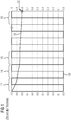
- the representation in FIG. 1 represents a sequence of discharge cycles and subsequent charge cycles for the respective complete discharge and subsequent complete charge (full charge cycle).
- a rectangularly drawn first curve 10 represents over the time plotted on the abscissa the respective state of charge of the battery (state-of-charge / SoC) On the ordinate for a 0.0 to 1.0 normalized state of charge is plotted.
- a first charge cycle 12 a second charge cycle 14, a third charge cycle 16 and finally an nth charge cycle 18, that is, for example, a five hundredth charge cycle 18, are depicted.
- the second curve 20 the resulting battery aging (state of health / SoH). For the point 22 indicated by the arrow it is assumed that a battery replacement is required.
- a first curve 10 again represents the state of charge of the battery (state-of-charge / SoC) plotted over time.
- the individual partial charge cycles 24 are symmetrical, that is to say that a partial discharge 26 is always followed by an equal charge, so that at the end of each partial charge cycle 24, the battery is fully charged.
- the discharge 26 is illustrated by downward arrows whose length is a measure of the respective discharge D od .
- a disadvantage of this approach is the limitation to symmetrical partial charging cycles, in which with the discharge and the subsequent charging of the battery in terms of amount exactly that portion of energy is returned, which was previously removed during the discharge. In reality this is often not the case since a charge does not necessarily exactly compensate for a previous discharge of the battery. Also, an aging metric can not be derived directly from the partial load cycles, since these are designed differently for each discharge depth D od .
- the Indian EP 1 450 173 A2 The approach presented tries to take this into account by dividing a subcycle into a partial loading cycle and a partial unloading cycle. Asymmetric partial cycles can also be described with which a discharge and a subsequent charge of the battery can vary in strength.
- the basis of the aging calculation are aging characteristics A ki , which are to be determined for a defined discharge depth D od of the battery.
- a relationship between an aging characteristic A ki and a discharge depth D od is defined by a battery-dependent characteristic curve / value table to be determined. How such a characteristic / value table is to be determined in detail is described in the EP 1 450 173 A2 not explained in detail.
- a ki is the aging characteristic of the battery for a defined depth of discharge D od, i , D od, i the occurred depth of discharge in the i-th cycle
- n i the number of partial charge cycles and partial discharge cycles with a constant discharge depth
- N pc the number of partial charge cycles and partial discharge cycles represent with different depth of discharge.
- the battery aging A (Equation 3) that can be determined in this way represents an absolute characteristic number that can not be compared directly with the relative battery aging according to Equation 1.
- the main disadvantages of this approach are that the aging A of the battery can be evaluated in a discrete-time manner only after a partial charging cycle or partial discharge cycle by evaluating a predetermined value table or characteristic curve. An evaluation of the aging at any time even within the charge and discharge cycles is therefore not possible.
- the relationship between the discharge depth D od and the aging index A ki (for example, by means of measurement series for each discharge depth D od to be considered) must be determined in advance in a complex manner for each type of battery. This further leads to Diskretmaschineshoun, since not as many measurement series for the determination of the characteristic makes sense can be performed and at least the table of values or characteristic can not be maintained arbitrarily detailed for a device for determining the battery aging.
- the advantage of the invention on the basis of these disadvantages of the prior art, is that a method can be specified with the aid of which a relative aging of the battery on the basis of the battery current i B (t) at any time, in particular also within partial charging cycles or partial discharge cycles, can be determined.
- Equation 4 a metric presented below in Equation 4 is proposed, which can continuously determine battery relative aging based on battery current i B (t).
- a (t) is an aging number of the battery at time t
- N fc is a number of full charge cycles of the battery specified by the respective battery manufacturer at a constant charge and discharge current I BO
- I BO of the battery power specified by the battery manufacturer at which N fc full charge cycles are guaranteed
- B (t) is the battery electric current
- C B is the capacity of the battery in [Ah]
- ⁇ is an adaptation parameter ( ⁇ > 1) for different battery technologies
- the aging number A (t) is also referred to below as battery aging A (t).
- Equation 4 is the quantitative description of the battery aging on the basis of a respective battery current i B (t) mentioned above in connection with the summary of the solution proposed here of the problem formulated above.
- the battery current i B (t) can be detected continuously within a so-called BMU (Battery Management Unit) of a battery, the battery aging during operation can be evaluated at any time with the aid of this metric.
- BMU Battery Management Unit
- the respectively determined according to the equation 4 aging A (t) directly provides information about the battery aging and / or a possibly necessary replacement of the battery.
- a predetermined or specifiable function ⁇ (i B ) flows into the determination of the battery aging according to Equation 4 in order to take account of the influence of the current intensity i B (t) on the battery aging.
- the method as described here and below is particularly suitable for use in connection with a unit or device for battery management (battery management unit).
- the method for determining the battery aging in particular the equation 4 proposed to that extent, is implemented in software or in software and hardware or firmware.
- the invention is therefore on the one hand, for example, a computer program with executable by a computer program code instructions and on the other hand, a storage medium with such a computer program, and finally also such a battery management unit with a processing unit in the form of or a kind of microprocessor and a memory, in as Means for performing the method and its embodiments such a computer program is loaded or loadable.
- a processing unit in the form of a so-called ASIC or the like the implementation of the method is part of the ASIC; Processing unit and memory so to speak coincide.
- Such a battery management unit and a battery management executed by the latter as a result of the method are particularly suitable for use in or in connection with a driver assistance system for battery-powered vehicles or so-called hybrid vehicles with an electric motor and an internal combustion engine, wherein the battery management unit is connected to the respective driver assistance system information about battery aging transmitted continuously or at predetermined or predeterminable times.
- the driver assistance system is thus informed about the status of the battery aging and can implement this information, for example, in a display for the respective driver.
- Such an ad can continuously map the respective status of the battery aging or, alternatively, be activated only when a predetermined or predefinable critical value is reached with respect to the battery aging.
- a driver assistance system which uses the information received for battery aging to indicate to a driver the respective battery aging, it is considered to be a special embodiment that such a display together with instructions with regard to a relationship of a particular driving style and a resulting battery aging and / or with hints in With regard to a battery-saving driving style.
- the advantage of the invention and its embodiments is thus in particular the return of the battery aging on the battery current, which can be evaluated continuously for an aging metric. This discretization errors are avoided as they z. B. occur in processes that are based on tables of values or characteristics. Assistance systems, for example for so-called smart meter applications, also require continuous monitoring of battery aging in order to balance the use of electric machines with a view to minimizing battery aging.
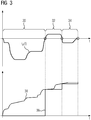
- FIG. 3 an exemplary, but in principle realistic representation of discharging and charging of a battery, as they are, for example, when using a such battery in an electric vehicle or a hybrid vehicle results.
- the time t is plotted on the abscissa.
- the upper illustration shows a profile of a battery current i B (t) in amperes.
- a discharge of the battery takes place.
- the battery current i B (t) above the abscissa, ie in the positive range runs, the battery is charged.
- the course of the battery current i B (t) can thus be subdivided into a discharge subcycle 30, a charge subcycle 32 and a further discharge subcycle 34, hereinafter referred to individually and together as subcycle or subcycles.
- a determined battery aging A (t) is shown in the lower part of FIG. 3 .
- a first graph 36 provides for comparison purposes after the in the EP 1 450 173 A It is noticeable that the battery aging can only be determined during the transition from a charge or discharge cycle to the subsequent discharge or charge cycle, and that within such partial cycles 30, 32, 34 continue from last calculated value for the battery aging must be assumed.
- a second graph 38 is a representation of a battery aging A (t) determined according to equation 4 as a function of that in the upper illustration in FIG. 3 shown course of the battery current i B (t). It is readily apparent that the approach proposed here for determining the battery aging provides a continuous or, in the case of a customary sampling of the battery current i B (t), at least a quasi-continuous and thus altogether better usable and more reliable statement with regard to battery aging.
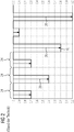
- FIG. 4 shows a graphical comparison of the approach according to the EP 1 450 173 A and the approach presented here.
- the approach according to the EP 1 450 173 A is shown on the left side.
- a subsequent second step 42 is required for the identification of a subcycle, because only at the boundaries of such subcycles ( FIG. 3 : 30, 32, 34), the battery aging can be determined using this approach.
- the discharge depth D od is determined in the respective subcycle.
- step 46 the evaluation of the characteristic curve / value table determined in the first step 40 can take place and an aging characteristic value A ki can be determined as a function of the determined discharge depth D od : A ki (D od ).
- this aging characteristic A ki can be used to apply the metric according to Equation 3 and the battery aging A can be determined as a function of the aging characteristic A ki : A (A ki ).
- the battery aging A thus determined is also, in a way, a time-dependent representation of the battery aging, without, however, really allowing a continuous presentation of the battery aging.
- the second, third, fourth, and fifth steps 42-48 are executed continuously.
- identification of a subcycle is at the end of the process a statement regarding the aging A of the battery at the end of the just identified subcycle (sixth step 50).
- the method proposed here is not only simpler, but also provides continuous or quasi-continuous values for the aging A (t) of the battery independently of partial cycles or transitions from one subcycle to a subsequent subcycle.
- the process comprises ( FIG. 4 , right side) in the illustrated abstraction only three steps, namely a first, second and third step 52, 54, 56.
- an evaluation of the metric according to equation 4 is carried out for the respectively measured battery current i B (t): A (i B ).
- an aging A (t) of the respective battery results at any desired time t.
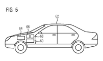
- the method proposed here is particularly suitable for determining the aging A (t) of a battery 60, as provided in a conventional manner, for example in an electric or hybrid vehicle 62 for driving an electric motor 64 or other consumer (not shown) ( FIG. 5 ).
- a battery management unit 66 possibly a battery management unit 66 in combination with a subsequent unit, for example, a driver assistance system 68, provided in FIG. 6 is shown with further details.
- FIG. 6 shows accordingly in a simplified schematic representation, on the one hand, the battery 60 and the other hand, the battery management unit 66.
- This detects continuously or quasi-continuously the battery current i B (t) - Measurement of the battery current i B (t); first step 52 ( FIG. 4 ).
- the battery management unit 66 comprises a sensor system, which is not shown in any more detail, or is suitably connected to such a sensor, so that it is possible to record corresponding measured values.
- the battery management unit 66 comprises a processing unit 70 in the form of or in the manner of a microprocessor and a memory 72.
- a further computer program 74 is loaded into the memory 72 as a further means for executing the method, which program code instructions for implementing the method and, if necessary. single or multiple embodiments as described herein, specifically for implementing the above-mentioned Equation 4.
- an aging A (t) of the battery 60 is determined and either a corresponding value, which can be processed by a subsequent unit, for example a driver assistance system 68, is output and / or an actuator 76 is actuated in accordance with the respectively determined aging A (t) , for example, a display in a dashboard of the vehicle 62.
- the battery management unit 66 On the basis of measurement data, namely the battery current i B (t), determined battery aging A (t).
- This usually comprises itself a processing unit 78 and a memory 80 with at least one computer program 82 as described above.
- the computer program 74 of the battery management unit 66 may also be referred to as the battery management computer program and the computer program 82 of the driver assistance system 68 as the driver assistance system computer program 82.
- the information about the respective battery aging A (t) enables the driver assistance system 68 with a corresponding functionality implemented in the form of the computer program 82 or a part of the computer program 82 to make proposals to the driver for a battery-saving driving behavior and thus to increase the battery life and reduce operating costs. These suggestions are brought to the attention of the driver in the form of a corresponding control of an actuator 84.
- the actuator 84 may be, for example, a display element in the manner of a light-emitting diode or the like, for example by Color change to indicate an unfavorably high acceleration.
- the actuator 84 may also be a display device that allows an output of at least short text messages or the like, as is known from today's on-board computers commonly used in vehicles.
- a driver assistance system 68 may also propose a battery-saving driving of the vehicle 62 and / or charging of the battery 60.
- the battery aging A (t) can also be predicted assuming different battery currents i B (t) and expected operating costs can be determined on this basis.
- Such predictions and cost estimates are also applicable in an alternative application scenario for cost control of use of single or multiple batteries as energy buffers (energy buffers) in the context of so-called smart grid applications.
- the influence of varying battery currents i B (t) within a charging cycle for example charging with varying charging current from regenerative energy sources) or discharging cycle (discharging by varying current loads of consumers) on the battery aging can then be taken into account and evaluated financially.
- Continuous monitoring of battery aging in combination with a connection to a cloud application also allows centralized management and control of batteries.
- a cloud application for example via UMTS / LAN
- the various aging of battery clusters can be monitored continuously and their use can be controlled in a battery-saving manner.
- the method proposed here can be used to continuously determine and store the battery aging while driving - ie within a subcycle - in order to characterize a route with respect to the aging process of the battery.
- a route for example due to many ascents and descents, causes a higher battery aging and thus higher operating costs than another route in which such loads do not occur.
- This information can then be used, for example, for a vehicle navigation solution in order to optimize a route planning with regard to a way to the battery-saving driving style as possible.
- This application is also very well suited for a cloud connection, which collects such information centrally and then provides electric vehicles, for example, as a navigation service.
Landscapes
- Physics & Mathematics (AREA)
- General Physics & Mathematics (AREA)
- Secondary Cells (AREA)
- Charge And Discharge Circuits For Batteries Or The Like (AREA)
Priority Applications (1)
| Application Number | Priority Date | Filing Date | Title |
|---|---|---|---|
| EP12156563.4A EP2631663A1 (fr) | 2012-02-22 | 2012-02-22 | Procédé de surveillance continue du vieillissement d'une batterie |
Applications Claiming Priority (1)
| Application Number | Priority Date | Filing Date | Title |
|---|---|---|---|
| EP12156563.4A EP2631663A1 (fr) | 2012-02-22 | 2012-02-22 | Procédé de surveillance continue du vieillissement d'une batterie |
Publications (1)
| Publication Number | Publication Date |
|---|---|
| EP2631663A1 true EP2631663A1 (fr) | 2013-08-28 |
Family
ID=45656458
Family Applications (1)
| Application Number | Title | Priority Date | Filing Date |
|---|---|---|---|
| EP12156563.4A Withdrawn EP2631663A1 (fr) | 2012-02-22 | 2012-02-22 | Procédé de surveillance continue du vieillissement d'une batterie |
Country Status (1)
| Country | Link |
|---|---|
| EP (1) | EP2631663A1 (fr) |
Cited By (10)
| Publication number | Priority date | Publication date | Assignee | Title |
|---|---|---|---|---|
| CN111830411A (zh) * | 2020-06-15 | 2020-10-27 | 联合汽车电子有限公司 | 车用蓄电池老化控制系统及交通工具 |
| US20210328274A1 (en) * | 2019-10-31 | 2021-10-21 | Sion Power Corporation | System and method for operating a rechargeable electrochemical cell or battery |
| CN113875063A (zh) * | 2019-04-17 | 2021-12-31 | Avl李斯特有限公司 | 针对用于保护电池装置的保护方法进行检查的方法 |
| DE102020212278A1 (de) | 2020-09-29 | 2022-03-31 | Robert Bosch Gesellschaft mit beschränkter Haftung | Verfahren und Vorrichtung zur maschinenindividuellen Verbesserung der Lebensdauer einer Batterie in einer batteriebetriebenen Maschine |
| CN115219930A (zh) * | 2022-03-29 | 2022-10-21 | 广州汽车集团股份有限公司 | 车辆蓄电池老化预警方法、装置、电子设备以及存储介质 |
| US11990589B2 (en) | 2019-10-31 | 2024-05-21 | Sion Power Corporation | System and method for operating a rechargeable electrochemical cell or battery |
| US12374913B2 (en) | 2021-02-05 | 2025-07-29 | Sion Power Corporation | Charge/discharge management in electrochemical cells, including partial cycle control |
| US12567752B2 (en) | 2018-07-31 | 2026-03-03 | Sion Power Corporation | Multiplexed charge discharge battery management system |
| US12580394B2 (en) | 2020-09-01 | 2026-03-17 | Sion Power Corporation | Multiplexed battery management system |
| US12613286B2 (en) | 2024-01-22 | 2026-04-28 | Garrett Transportation I Inc. | System and method for battery parameter recharacterization |
Citations (4)
| Publication number | Priority date | Publication date | Assignee | Title |
|---|---|---|---|---|
| US5703469A (en) * | 1995-06-05 | 1997-12-30 | Honda Giken Kogyo Kabushiki Kaisha | System for determining battery conditions |
| EP1450173A2 (fr) | 2003-02-24 | 2004-08-25 | DaimlerChrysler AG | Méthode pour l'évaluation d'une dégradation d'une batterie |
| DE10328721A1 (de) * | 2003-06-25 | 2005-01-13 | Robert Bosch Gmbh | Verfahren zur Vorhersage einer Restlebensdauer eines elektrischen Energiespeichers |
| DE102010031337A1 (de) * | 2010-07-14 | 2012-01-19 | Sb Limotive Company Ltd. | Verfahren zur Ermittlung der voraussichtlichen Lebensdauer wenigstens einer Batteriezelle, Batterie mit einer Mehrzahl von Batteriezellen und Kraftfahrzeug |
-
2012
- 2012-02-22 EP EP12156563.4A patent/EP2631663A1/fr not_active Withdrawn
Patent Citations (4)
| Publication number | Priority date | Publication date | Assignee | Title |
|---|---|---|---|---|
| US5703469A (en) * | 1995-06-05 | 1997-12-30 | Honda Giken Kogyo Kabushiki Kaisha | System for determining battery conditions |
| EP1450173A2 (fr) | 2003-02-24 | 2004-08-25 | DaimlerChrysler AG | Méthode pour l'évaluation d'une dégradation d'une batterie |
| DE10328721A1 (de) * | 2003-06-25 | 2005-01-13 | Robert Bosch Gmbh | Verfahren zur Vorhersage einer Restlebensdauer eines elektrischen Energiespeichers |
| DE102010031337A1 (de) * | 2010-07-14 | 2012-01-19 | Sb Limotive Company Ltd. | Verfahren zur Ermittlung der voraussichtlichen Lebensdauer wenigstens einer Batteriezelle, Batterie mit einer Mehrzahl von Batteriezellen und Kraftfahrzeug |
Non-Patent Citations (1)
| Title |
|---|
| WORKING PAPER SUSTAINABILITY AND INNOVATION, pages 12 - 13 |
Cited By (16)
| Publication number | Priority date | Publication date | Assignee | Title |
|---|---|---|---|---|
| US12567752B2 (en) | 2018-07-31 | 2026-03-03 | Sion Power Corporation | Multiplexed charge discharge battery management system |
| CN113875063A (zh) * | 2019-04-17 | 2021-12-31 | Avl李斯特有限公司 | 针对用于保护电池装置的保护方法进行检查的方法 |
| US20210328274A1 (en) * | 2019-10-31 | 2021-10-21 | Sion Power Corporation | System and method for operating a rechargeable electrochemical cell or battery |
| US11990589B2 (en) | 2019-10-31 | 2024-05-21 | Sion Power Corporation | System and method for operating a rechargeable electrochemical cell or battery |
| US11658352B2 (en) * | 2019-10-31 | 2023-05-23 | Sion Power Corporation | System and method for operating a rechargeable electrochemical cell or battery |
| CN111830411A (zh) * | 2020-06-15 | 2020-10-27 | 联合汽车电子有限公司 | 车用蓄电池老化控制系统及交通工具 |
| CN111830411B (zh) * | 2020-06-15 | 2024-04-26 | 联合汽车电子有限公司 | 车用蓄电池老化控制系统及交通工具 |
| US12580394B2 (en) | 2020-09-01 | 2026-03-17 | Sion Power Corporation | Multiplexed battery management system |
| US11835589B2 (en) | 2020-09-29 | 2023-12-05 | Robert Bosch Gmbh | Method and apparatus for machine-individual improvement of the lifetime of a battery in a battery-operated machine |
| CN114312479A (zh) * | 2020-09-29 | 2022-04-12 | 罗伯特·博世有限公司 | 机器特定地改善电池驱动机器中电池使用寿命的方法和装置 |
| EP3978306A1 (fr) * | 2020-09-29 | 2022-04-06 | Robert Bosch GmbH | Procédé et dispositif d'amélioration spécifique à une machine de la durée de vie d'une batterie dans une machine fonctionnant sur batterie |
| DE102020212278A1 (de) | 2020-09-29 | 2022-03-31 | Robert Bosch Gesellschaft mit beschränkter Haftung | Verfahren und Vorrichtung zur maschinenindividuellen Verbesserung der Lebensdauer einer Batterie in einer batteriebetriebenen Maschine |
| US12374913B2 (en) | 2021-02-05 | 2025-07-29 | Sion Power Corporation | Charge/discharge management in electrochemical cells, including partial cycle control |
| CN115219930B (zh) * | 2022-03-29 | 2024-04-19 | 广州汽车集团股份有限公司 | 车辆蓄电池老化预警方法、装置、电子设备以及存储介质 |
| CN115219930A (zh) * | 2022-03-29 | 2022-10-21 | 广州汽车集团股份有限公司 | 车辆蓄电池老化预警方法、装置、电子设备以及存储介质 |
| US12613286B2 (en) | 2024-01-22 | 2026-04-28 | Garrett Transportation I Inc. | System and method for battery parameter recharacterization |
Similar Documents
| Publication | Publication Date | Title |
|---|---|---|
| EP2631663A1 (fr) | Procédé de surveillance continue du vieillissement d'une batterie | |
| DE102012207815B4 (de) | Systeme und verfahren zum bestimmen von zellenkapazitätswerten in einer batterie mit vielen zellen | |
| DE102012214962B4 (de) | Verfahren zum Berechnen der verbleibenden Fahrstrecke für ein Elektrofahrzeug | |
| EP4222513B1 (fr) | Détermination de l'état de santé d'une batterie de véhicule | |
| EP2531869B1 (fr) | Dispositif et procédé pour déterminer une zone d'une ligne caractéristique de batterie | |
| DE102015109301B4 (de) | Verfahren zur bestimmung und anzeige eines energieverbrauchsparameters | |
| DE102015203789A1 (de) | Batteriemodell mit Robustheit gegenüber cloud-spezifischen Kommunikationsproblemen | |
| DE102015107930A1 (de) | Schätzung und Ausgleich von Batteriemessungen | |
| DE102011119061A1 (de) | Batteriediffusionsspannungsschätzung | |
| DE102017002483A1 (de) | Technik zur Isolationsüberwachung in Fahrzeugen | |
| EP2902243B1 (fr) | Procédé et dispositif d'affichage de paramètres de véhicule | |
| DE102012007988A1 (de) | Verfahren und Vorrichtung zur Visualisierung der Leistungsdynamik der Batterie eines elektrisch angetriebenen Fahrzeugs | |
| DE102020214389A1 (de) | Verfahren und Vorrichtung zur Bestimmung eines Alterungszustands einer Gerätebatterie unbekannten Typs für ein batteriebetriebenes elektrisches Gerät | |
| DE102011012818B4 (de) | Verfahren und Vorrichtung zum Betreiben einer Batterie für ein Fahrzeug und entsprechendes Fahrzeug | |
| DE102017200548A1 (de) | Verfahren zur Ermittlung einer aktuellen Kennlinie für einen ein Kraftfahrzeug versorgenden elektrochemischen Energiespeicher, Kraftfahrzeug und Server | |
| DE102018005566A1 (de) | Verfahren für das Bestimmen einer Reichweite eines Kraftwagens sowie Vorrichtung für das Bestimmen einer Reichweite | |
| DE102019129902B4 (de) | Verfahren und system zum vorhersagen einer motorstart-performance eines elektrischen energiespeichersystems | |
| EP4323229B1 (fr) | Dispositif de gestion d'énergie et procédé de fourniture d'une valeur d'énergie estimée d'une batterie | |
| EP1901081A1 (fr) | Dispositif et procédé destinés à la transmission de l'état d'une batterie | |
| DE102012022458A1 (de) | Verfahren und System zum Überwachen eines Energiespeichers sowie ein elektrisch angetriebenes Kraftfahrzeug mit einer derartigen Energiespeicherüberwachung | |
| EP3366506B1 (fr) | Technique de surveillance de l'isolement des véhicules | |
| DE102008053604A1 (de) | Vorrichtung zur Bewertung des Fahrzustands eines Hybridfahrzeuges | |
| DE102021115534A1 (de) | Verfahren zum Ermitteln einer Batterieimpedanz, Messeinrichtung und Kraftfahrzeug | |
| DE102020214180A1 (de) | Verfahren und Vorrichtung zum Bestimmen einer Zustandsgröße eines elektrischen Energiespeichers | |
| DE102018219124A1 (de) | Verfahren zum Ermitteln eines Verschleißzustands eines elektrischen Energiespeichers in einem Kraftfahrzeug sowie Steuervorrichtung zum Durchführen des Verfahrens und Kraftfahrzeug |
Legal Events
| Date | Code | Title | Description |
|---|---|---|---|
| PUAI | Public reference made under article 153(3) epc to a published international application that has entered the european phase |
Free format text: ORIGINAL CODE: 0009012 |
|
| AK | Designated contracting states |
Kind code of ref document: A1 Designated state(s): AL AT BE BG CH CY CZ DE DK EE ES FI FR GB GR HR HU IE IS IT LI LT LU LV MC MK MT NL NO PL PT RO RS SE SI SK SM TR |
|
| AX | Request for extension of the european patent |
Extension state: BA ME |
|
| STAA | Information on the status of an ep patent application or granted ep patent |
Free format text: STATUS: THE APPLICATION IS DEEMED TO BE WITHDRAWN |
|
| 18D | Application deemed to be withdrawn |
Effective date: 20140301 |