EP2631382A2 - Step and work platform - Google Patents
Step and work platform Download PDFInfo
- Publication number
- EP2631382A2 EP2631382A2 EP13156278.7A EP13156278A EP2631382A2 EP 2631382 A2 EP2631382 A2 EP 2631382A2 EP 13156278 A EP13156278 A EP 13156278A EP 2631382 A2 EP2631382 A2 EP 2631382A2
- Authority
- EP
- European Patent Office
- Prior art keywords
- base plate
- stepping
- working platform
- profile
- platform
- Prior art date
- Legal status (The legal status is an assumption and is not a legal conclusion. Google has not performed a legal analysis and makes no representation as to the accuracy of the status listed.)
- Granted
Links
Images


Classifications
-
- E—FIXED CONSTRUCTIONS
- E04—BUILDING
- E04D—ROOF COVERINGS; SKY-LIGHTS; GUTTERS; ROOF-WORKING TOOLS
- E04D15/00—Apparatus or tools for roof working
-
- E—FIXED CONSTRUCTIONS
- E04—BUILDING
- E04D—ROOF COVERINGS; SKY-LIGHTS; GUTTERS; ROOF-WORKING TOOLS
- E04D13/00—Special arrangements or devices in connection with roof coverings; Protection against birds; Roof drainage ; Sky-lights
- E04D13/12—Devices or arrangements allowing walking on the roof or in the gutter
-
- F—MECHANICAL ENGINEERING; LIGHTING; HEATING; WEAPONS; BLASTING
- F24—HEATING; RANGES; VENTILATING
- F24S—SOLAR HEAT COLLECTORS; SOLAR HEAT SYSTEMS
- F24S40/00—Safety or protection arrangements of solar heat collectors; Preventing malfunction of solar heat collectors
-
- Y—GENERAL TAGGING OF NEW TECHNOLOGICAL DEVELOPMENTS; GENERAL TAGGING OF CROSS-SECTIONAL TECHNOLOGIES SPANNING OVER SEVERAL SECTIONS OF THE IPC; TECHNICAL SUBJECTS COVERED BY FORMER USPC CROSS-REFERENCE ART COLLECTIONS [XRACs] AND DIGESTS
- Y02—TECHNOLOGIES OR APPLICATIONS FOR MITIGATION OR ADAPTATION AGAINST CLIMATE CHANGE
- Y02B—CLIMATE CHANGE MITIGATION TECHNOLOGIES RELATED TO BUILDINGS, e.g. HOUSING, HOUSE APPLIANCES OR RELATED END-USER APPLICATIONS
- Y02B10/00—Integration of renewable energy sources in buildings
- Y02B10/20—Solar thermal
-
- Y—GENERAL TAGGING OF NEW TECHNOLOGICAL DEVELOPMENTS; GENERAL TAGGING OF CROSS-SECTIONAL TECHNOLOGIES SPANNING OVER SEVERAL SECTIONS OF THE IPC; TECHNICAL SUBJECTS COVERED BY FORMER USPC CROSS-REFERENCE ART COLLECTIONS [XRACs] AND DIGESTS
- Y02—TECHNOLOGIES OR APPLICATIONS FOR MITIGATION OR ADAPTATION AGAINST CLIMATE CHANGE
- Y02E—REDUCTION OF GREENHOUSE GAS [GHG] EMISSIONS, RELATED TO ENERGY GENERATION, TRANSMISSION OR DISTRIBUTION
- Y02E10/00—Energy generation through renewable energy sources
- Y02E10/40—Solar thermal energy, e.g. solar towers
-
- Y—GENERAL TAGGING OF NEW TECHNOLOGICAL DEVELOPMENTS; GENERAL TAGGING OF CROSS-SECTIONAL TECHNOLOGIES SPANNING OVER SEVERAL SECTIONS OF THE IPC; TECHNICAL SUBJECTS COVERED BY FORMER USPC CROSS-REFERENCE ART COLLECTIONS [XRACs] AND DIGESTS
- Y02—TECHNOLOGIES OR APPLICATIONS FOR MITIGATION OR ADAPTATION AGAINST CLIMATE CHANGE
- Y02E—REDUCTION OF GREENHOUSE GAS [GHG] EMISSIONS, RELATED TO ENERGY GENERATION, TRANSMISSION OR DISTRIBUTION
- Y02E10/00—Energy generation through renewable energy sources
- Y02E10/50—Photovoltaic [PV] energy
Definitions
- the invention relates to a treadmill and work platform for resting on at least one solar module mounted in an oblique angle of a solar system.
- a solar system usually consists of a large number of individual solar modules, which to a large area, z. B. are assembled on a roof of a building.
- photovoltaic systems and solar thermal systems are generally referred to as a solar system.
- the individual solar modules have a glass pane or the like on their surface or at least have a light-permeable cover layer. The surface of such solar modules is relatively sensitive and should therefore be entered neither during assembly nor during maintenance of the solar system.
- a stepping and working platform is specified for resting on at least one solar module of a solar system mounted at an oblique angle.
- the solar system is a photovoltaic system.
- the tread and work platform can also be used for solar thermal systems, which are constructed of individual flat solar modules.
- the designed according to aspects of the invention treadmill and work platform comprises a base plate and a detent attached thereto for securing the tread and working platform relative to the Solar module.
- the lock extends along an edge of the base plate and has a stop surface. This stop surface protrudes out of a plane spanned by the base plate of the tread and work platform level.
- the abutment surface is intended to come with an overhead edge of the mounted in an oblique angle solar module non-positively and / or positively to the stop.
- the treadmill and work platform can be placed according to aspects of the invention on a solar module of a solar system, the mechanical loads occurring on entering the treadmill and work platform are distributed over a large area on the underlying solar module. The risk of damaging the solar module can thus be minimized.
- the individual solar modules large-scale solar systems are mounted leaving a gap between the individual solar modules to allow thermal expansion of the solar modules. The width of this gap is predetermined by the thermal expansion of the solar modules when heated.
- the lock engages from the top of the solar modules forth in this gap. Since the abutment surface of the locking force and preferably also positively abuts a gap adjacent to the upper edge of the relevant solar module, slippage of the tread and work platform can be effectively avoided.
- This stop surface preferably extends in the direction of an underside of the tread and working platform out of a plane spanned by the base plate. Further preferably, the stop surface is oriented substantially perpendicular to the base plate. This allows easy handling of the platform and work platform, which can be placed on a solar module or lifted off it with a few simple steps.
- the entire surface of the solar system is easily accessible, with a first treadle and work platform serving as a stand space, while a second tread and work platform is used from a previous one next solar module is implemented.
- a service technician or a cleaning person can easily reach any point of a solar system.
- the use of complex and expensive cranes can be advantageously dispensed with.
- the treadmill and work platform on at least one of the flat sides of the base plate at least in sections, preferably over the entire surface, an elastic layer.
- the elastic layer is mounted on the bottom of the tread and work platform formed by a flat side of the base plate.
- the risk of damage to the surface of the solar modules can be further minimized.
- the existing between the elastic layer and the surface of the solar modules static friction additionally prevents slippage of the tread and work platform.
- sponge rubber could be found. It has been found that a glued to the base plate layer of sponge rubber, z. As a foam rubber made of cellular rubber ZK100, is particularly suitable.
- the rail can be used as a locking at least partially along the edge of the base plate extending rail.
- the rail for example, aluminum but also plastic is suitable.
- this rail is embedded in at least one of the flat sides of the base plate.
- protruding edges can be avoided, which minimizes the risk of damage to the solar panels and the risk of injury to the user.
- the profile rail is preferably an at least partially L-shaped profile.
- the profile rail is to be considered in a cross-section oriented perpendicular to the upper edge.
- the stop surface of the lock is formed by a leg of such an L-profile.
- the profile rail viewed in a cross-section oriented perpendicular to the upper edge, has an F-profile.
- This F-profile has a U-shaped area for receiving the base plate.
- the base plate thus extends into this U-shaped region of the F-profile and is connected in this area with the rail, for example by screws.
- the F-profile rail also has a transverse to the flat sides of the base plate oriented leg, through which the stop surface is formed.
- this stop surface is oriented perpendicular to the flat sides of the base plate, wherein in this context, a perpendicular to the upper edge oriented cross-section is considered.
- a foam board is particularly suitable. Such materials are lightweight and withstand high loads.
- a glass fiber reinforced polyurethane foam board is used. This material is strong and light enough at the same time, so that the platform and work platform is easy to handle.
- this material is UV-resistant and waterproof and thus particularly suitable for outdoor use, especially in cleaning of solar modules.
- the treadmill and working platform is larger in a longitudinal direction than in a transverse (preferably substantially perpendicular) oriented transverse direction.
- the locking of the tread and work platform extends in this embodiment along a transverse edge of the base plate.
- the base plate is rectangular, which is particularly advantageous when using multiple tread and work platforms, which are added during the operation. Due to the elongated shape of the treadmill and work platform, a previously used further treadmill and work platform can be accommodated in a lower area of the currently used treadmill and work platform and placed on top of another solar module. Since the tread and work platform is large in the longitudinal direction, a large work path can be traveled on a single tread and work platform, making work efficient.
- a flat side of the base plate which is not provided with an elastic layer, at least in sections, preferably over the entire surface, provided with a non-slip layer.
- a non-slip surface significantly reduces the risk of falling even when wet.
- a two-component epoxy coating with interspersed, annealed, pure quartz sand can be used for the non-slip coating.
- the height by which the stop surface protrudes from the underside of the tread and work platform is less than or equal to a thickness of the tread and work platform in the region of the base plate.
- tread and work platforms can be stacked with pairs of superimposed sides, without causing a cross or high offset of the stack. The respective stop surfaces do not protrude beyond the adjacent plate in the stacked state.
- Such kick and Work platform can be transported and stored efficiently and space-saving.
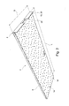
- FIG. 1 shows a simplified perspective view of a tread and work platform 2 from the top 4, according to one embodiment.
- the stepping and working platform 2 comprises a base plate 6 which is rectangular in plan view.
- the base plate 6 of the stepping and working platform 2 consists of a hard foam material, for example, a glass fiber reinforced rigid polyurethane foam board (eg., The type: Thermo Lite Board Series 2816) is used with a thickness of 19 mm.
- foam board is made of 85.6% rigid polyurethane foam and has a share of 14.4% glass fibers.
- foam boards can be used with a greater strength, for example, if they are to be designed for greater loads. According to the in FIG.
- the base plate 6 of the treading and working platform 2 has a compressive strength of 2.5% deformation at a load of 32 kg / cm 2 .
- the bending strength is preferably 377 kg / cm 2 , the yield stress at 302 kg / cm 2 .
- the treadmill and work platform 2 has at a top edge 8, which extends in a transverse direction of the base plate 6, a lock 10.
- This lock 10 consists of a sectionally mounted on the upper edge 8 aluminum F-profile with a leg length of preferably 60 mm.
- the detent 10 consists of two separate and along the upper edge 8 spaced F-profile pieces. Of course, a continuous profile, which extends along the entire upper edge 8, are used.
- the upper side 4 of the base plate 6 is provided with a non-slip coating, which preferably consists of a two-component epoxy coating with interspersed, annealed, pure quartz sand.
- this has a recessed into the base plate 6 handle 12. In the vicinity of a lower edge of the base plate 6 is also a nameplate 13th
- FIG. 2 shows the off FIG. 1 known treadmill and working platform 2 in a further perspective view from its bottom 14.
- the treadmill and working platform 2 has a length L of 1502mm and a transverse width Q of 500 mm.
- other dimensions of the working platform 2 can be realized depending on the customer.
- an elastic layer 16 is applied to the base plate 6, which consists for example of a sponge rubber.
- a preferred material for this sponge rubber is ZK100 cellular rubber.
- the elastic layer 16 is glued to the lower flat side of the base plate 6.
- the elastic layer 16 extends over the entire surface on the underside 14 of the tread and work platform 2.
- an F-profile lock 10 has in addition to the FIG. 1 well visible upper mounting legs 18 holding legs 20, which extend from a plane spanned by the base plate 6 in the direction of the bottom 14 of the tread and work platform 2, and a stop surface 22 on its in FIG. 2 form the opposite side.
- This stop surface 22 is intended to positively abut against an upper edge of a solar module, so that slipping of the tread and work platform 2 can be effectively avoided.
- FIG. 3 shows a simplified perspective detail view of the treadmill and work platform 2 in the region of its upper edge 8.
- the consisting of an F-shaped profile lock 10 extends along the upper edge 8 of the tread and work platform 2. It is preferably in the F-. shaped profile around an aluminum profile. However, it can also be used a suitable plastic profile.
- the consisting of the F-profile lock 10 has an upper mounting leg 18 which rests on the top 4 of the base plate 6 and different from the illustration in FIG. 3 can be embedded in this.
- the F-profile comprises a lower mounting leg 19, which rests on a lower flat side of the base plate 6. Of course, this lower mounting leg 19 may be inserted differently from the representation in the base plate 6.
- the upper and lower mounting legs 18, 19 form a U-profile, in which the base plate 6 extends into it.
- the lock 10 is fixed to the base plate 6 in this area.
- screws 26, z. B. countersunk screws (see also FIG. 5 ), which engage from the upper mounting leg 18 through the base plate 6 through into the lower mounting leg 19 is used.
- the detent 10, ie the F-profile, also has a retaining leg 20, which extends substantially perpendicular to the flat sides of the base plate 6, as far as in FIG. 3 the relevant area of the tread and work platform 2 is viewed in a cross section which is perpendicular to the upper edge 8.
- the holding leg 20 forms a stop surface 22, which force when using the treadle and working platform 2 on a solar module of a solar system with an upper edge of a corresponding solar module and preferably also comes positively to the stop.
- the elastic layer 16 On its underside 14, the treadmill and working platform 2, the elastic layer 16, which preferably consists of sponge rubber.
- the frictionally fitting abutment surface 22 prevents together with the friction occurring between the sponge rubber and the surface of the solar modules slipping off the tread and work platform 2.
- the base plate 6 On the top 4 of the tread and work platform 2, the base plate 6 is provided with a non-slip coating 24 which preferably consists of a two-component epoxy resin coating with interspersed quartz sand.
- the locking profile 10 serving F-profile preferably has a leg length of 60 mm, with a 2 mm thick aluminum profile can be used.
- the thickness of the rigid foam plate used as the base plate 6 is preferably 19 mm.
- the elastic layer located on the underside 14 is preferably 8 mm thick. Of course, other dimensions can be used depending on the requirements and customer requirements.
- a simple L-profile can be used as a detent 10.
- Such an L-profile could for example consist of the upper mounting leg 18 and the holding leg 20.
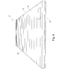
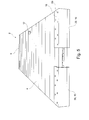
- FIG. 4 and 5 Further simplified perspective views of the tread and work platform 2 are in the FIG. 4 and 5 shown. It shows FIG. 4 the tread and work platform 2 from its lower edge. FIG. 5 shows the tread and work platform 2 in a simplified perspective view of its upper edge.
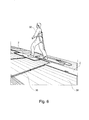
- FIG. 6 shows a simplified perspective view of several tread and work platforms 2, which are mounted on solar panels 28 of a solar system.
- the lock 10 of the stepping and working platforms 2 engages in a gap 30 existing between the individual solar modules 28 of the solar system.
- a user 32 of the stepping and working platforms 2 can move between the individual stepping and working platforms 2 back and forth. By moving the individual tread and work platforms 2, he can easily reach any point of the solar system.
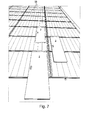
- FIG. 7 shows a further simplified perspective view of attached to the solar modules 28 of a solar system treadmills and work platforms 2.
- the stop surface 22 of the lock 10 of the tread and work platform 2 comes with an upper edge of the solar modules 28 of the solar system shown force and form-fitting to stop, so that the platform and work platforms can not slip even when mounted at an oblique angle solar modules.
- To the Protection of the surface of the solar modules 28 and for additional protection of tread and work platforms is the attached on the bottom 14 of FIG. 2 elastic layer 16th
Landscapes
- Engineering & Computer Science (AREA)
- Architecture (AREA)
- Structural Engineering (AREA)
- Civil Engineering (AREA)
- Sustainable Energy (AREA)
- Thermal Sciences (AREA)
- Chemical & Material Sciences (AREA)
- Combustion & Propulsion (AREA)
- Mechanical Engineering (AREA)
- General Engineering & Computer Science (AREA)
- Physics & Mathematics (AREA)
- Sustainable Development (AREA)
- Life Sciences & Earth Sciences (AREA)
- Rehabilitation Tools (AREA)
- Ladders (AREA)
- Photovoltaic Devices (AREA)
Abstract
Die Erfindung betrifft eine Tritt- und Arbeitsplattform (2) zur Auflage auf zumindest ein in einem schrägem Winkel montiertes Solarmodul (28) einer Solaranlage, umfassend eine Grundplatte (6) und eine daran angebrachte Arretierung (10) zur Sicherung der Tritt- und Arbeitsplattform (2) gegenüber dem Solarmodul (28), wobei sich die Arretierung (10) entlang einer Kante (8) der Grundplatte (6) erstreckt und eine aus einer von der Grundplatte (6) aufgespannten Ebene herausragende Anschlagfläche (22) aufweist, welche dafür vorgesehen ist an einer oben liegenden Kante des in schrägem Winkel montierten Solarmoduls (28) kraft- und/oder formschlüssig zum Anschlag zu kommen.The invention relates to a platform and work platform (2) for resting on at least one solar module (28) of a solar system mounted at an oblique angle, comprising a base plate (6) and a detent (10) attached thereto for securing the footboard and work platform ( 2) with respect to the solar module (28), wherein the lock (10) along an edge (8) of the base plate (6) and a projecting from one of the base plate (6) plane projecting stop surface (22) which provided therefor is at an upper edge of the mounted at an angle solar module (28) non-positively and / or positively come to the stop.
Description
Die Erfindung betrifft eine Tritt- und Arbeitsplattform zur Auflage auf zumindest ein in einem schrägen Winkel montiertes Solarmodul einer Solaranlage.The invention relates to a treadmill and work platform for resting on at least one solar module mounted in an oblique angle of a solar system.
Eine Solaranlage besteht in der Regel aus einer Vielzahl einzelner Solarmodule, welche zu einer großen Fläche, z. B. auf einem Dach eines Gebäudes zusammengesetzt sind. Im Folgenden sollen sowohl Photovoltaikanlagen als auch solarthermische Anlagen allgemein als Solaranlage bezeichnet werden. Die einzelnen Solarmodule weisen an ihrer Oberfläche eine Glasscheibe oder dergleichen auf oder haben zumindest eine lichtdurchlässige Deckschicht. Die Oberfläche solcher Solarmodule ist vergleichsweise empfindlich und sollte aus diesem Grund weder bei der Montage noch bei der Wartung der Solaranlage betreten werden.A solar system usually consists of a large number of individual solar modules, which to a large area, z. B. are assembled on a roof of a building. In the following, both photovoltaic systems and solar thermal systems are generally referred to as a solar system. The individual solar modules have a glass pane or the like on their surface or at least have a light-permeable cover layer. The surface of such solar modules is relatively sensitive and should therefore be entered neither during assembly nor during maintenance of the solar system.
Eine Solaranlage ist jedoch der Witterung ausgesetzt. Im Laufe der Zeit lagern sich z. B. Schwebstoffe oder dergleichen auf der Oberfläche der Solarmodule ab. Da aufgrund dieser Verschmutzung von der nutzbaren Sonnenenergie ein Teil absorbiert oder reflektiert wird, sinkt der Wirkungsgrad der Solaranlage im Laufe der Zeit. Um einer solchen Verringerung des Wirkungsgrades entgegen zu wirken, sollte die Oberfläche der Solarmodule von Zeit zu Zeit gereinigt werden. Eine solche Reinigung ist jedoch mit gewissen technischen Hindernissen behaftet, da sich Solaranlagen in der Regel an schlecht zugänglichen Orten wie z. B. Gebäudedächern befinden. Außerdem sind aufgrund der großen Fläche der Solaranlage zumindest die in einem Innenbereich dieser Fläche liegenden Solarmodule schwer zugänglich. Schließlich muss die Reinigung der Solarmodule mit großer Vorsicht durchgeführt werden, da bereits feine Kratzer in deren Oberfläche eine Verringerung des Wirkungsgrades zur Folge haben.However, a solar system is exposed to the weather. Over time, z. As suspended matter or the like on the surface of the solar modules. As part of this pollution is absorbed or reflected by the usable solar energy, the efficiency of the solar system decreases over time. To counteract such a reduction in efficiency, the surface of the solar modules should be cleaned from time to time. However, such cleaning is fraught with certain technical obstacles, since solar systems usually in poorly accessible places such. B. building roofs are located. Moreover, due to the large area of the Solar system at least the lying in an interior of this area solar modules difficult to access. Finally, the cleaning of the solar modules must be carried out with great care, since even fine scratches in the surface of a reduction in efficiency result.
Zur Reinigung von Solaranlagen, welche auf Gebäudedächern montiert sind, schlägt die
Eine weitere Notwendigkeit, sich Zugang zu einzelnen Solarmodulen einer Solaranlage zu verschaffen, kann beim Austausch von fehlerhaften und defekten Solarmodulen im Rahmen von Wartungsarbeiten entstehen. In einem solchen Fall ist es in der Regel nicht zu vermeiden, dass ein Monteur die Solaranlage betritt. Auch bei größter Vorsicht besteht bei solchen Arbeiten stets die Gefahr, einzelne Solarmodule zu beschädigen.Another need to gain access to individual solar modules of a solar system can arise when replacing faulty and defective solar modules in the context of maintenance. In such a case, it is usually unavoidable that an installer enters the solar system. Even with the utmost care, such work always runs the risk of damaging individual solar modules.
Es ist eine Aufgabe der vorliegenden Erfindung, eine Tritt- und Arbeitsplattform anzugeben, welche einen einfachen und effizienten Zugang zu einer Solaranlagen gestattet.It is an object of the present invention to provide a stepping and working platform which allows easy and efficient access to a solar system.
Gemäß einem Aspekt der Erfindung wird eine Tritt- und Arbeitsplattform zur Auflage auf zumindest ein in einem schrägen Winkel montiertes Solarmodul einer Solaranlage angegeben. Vorzugsweise handelt es sich bei der Solaranlage um eine Photovoltaikanlage. Die Tritt- und Arbeitsplattform kann jedoch ebenfalls für solarthermische Anlagen, welche aus einzelnen flachen Solarmodulen aufgebaut sind, eingesetzt werden. Die gemäß Aspekten der Erfindung ausgestaltete Tritt- und Arbeitsplattform umfasst eine Grundplatte und eine daran angebrachte Arretierung zur Sicherung der Tritt- und Arbeitsplattform gegenüber dem Solarmodul. Die Arretierung erstreckt sich entlang einer Kante der Grundplatte und weist eine Anschlagfläche auf. Diese Anschlagfläche ragt aus einer von der Grundplatte der Tritt- und Arbeitsplattform aufgespannten Ebene heraus. Die Anschlagfläche ist dafür vorgesehen, mit einer obenliegenden Kante des in einem schrägen Winkel montierten Solarmoduls kraft- und/oder formschlüssig zum Anschlag zu kommen.According to one aspect of the invention, a stepping and working platform is specified for resting on at least one solar module of a solar system mounted at an oblique angle. Preferably, the solar system is a photovoltaic system. However, the tread and work platform can also be used for solar thermal systems, which are constructed of individual flat solar modules. The designed according to aspects of the invention treadmill and work platform comprises a base plate and a detent attached thereto for securing the tread and working platform relative to the Solar module. The lock extends along an edge of the base plate and has a stop surface. This stop surface protrudes out of a plane spanned by the base plate of the tread and work platform level. The abutment surface is intended to come with an overhead edge of the mounted in an oblique angle solar module non-positively and / or positively to the stop.
Vorteilhaft kann die Tritt- und Arbeitsplattform gemäß Aspekten der Erfindung auf ein Solarmodul einer Solaranlage aufgesetzt werden, wobei die bei Betreten der Tritt- und Arbeitsplattform auftretenden mechanischen Belastungen großflächig auf das darunterliegende Solarmodul verteilt werden. Das Risiko das Solarmodul zu beschädigen, kann so minimiert werden. Die einzelnen Solarmodule großflächiger Solaranlagen sind unter Freilassung eines Spaltes zwischen den einzelnen Solarmodulen montiert, um eine thermische Ausdehnung der Solarmodule zu ermöglichen. Die Breite dieses Spaltes ist durch die thermische Ausdehnung der Solarmodule bei Erwärmung vorgegeben. Bevorzugt greift die Arretierung von der Oberseite der Solarmodule her in diesen Spalt. Da die Anschlagfläche der Arretierung kraft- und bevorzugt auch formschlüssig an einer dem Spalt benachbarten, oberen Kante des betreffenden Solarmoduls anschlägt, kann ein Abrutschen der Tritt- und Arbeitsplattform wirksam vermieden werden.Advantageously, the treadmill and work platform can be placed according to aspects of the invention on a solar module of a solar system, the mechanical loads occurring on entering the treadmill and work platform are distributed over a large area on the underlying solar module. The risk of damaging the solar module can thus be minimized. The individual solar modules large-scale solar systems are mounted leaving a gap between the individual solar modules to allow thermal expansion of the solar modules. The width of this gap is predetermined by the thermal expansion of the solar modules when heated. Preferably, the lock engages from the top of the solar modules forth in this gap. Since the abutment surface of the locking force and preferably also positively abuts a gap adjacent to the upper edge of the relevant solar module, slippage of the tread and work platform can be effectively avoided.
Diese Anschlagfläche erstreckt sich bevorzugt in Richtung einer Unterseite der Tritt- und Arbeitsplattform aus einer von der Grundplatte aufgespannten Ebene heraus. Weiterhin bevorzugt ist die Anschlagfläche im Wesentlichen senkrecht zu der Grundplatte orientiert. Dies erlaubt eine einfache Handhabung der Tritt- und Arbeitsplattform, welche mit wenigen Handgriffen auf ein Solarmodul aufgesetzt oder von diesem abgehoben werden kann.This stop surface preferably extends in the direction of an underside of the tread and working platform out of a plane spanned by the base plate. Further preferably, the stop surface is oriented substantially perpendicular to the base plate. This allows easy handling of the platform and work platform, which can be placed on a solar module or lifted off it with a few simple steps.
Durch Verwendung mehrerer Tritt- und Arbeitsplattformen, es werden mindestens zwei Tritt- und Arbeitsplattformen benötigt, ist die gesamte Fläche der Solaranlage problemlos zugänglich, indem eine erste Tritt- und Arbeitsplattform als Standfläche dient, während eine zweite Tritt- und Arbeitsplattform von einem vorherigen auf ein nächstes Solarmodul umgesetzt wird. Durch Umsteigen von einer Tritt- und Arbeitsplattform zur nächsten und entsprechendes Umsetzen der Tritt- und Arbeitsplattformen, kann ein Servicetechniker oder einer Reinigungskraft problemlos jeden beliebigen Punkt einer Solaranlage erreichen. Auf den Einsatz aufwendiger und kostspieliger Krananlagen kann vorteilhaft verzichtet werden.By using multiple tread and work platforms, requiring at least two treads and work platforms, the entire surface of the solar system is easily accessible, with a first treadle and work platform serving as a stand space, while a second tread and work platform is used from a previous one next solar module is implemented. By changing from one stepping and working platform to the next and correspondingly implementing the stepping and working platforms, a service technician or a cleaning person can easily reach any point of a solar system. The use of complex and expensive cranes can be advantageously dispensed with.
Gemäß einem vorteilhaften Aspekt der Erfindung weist die Tritt- und Arbeitsplattform auf zumindest einer der Flachseiten der Grundplatte zumindest abschnittsweise, bevorzugt vollflächig, eine elastische Schicht auf. Bevorzugt ist die elastische Schicht auf der von einer Flachseite der Grundplatte gebildeten Unterseite der Tritt- und Arbeitsplattform angebracht. Mit Hilfe der elastischen Schicht kann das Risiko für eine Beschädigung der Oberfläche der Solarmodule weiter minimiert werden. Außerdem verhindert die zwischen der elastischen Schicht und der Oberfläche der Solarmodule vorhandene Haftreibung zusätzlich ein Abrutschen der Tritt- und Arbeitsplattform. Als besonders geeignetes Material für die elastische Schicht konnte Moosgummi gefunden werden. Es hat sich herausgestellt, dass eine auf die Grundplatte aufgeklebte Schicht aus Moosgummi, z. B. ein Moosgummibelag aus Zellkautschuk ZK100, besonders geeignet ist.According to an advantageous aspect of the invention, the treadmill and work platform on at least one of the flat sides of the base plate at least in sections, preferably over the entire surface, an elastic layer. Preferably, the elastic layer is mounted on the bottom of the tread and work platform formed by a flat side of the base plate. With the help of the elastic layer, the risk of damage to the surface of the solar modules can be further minimized. In addition, the existing between the elastic layer and the surface of the solar modules static friction additionally prevents slippage of the tread and work platform. As a particularly suitable material for the elastic layer sponge rubber could be found. It has been found that a glued to the base plate layer of sponge rubber, z. As a foam rubber made of cellular rubber ZK100, is particularly suitable.
Vorteilhaft kann als Arretierung eine sich zumindest abschnittsweise entlang der Kante der Grundplatte erstreckende Profilschiene verwendet werden. Als Material für die Profilschiene ist beispielsweise Aluminium aber auch Kunststoff geeignet. Bevorzugt ist diese Profilschiene in zumindest eine der Flachseiten der Grundplatte eingelassen. Durch Einlassen der Profilschiene in die Grundplatte können hervorstehende Kanten vermieden werden, was das Beschädigungsrisiko für die Solarmodule und das Verletzungsrisiko für den Benutzer minimiert. Bei der Profilschiene handelt es sich bevorzugt um ein zumindest bereichsweise L-förmiges Profil. Dabei ist die Profilschiene in einem senkrecht zu der oberen Kante orientierten Querschnitt zu betrachten. Die Anschlagfläche der Arretierung ist von einem Schenkel eines solchen L-Profils gebildet.Advantageously can be used as a locking at least partially along the edge of the base plate extending rail. As a material for the rail, for example, aluminum but also plastic is suitable. Preferably, this rail is embedded in at least one of the flat sides of the base plate. By leaving the rail in the base plate protruding edges can be avoided, which minimizes the risk of damage to the solar panels and the risk of injury to the user. In the profile rail is preferably an at least partially L-shaped profile. The profile rail is to be considered in a cross-section oriented perpendicular to the upper edge. The stop surface of the lock is formed by a leg of such an L-profile.
Gemäß einem weiteren Ausführungsbeispiel der Erfindung weist die Profilschiene, betrachtet in einem senkrecht zu der oberen Kante orientierten Querschnitt, ein F-Profil auf. Dieses F-Profil weist einen U-förmigen Bereich zur Aufnahme der Grundplatte auf. Die Grundplatte erstreckt sich also in diesen U-förmigen Bereich des F-Profils hinein und ist in diesem Bereich mit der Profilschiene beispielsweise durch Schrauben verbunden. Die F-Profilschiene weist außerdem einen quer zu den Flachseiten der Grundplatte orientierten Schenkel auf, durch welchen die Anschlagfläche gebildet ist. Bevorzugt ist diese Anschlagfläche senkrecht zu den Flachseiten der Grundplatte orientiert, wobei auch in diesem Zusammenhang ein senkrecht zu der oberen Kante orientierter Querschnitt betrachtet wird.According to a further exemplary embodiment of the invention, the profile rail, viewed in a cross-section oriented perpendicular to the upper edge, has an F-profile. This F-profile has a U-shaped area for receiving the base plate. The base plate thus extends into this U-shaped region of the F-profile and is connected in this area with the rail, for example by screws. The F-profile rail also has a transverse to the flat sides of the base plate oriented leg, through which the stop surface is formed. Preferably, this stop surface is oriented perpendicular to the flat sides of the base plate, wherein in this context, a perpendicular to the upper edge oriented cross-section is considered.
Als Material für die Grundplatte ist eine Hartschaumplatte besonders geeignet. Solche Materialien sind leicht und halten hohen Belastungen stand. Bevorzugt wird eine glasfaserverstärkte Polyurethan-Hartschaumplatte verwendet. Dieses Material ist belastbar und gleichzeitig leicht genug, sodass die Tritt- und Arbeitsplattform problemlos in ihrer Handhabung ist. Außerdem ist dieses Material UV-beständig und wasserfest und somit für den Außeneinsatz, insbesondere bei Reinigungsarbeiten der Solarmodule, besonders geeignet.As a material for the base plate a foam board is particularly suitable. Such materials are lightweight and withstand high loads. Preferably, a glass fiber reinforced polyurethane foam board is used. This material is strong and light enough at the same time, so that the platform and work platform is easy to handle. In addition, this material is UV-resistant and waterproof and thus particularly suitable for outdoor use, especially in cleaning of solar modules.
Gemäß einem weiteren Ausführungsbeispiel ist die Tritt- und Arbeitsplattform in einer Längsrichtung größer als in einer quer (bevorzugt im Wesentlichen senkrecht) dazu orientierten Querrichtung. Die Arretierung der Tritt- und Arbeitsplattform erstreckt sich bei diesem Ausführungsbeispiel entlang einer in Querrichtung verlaufenden Kante der Grundplatte. In Aufsicht ist die Grundplatte rechteckig, was bei Verwendung mehrerer Tritt- und Arbeitsplattformen, die während des Arbeitsvorganges versetzt werden, besonders vorteilhaft ist. Aufgrund der länglichen Gestalt der Tritt- und Arbeitsplattform kann eine bisher verwendete weitere Tritt- und Arbeitsplattform in einem unteren Bereich der aktuell verwendeten Tritt- und Arbeitsplattform aufgenommen werden und an deren oberem Ende auf ein weiteres Solarmodul aufsetzen werden. Da die Tritt- und Arbeitsplattform in Längsrichtung groß ist, kann ein großer Arbeitsweg auf einer einzelnen Tritt- und Arbeitsplattform zurückgelegt werden, was den Arbeitsvorgang effizient gestaltet.According to a further embodiment, the treadmill and working platform is larger in a longitudinal direction than in a transverse (preferably substantially perpendicular) oriented transverse direction. The locking of the tread and work platform extends in this embodiment along a transverse edge of the base plate. In plan view, the base plate is rectangular, which is particularly advantageous when using multiple tread and work platforms, which are added during the operation. Due to the elongated shape of the treadmill and work platform, a previously used further treadmill and work platform can be accommodated in a lower area of the currently used treadmill and work platform and placed on top of another solar module. Since the tread and work platform is large in the longitudinal direction, a large work path can be traveled on a single tread and work platform, making work efficient.
Gemäß einem weiteren Aspekt der Erfindung ist eine Flachseite der Grundplatte, welche nicht mit einer elastischen Schicht versehen ist, zumindest abschnittsweise, bevorzugt vollflächig, mit einer rutschfesten Schicht versehen. Eine solche rutschfeste Oberfläche vermindert die Absturzgefährdung auch bei Nässe deutlich. Bevorzugt kann für die rutschfeste Beschichtung eine ZweiKomponenten-Epoxidharzbeschichtung mit eingestreutem, ausgeglühtem, reinem Quarzsand verwendet werden.According to a further aspect of the invention, a flat side of the base plate, which is not provided with an elastic layer, at least in sections, preferably over the entire surface, provided with a non-slip layer. Such a non-slip surface significantly reduces the risk of falling even when wet. Preferably, a two-component epoxy coating with interspersed, annealed, pure quartz sand can be used for the non-slip coating.
Gemäß einem weitem Ausführungsbeispiel ist die Höhe, um die die Anschlagfläche aus der Unterseite der Tritt- und Arbeitsplattform herausragt, kleiner oder gleich einer Dicke der Tritt- und Arbeitsplattform im Bereich der Grundplatte. Vorteilhaft können solche Tritt- und Arbeitsplattformen mit paarweise aufeinanderliegenden Unterseiten gestapelt werden, ohne dass sich ein Quer oder Hochversatz des Stapels einstellt. Die jeweiligen Anschlagflächen überragen im gestapelten Zustand die jeweils benachbarte Platte nicht. Solche Tritt- und Arbeitsplattform können effizient und raumsparend transportiert und aufbewahrt werden.According to a further embodiment, the height by which the stop surface protrudes from the underside of the tread and work platform is less than or equal to a thickness of the tread and work platform in the region of the base plate. Advantageously, such tread and work platforms can be stacked with pairs of superimposed sides, without causing a cross or high offset of the stack. The respective stop surfaces do not protrude beyond the adjacent plate in the stacked state. Such kick and Work platform can be transported and stored efficiently and space-saving.
Im Folgenden wird die Erfindung unter Bezugnahme auf die Zeichnungen weiter erläutert, wobei diese bevorzugte Ausführungsbeispiele der Erfindung zeigen. Es zeigt,
-
FIG. 1 eine vereinfachte perspektivische Ansicht einer Tritt- und Arbeitsplattform von deren Oberseite, gemäß einem Ausführungsbeispiel, -
FIG. 2 eine vereinfachte perspektivische Ansicht dieser Tritt- und Arbeitsplattform von ihrer Unterseite, -
FIG. 3 eine vereinfachte perspektivische Detailansicht einer Tritt- und Arbeitsplattform im Bereich der Arretierung, gemäß einem Ausführungsbeispiel, -
FIG. 4 eine vereinfachte perspektivische Ansicht einer Tritt- und Arbeitsplattform von der Unterkante her, gemäß einem Ausführungsbeispiel, -
FIG. 5 eine weitere vereinfachte perspektivische Ansicht einer Tritt- und Arbeitsplattform von der Oberkante her, gemäß einem Ausführungsbeispiel, und -
FIG. 6 und7 vereinfachte Ansichten mehrerer Tritt- und Arbeitsplattformen im praktischen Einsatz, wobei die Tritt- und Arbeitsplattformen beispielhaft auf eine Solaranlage aufgesetzt sind.
-
FIG. 1 5 is a simplified perspective view of a tread and work platform from the top thereof, according to one embodiment; -
FIG. 2 a simplified perspective view of this tread and work platform from its underside, -
FIG. 3 5 is a simplified perspective detail view of a stepping and working platform in the region of the lock, according to one exemplary embodiment, -
FIG. 4 5 is a simplified perspective view of a stepping and working platform from the lower edge, according to one embodiment, -
FIG. 5 a further simplified perspective view of a tread and work platform from the upper edge ago, according to an embodiment, and -
FIG. 6 and7 simplified views of several tread and work platforms in practical use, the tread and work platforms are exemplary set to a solar system.
Die Tritt- und Arbeitsplattform 2 weist an einer oberen Kante 8, welche sich in einer Querrichtung der Grundplatte 6 erstreckt, eine Arretierung 10 auf. Diese Arretierung 10 besteht aus einem abschnittsweise an der oberen Kante 8 angebrachten Aluminium F-Profil mit einer Schenkellänge von bevorzugt 60 mm. In dem gezeigten Ausführungsbeispiel besteht die Arretierung 10 aus zwei separaten und entlang der oberen Kante 8 beabstandeten F-Profilstücken. Selbstverständlich kann auch ein durchgängiges Profil, welches sich entlang der kompletten oberen Kante 8 erstreckt, eingesetzt werden.The treadmill and
Die Oberseite 4 der Grundplatte 6 ist mit einer rutschfesten Beschichtung versehen, welche bevorzugt aus einer Zwei-Komponenten-Epoxidharzbeschichtung mit eingestreutem, ausgeglühtem, reinem Quarzsand besteht.The
Um die Handhabung der Tritt- und Arbeitsplattform 2 zu erleichtern, weist diese einen in die Grundplatte 6 eingelassenen Griff 12 auf. In der Nähe einer unteren Kante der Grundplatte 6 befindet sich außerdem ein Typenschild 13.In order to facilitate the handling of the tread and
Auf einer der Oberseite 4 gegenüberliegenden Unterseite 14, welche ebenfalls durch eine der Flachseiten der Grundplatte 6 gebildet ist, ist eine elastische Schicht 16 auf die Grundplatte 6 aufgebracht, welche beispielsweise aus einem Moosgummi besteht. Ein bevorzugtes Material für dieses Moosgummi ist Zellkautschuk vom Typ ZK100. Die elastische Schicht 16 ist mit der unteren Flachseite der Grundplatte 6 verklebt. Bevorzugt erstreckt sich die elastische Schicht 16 vollflächig auf der Unterseite 14 der Tritt- und Arbeitsplattform 2. Es ist jedoch ebenfalls möglich, die Unterseite 14 lediglich bereichsweise mit einer elastischen Schicht 16 zu versehen.On one of the top 4 opposite bottom 14, which is also formed by one of the flat sides of the
Die aus einem F-Profil bestehende Arretierung 10 weist neben den in
Die Arretierung 10, d. h. das F-Profil, weist außerdem einen Halteschenkel 20 auf, welcher sich im Wesentlichen senkrecht zu den Flachseiten der Grundplatte 6 erstreckt, sofern wie in
Die kraftschlüssig anliegende Anschlagfläche 22 verhindert gemeinsam mit der zwischen dem Moosgummi und der Oberfläche der Solarmodule auftretenden Haftreibung ein Abrutschen der Tritt- und Arbeitsplattform 2. Auf der Oberseite 4 der Tritt- und Arbeitsplattform 2 ist die Grundplatte 6 mit einer rutschfesten Beschichtung 24 versehen, welche bevorzugt aus einer Zwei-Komponenten-Epoxidharzbeschichtung mit eingestreutem Quarzsand besteht.The frictionally
Wie der
Alternativ zu einem F-Profil kann ein einfaches L-Profil als Arretierung 10 eingesetzt werden. Ein solches L-Profil könnte beispielsweise aus dem oberen Befestigungsschenkel 18 und dem Halteschenkel 20 bestehen.As an alternative to an F-profile, a simple L-profile can be used as a
Weitere vereinfachte perspektivische Ansichten der Tritt- und Arbeitsplattform 2 sind in den
- 22
- Tritt- und ArbeitsplattformStepping and working platform
- 44
- Oberseitetop
- 66
- Grundplattebaseplate
- 88th
- obere Kanteupper edge
- 1010
- Arretierunglock
- 1212
- GriffHandle
- 1414
- Unterseitebottom
- 1616
- elastische Schichtelastic layer
- 1818
- oberer Befestigungsschenkelupper mounting leg
- 1919
- unterer Befestigungsschenkellower mounting leg
- 2020
- Halteschenkelholding leg
- 2222
- Anschlagflächestop surface
- 2424
- rutschfeste Beschichtungnon-slip coating
- 2626
- Schraubenscrew
- 2828
- Solarmodulesolar Panels
- 3030
- Spaltgap
- 3232
- Benutzeruser
- LL
- Längelength
- Breitewidth
- HH
- Höheheight
- DD
- Dickethickness
Claims (14)
Applications Claiming Priority (1)
| Application Number | Priority Date | Filing Date | Title |
|---|---|---|---|
| DE202012001759U DE202012001759U1 (en) | 2012-02-23 | 2012-02-23 | Stepping and working platform |
Publications (3)
| Publication Number | Publication Date |
|---|---|
| EP2631382A2 true EP2631382A2 (en) | 2013-08-28 |
| EP2631382A3 EP2631382A3 (en) | 2014-03-26 |
| EP2631382B1 EP2631382B1 (en) | 2016-06-22 |
Family
ID=46512647
Family Applications (1)
| Application Number | Title | Priority Date | Filing Date |
|---|---|---|---|
| EP13156278.7A Active EP2631382B1 (en) | 2012-02-23 | 2013-02-22 | Step and work platform |
Country Status (2)
| Country | Link |
|---|---|
| EP (1) | EP2631382B1 (en) |
| DE (1) | DE202012001759U1 (en) |
Cited By (3)
| Publication number | Priority date | Publication date | Assignee | Title |
|---|---|---|---|---|
| DE202015102025U1 (en) | 2015-04-23 | 2016-07-27 | Elomat Anlagenbau Wassertechnik GmbH | Stepping and working platform for resting on surfaces of sheet bodies |
| CN108930407A (en) * | 2018-08-17 | 2018-12-04 | 重庆中科建设(集团)有限公司 | The construction method of green roof system |
| CN108999351A (en) * | 2018-09-30 | 2018-12-14 | 九州能源有限公司 | A kind of O&M pedal assembly for color steel roofing photovoltaic system |
Citations (1)
| Publication number | Priority date | Publication date | Assignee | Title |
|---|---|---|---|---|
| DE102009054160A1 (en) | 2009-11-23 | 2011-05-26 | Wocken Industriepartner Gmbh & Co. Kg | Cleaning system for a solar system |
Family Cites Families (5)
| Publication number | Priority date | Publication date | Assignee | Title |
|---|---|---|---|---|
| JP2944560B2 (en) * | 1997-03-25 | 1999-09-06 | 積水化学工業株式会社 | Roof with solar cells and treadboard mounting structure on roof with solar cells |
| US6216819B1 (en) * | 1997-07-16 | 2001-04-17 | Daniel D. Cougar | Kneeling board for roofers |
| US6926241B2 (en) * | 2001-01-22 | 2005-08-09 | Roofmates, Inc. | Roofmates™ roofing accessories |
| US20030037990A1 (en) * | 2001-08-25 | 2003-02-27 | Testa Vincent M. | Roof and shingle protector arrangement |
| US7389856B2 (en) * | 2004-07-26 | 2008-06-24 | Irvin Grady J | Elevated work platform |
-
2012
- 2012-02-23 DE DE202012001759U patent/DE202012001759U1/en not_active Expired - Lifetime
-
2013
- 2013-02-22 EP EP13156278.7A patent/EP2631382B1/en active Active
Patent Citations (1)
| Publication number | Priority date | Publication date | Assignee | Title |
|---|---|---|---|---|
| DE102009054160A1 (en) | 2009-11-23 | 2011-05-26 | Wocken Industriepartner Gmbh & Co. Kg | Cleaning system for a solar system |
Cited By (3)
| Publication number | Priority date | Publication date | Assignee | Title |
|---|---|---|---|---|
| DE202015102025U1 (en) | 2015-04-23 | 2016-07-27 | Elomat Anlagenbau Wassertechnik GmbH | Stepping and working platform for resting on surfaces of sheet bodies |
| CN108930407A (en) * | 2018-08-17 | 2018-12-04 | 重庆中科建设(集团)有限公司 | The construction method of green roof system |
| CN108999351A (en) * | 2018-09-30 | 2018-12-14 | 九州能源有限公司 | A kind of O&M pedal assembly for color steel roofing photovoltaic system |
Also Published As
| Publication number | Publication date |
|---|---|
| EP2631382B1 (en) | 2016-06-22 |
| DE202012001759U1 (en) | 2012-05-02 |
| EP2631382A3 (en) | 2014-03-26 |
Similar Documents
| Publication | Publication Date | Title |
|---|---|---|
| DE102013207827B4 (en) | Device for fixing solar modules and roof | |
| DE102009024615A1 (en) | Mounting system for PV modules | |
| EP2423409B1 (en) | Protective wall | |
| DE102014011022A1 (en) | mounting bracket | |
| EP3225739B1 (en) | Wall element | |
| EP1496550A2 (en) | Mounting system for framed photovoltaic modules | |
| EP2631382B1 (en) | Step and work platform | |
| DE29815134U1 (en) | Device for installing solar panels | |
| DE202009010381U1 (en) | combination plate | |
| DE202013010500U1 (en) | Device for storing and transporting glass panes | |
| DE102022115264A1 (en) | Device for loading and positioning prefabricated roof elements | |
| EP2527763A2 (en) | Cladding system for cladding the external surface of a building | |
| DE202014000276U1 (en) | balcony system | |
| DE102012104415A1 (en) | Flooring | |
| DE202010008421U1 (en) | Support system for solar modules | |
| EP2460947B1 (en) | Glazing | |
| DE202010005391U1 (en) | Mounting kit for solar modules on a flat surface | |
| WO1998049411A1 (en) | Fixing device for roof fittings | |
| DE202008013886U1 (en) | Canopy and cantilever for this | |
| DE102020118104B4 (en) | Protection device for building scaffolding | |
| DE202013009557U1 (en) | Tonnendach with mounting arrangement | |
| DE102013014196A1 (en) | Elevator shaft lining for facade lifts | |
| EP2770136B1 (en) | Fastening bracket for ceiling edge formwork | |
| EP1589158A2 (en) | Device for fastening façade elements | |
| EP1094174A1 (en) | Protective weathercovering for scaffolds used for facades |
Legal Events
| Date | Code | Title | Description |
|---|---|---|---|
| PUAI | Public reference made under article 153(3) epc to a published international application that has entered the european phase |
Free format text: ORIGINAL CODE: 0009012 |
|
| AK | Designated contracting states |
Kind code of ref document: A2 Designated state(s): AL AT BE BG CH CY CZ DE DK EE ES FI FR GB GR HR HU IE IS IT LI LT LU LV MC MK MT NL NO PL PT RO RS SE SI SK SM TR |
|
| AX | Request for extension of the european patent |
Extension state: BA ME |
|
| PUAL | Search report despatched |
Free format text: ORIGINAL CODE: 0009013 |
|
| AK | Designated contracting states |
Kind code of ref document: A3 Designated state(s): AL AT BE BG CH CY CZ DE DK EE ES FI FR GB GR HR HU IE IS IT LI LT LU LV MC MK MT NL NO PL PT RO RS SE SI SK SM TR |
|
| AX | Request for extension of the european patent |
Extension state: BA ME |
|
| RIC1 | Information provided on ipc code assigned before grant |
Ipc: E04G 21/30 20060101ALI20140217BHEP Ipc: E04D 15/00 20060101ALI20140217BHEP Ipc: E04D 13/12 20060101AFI20140217BHEP Ipc: F24J 2/46 20060101ALI20140217BHEP |
|
| 17P | Request for examination filed |
Effective date: 20140924 |
|
| RBV | Designated contracting states (corrected) |
Designated state(s): AL AT BE BG CH CY CZ DE DK EE ES FI FR GB GR HR HU IE IS IT LI LT LU LV MC MK MT NL NO PL PT RO RS SE SI SK SM TR |
|
| 17Q | First examination report despatched |
Effective date: 20150120 |
|
| GRAP | Despatch of communication of intention to grant a patent |
Free format text: ORIGINAL CODE: EPIDOSNIGR1 |
|
| INTG | Intention to grant announced |
Effective date: 20160104 |
|
| GRAS | Grant fee paid |
Free format text: ORIGINAL CODE: EPIDOSNIGR3 |
|
| GRAA | (expected) grant |
Free format text: ORIGINAL CODE: 0009210 |
|
| AK | Designated contracting states |
Kind code of ref document: B1 Designated state(s): AL AT BE BG CH CY CZ DE DK EE ES FI FR GB GR HR HU IE IS IT LI LT LU LV MC MK MT NL NO PL PT RO RS SE SI SK SM TR |
|
| REG | Reference to a national code |
Ref country code: GB Ref legal event code: FG4D Free format text: NOT ENGLISH |
|
| REG | Reference to a national code |
Ref country code: CH Ref legal event code: EP |
|
| REG | Reference to a national code |
Ref country code: IE Ref legal event code: FG4D Free format text: LANGUAGE OF EP DOCUMENT: GERMAN |
|
| REG | Reference to a national code |
Ref country code: AT Ref legal event code: REF Ref document number: 807761 Country of ref document: AT Kind code of ref document: T Effective date: 20160715 |
|
| REG | Reference to a national code |
Ref country code: DE Ref legal event code: R096 Ref document number: 502013003439 Country of ref document: DE |
|
| REG | Reference to a national code |
Ref country code: CH Ref legal event code: NV Representative=s name: BUGNION S.A., CH |
|
| REG | Reference to a national code |
Ref country code: NL Ref legal event code: FP |
|
| REG | Reference to a national code |
Ref country code: LT Ref legal event code: MG4D |
|
| PG25 | Lapsed in a contracting state [announced via postgrant information from national office to epo] |
Ref country code: LT Free format text: LAPSE BECAUSE OF FAILURE TO SUBMIT A TRANSLATION OF THE DESCRIPTION OR TO PAY THE FEE WITHIN THE PRESCRIBED TIME-LIMIT Effective date: 20160622 Ref country code: FI Free format text: LAPSE BECAUSE OF FAILURE TO SUBMIT A TRANSLATION OF THE DESCRIPTION OR TO PAY THE FEE WITHIN THE PRESCRIBED TIME-LIMIT Effective date: 20160622 Ref country code: NO Free format text: LAPSE BECAUSE OF FAILURE TO SUBMIT A TRANSLATION OF THE DESCRIPTION OR TO PAY THE FEE WITHIN THE PRESCRIBED TIME-LIMIT Effective date: 20160922 |
|
| PG25 | Lapsed in a contracting state [announced via postgrant information from national office to epo] |
Ref country code: GR Free format text: LAPSE BECAUSE OF FAILURE TO SUBMIT A TRANSLATION OF THE DESCRIPTION OR TO PAY THE FEE WITHIN THE PRESCRIBED TIME-LIMIT Effective date: 20160923 Ref country code: HR Free format text: LAPSE BECAUSE OF FAILURE TO SUBMIT A TRANSLATION OF THE DESCRIPTION OR TO PAY THE FEE WITHIN THE PRESCRIBED TIME-LIMIT Effective date: 20160622 Ref country code: SE Free format text: LAPSE BECAUSE OF FAILURE TO SUBMIT A TRANSLATION OF THE DESCRIPTION OR TO PAY THE FEE WITHIN THE PRESCRIBED TIME-LIMIT Effective date: 20160622 Ref country code: RS Free format text: LAPSE BECAUSE OF FAILURE TO SUBMIT A TRANSLATION OF THE DESCRIPTION OR TO PAY THE FEE WITHIN THE PRESCRIBED TIME-LIMIT Effective date: 20160622 Ref country code: LV Free format text: LAPSE BECAUSE OF FAILURE TO SUBMIT A TRANSLATION OF THE DESCRIPTION OR TO PAY THE FEE WITHIN THE PRESCRIBED TIME-LIMIT Effective date: 20160622 |
|
| PG25 | Lapsed in a contracting state [announced via postgrant information from national office to epo] |
Ref country code: IS Free format text: LAPSE BECAUSE OF FAILURE TO SUBMIT A TRANSLATION OF THE DESCRIPTION OR TO PAY THE FEE WITHIN THE PRESCRIBED TIME-LIMIT Effective date: 20161022 Ref country code: IT Free format text: LAPSE BECAUSE OF FAILURE TO SUBMIT A TRANSLATION OF THE DESCRIPTION OR TO PAY THE FEE WITHIN THE PRESCRIBED TIME-LIMIT Effective date: 20160622 Ref country code: SK Free format text: LAPSE BECAUSE OF FAILURE TO SUBMIT A TRANSLATION OF THE DESCRIPTION OR TO PAY THE FEE WITHIN THE PRESCRIBED TIME-LIMIT Effective date: 20160622 Ref country code: CZ Free format text: LAPSE BECAUSE OF FAILURE TO SUBMIT A TRANSLATION OF THE DESCRIPTION OR TO PAY THE FEE WITHIN THE PRESCRIBED TIME-LIMIT Effective date: 20160622 Ref country code: RO Free format text: LAPSE BECAUSE OF FAILURE TO SUBMIT A TRANSLATION OF THE DESCRIPTION OR TO PAY THE FEE WITHIN THE PRESCRIBED TIME-LIMIT Effective date: 20160622 Ref country code: EE Free format text: LAPSE BECAUSE OF FAILURE TO SUBMIT A TRANSLATION OF THE DESCRIPTION OR TO PAY THE FEE WITHIN THE PRESCRIBED TIME-LIMIT Effective date: 20160622 |
|
| REG | Reference to a national code |
Ref country code: FR Ref legal event code: PLFP Year of fee payment: 5 |
|
| PG25 | Lapsed in a contracting state [announced via postgrant information from national office to epo] |
Ref country code: PL Free format text: LAPSE BECAUSE OF FAILURE TO SUBMIT A TRANSLATION OF THE DESCRIPTION OR TO PAY THE FEE WITHIN THE PRESCRIBED TIME-LIMIT Effective date: 20160622 Ref country code: ES Free format text: LAPSE BECAUSE OF FAILURE TO SUBMIT A TRANSLATION OF THE DESCRIPTION OR TO PAY THE FEE WITHIN THE PRESCRIBED TIME-LIMIT Effective date: 20160622 Ref country code: PT Free format text: LAPSE BECAUSE OF FAILURE TO SUBMIT A TRANSLATION OF THE DESCRIPTION OR TO PAY THE FEE WITHIN THE PRESCRIBED TIME-LIMIT Effective date: 20161024 Ref country code: SM Free format text: LAPSE BECAUSE OF FAILURE TO SUBMIT A TRANSLATION OF THE DESCRIPTION OR TO PAY THE FEE WITHIN THE PRESCRIBED TIME-LIMIT Effective date: 20160622 |
|
| REG | Reference to a national code |
Ref country code: DE Ref legal event code: R097 Ref document number: 502013003439 Country of ref document: DE |
|
| PLBE | No opposition filed within time limit |
Free format text: ORIGINAL CODE: 0009261 |
|
| STAA | Information on the status of an ep patent application or granted ep patent |
Free format text: STATUS: NO OPPOSITION FILED WITHIN TIME LIMIT |
|
| 26N | No opposition filed |
Effective date: 20170323 |
|
| PG25 | Lapsed in a contracting state [announced via postgrant information from national office to epo] |
Ref country code: DK Free format text: LAPSE BECAUSE OF FAILURE TO SUBMIT A TRANSLATION OF THE DESCRIPTION OR TO PAY THE FEE WITHIN THE PRESCRIBED TIME-LIMIT Effective date: 20160622 |
|
| PG25 | Lapsed in a contracting state [announced via postgrant information from national office to epo] |
Ref country code: SI Free format text: LAPSE BECAUSE OF FAILURE TO SUBMIT A TRANSLATION OF THE DESCRIPTION OR TO PAY THE FEE WITHIN THE PRESCRIBED TIME-LIMIT Effective date: 20160622 |
|
| PG25 | Lapsed in a contracting state [announced via postgrant information from national office to epo] |
Ref country code: MC Free format text: LAPSE BECAUSE OF FAILURE TO SUBMIT A TRANSLATION OF THE DESCRIPTION OR TO PAY THE FEE WITHIN THE PRESCRIBED TIME-LIMIT Effective date: 20160622 |
|
| REG | Reference to a national code |
Ref country code: IE Ref legal event code: MM4A |
|
| REG | Reference to a national code |
Ref country code: FR Ref legal event code: PLFP Year of fee payment: 6 |
|
| PG25 | Lapsed in a contracting state [announced via postgrant information from national office to epo] |
Ref country code: IE Free format text: LAPSE BECAUSE OF NON-PAYMENT OF DUE FEES Effective date: 20170222 |
|
| PG25 | Lapsed in a contracting state [announced via postgrant information from national office to epo] |
Ref country code: MT Free format text: LAPSE BECAUSE OF FAILURE TO SUBMIT A TRANSLATION OF THE DESCRIPTION OR TO PAY THE FEE WITHIN THE PRESCRIBED TIME-LIMIT Effective date: 20160622 |
|
| PG25 | Lapsed in a contracting state [announced via postgrant information from national office to epo] |
Ref country code: AL Free format text: LAPSE BECAUSE OF FAILURE TO SUBMIT A TRANSLATION OF THE DESCRIPTION OR TO PAY THE FEE WITHIN THE PRESCRIBED TIME-LIMIT Effective date: 20160622 |
|
| PG25 | Lapsed in a contracting state [announced via postgrant information from national office to epo] |
Ref country code: HU Free format text: LAPSE BECAUSE OF FAILURE TO SUBMIT A TRANSLATION OF THE DESCRIPTION OR TO PAY THE FEE WITHIN THE PRESCRIBED TIME-LIMIT; INVALID AB INITIO Effective date: 20130222 |
|
| PG25 | Lapsed in a contracting state [announced via postgrant information from national office to epo] |
Ref country code: BG Free format text: LAPSE BECAUSE OF FAILURE TO SUBMIT A TRANSLATION OF THE DESCRIPTION OR TO PAY THE FEE WITHIN THE PRESCRIBED TIME-LIMIT Effective date: 20160622 |
|
| PG25 | Lapsed in a contracting state [announced via postgrant information from national office to epo] |
Ref country code: CY Free format text: LAPSE BECAUSE OF NON-PAYMENT OF DUE FEES Effective date: 20160622 |
|
| PG25 | Lapsed in a contracting state [announced via postgrant information from national office to epo] |
Ref country code: MK Free format text: LAPSE BECAUSE OF FAILURE TO SUBMIT A TRANSLATION OF THE DESCRIPTION OR TO PAY THE FEE WITHIN THE PRESCRIBED TIME-LIMIT Effective date: 20160622 |
|
| PG25 | Lapsed in a contracting state [announced via postgrant information from national office to epo] |
Ref country code: TR Free format text: LAPSE BECAUSE OF FAILURE TO SUBMIT A TRANSLATION OF THE DESCRIPTION OR TO PAY THE FEE WITHIN THE PRESCRIBED TIME-LIMIT Effective date: 20160622 |
|
| P01 | Opt-out of the competence of the unified patent court (upc) registered |
Effective date: 20230516 |
|
| PGFP | Annual fee paid to national office [announced via postgrant information from national office to epo] |
Ref country code: LU Payment date: 20240220 Year of fee payment: 12 |
|
| PGFP | Annual fee paid to national office [announced via postgrant information from national office to epo] |
Ref country code: NL Payment date: 20240219 Year of fee payment: 12 |
|
| PGFP | Annual fee paid to national office [announced via postgrant information from national office to epo] |
Ref country code: AT Payment date: 20240220 Year of fee payment: 12 |
|
| PGFP | Annual fee paid to national office [announced via postgrant information from national office to epo] |
Ref country code: GB Payment date: 20240219 Year of fee payment: 12 Ref country code: CH Payment date: 20240301 Year of fee payment: 12 |
|
| PGFP | Annual fee paid to national office [announced via postgrant information from national office to epo] |
Ref country code: FR Payment date: 20240221 Year of fee payment: 12 Ref country code: BE Payment date: 20240219 Year of fee payment: 12 |
|
| REG | Reference to a national code |
Ref country code: CH Ref legal event code: PL |
|
| REG | Reference to a national code |
Ref country code: NL Ref legal event code: MM Effective date: 20250301 |
|
| PG25 | Lapsed in a contracting state [announced via postgrant information from national office to epo] |
Ref country code: LU Free format text: LAPSE BECAUSE OF NON-PAYMENT OF DUE FEES Effective date: 20250222 |
|
| REG | Reference to a national code |
Ref country code: AT Ref legal event code: MM01 Ref document number: 807761 Country of ref document: AT Kind code of ref document: T Effective date: 20250222 |
|
| PG25 | Lapsed in a contracting state [announced via postgrant information from national office to epo] |
Ref country code: AT Free format text: LAPSE BECAUSE OF NON-PAYMENT OF DUE FEES Effective date: 20250222 |
|
| PG25 | Lapsed in a contracting state [announced via postgrant information from national office to epo] |
Ref country code: CH Free format text: LAPSE BECAUSE OF NON-PAYMENT OF DUE FEES Effective date: 20250228 |
|
| GBPC | Gb: european patent ceased through non-payment of renewal fee |
Effective date: 20250222 |
|
| PG25 | Lapsed in a contracting state [announced via postgrant information from national office to epo] |
Ref country code: NL Free format text: LAPSE BECAUSE OF NON-PAYMENT OF DUE FEES Effective date: 20250301 |
|
| REG | Reference to a national code |
Ref country code: BE Ref legal event code: MM Effective date: 20250228 |
|
| PG25 | Lapsed in a contracting state [announced via postgrant information from national office to epo] |
Ref country code: GB Free format text: LAPSE BECAUSE OF NON-PAYMENT OF DUE FEES Effective date: 20250222 |
|
| PG25 | Lapsed in a contracting state [announced via postgrant information from national office to epo] |
Ref country code: FR Free format text: LAPSE BECAUSE OF NON-PAYMENT OF DUE FEES Effective date: 20250228 |
|
| PG25 | Lapsed in a contracting state [announced via postgrant information from national office to epo] |
Ref country code: BE Free format text: LAPSE BECAUSE OF NON-PAYMENT OF DUE FEES Effective date: 20250228 |
|
| PGFP | Annual fee paid to national office [announced via postgrant information from national office to epo] |
Ref country code: DE Payment date: 20260121 Year of fee payment: 14 |